1
AMWD STANDARD
WORK PROCEDURE
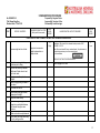
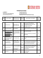
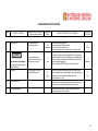
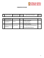
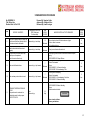
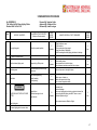
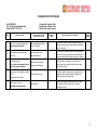
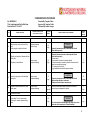
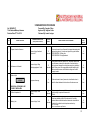
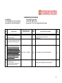
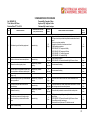
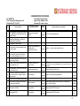
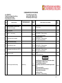
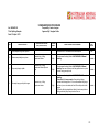
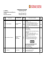
Index of Standard
Work Procedures Surface
Surface Health, Safety 8. Environment. 1.01 —- 1.24
Reviewed
SURHSE1.01
SURHSE1.02
SURHSE1.03
SURHSE1.04
SURHSE1.05
SURHSE1.07
SURHSE1.08
SURHSE1.10
SURHSE1.13
SURHSE1.14
SURHSE1.15
SURHSE1.16
SURHSE1.17
SURHSE1.18
SURHSE1.19
SURHSE1.21
SURHSE1.22
SURHSE1.23
SURHSE1.24
SURHSE1.06
SURHSE1.09
SURHSE1.11
SURHSE1.24
Personal Protective Equipment
Manual Handling
House Keeping Work Area
House Keeping Tools
Isolation Lock Out All Vehicles and
Plant
Isolation Compression
Shift Change Surface and Cross
Shift Handover
Vehicle Daily Inspection and Pre
Start
Operate Salamander
Chemical Handling
Travelling between sites in remote
Areas
Emergency Procedure Gas
Intersection Diamond and Mud
Rotary.
Unpack New Rods
Emergency Procedure Drill Rig Fire
Emergency Procedure Gas
Blowout
Use of Gas detector LEL
Rescue from Derrick UDR3000
Rise Set Up Bollard & H/Rails on
Derrick UDR3000
Use of Rescue Master UDR3000
Isolation Drill Rigs
Cross Shift Hand Over
Truck Daily Check
Pre Start Check List Surface
PA SURHSE 1.01
05/2006
PA SURHSE 1.02
05/2006
PA SURHSE 1.03
05/2006
PA SURHSE 1.04
05/2006
PA SURHSE 1.05
05/2006
PA SURHSE 1.07
05/2006
PA SURHSE 1.08
05/2006
PA SURHSE 1.10
05/2006
PA SURHSE 1.13
05/2006
PA SURHSE 1.14
05/2006
PA SURHSE 1.15
05/2006
PA SURHSE 1.16
05/2006
PA SURHSE 1.17
08/2006
PA SURHSE 1.18
05/2006
PA SURHSE 1.19
05/2006
PA SURHSE 1.21
06/2006
PA SURHSE 1.22
Archived
Archived
Archived
Delete- in 1.05
Delete- in 1.06
Delete- in 1.10
Delete- in 1.10
1
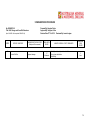
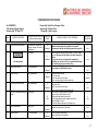
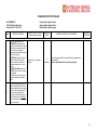
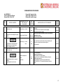
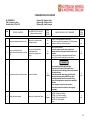
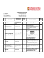
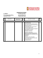
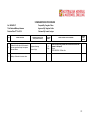
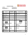
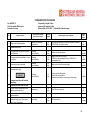
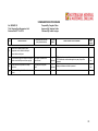
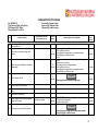
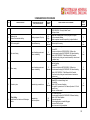
Index of Standard
Work Procedures Surface
Surface General 2.01 —— 2.37
SURGEN2.01
SURGEN2.02
SURGEN2.03
SURGEN2.04
SURGEN2.05
SURGENZOB
SURGEN2.07
SURGEN2.08
SURGEN2.09
SURGEN2.10
SURGEN2.11
SURGEN2.12
SURGEN2.13
SURGEN2.14
SURGEN2.15
SURGEN2.16
SURGEN2·17
SURGEN2.18
SURGEN2.19
SURGEN2.20
SURGEN2.21
SURGEN2.22
SURGEN2.23
SURGEN2.24
SURGEN2.25
SURGEN2.26
SURGEN2.27
SURGEN2.28
SURGEN2.29
SURGEN2.30
SURGEN2.31
SURGEN2.32
SURGEN2.33
SURGEN2.34
SURGEN2.35
Acquire Equipment for Mobilization
Refuel Diesel Engines
Hiab Operation
Secure Load Site Move
Site Move Surface
Set Up Surface Rig
Raising Mast Wedge instructions
Raising Mast UDR 1000/UDR1200
Raising Mast 45 to 66 Degrees
Raising Mast 66 to 90 Degrees
Lower Mast 66 to 90 Degrees
Lower Mast 45 to 66 Degrees
Main Winch Operation
UDR650/1000/1200
Wire Line Winch Operation
Ascending & Descending UDR Mast
Climbing UDR Masts
Mixing Mud
Using a Marsh Funnel
Stilson Use
Using Break Out Stilson
Repair Stilsons
Setting Up/Pull Down Lighting Plant
Set up Lay down Area
Install BOP
Test BOP
Calculate and Record Hole Depth
Loading — Unloading Rod Spinner
Tramming Track Mounted Rig
UDR3OOO - Setup of Surface Rig
Drill Sump Usage
Mud Pump Operation
Grinders — Bench and Hand Held
Load / Unload Rods manually from
Vehicle
Load / Unload and Set up Rod Sloop
UDR3OOO - Ascending & Descending
PA SURGEN 2.01
05/2006
PA SURGEN 2.02
05/2006
PA SURGEN 2.03
01/2006
PA SURGEN 2.04
05/2006
PA SURGEN 2.05
05/2006
PA SURGEN 2.06
05/2006
PA SURGEN 2.07
Archived
PA SURGEN 2.08
PA SURGEN 2.09
Archived
Archived
PA SURGEN 2.10
Archived
PA SURGEN 2.11
Archived
PA SURGEN 2.12
Archived
PA SURGEN 2.13
05/2006
PA SURGEN 2.14
06/2006
PA SURGEN 2.15
Archived
PA SURGEN 2.16
Archived
PA SURGEN 2.17
05/2006
PA SURGEN 2.18
05/2006
PA SURGEN 2.19
05/2006
PA SURGEN 2.20
05/2006
PA SURGEN 2.21
05/2006
PA SURGEN 2.22
05/2006
PA SURGEN 2.23
05/2006
PA SURGEN 2.24
03/2006
PA SURGEN 2.25
03/2006
PA SURGEN 2.26
05/2006
PA SURGEN 2.27
05/2006
PA SURGEN 2.28
09/2006
PA SURGEN 2.29
Archived
PA SURGEN 2.30
03/2006
PA SURGEN 2.31
06/2006
PA SURGEN 2.32
06/2006
PA SURGEN 2.33
06/2006
PA SURGEN 2.34
06/2006
PA SURGEN 2.35
Archived
2
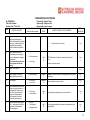
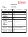
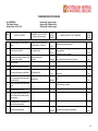
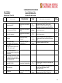
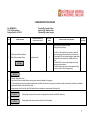
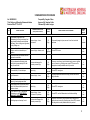
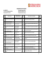
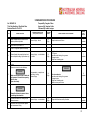
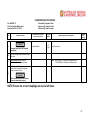
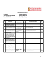
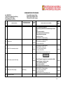
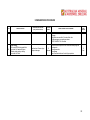
Index of Standard
Work Procedures Surface
SURGEN2.36
SURGEN2.37
Ladder to Top Platform
Setting Up & Operating Salamander
Heater
UDR3000 - Raising Mast
PA SURGEN 2.36
07/2006
PA-SURGEN2.37
O7/2006
PA SURAIR3.01
05/2006
PA SURAIR3.02
05/2006
PA SURAIR3.03
03/2006
PA SURAlR3 0
05/2006
PA SURAIR3.05
05/2006
PA SURAIR3.07
05/2006
PA SURAIR3.08
05/2006
PA SURAIR3.09
05/2006
PA SURAIR3.10
05/2006
PA SURAIR3.11
05/2006
PA SURAIR3.13
05/2006
PA SURAIR3.14
05/2006
PA SURAIR3.15
05/2006
PA SURAIR3.16
03/2006
PA SURAIR3.17
05/2006
PA SURAIR3.18
05/2006
Surface Air (RC Percussion). 3.01 — 3.24
SURAlR3.01
SURAIR3.02
SURAlR3.03
SURAIR3.04
SURAlR3.05
SURAlR3.07
SURAlR3.08
SURAlR3.09
SURAIR3.10
SURAlR3.11
SURAlR3.13
SURAIR3.14
SURAlR3.15
SURAIR3.16
SURAlR3.17
SURAlR3.18
SURAlR3.19
SURAlR3.20
SURAlR3.21
SURAlR3.22
SURAlR3.23
SURAIR3.24
SURAIR3.06
SURAIR3.12
Compressor Safety
Compressor Start Up
Sandvik Rod Handler
Rod Pull with Rod handler
Running & Pulling RC Rods
Break Out/Makeup Hammer
Remove & Replacing RC Bits
Assembly of RC 55 Hammer
RC Collar and Install Stuffing Box
Setting Rotation —~ Percussion Drilling
Safe Handling of Blow Down Sub
Safe Handling of Blow Back Sub
Removing & Assemble High
Pressure Hoses, (Cyclone, Pumps,
Booster)
Unblock RC Hose
Preventative Maintenance procedure
for Hoses
RC Hose Fittings
Cleaning Dust Suppression Unit
Drill Clean Dust Collector
Maintenance
Running Tubex Casing using SOS
Hammer & RC Rods
Pulling Tubex Casing
Injecting Mist or Foam
Back Hammer
Pulling RC Rods
RC Drilling
03/2006
03/2006
05/2006
05/2006
PA SURAIR3.23
PA SURAIR2.33
05/2006
Deleted- in 3.05
Deleted- in 3.11
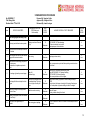
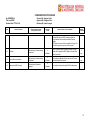
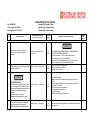
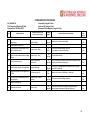
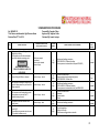
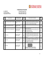
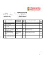
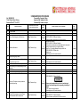
Surface Mud Rotary. 4.01 — 4.04
3
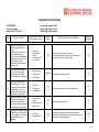
Index of Standard
Work Procedures Surface
SURMUD4.01
SURMUD4.02
SURMUD4.03
SURMUD4.04
Rotary Mud Collar &. Install Blooie
Line and Diverter
Grout Aquifer and Plug Hole
Pump Van Ruth and Grout Hole
Annulus Grout Hole
PA SURMUD4.01
05/2006
PA SURMUD4.02
05/2006
PA SURMUD4.03
05/2006
PA SURMUD4.04
05/2006
Drilling Surface Diamond 5.01 —- 5.29
SURDIA5.01
SURDlA5.02
SURDlA5.03
SURDlA5.04
SURDlA5.05
SURDlA5.06
SURDlA5.07
SURDlA5.08
SURDlA5.09
SURDlA5.10
SURDIA5.11
SURDlA5.12
SURDlA5.13
SURDlA5.15
SURDlA5.16
SURDlA5.17
SURDlA5.18
SURDIA5·19
SURDlA5.20
SURDlA5.21
SURDlA5.22
SURDlA5.23
Running/Pulling and Seating Casing
PA SURMUD5.01
06/2006
at Start of Hole Haul Plug
Lower Core Barrel 82 Rods
PA SURMUD5.02
05/2006
Setting Hold Back, Pull Down &
PA SURMUD5.03
08/2006
Micro Feed
Setting Rotation — Diamond Drilling
PA SURMUD5.04
08/2006
Diamond Drilling
PA SURMUD5.05
05/2006
Use of Power Stilson
PA SURMUD5.06
08/2006
Core Tube Recovery
PA SURMUD5.07
05/2006
Empty Core Tubes & Wash Core
PA SURMUD5.08
05/2006
Pumping Out Splits & Removing
PA SURMUD5.09
05/2006
Core from Q3 Inner Tube
Correct Core Presentation
PA SURMUD5.10
05/2006
Pulling St Running Rods Hoist Plug
PA SURMUD5.11
06/2006
Pull & Run Rods Using Rod Stacking
PA SURMUD5.12
08/2006
Bar- Rods in Mast
Rod Vibrations Dry Hole & Bent
PA SURMUD5.13
05/2006
Rods
Rod Vibration Rig off Line
PA SURMUD5.15
05/2006
Lost Circulation
PA SURMUD5.16
05/2006
Add Remove Rods with
PA SURMUD5.17
05/2006
Clamshell. Run/Pull Rods & Casing
with Clamshell.
Differential Stick — Methods 1, 2 & 3
PA SURMUD5.18
05/2006
Stuck Rods
PA SURMUD5.19
05/2006
Stripping impregnated Bits
PA SURMUD5.20
05/2006
Assemble Q Series Outer Tube
PA SURMUD5.21
05/2006
Assemble Q Series Inner Tube
PA SURMUD5.22
05/2006
Assemble Q3 Series inner
PA SURMUD5.23
05/2006
Tube/Adjust length
4
Index of Standard
Work Procedures Surface
SURDlA5.25
SLlRDlA5.26
SURDlA5.27
SURDlA5.28
SURDlA5.29
SURDlA5.14
SURDlA5.24
Assembly of Universal Water Swivel
Changing Over Shot Lifting Dogs
Mount & Dismount Work Platform
Change O Series Back End Parts
Core Orientation with Pencil Tip
Spear Wireline
Rod Vibration Bent Rods
Adjust Length Q Series Inner Tube
PA SURMUD5.25
05/2006
PA SURMUD5.26
05/2006
PA SURMUD5.27
05/2006
PA SURMUD5.28
05/2006
PA SURMUD5.29
05/2006
Delete- in 5.13
Delete- in 5.23
Maintenance General. 6.00 — 6.19
MAlNGEN6.00
MAlNGEN6.01
MAINGEN6.02
MAlNGEN6.03
MAlNGEN6.04
MAlNGEN6.05
MAINGEN6.06
MAlNGEN6.07
MAlNGEN6.08
MAlNGEN6.09
MAlNGEN6.10
MAINGEN6.11
MAINGEN6.12
MAlNGEN6.13
MAlNGEN6.14
MAlNGEN6.15
MAINGEN6.16
MAlNGEN6.17
MAINGEN6.18
MAlNGEN6.l9
Change 8 Repair Hydraulic Hose
Change Hydraulic Pressure Gauge
Change Valves 8 Buckets Bean
Pump
Replace Plunger Packing Bean
Pump
Overhaul Relief Valve
Fitting Cable Clamps
Replace Alternator on Diesel
Engine
Replace Starter Motor on Diesel
Engine
Replace "V” Belt on Diesel Engine
Replace Water Hose on Diesel
Engine
Charging 12 Volt Battery
Jump Start 12 Volt System
Jump Start 24 Volt System
Vibration Noise from Head Transmission
Light Vehicle Daily Inspection
Truck Daily Check
Remove Flat Tires — Light Vehicles
Removing Flat Tires - Trucks
Snowmobile — Pre — Operational
Check
Pre —- Operational Check — Skidder
PA MAINGEN6.00
05/2006
PA MAINGEN6.01
05/2006
PA MAINGEN6.02
05/2006
PA MAINGEN6.03
03/2006
PA MAINGEN6.04
05/2006
PA MAINGEN6.05
05/2006
PA MAINGEN6.06
05/2006
PA MAINGEN6.07
05/2006
PA MAINGEN6.08
05/2006
PA MAINGEN6.09
05/2006
PA MAINGEN6.10
05/2006
PA MAINGEN6.11
05/2006
PA MAINGEN6.12
05/2006
PA MAINGEN6.13
05/2006
PA MAINGEN6.14
PA MAINGEN6.15
03/2006
PA MAINGEN6.16
05/2006
PA MAINGEN6.17
05/2006
PA MAINGEN6.18
05/2006
PA MAINGEN6.19
05/2006
Directional 8.01 — 8.10
5
Index of Standard
Work Procedures Surface
DlR8.01
DlR8.02
DlR8.03
DlR8.04
DlR8.05
DlR8.09
DlR8.10
Navi Drill Pre Check
Down Hole Motor
Down Hole Motor Navi
Run Survey Camera and Orientate
Tool
Steer Tool Survey
Pilot Hole Break through Drilling
Pilot Hole Reaming
PA-DIR8.01
05/2006
PA-DIR8.02
05/2006
PA-DIR8.03
03/2006
PA-DIR8.04
05/2006
PA-DIR8.05
05/2006
PA-DIR8.09
05/2006
PA-DIR8.10
05/2006
Set up Head Rod
PA-2OODGEN10.01
Set up to Run Survey
PA-2OODGEN10.02
Change chuck jaws and guide
PA-2OODGEN10.03
Bushes
Setting Up Guard Rails and No- PA-2OODGEN10.04
Go Zones UDR2OOD
Placing Kelly Rod & Drilling on
PA-2OODGEN10.05
UDR2OOD
Removing Kelly Rod
PA-2OODGEN10.06
Pulling and Running Rods and PA-2OODGEN10.07
Casing 200D
Raising Mast and Connecting
PA-2OODGEN10.08
Stay Rods
Adding 3m Rod
PA-2OODGEN10.09
Changing Head Gear & Greasing PA-2OODGEN10.10
Sheave Wheels
Pulling Rods through Head
PA-2OODGEN10.11
09/2006
200D General 10.01 - 10.11
200DGEN10.01
200DGEN10.02
200DGEN10.03
200DGEN10.04
200DGEN10.05
200DGEN10.06
200DGEN10.07
200DGEN10.08
200DGEN10.09
200DGEN10.10
200DGEN1O.11
09/2006
09/2006
09/2006
09/2006
09/2006
09/2006
09/2006
09/2006
09/2006
09/2006
6
Index Of Standard
Work Procedures Surface
Coal General? 13.02 - 13.I0
COALGEN13.02
COALGEN13.03
COAl.GEN13.05
COALGEN13.06
COALGEN13.07
COALGEN13.08
COALGEN13.09
COALGEN13.10
COALGEN13.01
COALGEN13.04
Use of Modified back up stilsons
tripping rods
Fuelling up Diesel Trailer Tank
Night Drilling
Run Casing Clamshell Sling
Cutting with Oxy Acetylene
Hand Tools
Refuelling Process for Fixed and
Mob Plant Equipment
Use of Pressure Chamber to test
Stand Pipe
Install of Washington Rubber
Gas Leak Instruction Procedure
05/2006
COALGEN13.03
05/2009
COALGEN13.05
05/2009
COALGEN13.06
05/2009
COALGEN13.07
05/2009
COALGEN13.08
05/2009
COALGEN13.09
05/2009
COALGEN13.10
05/2009
Delete- in 3.10
Delete- see 1.19
7
STANDARD WORK PROCEDURE
No: SURHSE 1.01
Title: Personal Protective Equipment
Revision Date: 8th Oct. 2010
Prepared By: Vaughan Cullen
Approved By: Vaughan Cullen
Reviewed By: Lawrie Lorrigan
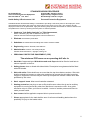
Health Safety & Environment 1.01
Personal Protective Equipment
Australian Mineral & Waterwell Drilling is committed to providing a safe work place for all employees, client
representatives and others with whom we interact during the course of our work. The company and all
employees shall so far as practicable, apply the following steps to Eliminate hazards or reduce hazards to an
acceptable level. There by ensuring the work place as safe as possible.
1. Conduct a "Job Safety Analysis" or "Risk Assessment,
before undertaking any task to determine what if any
hazards exist and what the appropriate control measures are.
2. Eliminate the hazard if practicable.
3. Substitute the hazard with something that creates a lesser hazard.
4. Engineering controls. Guards, barricades etc.
5. Administrative controls. Job safety analysis,
"Written Work Instructions," signage, training, etc.
6.
PERSONAL PROTECTIVE EQUIPEMENT. (PPE)
The minimum PPE worn on an operating drill site is:
1. Hard Hat of approved type. Wide brims and neck flaps should be fitted to hard hats to
reduce exposure to the sun.
2. Safety glasses clear or tinted with side shields. Prescription lens glasses shall be fitted
with side shields.
3. Shirt with collar. Shirts shall have no more than the top three buttons undone. Shirt tails
shall be tucked into trousers or other wise restrained to prevent the shirt tails becoming
caught on equipment. Sleeves may be rolled up to expose the forearm unless other wise
prohibited by site rules.
4. Steel- capped boots. Must meet Australian standard.
5. Hearing protection (ear plugs or ear muffs) shall be worn when the rig and or ancillary
equipment is running and at any other time that there is excessive noise. As a guide
excessive noise is; when you have to be within 1 metre of another person and shout to
make yourself heard.
6. Sun screen shall be applied to exposed skin to prevent sun burn.
7. Gloves appropriate for the task shall be worn for all manual handling tasks where the
possibility of injury to the hands exists.
8
STANDARD WORK PROCEDURE
No: SURHSE 1.01
Title: Personal Protective Equipment
Revision Date: 8th Oct. 2010
Prepared By: Vaughan Cullen
Approved By: Vaughan Cullen
Reviewed By: Lawrie Lorrigan
Health Safety & Environment 1.01
Personal Protective Equipment
8. .Dust masks shall be worn when.
1. Mixing mud that is in powdered form and or gives off dust during the mixing process.
2. Mixing cement,
3. When drilling with air if mechanical or other dust suppression equipment does
not eliminate the dust hazard.
4. At any time when dust causes a hazard or when directed by site rules or your
supervisor.
10. Full body harness and Ianyard attached to a secure anchor point. Or attached to a fall
arrest device that is attached to a secure anchor point.
Shall be worn when working at heights where a fall could cause injury. (Currently 2m.)
And or where a fall onto the surface below could cause injury. And or as required by site
rules. And or as directed by your supervisor.
11. When working in cold weather, care shall be taken to ensure that clothing worn to keep
warm is not allowed to be so loose fitting as to create a hazard. lf practicable, cold weather
clothing should be worn under overalls.
12. When working in wet weather and wearing rain coats and or wet weather trousers extra
care shall be taken and the work routine adjusted to ensure that the job is carried out
safely.
13 Other PPE as directed by clients, supervisors or management may be required on some
work sites. IE Disposable overalls, high visibility clothing, barrier cream, etc.
14. Care & Maintenance. Personal protective equipment is supplied for your safety and is to
be used for your protection.
IT IS YOUR RESPONSIBILITY TO;
1 Wear the correct PPE for the job you are doing.
2 Look after your PPE, keep it clean, in good repair.
3. Store your PPE safely when not in use.
4 Report any wear and tear, loss or damage to your supervisor.
Personal Protective Equipment is the final line of defence to prevent personal injury in the
work place. It is our responsibly to use the correct PPE for the task and ensure that those
working with us also use the correct PPE.
If in any doubt ASK! Your driller or supervisor.
9
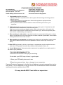
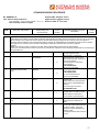
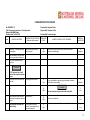
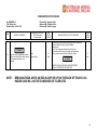
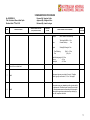
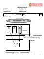
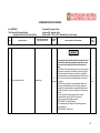
Document
Number
aligned
with index
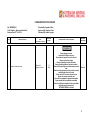
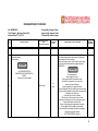
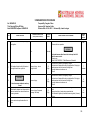
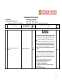
“Title” describes
what the specific
task is. Ie
Raising Mast
UDR1000
Revision Date to check this is
the most up to date SWP and it
has been revised
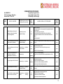
STANDARD WORK PROCEDURE
No: SURHGEN 2.08
Title: Raising Mast UDR 1000
Revision Date: 13th March 2009
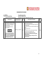
STEP
SPECIFIC JOB STEPS
Prepared By: Vaughan Cullen
Approved By: Vaughan Cullen
Assessment Team Members: Vaughan Cullen
HAZARDS WITHIN THIS STEP
(Safety and Environment)
RISK LEVEL
SCORE
This heading Details who was
involved in the process of
preparing, approving and carrying
out the risk assessment for this
SWP.
HAZARD CONTROL ACTIVITY REQUIRED
RESIDUAL RISK
SCORE
1
2
3
4
5
6
7
8
9
10
11
12
Step by step
details of the job or
task
Identify ALL the
hazards in each
step
Score before
hazard control
measures and /or
activities have
been completed
Details of Hazard control
measures, activities and/or
equipment required.
Score after hazard
control measures
have been
implemented.
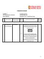
10
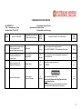
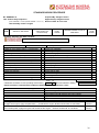
No:
Title:
Revision Date:
STEP
Prepared By:
Approved By:
Assessment Team Members:
SPECIFIC JOB STEPS
HAZARDS WITHIN THIS STEP
(Safety and Environment)
RISK LEVEL
SCORE
HAZARD CONTROL ACTIVITY
REQUIRED
RESIDUAL RISK SCORE
1
2
3
4
5
6
7
11
No:
Title:
Revision Date:
STEP
Prepared By:
Approved By:
Assessment Team Members:
SPECIFIC JOB STEPS
HAZARDS WITHIN THIS STEP
(Safety and Environment)
RISK LEVEL
SCORE
HAZARD CONTROL ACTIVITY
REQUIRED
RESIDUAL RISK SCORE
8
9
10
12
STANDARD WORK PROCEDURE
No: SURHSE1.02
Title: Manual Handling
Revision Date: 8th Oct. 2010
STEP
Prepared By: Vaughan Cullen
Approved By: Vaughan Cullen
Reviewed By: Lawrie Lorrigan
HAZARDS WITHIN THIS STEP
(Safety and Environmental)
SPECIFIC JOB STEPS
RISK
LEVEL
SCORE
HAZARD CONTROL ACTIVITY REQUIRED
RESIDUAL
RISK
SCORE
CAN THIS LIFT BE CONDUCTED WITHOUT MANUAL HAJNDLING
1
21
High
Assess weight and size of load.
Injury due to excessive
weight awkward size or
shape of load.
Complete inductions 5
Complete a JSA on task if not a standard work procedure. SWP
SURHSE 1.01 PPE
Team lift or mechanical lift heavy, awkward loads. Complete warm up
and stretching exercises prior to commencing task
Ask for assistance
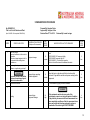
WARNING
5
Low
READ SAFE LIFTING PROCEDURE BELOW
2
Complete warm up stretching
exercises prior to lifting
3
Position feet correctly, shoulder
width apart. Stand close to load,
don’t over reach.
4
Bend knees and keep back
straight.
Take a firm grip using the base of
your hand
5
6
Lift Head, tuck chin in
7
Lift smoothly using leg muscles,
keeping back straight
8
Keep load close to body
9
When handling rods, grip with arms
spread at a comfortable distance
and thumbs facing the same
direction
10
Make sure load is evenly balanced
11
Do not twist your body when lifting
– turn by using your feet.
Ensure Signage is in Place
13
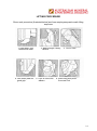
LIFTING PROCEDURE
Show work procedure (illustrated below} and have employees practice safe lifting
sequence
1. Feet apart, one
behind the other
4. Use entire palm for
good grip
2. Back straight, nearly
vertical
5. Tuck in arms and
elbows
3. Tuck in chin
6. Start lifting with push
from rear foot
14
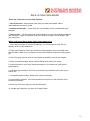
SAFE LIFTING PROCEDURE
There are 3 reasons for most back injuries:
1. Size of the load - load may be more than your back can handle. Never
underestimate the size of a load.
2. Amount of strength — know what you can lift safely. Never overestimate your
strength.
3. How you lift — lift the wrong way, twist instead of turn, get into awkward positions
and use quick, rough, movements, and you’ll strain your back. Lift the proper, safe
way every time. ·
When performing lifting tasks, follow these basic rules:
1. First, test the weight of the load by tipping it. lf in doubt, ask for help. Do not
attempt to lift a heavy load alone.
2. Take a good stance. Plant your feet firmly with legs apart, one foot farther back
than the other. Make sure you stand on a level area with no oil spots or loose gravel,
etc.
3. Get a firm grip. Use as much of your hands as possible, not just your fingers.
4. Keep your back straight, almost vertical. Bend at the hips if you bend.
5. Hold load close to your body. Keep the weight of your body over your feet for
good balance.
6. Use large leg muscles to lift. Push up with the foot positioned in the rear as you
start to lift.
7. Lift steadily and smoothly. Avoid quick, jerky movements.
8. Avoid twisting motions. Turn the forward foot and point it in the direction of the
eventual movement.
9. Never try to lift more than you are accustomed to.
10. Always get help when you have to lift bulky loads.
15
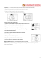
Unloading — To unload, face the spat you have chosen and lower the lead slowly
1. Bend your knees and let your legs, not your back do the work.
2. Keep your fingers away from the bottom and place
the load on the edge of the surface than slide it back
Lifting or lowering from a high plaza.
1. Stand on a sturdy ladder or platform. Never stand on the top rung.
2. Lift the wad in smaller pieces if possible if possible.
3. Push up on the load to see heavy and stable it is.
4. Slides the load as close to yourself as possible before lifting.
5. Grip firmly and slider it down
6. Get help, if needed, instead of taking risks by yourself. ·
Awkward objects.
1. Bend your knees with feet spread.
2. Grip the top outside and bottom inside corners.
3. User your legs to lift, keeping your back straight.
Warm up before you lift — bend and stretch gently to get ready.
THINK before you lift. Building a good lifting habit or breaking a bad one starts in your head
TURN. DON’T TWIST.
16
SAFETY TIPPING
AVOID TWISTING MOTIONS
TO: SUPEVISORS
Give a brief (1-2 minute) safety tip to your employees on how to avoid back injuries. One of the most
common causes of back injuries is twisting during a lift. By simply turning the forward
foot and pointing it in the direction of the eventual movement, you avoid the greatest danger of
injury from twisting.
When you are carrying a load and have to turn, don’t twist the upper part of your body, instead
make your entire body move around the corner or obstacle.
Remember to TURN, DON’T TWIST
THE TWIST IS OUT
When you’re carrying
a load and have to
turn, don’t twist the
upper part of your
body. Make your
entire body move
around the corner or
obstacle. Twisting is
the most common
cause of back injuries,
and the easiest to
avoid.
17
STANDARD WORK PROCEDURE
No: SURHSE1.03
Title: Housekeeping - Work Area
Revision Date: 8th Oct. 2010
STEP
SPECIFIC JOB STEPS
Prepared By: Vaughan Cullen
Approved By: Vaughan Cullen
Reviewed By: Lawrie Lorrigan
HAZARDS WITHIN THIS STEP
(Safety and Environmental)
RISK
LEVEL
SCORE
Identify walkways, work areas &
storage are clean and use safety
signs where applicable.
Personal injury and or
equipment damage.
24
High
Make sure walkways and work areas
are kept clear of trip hazards.
Personal injury and or
equipment damage.
22
High
Return tools to designated areas and keep walkways clear of cables,
hoses etc.
2
Low
20
High
Dig drainage channels. Use pallets, walkboards or gravel
High for sate working surface.
Fill in holes, pick up tools, rocks etc that may cause an
injury.
SWPHSE 1.02 Manual Handling
2
Low
12
Moderate
SWPHSE 1.02 Manual Handling
Moderate Cover section with dirt that may be walked over all the
time.
2
Low
4
Low
3
4
Make sure walkways and work areas
are kept dry.
Personal injury — slip hazard
due to wet areas.
Make sure all hoses are laid out
neatly and in a manner as to
minimize traffic over them time.
Personal injury
5
Low
Clean up spillage of oils & drill mud’s
etc.
Personal injury — slip hazard
17
Moderate
Use rags/truck wash to remove spillage refer M. S. D. S.
Environmental procedures
Spill kits are accessible if required
Chemicals are stored according to their MSDS
Fuel tanks are labelled and stored correctly.
Clean decking and tools at end of
shift.
Personal injury — slip hazard.
Equipment Damage
22
High
Clean tools/Work platform with rags banister brush and
truck wash.
5
Low
20
High
Place rubbish in bin.
High Follow safe manual handling procedure
SVVPHSE 1.02 Manual Handling
All rubbish to be secured for transport
As per site and environmental procedure.
5
Low
5
6
RESIDUAL
RISK
SCORE
Pre-start Inspections
Wear safety equipment, store equipment in designated areas and
obey safety signs.
Ensure all safety signs are in place
Ensure walkways have adequate safety rails and handles.
Ensure steps and ladders are secure and handles fitted where
needed.
Use it then replace it.
1
2
HAZARD CONTROL ACTIVITY REQUIRED
7
Place all rubbish in container/ bin and
remove from site at end of shift
Personal injury — trip hazards Manual
- Handling
18
STANDARD WORK PROCEDURE
No: SURHSE1.04
Title: Housekeeping - Tools
Revision Date: 8th Oct. 2010
STEP
1
2
3
SPECIFIC JOB STEPS
Prepared By: Vaughan Cullen
Approved By: Vaughan Cullen
Reviewed By: Lawrie Lorrigan
HAZARDS WITHIN THIS STEP
(Safety and Environmental)
Designate specific storage areas
or rack for specific tools.
Make sure these areas are safe
Trip hazard
Make sure storage area is close
to where tools will be most
frequently used.
Personal injury –
Fatigue/strain
Clean tools and return to
designated storage areas.
Personal injury
RISK
LEVEL
SCORE
HAZARD CONTROL ACTIVITY REQUIRED
RESIDUAL
RISK
SCORE
21
High
Return all equipment to designated areas.
Refer to SWP SURHSE 1.03 Housekeeping Work Area
5
Low
18
Moderate
Ensure everyone is aware of designated storage areas.
Onsite rig induction. ·
2
Low
Use rags/truck wash to clean tools.
Refer MSDS.
4
Low
21
High
Replace or repair as necessary.
4
WARNING
Check tools for damage.
Personal injury.
Equipment damage.
18
Moderate
Tag out equipment that is faulty
Electrical tools Slings and Lifting Gear must have
current inspection tag.
lf they need repair they must be tagged out and either
repaired by qualified trades person or discarded.
4
Low
19
STANDARD WORK PROCEDURE
No: SURHSE1.05
Title: Lock Out all Vehicles and Plant
Prepared By: Vaughan Cullen
Approved By: Vaughan Cullen
Revision Date: 8th Oct. 2010
Reviewed By: Lawrie Lorrigan
(Note: SURHSE 1.05 has replaced SURHSE 106)
STEP
SPECIFIC JOB STEPS
1
Shut down engine.
Ensure all controls are in the neutral or
off position.
Allow turbo charged engines to idle for
five minutes before shutting down.
Handbrake on
2
RISK
LEVEL
SCORE
HAZARD CONTROL ACTIVITY REQUIRED
RESIDUA
L RISK
SCORE
Equipment damage
16
Moderate
Compressors bleed off the stored air and isolate before starting any
work.
SWP SURAlR 3.01 Compressor Safety
SWP SURAIR Compressor Start UP
SWP SURHSE 1.10 Vehicle Daily inspection
Refer to Vehicle/Plant manual for additional information
5
Low
Personal injury operating
isolated equipment.
16
Moderate
Keep the key in a safe place until the lock can be safely
removed. A tag shall be used for each person working on the
equipment.
5
Low
HAZARDS WITHIN THIS STEP
(Safety and Environmental)
Remove ignition key
If there is no ignition key go to step 3
3
WARNING
Turn battery isolator to off position
and place personal danger tag and
padlock on isolator switch.
4
Positive test isolation.
4 Test isolation by trying to start the machine.
5
WARNING
Testing
Personal injury
Equipment damage
20
High
lf the equipment needs to be run as part of the
maintenance or service or during the period of isolation.
A tag shall only be removed after a risk assessment has
been completed, conditions of the risk assessment have
been met and the risk has been reduced to as low as
practicable. lf the risk is high DO NOT PROGEED.
4
Low
20
No: SURHSE1.05
Title: Lock Out all Vehicles and Plant
(Note: SURHSE 1.05 has replaced SURHSE 106)
STEP
SPECIFIC JOB STEPS
Prepared By: Vaughan Cullen
Approved By: Vaughan Cullen
Revision Date: 8th Oct. 2010 Reviewed By: Lawrie Lorrigan
HAZARDS WITHIN THIS STEP
(Safety and Environmental)
RISK
LEVEL
SCORE
HAZARD CONTROL ACTIVITY REQUIRED
RESIDUAL
RISK
SCORE
6
WARNING
Remove personal danger tag.
12
Moderate
Only remove lock and personal danger tag when it is safe to
do so. Or at the end of your shift, or you are no longer
working on that machine. lf the machine is still not in a safe
condition to operate when you remove your personal danger
tag Place an out of service tag on the machine battery
isolator.
Don’t forget to remove your personal danger tag and
replace it with an out of service tag if machine is still
defected at end of shift.
5
Low
21
STANDARD WORK PROCEDURE
No: SURHSE1.07
Title: Isolation Procedures Compressor
Revision Date: 8th Oct. 2010
STEP
SPECIFIC JOB STEPS
Prepared By: Vaughan Cullen
Approved By: Vaughan Cullen
Reviewed By: Lawrie Lorrigan
HAZARDS WITHIN THIS STEP
(Safety and Environmental)
RISK
LEVEL
SCORE
HAZARD CONTROL ACTIVITY REQUIRED
RESIDUAL
RISK
SCORE
SWP SURAIR 3.01 Compressor Safety
SWP SURAIR 3.02 Compressor Start Up
1
Shut Compressor down
2
WARNING
A HIGH PRESSURE AIR IS DANGEROUR AND CAN
RESULT IN DEATH.
Bleed off any built up pressure
3
Switch battery isolator key to off
position
Noise, dust, high pressure air
21
High
Refer to Operators manual
SVVP SURAIR 3.01 Compressor Safety
SVVP SURAIR 3.02 Compressor Start Up
Wear appropriate PPE
Signage and awareness of no go areas.
Do not allow any body part to be in the path of the high
pressure air as in vents
SV\/P SURHSE 1.05 Isolation Lockout
5
Low
WARNING
Turn battery isolator to off position and place personal
danger tag on isolator switch.
4
WARNING
Place isolation Tag over battery
Isolator.
If the equipment needs to be run as part of the maintenance
or service or during the period of isolation. A tag shall only
be removed after a risk assessment has been completed,
conditions of the risk assessment have been met and the
risk has been reduced to as low as practicable. lf the risk is
high DO NOT PROCEED.
22
STANDARD WORK PROCEDURE
No: SURHSE1.07
Title: Isolation Procedures Compressor
Revision Date: 8th Oct. 2010
STEP
SPECIFIC JOB STEPS
Prepared By: Vaughan Cullen
Approved By: Vaughan Cullen
Reviewed By: Lawrie Lorrigan
HAZARDS WITHIN THIS STEP
(Safety and Environmental)
RISK
LEVEL
SCORE
HAZARD CONTROL ACTIVITY REQUIRED
RESIDUAL
RISK
SCORE
5
WARNING
When job or task is completed
remove all tags.
Ensure personnel to remove
only their locks and no one
else’s.
20
High
Only remove personal danger tag when it is safe to do so.
Or at the end of your shift, or you are no longer working on
that machine. If the machine is still not in a safe condition to
operate when you remove your personal danger tag. Place
an out of service tag on the machine battery isolator.
5
Low
6
Switch Isolation on
7
Before starting compressor
ensure crew is clear of machine.
Any thing loose or undone
could become a flying object
Uncontrolled release of high
pressure air.
17
Moderate
SWP SURAIR 3.01 Compressor Safety
SWP SURAIR 3.02 Compressor Start Up
Wear appropriate P.P.E
Pre—start inspections
Signage and awareness of no go areas.
Do allow any body part to be in the path of the high pressure
air IE; as in vents
Maintain visual contact of all crew members ensure they are
in a safe area.
5
Low
23
STANDARD WORK PROCEDURE
No: SURHSE1.08
Title: Shift Change and Cross Shift Handover
Prepared By: Vaughan Cullen
Approved By: Vaughan Cullen
Revision Date: 8th Oct. 2010 Reviewed By: Lawrie Lorrigan
(Note: SURHSE 1.08 has replaced SURHSE 1.09)
STEP
1
2
3
4
SPECIFIC JOB STEPS
HAZARDS WITHIN THIS
STEP (Safety and
Environmental)
RISK LEVEL
SCORE
RESIDUAL
RISK SCORE
Prior to leaving drill site ensure rig and
ancillary equipment has been re fuelled.
Equipment damage breakdown
17
Moderate
Compliance with
Refuelling engines
SWP SURGEN 2.02 Refuelling Engines
5
Low
Clean and return to their designated area
all tools that have been used during the
shift.
Ensure all housekeeping duties have been
met.
Personal injury faulty tools
17
Moderate
SWP SURHSE 1.03 Housekeeping Work Area
SWP SURHSE 1.04 Housekeeping Tools
Read MSDS on chemicals if being used for cleaning.
5
Low
Gloves
SWP SURHSE 1.02 Manual Handling.
SWP SURGEN 2.19 Stilson Use.
Have at least six rods, cleaned, greased
and ready to go.
Day shift carry out pre start on lighting
Plant and start ready for night shift.
Two man lift
Use correct manual handling procedures
Gloves I
SWP SURHSE 1.02 Manual Handling.
8
Moderate
17
Moderate
Strictly adhere to Company report writing procedures and
practices. When in doubt ask Supervisor.
8
Moderate
17
Moderate
Ensure the last core block is marked up and is in the
correct place in the core tray.
Wear correct PPE - gloves. Follow client instructions for
correct mark up of tray.
Place empty core tray on racks suitable for the weight of
core and to minimize manual handling of crew and client
Ensure legible writing
Ensure tray is clean of contain aments.
SWP SURDIA 5.08 Empty Core Tubes and Wash Core.
8
Moderate
5
6
HAZARD CONTROL ACTIVITY REQUIRED
Load core on to light vehicle.
If required by client
Personal injury lifting –strain
back
Ensure all paper work has been filled out
correctly
Incorrect in formation
recorded.
20
High
7
Mark up the next 5 core trays
Incorrect in formation
recorded.
24
STANDARD WORK PROCEDURE
No: SURHSE1.08
Title: Shift Change and Cross Shift Handover
(Note: SURHSE 1.08 has replaced SURHSE 1.09)
STEP
SPECIFIC JOB STEPS
Prepared By: Vaughan Cullen
Approved By: Vaughan Cullen
Revision Date: 8th Oct. 2010 Reviewed By: Lawrie Lorrigan
HAZARDS WITHIN THIS STEP
(Safety and Environmental)
RISK LEVEL
SCORE
10
11
Fill mud tank and mix mud
Personal injury lifting - strain
Chemical burns and eye injury
20
High
Ensure the site is clean and tidy
. Environment- pollution
17
High
Rubbish correctly disposed of or securely loaded on to light
vehicle.
Obtain copy of Hand Over Sheet
The cross shift hand over sheet is
used b crew members and
personnel responsible for the rig
that they are working on.
Unable to find Hand Over Sheet
Transferring incorrect information to
cross shift
Write a list of parts and
Consumables needed for next shift.
Any other requirements of client,
supervisor or driller.
Incorrect information recorded
20
High
Strictly adhere to Company report writing procedures and
practices.
8
Moderate
Drive to accommodation or
designated shift change area.
Personal injury — vehicle
accident not driving to conditions.
not being clearly visible to other
traffic.
20
High
Ensure hazard signs in place and hazard lights operating.
Drive to conditions. Meet with cross shift and supervisor.
High Ensure licensed for the vehicle being driven.
5
Low
Change over with next crew.
Incorrect information being given
leading to contract and performance
error.
Personal injury due to wrong
instructions being given.
17
Moderate
Briefly describe the shifts activities, highlight any problems
that you had and how they were overcome. Pass on all
relevant information. Hand over list of parts and
consumables required
5
Low
Travel to drill site
Equipment Damage
17
Moderate
Carry out pre start on light vehicle.
Load and secure stores
Drive to conditions
3
Low
12
13
14
RESIDUAL
RISK
SCORE
Use correct manual handling procedures.
High Wear specified PPE as per MSDS sheets
Ensure walkways and ladders are secure and in place.
SWP SURHSE 1.02 Manual Handling. ‘
SWP SURMUD 2.17 Mix Mud.
8
9
HAZARD CONTROL ACTIVITY REQUIRED
5
Low
3
Low
Spare copy’s located in site office
16
Moderate
Transfer the correct information to your cross shift at shift
change meetings.
5
Low
25
STANDARD WORK PROCEDURE
No: SURHSE1.08
Title: Shift Change and Cross Shift Handover
(Note: SURHSE 1.08 has replaced SURHSE 1.09)
STEP
SPECIFIC JOB STEPS
HAZARDS WITHIN THIS STEP
(Safety and Environmental)
15
Arrival at Drill Site
Prepared By: Vaughan Cullen
Approved By: Vaughan Cullen
Revision Date: 8th Oct. 2010
Reviewed By: Lawrie Lorrigan
Equipment damage
RISK LEVEL
SCORE
17
Moderate
HAZARD CONTROL ACTIVITY REQUIRED
Park Light vehicle safely and check drill site.
Carry out pre start checks.
Start Drilling.
RESIDUAL
RISK
SCORE
3
Low
26
STANDARD WORK PROCEDURE
No: SURHSE1.10
Title: Vehicle Daily Inspection
(Note: SURHSE 1.10 has replaced SURHSE 1.11 & 1.12)
Prepared By: Vaughan Cullen
Approved By: Vaughan Cullen
Revision Date: 8th Oct. 2010
Reviewed By: Lawrie Lorrigan
STEP
1
SPECIFIC JOB STEPS
HAZARDS WITHIN THIS
STEP (Safety and
Environmental)
RISK
LEVEL
SCORE
Ensure vehicle is isolated before
going through check list
Checking engine oil
Hot oil
Oil Spillage
8
4
RESIDUA
L RISK
SCORE
Light Vehicle Daily inspection ( Vehicle Pre start): l
At the start of every shift a pre-start will be conducted and all findings recorded in the Pre start book. The top copy of the report
will be handed to your supervisor and any defects reported before going underground The purpose of the pre-start is to
determine that the vehicle is safe to operate and that any defects are repaired before the vehicle becomes unsafe to operate.
Thus keeping your vehicle in good condition, eliminating incidents and downtime due to unsafe conditions.
Vehicles:
AMWD has numerous types of vehicles in its fleet; these vehicles differ in there servicing requirements.
Ensure you consult the service manual, supervisor or maintenance supervisor for the servicing requirements for the vehicle you
are responsible for.
2
3
HAZARD CONTROL ACTIVITY
REQUIRED
Checking clutch & Brake
Fluid
Spillage
8
Allow engine to cool before
checking oil Use a clean rag to
wipe oil from dip stick. Use funnel
top up oil if required
Consult operator’s manual for
correct oil type.
IF IN DOUBT ASK!
Clean up as per MSDS
Consult operator’s manual for
correct type of fluid.
IF IN DOUBT ASK!
Do not over fill reservoirs.
Clean up as per MSDS
5
6
7
8
Checking Coolant level
Checking vee Belts
Checking Hoses and fuel
lines
Checking Undercarriage
8
Do not remove radiator cap if
engine is hot.
Check fluid level in the expansion
bottle, do not overfill passed the
full level.
Use correct type of coolant.
IF IN DOUBT ASK!
4
Allow engine to cool if hot.
Visually check vee belts for wear.
Check operator’s manual for
correct tension and instructions.
8
Allow engine to cool. Visually
check hoses and fuel lines for
leaks.
Hot Coolant
Burns
Hot engine parts
Hot engine parts
Check Chassis for cracks and
excess rust check brake lines and
fuel lines for leaks. Inspected
springs and shock absorbers for
defects. Under
l carriage should be clean and free
of mud
27
STANDARD WORK PROCEDURE
No: SURHSE1.10
Title: Vehicle Daily Inspection
(Note: SURHSE 1.10 has replaced SURHSE 1.11 & 1.12)
Prepared By: Vaughan Cullen
Approved By: Vaughan Cullen
Revision Date: 8th Oct. 2010
Reviewed By: Lawrie Lorrigan
STEP
HAZARDS WITHIN THIS
STEP (Safety and
Environmental)
SPECIFIC JOB STEPS
RISK
LEVEL
SCORE
RESIDUA
L RISK
SCORE
HAZARD CONTROL ACTIVITY
REQUIRED
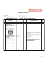
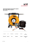
Example: Operator Pre-Start Checklist
OPERATOR PRE-START CHECKLIST
LIGHT VEHICLES
Unit No. Lv00084
Operator: Nicu. J
Date: 12/5/06
Shift; Day
Engine Off
Check for out of service tags or personal tags
Check horn operation
Check Vee Belts
Check engine oil pressure
Check Engine Oil Level
Check steering operation
Check Coolant level (if cold)
Check gauges and indicator lights
Check air filter indicator and filter assembly
Check operation radios
Check exhaust ducting and connections
Check jack
Check all hoses and fuel lines visually
Check wheel brace
Check all components for oil leaks
Check spare tyre
Check tyres and wheel nuts
Check springs front and back
Check fire extinguisher
Check reverse beeper
Check fuel level
Check reverse light
Check tyre pressure
Check beacon light
Check for first aid kit
Check Strobe light
Check seat belt condition
Check high beam
Check condition of seats
Check low beam
Hour Metre Reading 149366
Tick for standard (O.K.)
For Substandard (U/S)
POOR
N/A
OK
Cleanliness Condition of Cab (including windscreens)
Record Odometer reading
Report all defects I substandard conditions immediately to shift supervisor / fitter.
Defects/Substandard Conditions (if any)
Is Vehicle safe to operate YES / NO
Operator’s Signature:
Card checked and all defects have been rectified
Signed
(Project Mechanical superintendant or nominee)
Date & Time
/ /
am/ pm.
Parking Brake Test
Engage second gear, apply the park brake — Accelerate the engine. Brakes should hold at 175O RPM
RECORD
Passed
Service Brake Test
Press brake pedal, engage first gear and accelerate the engine — Brakes should hold at 1750 RPM
RECORD
Passed
28
STANDARD WORK PROCEDURE
No: SURHSE1.13
Title: Operating Salamander Heater
Revision Date: 8th Oct. 2010
STEP
1
2
SPECIFIC JOB STEPS
HAZARDS WITHIN THIS STEP
(Safety and Environmental)
All flammable materials (paper/rags
etc) in drill shacks (sheds) are to be
removed prior to lighting
Personal injury bums
Equipment damage fire
Ensure unit is on a level base
Manual handling injuries
3
Ensure flue is firmly secure
4
Ensure filter cap/vent is serviceable
5
Fill Fuel Bowl to approximately 80 %
6
Ensure butterfly V/V is latched
open
7
Light Unit
8
V\/hen unit is lit close cap/vent
ensuring 3 vent openings are visible
V\/hen shutting down —- half an
hour prior to end of shift, ensure
butterfly valve and vents are closed
9
Prepared By: Vaughan Cullen
Approved By: Vaughan Cullen
Reviewed By: Lawrie Lorrigan
WARNING
RISK LEVEL
SCORE
HAZARD CONTROL ACTIVITY REQUIRED
RESIDUAL
RISK SCORE
25
High
Ensure that area ls clear of all potential fire hazards prior to
lighting.
Ensure tire extinguisher is readily available and has been
Serviced.
7
Moderate
22
High
Use correct manual handling techniques
SVVP SURHSE 1.02 Manual handling
4
Low
Adhere to environmental procedures on spillages
Read MSDS on diesel and follow its handling instructions
Hand injuries
11
Moderate
Hand injuries
20
High
Wear Gloves
4
Low
Wear gloves and eye protection
4
Low
NEVER REFILL OR RELIGHT
SALAMANDER IF IT IS BURNING
OR IS HOT FROM USE.
ALLOW TO COOL
10
Cleaning Salamander
Ensure salamander ls cold
Follow MSDS and environmental procedures for disposal of
waste materials
PPE gloves eye protection and dust mask.
29
STANDARD WORK PROCEDURE
No: SURHSE1.14
Title: Chemical Handling
Revision Date: 8th Oct. 2010
Prepared By: Vaughan Cullen
Approved By: Vaughan Cullen
Reviewed By: Lawrie Lorrigan
HAZARDS WITHIN THIS STEP
(Safety and Environmental)
RISK LEVEL
SCORE
Prepare to use chemicals,
Before using any chemical, ensure
the Material Safety Data Sheet
(MSDS) has been read thoroughly.
Personal injury non-compliance
with MSDS information. Burns,
chemical inhalation.
20
High
2
Select and fit PPE
Personal injury non-compliance
with MSDS information. Burns
3
Select correct applicator
Personal injury non-compliance
with MSDS information. Burns
16
Moderate
4
Use with other chemicals
Personal injury non-compliance
with MSDS information. Burns
20
High
5
Apply chemical
Personal injury non-compliance
with MSDS information. Burns
16
Moderate
6
Clean up
Personal injury non-compliance
with MSDS information. Burns,
chemical inhalation.
16
Moderate
7
Disposal of ‘used’ containers and
contaminated PPE
STEP
1
SPECIFIC JOB STEPS
Personal injury.
Environmental Damage.
20
High
20
High
HAZARD CONTROL ACTIVITY REQUIRED
lf any doubts exist, ask the supervisor for advice in the use
of the chemical, handling and the correct Personal
Protective Equipment (PPE) to be worn.
Ensure you have adequate PPE (eg. Wet weather gear,
Respirator, Gloves etc., if necessary) so that no direct skin
contact occurs or dangerous vapours are inhaled. Apply
medicated skin cream to any exposed areas if required.
Ensure the correct applicator is used, such as a spray bottle
or other devices to ensure the chemical is correctly applied
to the equipment.
Ensure there ls no “mixing" of any chemicals, unless the
MSDS and/or instructions advise it is safe to do so.
Apply the chemical to the equipment and wall for the
specified reaction to take place.
When finished with the chemical ensure it is stored in a safe
place. When removing correct PPE, ensure there is no skin
contact with the chemical and wash PPE with clean water
only. Follow MSDS
Dispose of ‘used' containers according to local, mine site or
state regulations and MSDS.
RESIDUAL
RISK SCORE
10
Moderate
8
Moderate
8
Moderate
8
Moderate
5
Low
5
Low
8
Low
30
STANDARD WORK PROCEDURE
No: SURHSE1.15
Title: Travelling Between Sites in Remote Areas
Revision Date: 8th Oct. 2010
Prepared By: Vaughan Cullen
Approved By: Vaughan Cullen
Reviewed By: Lawrie Lorrigan
Vehicle suitability
Things to consider
ls the vehicle suitable for the route to be travelled?
ls it capable of safely carrying the required load and/or number of passengers?
Is it equipped with sufficient spare parts,wheels, first aid kit, water and emergency provisions
for the journey?
Is it equipped with a means of communication in the event of a breakdown?
Has the vehicle been maintained to a suitable standard that will provider reliability?
STEP
SPECIFIC JOB STEPS
1
After reading the above ensure
the five points can be achieved.
Service end check out vehicle and
ensure spare wheel, Jack, First aid
Kit, Spare parts Hand tools,
communication equipment water
and emergency provisions are in the
vehicle. Lifting device for spare
tyres and trucks.
2
Advise necessary personnel and
supervisor route to be taken and
anticipated arrival time. Set up
schedule for phone calls
HAZARDS WITHIN THIS STEP
(Safety and Environmental)
Personal Injury
Back Injury
Incorrect tools
RISK LEVEL
SCORE
20
High
HAZARD CONTROL ACTIVITY REQUIRED
SVVP SURHSE 1.10 Vehicle inspection
Correct use of hand tools and correct size tools
Use lifting device for spare tyre
Carry Drinking water
Adhere to the five points of travel.
RESIDUAL
RISK SCORE
4
Low
WARNING
Ensure trip details are given to the necessary personnel
and the supervisor.
lf this can not be achieved then the closest AMWD
department must be notified.
Don’t change trip plans unless you have notified one of the
above.
Schedule Phone calls for long trips
31
STANDARD WORK PROCEDURE
No: SURHSE1.15
Title: Travelling Between Sites in Remote Areas
Revision Date: 8th Oct. 2010
STEP
SPECIFIC JOB STEPS
3
During the trip ensure reel breaks
are taken regularly and logbook is
filled in correctly. Drive according to
weather and road conditions. Make
phone calls at schedule times
4
HAZARDS WITHIN THIS STEP
(Safety and Environmental)
Motor Vehicle accident due to
fatigue
Prepared By: Vaughan Cullen
Approved By: Vaughan Cullen
Reviewed By: Lawrie Lorrigan
RISK LEVEL
SCORE
24
High
HAZARD CONTROL ACTIVITY REQUIRED
Ensure trip is planned and breaks are taken according to
national drivers Log book.
Drink plenty of water.
RESIDUAL
RISK SCORE
16
Moderate
On arrival inform necessary
personnel, supervisor or AMWD
office. Contact departure site to
advise of arrival.
WARNING
Read attached documents on
Remote Hazards
32
STANDARD WORK PROCEDURE
No: SURHSE1.15
Title: Travelling Between Sites in Remote Areas
Revision Date: 8th Oct. 2010
Prepared By: Vaughan Cullen
Approved By: Vaughan Cullen
Reviewed By: Lawrie Lorrigan
Remote Area Hazards
Consideration should be given lo the following points:
Roadtrains
These are common in the Northern Territory and can he up to three trailers (50 metres} long. They
are not confined to the bitumen and will be encountered on dirt roads. Always give them plenty of
room and when overtaking, allow all least l km of clear road ahead.
Dust on outback roads can obscure a driver’s vision. Take great care if overtaking.
Wandering stock and wildlife
The majority of Northern Territory roads are not fenced. Cattle horses, kangaroos, donkeys,
buffaloes and even camels may be found crossing the roads particularly early in the morning and
late in the afternoon. They may also be found standing in the middle of the road al night. Drivers
should slow down and treat all animals on the road or roadside with caution. Do not expect
animals to automatically move out of the way. Birds may also be a problem especially if they are
feeding on the bodies of other animals killed on the road.
33
STANDARD WORK PROCEDURE
No: SURHSE1.15
Title: Travelling Between Sites in Remote Areas
Revision Date: 8th Oct. 2010
Prepared By: Vaughan Cullen
Approved By: Vaughan Cullen
Reviewed By: Lawrie Lorrigan
Night driving
Night driving should he avoided if at all possible. However it night driving is necessary, the vehicle
should he checked to ensure its lights are adequate. A driver required to travel at night should be
reminded to reduce his/her speed so that he/she can stop safely if required to do so in an emergency.
Driver fatigue
The driver should he reminded that it he/she feels tired or drowsy they should stop driving and have a
break, Breaks of 10 minutes or so should be taken every 3 hours in any case. Driver fatigue is one
of the most common causes of single vehicle accidents.
Floods
The driver should he instructed not to attempt to cross flooded bridges or causeways unless they are
absolutely sure of the depth of water over the road and know if there are any submerged obstacles or
road damage. Drivers should also be aware of the danger that swift flowing water presents. Most
flash floods recede within 24 hours. Listen to radio reports in the wet season.
Breakdowns
in the event of a breakdown the driver should be instructed to stay with the vehicle and be reminded
that a missing vehicle is much easier to find than a missing person. As temperatures in the Territory
can be in both extremes, it is important to remind the driver to stay in the shade or under shelter.
Employers and drivers should also ensure that prior to departing there is an ample supply of water in
the vehicle.
Service and fuel
Prior to departing drivers must be given information on the availability of fuel and vehicle repair
outlets such as opening times, distances, location and credit card facilities.
34
STANDARD WORK PROCEDURE
No: SURHSE1.16
Title: Emergency procedures – Gas Intersection
Diamond and Mud Rotary
Revision Date: 8th Oct. 2010
STEP
SPECIFIC JOB STEPS
1
Stop drilling – Leave pump running
at same speed
2
Note exact depth of hole and exact
time of day and advise Supervisor
3
Notify client representative and
supervisor
HAZARDS WITHIN THIS STEP
(Safety and Environmental)
Prepared By: Vaughan Cullen
Approved By: Vaughan Cullen
Reviewed By: Lawrie Lorrigan
RISK LEVEL
SCORE
HAZARD CONTROL ACTIVITY REQUIRED
RESIDUAL
RISK SCORE
Gas bubbles may be flushed
back to surface
25
High
Shut down any ignition source around bore hole collar and
observe no smoking signs.
12
Moderate
24
High
If only small bubbles of gas emerging as circulated to surface it
will be safe to resume drilling.
8
Moderate
4
WARNING
DO NOT approach the rig until
detectors are available to monitor
the gas
5
Monitor gas around bore collar and
work area
Escaping gas fire explosion
6
Stop pump and pull inner tube from
hole
Swabbing hole
20
High
7
Remove shut off valves from inner
tube backend and replace with steel
spacers.
Personal injury
20
High
8
Pump inner tube to bottom and
resume drilling.
Small bubbles of gas may
continue to be circulated out of
hole with drilling fluid
21
High
WARNING
Pull tube slowly and top up annulus with drilling fluid.
Correct use of hand tools
Use bug blower to control ventilation around drill hole collar
4
Low
7
Low
7
Low
35
STANDARD WORK PROCEDURE
No: SURHSE1.16
Title: Emergency Procedures – Gas Intersection
Diamond and Mud Rotary
STEP
9
SPECIFIC JOB STEPS
Continue drilling as normal
under the controlled conditions.
HAZARDS WITHIN THIS STEP
(Safety and Environmental)
Prepared By: Vaughan Cullen
Approved By: Vaughan Cullen
Revision Date: 8th Oct. 2010 Reviewed By: Lawrie Lorrigan
RISK LEVEL
SCORE
HAZARD CONTROL ACTIVITY REQUIRED
RESIDUAL
RISK SCORE
Continually inspect core for further signs of disking. Monitor
level of sumps for increased volume of water return that
could indicate that gas is pushing the fluid out of the hole.
Inform Supervisor and Client
Further gas intersections
WARNING
22
High
Continually monitor Gas readings throughout
hole. Ensure any tripping of rods, pulling of tubes,
survey equipment and orientation equipment the
annulus is being filled with water.
Ensure all ignition sources are kept at a minimum
10 meters from the collar.
36
STANDARD WORK PROCEDURE
No: SURHSE1.17
Title: Unpack New Rods
Revision Date: 8th Oct. 2010
STEP
SPECIFIC JOB STEPS
1
Ensure work area is free of hazards
2
Place roll stops.
3
Restrain binding strap
4
Cutting sequence.
Prepared By: Vaughan Cullen
Approved By: Vaughan Cullen
Reviewed By: Lawrie Lorrigan
HAZARDS WITHIN THIS STEP
(Safety and Environmental)
Personal Injury. Slip, trip
Personal Injury -lifting
RISK LEVEL
SCORE
HAZARD CONTROL ACTIVITY REQUIRED
RESIDUAL
RISK SCORE
Work area shall be level clear and free of hazards. Enough space
to allow rods to roll out 1 layer high when they are released from
the binding step. Work area may be the ground or a truck deck.
SWP SURHSE 1.03 Housekeeping Work area
Correct manual handling.
SWF SURHSE 1.02 Manual Handling
Roll stops can be star pickets driven into the ground. Blocks of
wood or other suitable items that will prevent the rods rolling in an
uncontrolled manner when the binding strap is cut.
Binding strep on each side of out shell be restrained by a heavy
object ie wooden block that shall prevent the cut ends of the
binding strep from moving in an uncontrolled manner when the cut
is made.
PPE: gloves, eye protection
If bundle has end caps remove these first. Cut the inner or middle
straps first, Cut end straps last and from a position beyond the end
of the rods, clear of the area where the rods have potential to roll
when the last binding strap is cut.
WARNING
ONCE CUT, THE RODS HAVE THE POTENTIAL TO ROLL
UNCONTROLLABLY. ENSURE SUFFICIENT CHOCKING
AND STAND A SAFE DISTANCE FROM STACK. 1
PEE; gloves, eye protection
37
STANDARD WORK PROCEDURE
No: SURHSE1.17
Title: Unpack New Rods
Revision Date: 8th Oct. 2010
STEP
5
SPECIFIC JOB STEPS
Prepared By: Vaughan Cullen
Approved By: Vaughan Cullen
Reviewed By: Lawrie Lorrigan
HAZARDS WITHIN THIS STEP
(Safety and Environmental)
RISK LEVEL
SCORE
HAZARD CONTROL ACTIVITY REQUIRED
RESIDUAL
RISK SCORE
Cutting tool such as side cutters or tin snips is best. A pair of
shifting spanners closed tight on strap. Handles opposing each
other in a near to horizontal position. Then handles bought up to
meet will also out the binding strap. A crow bar placed under the
strap and used as a lever will also break the strap while you are
standing at a safe distance.
Cutting Tool
WARNING
ONCE CUT, THE RODS HAVE THE POTENTIAL TO ROLL
UNCONTROLLABLY. ENSURE SUFFICIENT CHOCKING AND
STAND A SAFE DISTANCE FROM STACK.
PPE: gloves, eye protection
6
Cut binding strap.
Personal Injury – cuts. Rods
rolling uncontrolled when strap
is cut
Ensure strap of each side of cut is restrained. Ensure roll stops
are in place.
PPE: gloves, eye protection
7
Completion of Unpacking
Personal Injury. Lifting
Rods rolling
Ensure roll stops are secure. lf required move individual rods to
new location ready for use, Place out binding strap with rubbish for
later disposal.
Dispose of rubbish as per environmental and site procedures
38
STANDARD WORK PROCEDURE
No: SURHSE1.18
Title: Emergency procedures – Drill Rig Fire
Revision Date: 8th Oct. 2010
STEP
1
SPECIFIC JOB STEPS
HAZARDS WITHIN THIS STEP
(Safety and Environmental)
Prepared By: Vaughan Cullen
Approved By: Vaughan Cullen
Reviewed By: Lawrie Lorrigan
RISK LEVEL
SCORE
HAZARD CONTROL ACTIVITY REQUIRED
RESIDUAL
RISK SCORE
Stop rig operation, rotation, feed
water pump etc
Personal injury & equipment
damage
High pressure hydraulic oil
could fuel fire causing.
25
High
Shut down any ignition source.
Prepare fire breaks
Setup wash down hose
4
Low
2
Shut down drill rig
Personal injury radiant heat,
fumes, burns poor visibility
23
High
Endure all flammable substances are relocated out of fire path.
Ensure adequate fire breaks are implemented.
4
Low
3
Evacuate the immediate area
Personal injury radiant heat,
fumes, burns poor visibility
4
WARNING
23
High
Notify emergency response team,
client representative and/or fire
Clear area of all personnel to designated emergency
assembly area upwind from the fire.
Conduct head count
4
Low
Inform mine of emergency via radio in line with client emergency
procedures.
5
Extinguish Fire
Personal injury radiant heat,
fumes, burns poor visibility.
6
Re-entry of site following
extinguishing of fire
Personal and Equipment
Re ignition of tire tank
explosion.
7
Continuing drilling as normal
Equipment damage following
fire
24
High
Stay up wind do not open any closed coverings as this may cause
fire to develop particularly if fire is near the fuel tank.
Retreat to designated assembly area.
9
Moderate
24
High
Wait until site has been inspected by mines rescue or trained and
competent personnel.
8
Moderate
17
Significant
Continually inspect area and equipment for further signs of
damage or fire risk. Inform Supervisor.
4
Low
39
STANDARD WORK PROCEDURE
No: SURHSE1.19
Title: Emergency procedures – Gas Blowout
Revision Date: 8th Oct. 2010
STEP
1
SPECIFIC JOB STEPS
HAZARDS WITHIN THIS STEP
(Safety and Environmental)
RISK LEVEL
SCORE
HAZARD CONTROL ACTIVITY REQUIRED
RESIDUAL
RISK SCORE
Stop drilling - leave water pump
running at same speed
WARNING
Personal injury
Equipment Damage
IF SAFE TO DO SO. BLAST THE
HORN ON THE RIG NOTIFY
CREW AND EVACUATE THE
AREA IMMEDIATELY TO THE
DESIGNATED MUSTER POINT. 1
2
Prepared By: Vaughan Cullen
Approved By: Vaughan Cullen
Reviewed By: Lawrie Lorrigan
25
High
Note exact depth of hole, exact
time of day and the gas reading
that was recorded advise
Supervisor and client.
3
WARNING
Once Supervisor and/or client arrive
a risk assessment will be conducted
to assess the best way to monitor
the situation.
Conduct emergency procedure evacuation drills regularly.
One long loud blast on the horn would indicate gas levels
in the hole are at an unacceptable level and all crew need
to be evacuated to the muster point.
Muster point is 50 meters upwind from the rig
Conduct a head count
Ensure all signage is in place
Ensure all ignition sources are not within 10 meters of the
rig collar at all times
Ensure LEL gas monitors are serviced, charged and
calibrated as per manufactures instructions
Ensure all fire equipment is serviceable
Ensure Washington rubber is not leaking
Pre—Start Inspections
12
Moderate
Low warning level on gas monitor is set at 10 LEL or 0.5 %
High warning level on gas monitor is set at 50 LEL or 2.5%
Of gas in the atmosphere
Personal injury
Equipment Damage
25
High
Ensure all ignition sources are not within 10 meters of the rig collar
at all times.
Ensure LEL gas monitors are serviced, charged and calibrated as
per manufactures instructions
Conduct a head count.
lf gas is still being recorded on the monitor move further away
upwind.
Consider contacting emergency response team and fire brigade if
an explosion is imminent.
8
Moderate
40
STANDARD WORK PROCEDURE
No: SURHSE1.19
Title: Emergency procedures – Gas Blowout
Revision Date: 8th Oct. 2010
STEP
SPECIFIC JOB STEPS
4
Once safe to do so a nominated
person will monitor the gas readings
and record them on the gas sheets.
5
A heavy brew of drilling fluids will be
pumped down the hole
HAZARDS WITHIN THIS STEP
(Safety and Environmental)
Prepared By: Vaughan Cullen
Approved By: Vaughan Cullen
Reviewed By: Lawrie Lorrigan
RISK LEVEL
SCORE
HAZARD CONTROL ACTIVITY REQUIRED
RESIDUAL
RISK SCORE
A typical brew would consist of:
Barytes,Pac,Liquipol, Lithium gum,Gel,Safe lube or Seam drill
An example of mixing proportions would be;
Lithium gum 10 kg
Pac 5kg
Safe lube 1lts
Barites 35 kg
Per 1000lts
Or
Gel 10kg
Pac 5 kg
Liquipol 5 Its
Barites 35 kg
Per1000lts
Ensure all ignition sources are not within 10 meters of the rig collar
at all times
Ensure LEL gas monitors are serviced, charged and calibrated as
per manufactures instructions
Monitor gas levels whilst mixing mud.
SWP SURGEN 2.17 Mix Mud
41
STANDARD WORK PROCEDURE
No: SURHSE1.19
Title: Emergency procedures – Gas Blowout
Revision Date: 8th Oct. 2010
STEP
6
SPECIFIC JOB STEPS
Monitor gas around bore collar,
blooie line and work area
HAZARDS WITHIN THIS STEP
(Safety and Environmental)
Prepared By: Vaughan Cullen
Approved By: Vaughan Cullen
Reviewed By: Lawrie Lorrigan
RISK LEVEL
SCORE
Escaping gas fire explosion
24
High
7
Once gas levels return to normal
continue drilling under the controlled
conditions from the risk assessment
HAZARD CONTROL ACTIVITY REQUIRED
Continue gas monitoring
Look for change in gas levels once heavy drilling fluids have been
returned.
Ensure all ignition sources are not within 10 meters of the rig collar
at all times
Ensure LEL gas monitors are serviced, charged and calibrated as
per manufactures instructions
Monitor gas levels whilst mixing mud.
RESIDUAL
RISK SCORE
8
Moderate
Follow procedure from risk assessment and
Monitor and record gas levels every 15 Minutes
Personal Injury
Equipment damage
WARNING
24
High
Continually monitor Gas readings throughout hole.
Ensure any tripping of rods and survey equipment the
annulus is being filled with water.
Ensure all ignition sources are kept at a minimum 10
meters from the collar.
Check condition of Washington rubber.
4
Low
42
STANDARD WORK PROCEDURE
No: SURHSE1.21
Title: Use of Gas Detector-LEL
Revision Date: 8th Oct. 2010
STEP
1
2
SPECIFIC JOB STEPS
Prepared By: Vaughan Cullen
Approved By: Vaughan Cullen
Reviewed By: Lawrie Lorrigan
HAZARDS WITHIN THIS STEP
(Safety and Environmental)
Ensure monitor battery has been
replaced with fully charged battery,
Must be able to last 12 hour shift.
Productivity loss due to
incorrect battery being placed
in monitor
Switch on monitor in fresh air and
run fresh air calibration.
Failure to follow step, resulting
in incorrect reading down hole.
RISK LEVEL
SCORE
1
Very Low
HAZARD CONTROL ACTIVITY REQUIRED
Ensure charged battery is placed in detector.
Ensure tagging of electrical equipment.
Low battery warning results in a battery symbol on the screen and
a low short beep.
0
Very Low
Follow steps 2&3
1
Very Low
WARNING
RESIDUAL
RISK SCORE
1
Very Low
Ensure monitor is calibrated and
fully charged.
3
WARNING
Failure to follow step, resulting
in incorrect reading down hole,
Ensure LEL settings are correct
land the filter is dry.
1
Very Low
Follow steps 2&3
Ensure all signage is in place
Ensure all ignition sources are not within 10 meters of the rig collar
at all times.
Ensure the housing has not been damaged as this can affect the
monitor
Ensure LEL gas monitors are serviced, charged and calibrated as
per manufactures instructions
Low warning level on gas monitor is set at 10 LEL or 0.5 %
High warning level on gas monitor is set at 50 LEL or 2.5% of gas
in the atmosphere
Gas warning from the detector shows the reading on the screen
and sends out a short loud beep.
1
Very Low
4
At completion of shift remove old
battery and replace with new for
ongoing shift.
Electric shock
14
Moderate
Turn charger off before removing and replacing batteries
Ensure tagging of electrical equipment
Ensure filter stays dry
2
Very Low
5
Place old battery on charge and
make sure charger is switched on.
Electric shock, equipment
damage ie pins on battery.
14
Moderate
Turn charger off before removing and replacing batteries
Ensure tagging of electrical eguipment
2
Very Low
43
STANDARD WORK PROCEDURE
No: SURHSE1.24
Title: Secure Load Site Move
Revision Date: 8th Oct. 2010
STEP
SPECIFIC JOB STEPS
1
Prepare for the site move.
Prepared By: Vaughan Cullen
Approved By: Vaughan Cullen
Reviewed By: Lawrie Lorrigan
HAZARDS WITHIN THIS STEP
(Safety and Environmental)
Personal Injury Vehicle roll
over.
Equipment damage
Breach 0f mine regulations
RISK LEVEL
SCORE
RESIDUAL
RISK SCORE
17
Moderate
Anyone driving a truck must have the appropriate licence for the
vehicle being used and be authorised to drive on the mine site.
Do not move any truck, which has an unsecured load.
5
Low
Personal injury. Equipment
damage.
17
Moderate
Stack rods evenly by: `
Inserting smaller diameter rods inside the larger pipe.
Spreading pipe out evenly across the row.
lf not appropriate with the larger diameter rods in the centre and
smaller diameter rods either side outwards.
Inspect tie down equipment for condition and load capacity. Any
load of rods must be secured with at least two rated ratchet straps
which are tightly tied down.
Ensure Rod Sloop is secured
Refer to SURHSE 1.02 Manual handling
5
Low
Personal injury. Equipment
damage.
17
Moderate
Driving up steep hills the following precautions apply:
In an off—road situation it may be advisable to reverse up steep
hills. Try to avoid having to stop when driving forwards up steep
hills, as the jerking of stopping or starting may cause rods to slide
off.
8
Moderate
2
WARNING
HAZARD CONTROL ACTIVITY REQUIRED
Secure load.
3
WARNING
Select Low Gear
Driving up a steep hill or off road
situation
Select low gear before starting up
the hill as changing gears may jerk
the load enough to cause rods to
slide off.
44
STANDARD WORK PROCEDURE
No: SURGEN2.01
Title: Acquire equipment for Mobilisation
Revision Date: 8th Oct. 2010
Prepared By: Vaughan Cullen
Approved By: Vaughan Cullen
Reviewed By: Lawrie Lorrigan
HAZARDS WITHIN THIS STEP
(Safety and Environmental)
RISK LEVEL
SCORE
Contact Regional Manager or his
designate to clarify scope of work
and correct equipment tor
respective contract.
Mobilizing wrong equipment for
respective contract.
Gear required not available.
18
Significant
2
Find out local site requirements.
Obtain copy of client inspection
check lists.
Arriving on site, finding
equipment does not meet client
standards.
18
Significant
All equipment going to the job shall be inspected using both
AMWD and client check lists. Any faults shall be rectified prior to
equipment leaving for the jobs.
Organize correct gear to be forwarded to next site.
1
Low
3
Obtain copy of mobilisation form.
No record of mobilised
equipment
18
Significant
Respective branches to provide mobilisation forms.
5
Low
4
Source, acquire and check
equipment at respective branches.
Not knowing where to obtain
supply for contract.
Mobilisation detect equipment
Using other contracts
equipment
Not recording mobilisation
18
Significant
Do Mobilisation with stores personnel at respective branches
Complete a detailed inventory of all equipment that is going to the
job.
Ensure all equipment is in good working order and service up to
date.
Correct any faults before leaving.
STEP
1
SPECIFIC JOB STEPS
HAZARD CONTROL ACTIVITY REQUIRED
Double check correct equipment is loaded
Organize correct gear to be forwarded to next contract site
Contact Personnel in step one
RESIDUAL
RISK SCORE
8
Moderate
8
Moderate
5
List equipment gathered on
mobilisation form.
No record of mobilised
equipment
12
Moderate
Complete mobilisation forms Ensure all equipment has been
inspected and faults rectified.
Conduct a Rig Audit
4
Low
6
On completing mobilisation
requirements, photo copy
mobilisation form
No record of mobilisation form l
tor branch and contract.
8
Moderate
Copy to Branch
Copy with mobilised equipment
4
Low
7
Carry out pre start on all vehicles
and equipment.
Vehicle or equipment breaks
down in transit or on site.
18
Significant
Ensure all road vehicles have registration and all documentation is
current. All drivers shall hold the correct it class of licence for the
vehicle they are driving.
Conduct a Rig Audit and Equipment inspection. `
4
Low
45
STANDARD WORK PROCEDURE
STEP
1
SPECIFIC JOB STEPS
Repair Vehicles
HAZARDS WITHIN THIS STEP
(Safety and Environmental)
Not competent in task
Wrong parts received
RISK LEVEL
SCORE
18
Significant
HAZARD CONTROL ACTIVITY REQUIRED
Order parts/equipment required.
lf necessary request a fitter in advance.
Write a J.S.A on each specific task.
Ensure competency level has been achieved to conduct task
RESIDUAL
RISK SCORE
4
Low
2
WARNING
Load and secure all equipment.
Loss and or damage to
equipment in transit. Vehicles
over size and or weight.
21
High
If possible all vehicles should be weighed to ensure they comply
with state and territory laws lf a weigh bridge is not available, then
it will be necessary to accurately estimate the weight of the load
using all available information.
Read and follow SURGEN2.04 Securing loads Site Move
8
Moderate
21
High
Supervisor shall brief all personnel travelling to the job on road
safety, the planed route, communications, what to do if becoming
separated or lost, break down, rest breaks, food and
accommodation en—route.
5
Low
Check weight and size, arrange
permits if required.
3
Travel plan.
Drivers getting lost. Vehicle
accidents. Break down.
4
Prior to arrival on site
Supervisor shall contact the client representative and arrange a
time, place to meet and best location to park the vehicles.
5
Arrival at meeting place.
Park vehicles in a safe area, off the road if possible and not
causing an obstruction to other traffic.
46
STANDARD WORK PROCEDURE
No: SURGEN2.02
Title: Refuelling Diesel Engines
Revision Date: 10th May. 2011
STEP
1
2
SPECIFIC JOB STEPS
Locate fuel source near engine.
WARNING
Prepared By: Safety Train & Vaughan Cullen
Approved By: Vaughan Cullen
Revised By: Lawrie Lorrigan
HAZARDS WITHIN THIS STEP
(Safety and Environmental)
RISK LEVEL
SCORE
HAZARD CONTROL ACTIVITY REQUIRED
RESIDUAL
RISK SCORE
Personal injury, or equipment
damage, moving fuel source to
fuelling point.
16
Moderate
Avoid reversing vehicles in close proximity to drill rig. Drive
forwards when possible. Use a spotter for any vehicle
movements on the drill site. Warn all personnel to keep clear.
2
Low
Fire hazard.
11
Moderate
Shut down engine.
Ensure equipment being refuelled is parked up in a safe, hazard
free area. No sources of fire ignition, such as hot exhausts or
turbos.
If you have reason not to shut down the engine when
refuelling, you must do a JSA. Do not proceed with refuelling
until you are sure that you can safely do so.
Have correct fire fighting equipment available.
Do not smoke or allow others to smoke.
1
Low
3
Clean around fuel cap.
Fuel contamination,
17
Moderate
4
Remove fuel cap
Fuel contamination,
17
Moderate
5
Place clean fuel nozzle in tank
Fuel contamination,
6
Slowly fill up avoiding overfilling and
spillage.
Fire Hazard
7
Remove nozzle/funnel.
Drips, Spills
7
Moderate
Catch drips in rag/drip tray, wipe funnel.
Low
8
Replace fuel cap
Fuel Contamination
8
Moderate
Ensure fuel cap is securely fitted
Ensure cap is free of any impurities
4
Low
17
Moderate
20
High
Release pressure from cap.
Use a clean cloth.
Do not use hessian to clean areas.
Do not use twigs or pieces of wood to dip tank.
Ensure nozzle is clean
Use a clean cloth.
Do not use hessian to clean areas
Do not use twigs or pieces of wood to dip tank.
Have correct fire fighting equipment available.
Do not smoke or allow others to smoke.
Make sure mobile phones are turned off.
Avoid spillage place absorption matting on ground to
capture spillage if it occurs.
Follow environmental procedures if spillage occurs.
5
Low
8
Moderate
4
Low
4
Low
47
48
STANDARD WORK PROCEDURE
No: SURGEN2.03
Title: Hiab Operation
Revision Date: 8th Oct. 2010
STEP
SPECIFIC JOB STEPS
1
Conduct a risk assessment of the
area prior to positioning hiab
vehicle. Identify and control possible
hazards e.g. overhead power lines,
overhanging trees, sort/boggy
ground, hazardous storage areas
etc.
2
Park the vehicle on as level a
surface as possible, facing away
from rig (if applicable) and engage
the park brake.
Note: Ensure wheel chocks are in
place to prevent vehicle from
moving.
Prepared By: Vaughan Cullen
Approved By: Vaughan Cullen
Reviewed By: Lawrie Lorrigan
HAZARDS WITHIN THIS STEP
(Safety and Environmental)
RISK LEVEL
SCORE
HAZARD CONTROL ACTIVITY REQUIRED
Vehicle movement
Crush injury
High
23
Perform Pre starts on truck etc
(NOTE: Be aware of location on controls when positioning
truck.)
RESIDUAL
RISK SCORE
Low
Low
5
Be aware of vehicles moving!
3
Ensure PTO is in gear.
4
Extend outriggers fully out and
rotate jacklegs down and lock in.
Manual Handling
Moderate
14
Caution: Ensure care is taken in rotating jacklegs, as they can be
quite heavy
Low
4
5
Lower jacklegs
Pinch points
Crush injury
Moderate
14
Use a spotter to ensure area is clean
Low
4
6
Check that stabilising jacks are not
sinking into the ground surface — if
this happens the vehicle may tip
over. If jacks l show evidence of
sinking, use stabiliser plates or
timber to spread the load and `
increase the supporting area, -
Crush injury
Vehicle tip Over
High
24
Correct packing under jack legs to be used at all times
Low
6
Know the maximum lifting capacity
(SWL — safe working load) of the
crane and do not attempt to lift
loads exceeding this
Tip over
Falling objects
Lifting gear failure
High
23
Ensure person operating Hiab is passed out competent and has
operation ticket
Low
6
7
Low
49
STANDARD WORK PROCEDURE
No: SURGEN2.03
Title: Hiab Operation
Revision Date: 8th Oct. 2010
STEP
SPECIFIC JOB STEPS
8
Carry out a function test without
load before operating the crane
loaded —
extend the boom fully and ensure
that all overload protection is
working. Check the manufacturers
Operator Manual and WLL chart for
specific details on overload
protection and function tests for the
particular crane.
Prepared By: Vaughan Cullen
Approved By: Vaughan Cullen
Reviewed By: Lawrie Lorrigan
HAZARDS WITHIN THIS STEP
(Safety and Environmental)
Contact with
personnel while
testing
Vehicle tip over due
to overloading
RISK LEVEL
SCORE
High
24
HAZARD CONTROL ACTIVITY REQUIRED
RESIDUAL
RISK SCORE
Alert personnel as to movement of boom etc
lf overload protection does not work, cease operation of the
crane and tag "out-of-service" until rectified.
Low
6
Do not stand under suspended load
Low
4
Check that lifting chains, swivels,
hooks etc are in good working
order- inspection tag and SWL
should be attached to all lifting gear.
Lifting gear failure
Falling objects
Personal injury
10
Crane must be operated by only
one operator at a time ·- other
personnel must be cleared from the
operating danger – zone. This
danger zone is the entire area over
which the crane may be slewed.
Crush injury
Falling objects
Swimming loads
High
24
Ensure all personal are out of Operation Danger Zone
Low
4
11
A spotter shall be used at all times.
Any person involved in giving lift
directions to the operator must
remain outside the danger zone and
use approved/agreed hand signals.
Incorrect hand
signals
Machinery Damage
Personal injury
High
24
Ensure correct signals are used
Low
6
12
The operator must remain in contact
with the controls at all times while
the lift is in progress — do not leave
the controls while any load is
suspended.
Crush injury
Suspended loads
High
23
If during the course of a lift the crane driver must leave the
controls, the load should be placed on the ground and the crane
shut down in the prescribed manner.
Low
6
9
Moderate
15
50
STANDARD WORK PROCEDURE
No: SURGEN2.03
Title: Hiab Operation
Revision Date: 8th Oct. 2010
Prepared By: Vaughan Cullen
Approved By: Vaughan Cullen
Reviewed By: Lawrie Lorrigan
HAZARDS WITHIN THIS STEP
(Safety and Environmental)
STEP
SPECIFIC JOB STEPS
13
Extreme Hazard:
Move the crane/load away from the
operator, always ensure that the
load being lifted or the body of the
crane is not being lifted over the top
of him/her and use the controls on
the opposite side to the lift.
Crush injury
Death ‘
Move the crane/load over the back
of the vehicle only — never move
the crane/load over the top of the
vehicle cab, exhaust pipes, air
intake etc.
Equipment damage
RISK LEVEL
SCORE
RESIDUAL
RISK SCORE
No personal to be in danger zone under suspended load, while
operator can not see spotter
Low
6
Moderate
16
Move load over back of vehicle only
Low
4
Uncontrolled
Movement
Personal Injury
Machine Damage
Moderate
14
Follow set correct
Low
3
Do not drag or snag the load.
Equipment damage
Slings damage
Moderate
14
Check slings before and after
Use Tag Out if damaged
Low
3
17
Never use the crane to lift or lower
personnel.
Fall from heights
Personal injury
High
24
Crane is not made for moving people (DO NOT ATTEMPT
THIS)
Low
3
18
Extreme Hazard
Do not allow any person to stand or
pass under any load.
Crush injury
Death
High
25
Do not stand or pass under suspended load
Low
6
Ensure the load is fully stable and
stationery on the ground or other
surface before attempting to undo
lifting slings, hooks, etc.
Pinch points
Crush injuries
Stable area to be identified before moving Load
Before unhooking insure load is stable
Low
5
14
15
16
19
Keep the load as close to the crane
as possible and do not slew and lift
at the same time.
High
24
HAZARD CONTROL ACTIVITY REQUIRED
Moderate
16
51
STANDARD WORK PROCEDURE
No: SURGEN2.03
Title: Hiab Operation
Revision Date: 8th Oct. 2010
STEP
SPECIFIC JOB STEPS
Prepared By: Vaughan Cullen
Approved By: Vaughan Cullen
Reviewed By: Lawrie Lorrigan
HAZARDS WITHIN THIS STEP
(Safety and Environmental)
RISK LEVEL
SCORE
HAZARD CONTROL ACTIVITY REQUIRED
RESIDUAL
RISK
SCORE
20
When lift is completed stow the
boom in its folded position on the
vehicle and secure, using controls
on the opposite side to final boom
position. Vehicle is not to be driven
unless crane is secured in this
manner.
Crush injuries
Equipment damage
Retract the stabilising lacks.
Refer Step 4
Moderate
10
Beware of pinch points and moving jib
Low
3
21
22
Disengage PTO before moving
vehicle.
Adjustments or repairs made to cranes must first receive approval from Australian Mineral & Waterwell Drilling and comply with manufacturer
specifications.
Where necessary ensure any permits required are obtained and in place before any lift commences.
52
STANDARD WORK PROCEDURE
No: SURHSE 2.05
Title: Site Move
Revision Date: 8th Oct. 2010
STEP
1
2
3
Prepared By: Vaughan Cullen
Approved By: Vaughan Cullen
Reviewed By: Lawrie Lorrigan
SPECIFIC JOB STEPS
HAZARDS WITHIN THIS STEP
(Safety and Environmental)
RISK LEVEL
SCORE
Transport all equipment and plant to
site
Personal injury vehicle accident
Damage to property
20
High
Arrive on site Meet with client
representative fellow directions to
drill site
Miss communication effecting
contract — i financial loss.
Personal injury placing crew in
danger
Organize crew and plan site lay out
Incorrect information
18
Moderate
Unload plant and equipment
Personal injury Sprains and
Strains
17
Moderate
4
20
High
HAZARD CONTROL ACTIVITY REQUIRED
All drivers to hold appropriate on site permits.
Vehicles to have mine safety equipment. ie: Rotating beacon,
Mine radio, safety flag , and fire extinguishers.
Attend client/site induction
Ensure the drill site has been prepared for site preparation and is
adequate.
Inform mine, site, or pit control as appropriate before moving.
Obey all traffic control signs and procedures.
Induct client to drill rig
Place appropriate warning signs and lights.
Ensure crew is full aware of program and site requirements
Follow SWP‘s:
SURHSE 1,02 Manual handling
SURGEN 2.04 Secure Loads
SURGEN 2.03 Hiab operations
RESIDUAL
RISK SCORE
2
Low
2
Low
5
Low
4
Low
53
STANDARD WORK PROCEDURE
No: SURGEN2.06
Title: Setup of Surface Rig
Revision Date: 8th Oct. 2010
STEP
1
SPECIFIC JOB STEPS
RISK LEVEL
SCORE
3
Make sure sight pegs are in and
hole peg shows dip and azimuth
4
Drive rig onto site in line with sight
pegs
5
Shut down truck
6
Do pre-start check on rig
7
Start rig
8
Put bed logs under jack legs
HAZARD CONTROL ACTIVITY REQUIRED
RESIDUAL
RISK SCORE
SWP SURGEN 2.05
WARNING
Check for overhead power lines,
overhanging trees, possible
underground cables
10
HAZARDS WITHIN THIS STEP
(Safety and Environmental)
Check drill site has been prepared
2
9
Prepared By: Vaughan Cullen
Approved By: Vaughan Cullen
Reviewed By: Lawrie Lorrigan
Personal injury - falling objects
- electric shock
24
High
Remove overhanging branches or move rig if permitted
Obtain permits regarding overhead cables and underground
cables/pipes
Notify supervisor or client if not satisfied with site layout
4
Low
Lining rig incorrectly
15
Moderate
Obtain correct hole information from client
Personal injury — rig tips
16
Moderate
Use bed logs to level rig and add ground stability.
It may be necessary to pig sty bed logs in soft formations
SWF SURHSE 1.02 Manual Handling
PPE: gloves and eye protection.
4
Low
Check for overhead obstacles.
Ensure mast wedges are correctly located and fitted.
SWF SURGEN Raising/Lowering mast 2.07 to 2.12
7
Low
Lower jack legs end level rig, side to
side, front to beck
WARNING
Personal injury
Raise mast to required angle and
dump.
23
high
54
STANDARD WORK PROCEDURE
STEP
11
12
13
SPECIFIC JOB STEPS
HAZARDS WITHIN THIS STEP
(Safety and Environmental)
RISK LEVEL
SCORE
HAZARD CONTROL ACTIVITY REQUIRED
RESIDUAL
RISK SCORE
Pin mast stay rod (where fitted)
Check mast angle and rig is level
Lower decks and level
Personal injury
23
High
SWP SURHSE 1.02 Manual Handling
P.P.E. gloves and eye protection.
Pre-Start inspections on lifting gear.
7
Low
Dig protecting bund wall in front of
bed logs and around collar, to drain
water away from rig
Rig slipping or falling from
hole
23
High
SWP SURHSE 1.02 Manual Handling
Ensure a sufficient drain is in place to drain water away from
rig.
Monitor rig stability throughout drilling process
7
Low
55
STANDARD WORK PROCEDURE
No: SURGEN2.13
Title: Main Winch Operation
Revision Date: 8th Oct. 2010
STEP
SPECIFIC JOB STEPS
1
Once the engine throttle is set
For UDR 650: Engage the main
pump lever fully and open the Boom
Vert tap fully for extra pull, position
boom out the way of head as
pressure will be released from boom
and ram will close up.
For UDR 1000: Once the "Lateral
Boom Lock/Winch Pull" selector
position chosen, the main winch
operation becomes a one—lever
function.
For UDR 1000 MKII onwards and
UDR1200: No other function needs
to be adjusted.
The further the main winch lever is
moved the faster the winch lifts or
lowers
2
For most hoisting operations other
than rod handling (with winch rope
reeved through boom snatch-block)
it is best to run the engine at 2200
rpm, control the speed with the
winch lever, then before stopping,
slow the winch down by easing off
the main winch lever rather than
letting it snap home
Prepared By: Vaughan Cullen
Approved By: Vaughan Cullen
Reviewed By: Lawrie Lorrigan
HAZARDS WITHIN THIS STEP
(Safety and Environmental)
Personal injury – Equipment
damage
RISK LEVEL
SCORE
16
Moderate
HAZARD CONTROL ACTIVITY REQUIRED
RESIDUAL
RISK SCORE
Never stop engine whilst the rods are still freely suspended from
the main winch
Refer to Operators Manual for specific rig operation
56
STANDARD WORK PROCEDURE
No: SURGEN2.14
Title: Wire Line Winch Operation
Revision Date: 8th Oct. 2010
STEP
SPECIFIC JOB STEPS
1
Engine throttle to be set on idle
2
The wire line winch operation is a
one lever operation
3
To commence operations remove
the secondary locking device, the
primary locking device can be lifted
to enable wire line winch operations
4
5
The further the wire line winch lever
is moved the faster the winch will lift
or lower
Wireline lever is not to be locked in
place whilst lifting and lowering
operations are in progress by either
manufactured locks or temporary
locks, (ie; screwdriver, etc) Wireline
lever to be manned at all times
during operations
Prepared By Vaughan Cullen
Approved By: Training Assessor
Reviewed By: Lawrie Lorrigan
HAZARDS WITHIN THIS STEP
(Safety and Environmental)
RISK LEVEL
SCORE
HAZARD CONTROL ACTIVITY REQUIRED
RESIDUAL
RISK SCORE
Personal injury – Uncontrolled
movement
21
High
Move lever in a gradual and controlled movement.
7
Moderate
Personal injury – uncontrolled
movement
22
High
Move lever in a gradual and controlled movement.
7
Moderate
Personal injury – Equipment
falling
22
High
Always man wireline lever whilst in operation
7
Moderate
6
Before commencing wire line
operation to pull core tube, set wire
line torque limiter to desired setting
7
On completion of the wire line
operation store specific tool eg:
overshot, at the side of the mast in a
safe and secure area
Personal injury – Equipment
damage activate wire line winch
20
High
Ensure all items are correctly stored and SECURED when not in
use
4
Low
8
Set lever into neutral position, lower
primary locking device and install
secondary locking device. Check
lever is locked in the neutral position
Personal injury – Equipment
damage activate wire line winch
20
High
Ensure locking devices are operational
4
Low
57
STANDARD WORK PROCEDURE
No: SURGEN2.17
Title: Mixing Mud
Revision Date: 8th Oct. 2010
STEP
SPECIFIC JOB STEPS
Prepared By: Vaughan Cullen
Approved By: Vaughan Cullen
Reviewed By: Lawrie Lorrigan
HAZARDS WITHIN THIS
STEP (Safety and
Environmental)
RISK
LEVEL
SCORE
Tripping over hoses Personal
injury.
12
Moderate
Ensure safe working area
SWP SURHSE 1.03 Housekeeping
ie: Steps to mud tank, level ground.
Train employees to this instruction.
4
Low
Poor mixing.
7
Moderate
Keep hopper clean and dry.
2
Low
HAZARD CONTROL ACTIVITY REQUIRED
RESIDUAL
RISK
SCORE
When using Hopper and Mixing Pump
1
Fill mixing tank with fresh make up water.
2
Make sure suction and delivery hoses are
not blocked
3
Check hopper and venturi is clean and not
clogged with unmixed materials
4
Check oil and fuel on mixing pump motor
and start pump
Mechanical or air agitator may also be
used.
Take up compression on pull start before pulling on cord to reduce
risk of strain.
18
Moderate
Read MSDS on individual chemical being used.
Apply SWP SURHSE1.14 Chemical Handling
SWP SURHSE1.02 Manual Handling.
With a scoop add the mud to the hopper.
4
Low
5
Lift one bag of gel and lay across hopper
Heavy lift
Personal injury
6
Open bag with knife and slowly feed into
hopper
Gel block up in hopper unable
to continue mixing. Eye injury
— dust of gel can enter your
eyes.
12
Moderate
Wear protective safety equipment for knife handling and as per
MSDS.
Feed gel slowly into hopper to avoid gel fish eyeing. Keep hopper
dry to avoid powder or granules sticking to side of the hopper
4
Low
7
When bag is empty ensure hopper and
venturi is clean
Unable to continue mixing.
12
Moderate
Keep hopper clean and dry
Clean out hopper.
Mix the gel slower through the funnel
2
Low
8
If more gel is required for the mix continue
as from Step 5
9
Allow gel mix for approximately 20
minutes
Mix mud in advance of when it is needed to allow adequate time for
mud to mix
2
Low
12
Moderate
Poor mixing gel not yielding.
12
Moderate
58
STANDARD WORK PROCEDURE
No: SURGEN2.17
Title: Mixing Mud
Revision Date: 8th Oct. 2010
STEP
SPECIFIC JOB STEPS
Prepared By: Vaughan Cullen
Approved By: Vaughan Cullen
Reviewed By: Lawrie Lorrigan
HAZARDS WITHIN THIS
STEP (Safety and
Environmental)
RISK
LEVEL
SCORE
HAZARD CONTROL ACTIVITY REQUIRED
RESIDUAL
RISK
SCORE
10
Should trol be added to the mix, open trol
bag only slightly and just sprinkle into
hopper.
11
When liquid polymer be added, pour the
polymer from the container into a small
can first, Then very slowly pour the
required amount of polymer into the
hopper, aiming for the jet stream — from
the venturi so the polymer will go direct
into the jet flow and will not get glued up
on the inside wall of the hopper.
Polymer glues up in hopper,
Waste of polymer.
Adding liquid too fast polymer
not mixing properly
12
Moderate
12
Allow mix enough time to reach the
required viscosity
Incomplete mixing.
7
Moderate
13
Using a marsh funnel, measuring cup and
stop watch, check and record the viscosity
of the mud mix.
Marsh funnel dirty, blocked
up. Unable to read viscosity.
4
Low
Clean funnel before use
2
Low
14
Put empty gel and trol bags into waste bin
and record the quantity you have used.
Empty bags left on grounds
Slipping on empty bags
personal injury.
11
Low
Dispose of bags as soon as possible.
Do not spill materials on ground dispose of properly.
Plastic containers may be recycled.
Read MSDS on Environmental recommendations.
2
Low
Mix Trol or Pacs with Auscut or a Bit Lube for easier dispersion.
Pour direct into jet flow
Pour polymer very slowly
Use Foam if applicable to help mix mud.
4
Low
2
Low
59
STANDARD WORK PROCEDURE
No: SURGEN2.18
Title: Using a Marsh Funnel
Revision Date: 8th Oct. 2010
STEP
SPECIFIC JOB STEPS
1
Clean marsh funnel and measuring cup in
clean water
2
Check outlet of tunnel is not blocked with
any substance
3
Calibrate marsh funnel
4
Hold mash funnel in un upright position
with one finger over the out let.
5
Fill funnel to just below the screen with
make- up water
6
Make sure the mix has fully developed.
7
Pour the test sample freshly taken from
the mud system through the screen in the
top of the funnel. The level of the test
sample should be just below the screen
8
Place empty cup on a level surface
9
Hold funnel over the jug have stop watch
at the ready, start the test.
10
While the test sample is flowing back into
the measuring jug, record the seconds it
takes to fill the jug to the 1 litre mark
Prepared By: Vaughan Cullen
Approved By: Vaughan Cullen
Reviewed By: Lawrie Lorrigan
HAZARDS WITHIN THIS
STEP (Safety and
Environmental)
RISK
LEVEL
SCORE
HAZARD CONTROL ACTIVITY REQUIRED
RESIDUAL
RISK
SCORE
Dirty tunnel. Funnel outlet
gets partially blocked.
Untrue viscosity reading
16
Moderate
Make sure funnel is absolutely clean
Incorrect reading
10
Moderate
One litre of fresh water should take 26 seconds to run through the
funnel
Salt water will take longer.
2
Low
Incorrect mixture leading to
malfunction
8
Moderate
Allow 1 litre of make- up water to run back into the empty jug.
1 litre is clearly marked on the inside of the jug
2
Low
8
Moderate
Pour sample through screen.
2
Low
8
Moderate
Pour sample through the screen. Fill to just below the screen.
2
Low
8
Moderate
Simultaneously remove finger from the out let of the jug and start
timing
2
Low
8
Moderate
1 litre is clearly marked on the inside of the jugs
Lumps in sample.
Incorrect volume
Incorrect viscosity reading.
60
STANDARD WORK PROCEDURE
No: SURGEN2.18
Title: Using a Marsh Funnel
Revision Date: 8th Oct. 2010
STEP
SPECIFIC JOB STEPS
11
Record time in seconds as funnel
viscosity
12
Pour the test sample back into the mixing
tank and wash funnel and measuring cup
in clean water
13
Record the viscosity
Prepared By: Vaughan Cullen
Approved By: Vaughan Cullen
Reviewed By: Lawrie Lorrigan
HAZARDS WITHIN THIS
STEP (Safety and
Environmental)
RISK
LEVEL
SCORE
Test sample is flowing already
into cup while timing has not
yet commenced.
Incorrect viscosity reading
8
Moderate
HAZARD CONTROL ACTIVITY REQUIRED
Start timing the flow at the same moment as finger is taken off the
outlet
RESIDUAL
RISK
SCORE
2
Low
61
STANDARD WORK PROCEDURE
No: SURGEN2.19
Title: Stilson Use
Revision Date: 8th Oct. 2010
STEP
SPECIFIC JOB STEPS
Prepared By: Vaughan Cullen
Approved By: Vaughan Cullen
Reviewed By: Lawrie Lorrigan
HAZARDS WITHIN THIS
STEP (Safety and
Environmental)
RISK
LEVEL
SCORE
HAZARD CONTROL ACTIVITY REQUIRED
RESIDUAL
RISK
SCORE
Ensure stilson is clean jaws are sharp right size for the job and
visually inspect the spring is in good condition.
Wear gloves.
SWP SURGEN 2.21 Repair stilsons
1
Check tool prior to use
Personal injury
2
Always maintain gap between the back of
the hook jaw and the drill rod between
3 - 5mm
Personal injury – tools slips
12
Moderate
Have 3mm - 5mm gap between hook jaw & drill rod.
2
Low
3
When using stilsons on drill rods grip
minimum 200mm above the thread as all
drill rods have hardened ends.
Personal injury – tools slips
12
Moderate
Grip rods at waist height and minimum 200mm above join.
Ensure stilson grips
2
Low
Personal injury – tools slips
12
Moderate
Spread feet for balance.
Maintain good Housekeeping policies
SWP SURHSE 1.03 Housekeeping Work Area.
SWP SURHSE 1.02 Manual Handling
2
Low
Personal injury – tools slips
12
Moderate
Maintain balance and ensure good grip on rod
Use larger stilsons to help break join.
2
Low
WARNING
ENSURE GOOD BALANCE
4
5
When making or breaking rods which are
in an upright position, place one foot in
front of the other to transfer the body
weight to the front foot before pushing or
pulling.
Place stilsons on rod so that they "bite"
onto rod. As join is broken with the upper
body transfer the body weight from the
front foot to the back without lifting feet off
the ground.
62
STANDARD WORK PROCEDURE
No: SURGEN2.19
Title: Stilson Use
Revision Date: 8th Oct. 2010
Prepared By: Vaughan Cullen
Approved By: Vaughan Cullen
Reviewed By: Lawrie Lorrigan
HAZARDS WITHIN THIS
STEP (Safety and
Environmental)
RISK
LEVEL
SCORE
SPECIFIC JOB STEPS
6
Once join is broken pushing or pulling with
stilson, start off with one hand on back of
hook and one hand on the handle.
7
Clean hook and heel with wire brush
regularly
8
lf hook and heel are clean and still slip,
then they must be replaced.
Check for wear in stilson body.
Check spring if hook and heel in serviceable condition replace
spring
SWP SURGEN 2.21 Repair Stilsons
After each shift wash stilsons.
2
Low
2
Low
9
10
After use always return stilsons to rack.
11
BREAKING/TIGHTENING DRILLING
TOOLS.
This practice can be conducted on
trestles/racks setup for the purpose.
IF SAFE TO DO SO.
HAZARD CONTROL ACTIVITY REQUIRED
RESIDUAL
RISK
SCORE
STEP
Personal injury – tools slips
12
Moderate
Use smaller stilsons once join is broken and thread loose
Use one hand on back of hook to make sure it grips.
Push on stilson to unscrew
Pull on stilson to do up
Personal injury – tools slips
7
Moderate
Clean jaws and heels with wire brush.
Personal injury – trip hazards
7
Moderate
Ensure good housekeeping
Train to this standard
Gloves
SWP SURHSE 1.14 Chemical Handling
SWP SUQHSE 1.04 Housekeeping Tools
Personal injury – trip hazards
7
Moderate
Ensure good housekeeping
Train to this standard
SWP SURHSE 1.03 Housekeeping \/\/ork Area.
SWP SURHSE 1.02 Manual Handling
2
Low
SWP SURHSE1.02 Manual Handling
Gloves
Stabilize racks and trestles
Slips
Personal injury
20
High
WARNING
Never stand on stilsons.
Ensure good balance
63
STANDARD WORK PROCEDURE
No: SURGEN2.19
Title: Stilson Use
Revision Date: 8th Oct. 2010
SPECIFIC JOB STEPS
STEP
Prepared By: Vaughan Cullen
Approved By: Vaughan Cullen
Reviewed By: Lawrie Lorrigan
HAZARDS WITHIN THIS
STEP (Safety and
Environmental)
RISK
LEVEL
SCORE
WARNING
12
lf the tool can not be tightened or broken
safely on the racks then it must be placed
on the ground and broken out or
tightened.
Slips
Personal injury
20
High
HAZARD CONTROL ACTIVITY REQUIRED
RESIDUAL
RISK
SCORE
Ensure stilson is clean jaws are sharp right size for the job and
visually inspect the spring is in good condition.
Wear gloves.
Have 3mm -5mm gap between hook jaw & drill rod.
Use smaller stilsons once join is broken and thread loose
Use one hand on back of hook to make sure it grips.
6
Low
WARNING
NEVER STAND ON STILSONS OR BE SUPPORTED
WHILST CONDUCTING THIS PRACTICE.
NOTE:
BREAKING RODS & BITS ON ROD SLOOP OR UP ON THE BACK OF TRUCKS IS A
HAZARD AND WILL NOT BE CONDONED OR TOLERATED
64
STANDARD WORK PROCEDURE
No: SURGEN2.20
Title: Using Breakout Stilsons
Revision Date: 8th Oct. 2010
STEP
SPECIFIC JOB STEPS
Prepared By: Vaughan Cullen
Approved By: Vaughan Cullen
Reviewed By: Lawrie Lorrigan
HAZARDS WITHIN THIS
STEP (Safety and
Environmental)
RISK
LEVEL
SCORE
HAZARD CONTROL ACTIVITY REQUIRED
Do not place hands on stilsons when ram extending or
retracting
Ensure Ram cover is in place and correct signage
Use handle on stilson to position
RESIDUAL
RISK
SCORE
1
Extend stilson ram
Personal injury — hands
24
High
7
Moderate
2
Place hook on rod and adjust to a gap of
3-5 mm
Handle broken off stilson
18
Moderate
Personal injury — hands
— legs
24
High
Do not rest hands on stilson when making or breaking rods.
Stand clear in case stilson slips and swings out
Communication
8
Moderate
22
High
Pre-start inspections
Regularly clean equipment
SWP SURGEN 2.21 Repair Stilsons
Inspect hoses for wear indications; Bubbling of hose and
Rubber wearing away etc,
SWP SURAIR 3.17 Preventative Hose Maintenance
SWP MAINGEN 9.17 Preventative Maintenance Hydraulic
Hose
10
Moderate
Must ensure handle is attached to stilson at all times and
guarding is in place.
Gloves and eye protection.
WARNING
3
4
Drill assistant must stand clear while
driller retracts ram to break thread
Driller to engage ram slowly
Remove stilson and swing out of way
Driller retracts ram
WARNING
5
Inspect Breakout stilson for wear and
cracking
Inspect hydraulic hoses for wear
Breakout components
break
Hose blows
65
STANDARD WORK PROCEDURE
No: SURGEN2.21
Title: Repair Stilsons
Revision Date: 8th Oct. 2010
STEP
SPECIFIC JOB STEPS
Prepared By: Vaughan Cullen
Approved By: Vaughan Cullen
Reviewed By: Lawrie Lorrigan
HAZARDS WITHIN THIS STEP
(Safety and Environmental)
RISK
LEVEL
SCORE
HAZARD CONTROL ACTIVITY REQUIRED
RESIDUAL
RISK
SCORE
1
Unscrew adjusting nut so hook comes off
Stilson.
Spring may come out when pulling
hook from Stilson — Eye Injury.
24
High
Wear protective glasses and gloves.
2
Grind or file pin on heel flat.
Hand and Eye Injury.
23
High
PPE: Safety mask and goggles or glasses, gloves and
hearing protection.
Competent in the use of a grinder
4
Low
3
Using around punch and a hammer hit pin
until it comes out of Stilson.
Hammer missing punch.
Hand injury.
PPE
Use work bench and corrective tool for the job.
4
Low
4
Slide in new heel.
5
Push new pin through Stilson and heel.
6
Burr over pin with hammer on both sides.
Steel splinter in Eye.
PPE
Use the vice
4
Low
7
Remove old flat spring and compression
spring from Stilson.
Personal injury.
PPE
4
Low
8
Fit new compression spring in hole inside
Stilson.
9
Put hacksaw blade over spring
10
Slide flat spring over hacksaw blade into
inside of Stilson. Make sure flat spring fits
inside the groove.
11
Pull hacksaw blade out and check if flat
spring is sitting in proper place.
12
Fit new hook and adjusting nut
16
Moderate
23
High
11
Moderate
Follow instructions on packet
11
moderate
Wear gloves as new jaws have sharp edges.
4
Low
66
STANDARD WORK PROCEDURE
No: SURGEN2.22
Title: Setting Up/Pull Down Lighting Plants
Revision Date: 8th Oct. 2010
STEP
SPECIFIC JOB STEPS
HAZARDS WITHIN THIS STEP
(Safety and Environmental)
RISK
LEVEL
SCORE
Rolling from parked position
17
Moderate
Unfold and raise lighting mast
Personal injury Pinch points
17
Moderate
Unhook safety clamps
Ensure swivel base is locked in place
Ensure balanced and raise mast until locks in place
Positioning mast
Mast not staying in place and lying
back down
Raise Mast
Rope catching/breaking
Handle breaking
Winch jamming
Set up lighting plant
2
Lay down Environment cover
3
4
NEVER RUN LIGHT WITHOUT LENSE
FITTED.
Engine failure
Electrical damage or shock
Eye soreness
RESIDUAL
RISK
SCORE
4
Low
5
Low
Ensure all pins are in their rightful place
17
Moderate
WARNING
6
HAZARD CONTROL ACTIVITY REQUIRED
—Require flat even area
—Chock wheels
—Set up and extend legs support
—Apply hand brake if applicable
Check fire extinguisher and lighting plant have in date tags
1
5
Prepared By: Vaughan Cullen
Approved By: Vaughan Cullen
Reviewed By: Lawrie Lorrigan
12
Moderate
Visually inspect handle condition
Watch rope as it winds up
Watch and inspect winch ceiling
Pre—start and inspection sheets
Pre-start check
Test earth leakage
Ensure any lighting plant and leads or electrical devices that
may be plugged into lighting plant MUST have a current
electrical inspection tag on
2
Low
Ensure glass lenses are fitted to all lights
Start lighting plan
7
Pull down lighting plant in reverse order.
67
STANDARD WORK PROCEDURE
No: SURGEN2.23
Title: Set down Lay Area
Revision Date: 8th Oct. 2010
STEP
1
2
SPECIFIC JOB STEPS
Prepared By: Vaughan Cullen
Approved By: Vaughan Cullen
Reviewed By: Lawrie Lorrigan
HAZARDS WITHIN THIS STEP
(Safety and Environmental)
Transport all equipment and plant to site
Personal injury vehicle accident
Damage to property
Arrive on site. Meet with client
representative follow directions to laydown
area
Miss communication effecting
contract-financial loss.
Personal injury placing crew in
danger
RISK
LEVEL
SCORE
HAZARD CONTROL ACTIVITY REQUIRED
RESIDUAL
RISK
SCORE
20
High
All drivers to hold appropriate on site permits.
Vehicles to have mine safety equipment. ie: Rotating beacon,
Mine radio, safety flag, and fire extinguishers.
2
Low
20
High
Attend client/site induction
Ensure the laydown area has been prepared, is of
adequate size, has a fire break and not situated in a low
lying area.
If on a mine site inform the appropriate authorities before
moving. Obey all traffic control signs and procedures
2
Low
WARNING
3
Organize crew and plan out laydown area
Incorrect information
18
Moderate
4
Unload plant and equipment.
Personal injury Sprains and Strains
17
Moderate
Place appropriate warning signs and lights.
Ensure crew is fully aware of the laydown setup.
Ensure all oils and oil containing products are positioned
on a plastic oil bung.
Ensure all hazardous chemicals are labelled and the
storage directions according to MSDS are in place
Ensure all perishable items are covered with a tarp.
Ensure fire extinguishers are located near combustible
materials
Ensure signage is in place for these products
Ensure all personnel are inducted on the emergency
procedures
Follow SWPS
SURHSE 1.02 Manual Handling
SURHSE 1.14 Chemical handling
SURHSE 1.03 Housekeeping Work
SURGEN 2.03 Hiab Operation
Gloves.
5
Low
4
Low
68
STANDARD WORK PROCEDURE
No: SURGEN2.24
Title: Install BOP
Revision Date: 8th Oct. 2010
STEP
SPECIFIC JOB STEPS
Prepared By: Vaughan Cullen
Approved By: Vaughan Cullen
Reviewed By: Lawrie Lorrigan
HAZARDS WITHIN THIS STEP
(Safety and Environmental)
RISK LEVEL
SCORE
HAZARD CONTROL ACTIVITY REQUIRED
8
Moderate
Erect barricade around the drill site. Ensure that all warning /
safety signs are clearly visible. (ie: no entry unless
authorised no naked flames within 80m of the drilling rig.
Excavate a pit at collar point to be used as the BOP cellar.
RESIDUAL
RISK SCORE
1
Preparing to install BOP
Personal injury manual handling
Lifting
2
Set up the rig over the BOP cellar.
Personal injury manual handling
Lifting
12
Moderate
Follow rig set up procedures.
5
Low
3
Set up ancillary equipment.
Personal injury manual handling
Lifting
12
Moderate
Follow rig set up procedures.
5
Low
4
Start drilling.
Personal injury Rotating
Equipment
13
Moderate
5
Install the surface casing.
Set up a diverter on the surface casing.
Personal injury. Mixing and
circulating cement.
8
Moderate
All personal shall stay well clear of rotating equipment.
Close spin guard. Drill a hole to suit the size of the surface
casing.
Cement surface casing in, making sure the annulus of the
hole is filled to the bottom of the BOF cellar.
6
Drill pre cellar.
Drill the pre—collar to a depth of not less
than 10% of total hole depth.
7
Pull the rods WWI MANH 9.012
The hole must be kept full of water / drilling
fluid at all times.
8
Install the casing. WWI DlAM 2.011 Cement
the casing in. Ensure the annulus of the
hole is filled to the bottom of the BOP cellar.
Wait for the cement to set.
9
Install the BOP / STACK.
Personal injury. Manual handling
8
Moderate
Fit a flange to the top of the casing to suit the flange on the
bottom of the BOF.
10
Fit steel sealing ring
11
Set up flare line.
6
Low
3
Low
Make sure the steel ring (seal) is fitted correctly between the
flange on the casing & the flange on the BOP.
Bolt on the BOP / STACK.
Personal injury. Manual handling.
Hand tools
8
Moderate
Install 12 metres (minimum) of flare pipe, fitted with a
pressure gauge (minimum 1000 psi ) & a ball valve.
3
Low
69
STANDARD WORK PROCEDURE
No: SURGEN2.24
Title: Install BOP
Revision Date: 8th Oct. 2010
STEP
SPECIFIC JOB STEPS
Prepared By: Vaughan Cullen
Approved By: Vaughan Cullen
Reviewed By: Lawrie Lorrigan
HAZARDS WITHIN THIS STEP
(Safety and Environmental)
RISK LEVEL
SCORE
HAZARD CONTROL ACTIVITY REQUIRED
RESIDUAL
RISK SCORE
(minimum 2000 psi) to the BOP, making sure both the
gauge & the ball valve are easily accessible. Flare line
between
BOP St ball valve must not have any bends in the pipe. The
end of the flare pipe must go to a pit & be secured.
12
Fit kill line.
Personal injury, Manual handling.
Hand tools.
8
Moderate
Install a kill line with a ball valve fitted (minimum 2000 psi)
between the kill pump & the BOP. Make sure the ball valve
is easily accessible.
3
Low
13
Connect kill line to mud tank.
Personal injury, Manual handling.
Hand tools.
8
Moderate
Fill the mud tank with water & mix a brew of mud. The mud
tank shall be kept full at all times.
3
Low
14
Prepare to test BOP & casing
Personal injury, Equipment
damage
8
Moderate
Run a length of drill pipe through the BOP to start pressure
70
STANDARD WORK PROCEDURE
No: SURGEN2.25
Title: Test BOP
Revision Date: 8th Oct. 2010
STEP
SPECIFIC JOB STEPS
Prepared By: Vaughan Cullen
Approved By: Vaughan Cullen
Reviewed By: Lawrie Lorrigan
HAZARDS WITHIN THIS STEP
(Safety and Environmental)
RISK LEVEL
SCORE
1
Testing BOP.
Personal injury.
16
Moderate
2
Close BOP.
Equipment damage
8
Moderate
3
Pressurise hole.
Personal injury.
13
Moderate
4
Hold pressure.
Personal injury.
13
Moderate
5
Release pressure.
Personal injury.
13
Moderate
6
Lower drill string in to hole Refer
WWI DlAM 2.012
HAZARD CONTROL ACTIVITY REQUIRED
Brief all personal on testing procedure.
Make sure that the ball valves on the flare line & the kill line
are closed.
Driller to ensure crews understanding of procedure
Never close BOP without a drill rod or pipe through the
BOP.
All pressure lines shall be secured. Pressurise hole through
drill pipe. Only pressurise hole to 50% of rated working
pressure of BOP. lf BOP is rated to 2000 psi only pressurise
hole to 1000 psi.
Shut off the pump. The BOP should hold 95% other
pressure for a period of 15 minutes, (ie; 95% of 1000 psi is
950 psi) lf BOP does not hold this pressure it means the
BOP is in need of repairs.
After the test is completed open the BOP slowly to release
the pressure.
RESIDUAL
RISK SCORE
3
Low
6
Low
6
Low
6
Low
Run drill string down the hole, stopping just above the
cement plug.
Flush rods to top of cement plug &drill out cement plug. Drill
on into the rock for another 1 to 3 metres. Pull rod string
back to the bottom of the casing. Secure rods in foot clamps
then close the BOP.
7
Drill out cement plug.
Equipment damage
8
Moderate
8
Pressure test casing and ground.
Personal injury. Pressurised
equipment
8
Moderate
All pressure line shall be secured. Start the pumps and
slowly pressurise the hole through the drill string.
3
Low
9
Reed "shut in casing pressure".
Personal injury. Pressurised
equipment
8
Moderate
All pressure line shall be secured. Continue pumping until the
pressure stops increasing. This pressure reading now becomes the
maximum shut in pressure (SICP)
3
Low
10
Release pressure.
Personal injury. Pressurised
equipment
8
Moderate
Open BOP slowly to release the pressure
3
Low
11
Drill on
Lower drill pipe peck to bottom and
continue drilling
71
STANDARD WORK PROCEDURE
No: SURGEN2.26
Title: Calculate & Record Hole Depth
Revision Date: 8th Oct. 2010
STEP
SPECIFIC JOB STEPS
Prepared By: Vaughan Cullen
Approved By: Vaughan Cullen
Reviewed By: Lawrie Lorrigan
HAZARDS WITHIN THIS STEP
(Safety and Environmental)
RISK LEVEL
SCORE
HAZARD CONTROL ACTIVITY REQUIRED
Introduction
Accurate measuring and recording of the depth of the hole is
critical to the drilling operation. The measurements and
number of all down hole equipment must be recorded prior
to been lowered into the drill hole.
2
Collaring a new hole
Lower B.H.A. (Bottom hole assembly) IE Hammer, core
barrel, roller bit, pcd bit subs, starter rod ECT Through the
rod holder until the bit is touching the ground at the start of
the new hole collar. Secure B.H.A. in the foot clamps.
Measure the distance from the ground at the new collar,
along the B.H.A. to the top of the foot clamps. Under ground
rigs, measure to the back of the rotation unit. This is known
as the "Constant stick up"
3
Calculate and record “working B.H.A.
length”
Subtract the constant stick up from the total length of the
B.H.A. This measurement is known as the "Working
B.H.A.". Record all measurement in the run sheet
book.”
4
Calculate length of drill string
The working length of the B.H.A. plus the total length of the
rods in the hole and connected to the heed or, under
ground, the water swivel is known as the "drill string"
Calculate depth of hole
While the bit is on the bottom of the hole, measure from the
top of the foot clamps to the top of the rod sticking up the
mast. Under ground, with the rotation unit full forward
measure from the back of the rotation unit to the water
swivel sub and kelly rod join. Subtract this measurement
from the drill string.
This is the depth of the hole.
1
5
RESIDUAL
RISK SCORE
72
STANDARD WORK PROCEDURE
No: SURGEN2.26
Title: Calculate & Record Hole Depth
Revision Date: 8th Oct. 2010
STEP
SPECIFIC JOB STEPS
Prepared By: Vaughan Cullen
Approved By: Vaughan Cullen
Reviewed By: Lawrie Lorrigan
HAZARDS WITHIN THIS STEP
(Safety and Environmental)
RISK LEVEL
SCORE
HAZARD CONTROL ACTIVITY REQUIRED
Example
(BHA = Bottom Hole Assembly)
Minus
Total length of BHA = 4.2m
Constant stick up
.8m
Equals
Working BHA length= 3.4m
Plus Drill string
Plus
RESIDUAL
RISK SCORE
(35x6) = 210m
(1x3)= 3m
Total drill string length = 216.4m
Stick up
= 2.5m
Hole depth
= 213.9m
6
Record in the run sheet book
7
Note 1
Underground rigs may count rods in 3m and 1.5 lengths.
Surface rigs may count rods in 3, 5, 9 or 12m lengths.
Note 2
This procedure may vary depending on the rig, rods and the
job requirements. Whichever system is used the result shall
be. Accurate measurement and recording of the hole depth
A format that is agreed upon and allows easy checking by
cross shift, supervisor and client.
8
73
STANDARD WORK PROCEDURE
No: SURGEN2.27
Title: Loading / Unloading Rod Spinner
Revision Date: 8th Oct. 2010
STEP
SPECIFIC JOB STEPS
Prepared By: Vaughan Cullen
Approved By: Vaughan Cullen
Reviewed By: Lawrie Lorrigan
HAZARDS WITHIN THIS STEP
(Safety and Environmental)
RISK LEVEL
SCORE
HAZARD CONTROL ACTIVITY REQUIRED
Don’t have rod too low because it will squash rod box, and
don’t have rod too high because spinner won't swing into
mast.
RESIDUAL
RISK SCORE
1
Prepare to mount rod spinner onto hinge
points on mast ensuring drill rod box only
100mm above foot clamps.
Equipment damage
2
Ensure crew are aware of procedure before
car in out the task.
Personal injury.
Equipment Damage
3
Check all lifting gear is in good working
order before connecting eg. Lifting plate
pins, shackles etc.
Personal injury – Crush Injuries
Equipment Damage
13
Moderate
Check all lifting gear including winch rope, d-shackles are
tight, and lifting plate plus pin are not worn.
5
Low
4
Connect winch onto lifting plate eyelet.
Take up weight on winch.
Personal injury
8
Moderate
Be sure that lifting plate is mounted correctly under spinner
will be centralized and will be easier to handle.
2
Low
5
Lift rod spinner slowly into position also
swinging boom into mast centre.
Personal injury
8
Moderate
6
Swing rod spinner to line up hinging points
and slowly lower onto pins.
Personal injury – Crush Injuries
Equipment Damage
13
Moderate
7
Lower winch and disconnect winch from
lifting plate.
Personal injury.
Equipment Damage
8
On hinge points swing spinner in sitting
rollers on runner rail.
Flick lock over behind rail
Personal injury
9
Shut rig down if needing to hook up
hydraulic hoses and release pressure
10
Before pulling rods ensure spinner is
centralized with drill rods in clamps
7
Moderate
4
Low
Operator must have good communication with crew while
mounting spinner ensuring all are familiar with the task.
2
Low
Ensure hydraulic hoses are not hooked on corner of jump up
stand
Make sure crew members are not in front of suspended load
and feet are clear at all times.
Be sure to use handles provided on spinner to line up hinge
points to prevent personal injury.
Make sure spinner is sitting right down on hinge pins.
3
Low
2
Low
After disconnecting and before lifting winch to move out of
way, ensure d-spackle is tight. Swing boom out of mast
1
Low
8
Moderate
Check that locking lever is right over.
Gloves to be worn
2
Low
Personal injury
(injection of oil into skin)
13
Moderate
Ensure all pressure is released from hydraulics to prevent
personal injury and blowing seals out of quick release
fittings (if used)
5
Low
Equipment damage
8
Moderate
If spinner not centralized check rig is level and make
adjustments required
2
Low
Reverse the steps of above procedure
for unloading of Rod Spinner
74
STANDARD WORK PROCEDURE
No: SURGEN2.28
Title: Tramming Track Mounted Rig
Revision Date: 8th Oct. 2010
STEP
SPECIFIC JOB STEPS
Prepared By: Vaughan Cullen
Approved By: Vaughan Cullen
Reviewed By: Lawrie Lorrigan
HAZARDS WITHIN THIS STEP
(Safety and Environmental)
RISK LEVEL
SCORE
HAZARD CONTROL ACTIVITY REQUIRED
1
Prepare to move rig after rigging down.
(Engage tramming functions)
Equipment Damage Personal
injury. Trip hazards
Insure all hoses (sample, suction, and pump out hoses) off
ground and secure for rig movement. Bed logs and all other
objects out of rig path.
2
Moving rig from inside operators cab.
(front of rig)
Personal injuries Crush.
Equipment Damage
Insure operator has side gate closed on cab and seatbelt is
fastened. When moving rig drill crew and other members on
site are 6 meters away from rig and are giving you guidance.
3
Moving onto new site.
Note: only operate tramming from back
when lining up onto collar point.
Personal injury, Equipment
Damage. (Most Damage)
Look out for objects, (trees, banks, rock faces.) other
vehicles, (when if), rig rotates on tracks. Be sure to have
guide if drill site is tight.
4
Lining up over hole collar point or existing
collar.
(Operating from rear controls)
Personal injury (Crush)
Place drillers, platform is down and not going to get court or
snagged on objects. Operate standing on platform and
offsiders lining you up off azimuth line.
5
Once lined up, level up rig.
(disengage tramming functions)
Personal injury
Place bed logs under jack legs being sure all crew, are in
site and hands, feet free of logs. Jack up rig till level.
Checking azimuth. (ok)
RESIDUAL
RISK SCORE
75
STANDARD WORK PROCEDURE
No: SURGEN2.30
Title: Drill Sump Usage
Revision Date: 8th Oct. 2010
STEP
1
2
SPECIFIC JOB STEPS
Site Identification
Obtain Dig Permits if required
Prepared By: Vaughan Cullen
Approved By: Vaughan Cullen
Reviewed By: Lawrie Lorrigan
HAZARDS WITHIN THIS STEP
(Safety and Environmental)
Incorrect Placement of sump
Position
Interaction with services
RISK LEVEL
SCORE
HAZARD CONTROL ACTIVITY REQUIRED
RESIDUAL
RISK SCORE
13
Client to advise and Check Sump Placement
1
22
1. Complete Dig Permit if required
2. Client takes responsibility for sump excavation Mark out.
3. No Mark out No dig unless Client signoff and
Authorisation
5
10 meter stand oft zone between Machine and Major Drilling
Personnel
WARNING
3
Excavation of Sump Under AMWD
Supervision (Clause in Contract)
Interaction of untrained AMWD
Personnel and Excavation
Contractor
13
If Verbal communication Needs to take place between
Machine operator and AMWD Personnel
• Operator MUST idle machine down, neutralise machine
and exit Cab and communicate on ground.
• Dump spoil 2/12 meters clear of sump
4
Fence Sumps
Falling into Sumps
13
• install Ladder(s) into Sump for Emergency
• Keep 2 meters clear from edge of sump when erecting
Fence
• Clear and Trip Hazards before starting fencing work
5
Un—Fencing Sumps (Client
responsibility for fencing Sump)
Animal Personnel falling into
Sumps
13
Do not fill with Water. Report to supervisor and or Client
Representative
6
Lining Sumps
Falling into Sumps
13
Retract Ladder BUT keep Ladder close for Emergency Use
• Cut (if required) Lining to suit and place in Sump.
• Weigh down liner with Excavation Material.
5
5
5
76
STANDARD WORK PROCEDURE
No: SURGEN2.30
Title: Drill Sump Usage
Revision Date: 8th Oct. 2010
STEP
Prepared By: Vaughan Cullen
Approved By: Vaughan Cullen
Reviewed By: Lawrie Lorrigan
SPECIFIC JOB STEPS
HAZARDS WITHIN THIS STEP
(Safety and Environmental)
RISK LEVEL
SCORE
HAZARD CONTROL ACTIVITY REQUIRED
RESIDUAL
RISK SCORE
Before Filling Ensure Fence is Erected
Working Next to Sump Edge.
7
Filling Sump with Water and Mixing
Drilling Fluids near edge of Sump
Falling into sumps
15
WARNING
• Visual Pre—Start inspection is too carried out each shift
before any work commences with in the fence Sump Area.
• Sump area MUST have sufficient Lighting to operate safely
at Night with No Trip Hazards and No Shadows in Work
Area.
• Ladder MUST be in place in main working area of sump
before any work commences.
• Ladder Must Stay in place until all work ceases and Sump
is closed or Sump is Filled in (Regeneration) l
1
WARNING
8
Driller and Offsider Must have a
• Clear Visual Path to sump where Offsider is working, (when normal drill operation is in progress).
• lf Visual communication cannot be maintained between driller and offside work area at sump, remove any obstacles or driller must operate the machine from a different
position whilst Offsider is within fenced Sump Area.
• Allowances and a Visual Check for Night Time Operation must be completed on commencement of first night shift.
WARNING
Warning Signs are placed in this procedure to High Light where Hazards Could Be Life Threatening
WARNING
Danger Signs indicate where a Hazard is Likely to be Life Threatening
9
77
STANDARD WORK PROCEDURE
No: SURGEN2.30
Title: Drill Sump Usage
Revision Date: 8th Oct. 2010
STEP
Prepared By: Vaughan Cullen
Approved By: Vaughan Cullen
Reviewed By: Lawrie Lorrigan
HAZARDS WITHIN THIS STEP
(Safety and Environmental)
SPECIFIC JOB STEPS
RISK LEVEL
SCORE
HAZARD CONTROL ACTIVITY REQUIRED
RESIDUAL
RISK SCORE
Example of Sump Fencing
Drill
Rill dirt from ExcavationSump
drill Sump
Drill
Sump
Drill
Sump
Drill
Sump
Ladder and Mud
Staggered Opening and Gate
10 Metres from Closest Point of Drill to Edge of Sump
6 Metres Wide
Drill
Minimum 20 Metres
78
STANDARD WORK PROCEDURE
No: SURGEN2.31
Title: Mud Pump Operations
Revision Date: 8th Oct. 2010
STEP
SPECIFIC JOB STEPS
1
Pre-start inspection.
º
Oil level
º
Fuel filter condition
º
Hose and clamp condition
º
Rope and starting mechanism
º
Frame condition
º
Air filter clean
º
Last service
º
Decompression lever works
º
Pump has compression
2
Inspect the wet end and hoses
º
Wet end of the pump is free from leaks
º
The seals are free from leaks
º
All hoses and clamps are secured and
serviceable
º
Foot valves are not blocked
º
The loot valve or suction end of the pump is off
the bottom of the sump
º
The hoses have no leaks
º
Check wet end is primed
3
Priming the pump
Prepared By: Vaughan Cullen
Approved By: Vaughan Cullen
Reviewed By: Lawrie Lorrigan
HAZARDS WITHIN THIS
STEP
(Safety and Environmental)
Equipment damage
RISK LEVEL
SCORE
23
high
HAZARD CONTROL ACTIVITY REQUIRED
Ensure pump is secure
Oil level is not overfull as equipment damage can result
Oil level is not too low as equipment damage can result
lf oil level is too low the pump will not start
Air filter is cleaned regularly
Rubber mounts are in good condition
Fuel system is clean
Ensure catch filter in top of the tank is cleaned regularly
Service every time the rig is serviced.250 hours
Try to avoid running the pump at full throttle for long periods
RESIDUAL
RISK SCORE
8
moderate
WARNING
Burn out the wet end
seals
Personal Injury
Wet end seals burn
out
17
Moderate
18
moderate
Sumps can be deep and walls can collapse, ask for
assistance when working near the sump or its walls and
ensure they are secure before walking on them.
Secure suction end off the bottom by use of a float or rod
across the sump with the valve tied to it
Ensure that all string or rope cannot be sucked into the valve
Ensure the wet end is primed before starting
Follow correct manual handling procedure
4
Low
Ensure the foot valve is not leaking and fill the hose with
water, connect the hose and remove the filler cap on the
pump wet end fill the wet end replace the cap but not tightly.
Once pump is started air will escape from the pump filler.
Close the filler cap securely once all air has escaped and
water comes out of filler cap Working the hose and foot valve
up and down can also help to prime the pump.
Repeat until pump primed but do not run without water in the
wet end
Follow manual handling procedures
79
STANDARD WORK PROCEDURE
No: SURGEN2.31
Title: Mud Pump Operations
Revision Date: 8th Oct. 2010
STEP
SPECIFIC JOB STEPS
Prepared By: Vaughan Cullen
Approved By: Vaughan Cullen
Reviewed By: Lawrie Lorrigan
HAZARDS WITHIN THIS
STEP
(Safety and Environmental)
RISK LEVEL
SCORE
HAZARD CONTROL ACTIVITY REQUIRED
RESIDUAL
RISK SCORE
WARNING
4
Start the pump
Turn the pump on (if applicable), activate compression
lever down (if applicable), place one foot on the pump
frame to steady it and the other behind you for
balance, take up the free travel in the rope and feel
the compression on the rope. With your arm and
shoulder pull the rope in one sharp short pull.
Rope breaking
Back strain
Personal injury
21
High
Ensure the compression lever is down
Ensure the free travel is taken up on the rope and you
can feel the compression (resistance) on the rope prior to
pulling the cord.
Ensure at all times that a foot is placed on the frame and
the other behind you for balance.
Follow correct manual handling and housekeeping
procedures
Gloves
7
Moderate
Never push the compression lever down on flexi drive
pumps to stop them.
5
Stopping the pump
Loosen the throttle on the flexi drive pumps and push
the stop button on the Robin pumps
Equipment damage
21
High
Re-fuel as per SWP SURGEN 2.02 Refuel Engines.
Ensure correct fire extinguisher is available
Spill kit
Follow MSDS on chemical used to clean up and dispose of
waste
Ensure a plastic waste bung is under the pump to catch any
waste material
7
Moderate
WARNING
6
Moving the pump and hoses
Persona! injury
21
High
Ensure that two people lift the pump at all times.
Ensure two people remove the suction hose from the sump as
hoses are very heavy when full of water.
Drain hose back into the sump before rolling up or moving
7
Moderate
80
STANDARD WORK PROCEDURE
No: SURGEN2.32
Title: Grinders – Bench and Hand Held
Revision Date: 8th Oct. 2010
STEP
SPECIFIC JOB STEPS
Prepared By: Vaughan Cullen
Approved By: Vaughan Cullen
Reviewed By: Lawrie Lorrigan
HAZARDS WITHIN THIS
STEP
(Safety and Environmental)
RISK LEVEL
SCORE
HAZARD CONTROL ACTIVITY REQUIRED
RESIDUAL
RISK SCORE
WARNING
1
Inspect tool and work area
Defected tool
Tagging not current
24
High
Ensure tagging is current
Ensure tools is kept in a dry area
Ensure that you inspect for cuts on the cord
Ensure you check for fatigue
Ensure all guarding is in place and works
Ensure all bench grinders are securely mounted
Ensure all Stop/start buttons are within easy reach and
work
Ensure all cutting equipment is sharp and the correctly
rated and type of disc for the task
The disc hole is of the correct size and secure
Ensure clear access around the area
Ensure all fire equipment is tagged and serviceable
Ensure spotter and fire equipment are available
Ensure first aid kits are adequate in date and available
All ignition sources are removed
HOT WORK PERMIT for the task
7
Moderate
81
STANDARD WORK PROCEDURE
No: SURGEN2.32
Title: Grinders – Bench and Hand Held
Revision Date: 8th Oct. 2010
STEP
SPECIFIC JOB STEPS
Prepared By: Vaughan Cullen
Approved By: Vaughan Cullen
Reviewed By: Lawrie Lorrigan
HAZARDS WITHIN THIS
STEP
(Safety and Environmental)
RISK LEVEL
SCORE
Personal injury
Incompetencies
22
High
Have the required training competencies required
Adequate PPE is available
Ensure tagging is current
Ensure tools are kept in a dry area
Ensure that you inspect for cuts on the cord
Ensure you check for fatigue
Ensure all guarding is in place and works
Ensure all bench grinders are securely mounted
Ensure all Stop/start buttons are within easy reach and work
Ensure all cutting equipment is sharp and the correctly rated
and type of disc for the task
Ensure spotter and tire equipment are available
Ensure first aid kits are adequate in date and available
Ensure clear access around the area
All ignition sources are removed
HOT WORK PERMIT for the task
Personal injury
22
High
Ensure adequate PPE
Stand to one side of the grinder when turning on
Allow the grinder to reach its operating speed
Ensure stop switch is in easy reach
Plan the task:
Is the grinder of suitable size and construction for the
job?
Do you have sufficient training to complete the task'?
Have you thoroughly inspected the tool, and work
area?
2
WARNING
HAZARD CONTROL ACTIVITY REQUIRED
Have you conducted a resonance test on the
bench grinding wheel for defects by:
Balancing the wheel on a finger in the mounting
hold and give it a sideways tap with a screwdriver
or small hammer. It should make a low but clear
ring, if not, it may be cracked.
RESIDUAL
RISK SCORE
7
Moderate
7
Moderate
Start the bench grinder
3
WARNING
Never run a grinder with a defective wheel
82
STANDARD WORK PROCEDURE
No: SURGEN2.32
Title: Grinders – Bench and Hand Held
Revision Date: 8th Oct. 2010
Prepared By: Vaughan Cullen
Approved By: Vaughan Cullen
Reviewed By: Lawrie Lorrigan
HAZARDS WITHIN THIS
STEP
(Safety and Environmental)
RISK LEVEL
SCORE
STEP
SPECIFIC JOB STEPS
4
Position yourself in a comfortable stance in front of the
grinder, bring the object in to contact with the grinding
wheel slowly and smoothly avoiding impact or
bumping motions.
Move the object back and forth across the face of the
wheel as this prevents ruts and grooves forming in the
wheel.
Personal injury
22
High
Dressing the wheel
Personal injury
Incompetencies
22
High
HAZARD CONTROL ACTIVITY REQUIRED
Ensure adequate PPE. Face shield. gloves and dust mask
All guarding is in place
The mounts on the bench grinder are secure and in place
Use a clamping device to ensure hands are kept away from
the wheel
Dressing the wheel is to be conducted by a trained person
only
RESIDUAL
RISK SCORE
7
Moderate
WARNING
5
lf a grinding wheel comes to the stage that it needs dressing
the wheel if still useable shall be given to your supervisor for a
trained person with the correct equipment to dress the wheel
6
Remove the object from the wheel and allow to cool
Personal injury
16
Moderate
Place in an area away from ignition sources
Ensure spotter and tire equipment are available
Ensure first aid kits are adequate in date and available
7
Shut off the power and do not leave before wheel has
stopped spinning
Personal injury
16
Moderate
Ensure wheel has stopped spinning and the power source is
disconnected and if applicable locked out.
2
Low
2
Low
7
Moderate
83
STANDARD WORK PROCEDURE
No: SURGEN2.32
Title: Grinders – Bench and Hand Held
Revision Date: 8th Oct. 2010
STEP
SPECIFIC JOB STEPS
Prepared By: Vaughan Cullen
Approved By: Vaughan Cullen
Reviewed By: Lawrie Lorrigan
HAZARDS WITHIN THIS
STEP
(Safety and Environmental)
RISK LEVEL
SCORE
RESIDUAL
RISK SCORE
Never direct compressed air towards any part of the body.
Check ratings on tools and air hoses
Conduct pre—start on plant / vehicle used for the air supply
and ensure all safety requirements are adequate as per
AMWD SWP’s.
Hand held grinders
Air and electric
WARNING
WARNING
HIGH PRESSURE AIR IS
DANGEROUS AND CAN RESULT IN
DEATH.
Use only for the task required
8
HAZARD CONTROL ACTIVITY REQUIRED
Personal injury
22
High
Pre-start inspection
Ensure tagging is current
Ensure grinder and its components are dry
Ensure that you inspect for cuts on the cord
Ensure you check for fatigue
Ensure all guarding is in place and works
Ensure all Stop/start buttons are within easy reach and work
Ensure all cutting equipment is sharp and the correctly rated
and type of disc for the task
Ensure the disc is free from detects
The disc hole is of the correct size and secure
Ensure the locking washer and nut are secured correctly
Ensure clear access around the area
Ensure all the equipment is tagged and serviceable
Ensure spotter and tire equipment are available
Ensure first aid kits are adequate in date and available
All ignition sources are removed
HOT WORK PERMIT for the task
84
STANDARD WORK PROCEDURE
No: SURGEN2.32
Title: Grinders – Bench and Hand Held
Revision Date: 8th Oct. 2010
STEP
9
SPECIFIC JOB STEPS
Plan the task:
ls the grinder of suitable size and construction for the
job?
Do you have sufficient training to complete the task?
Have you thoroughly inspected the tool, and work
area?
Prepared By: Vaughan Cullen
Approved By: Vaughan Cullen
Reviewed By: Lawrie Lorrigan
HAZARDS WITHIN THIS
STEP
(Safety and Environmental)
Personal injury
Incompetencies
RISK LEVEL
SCORE
WARNING
Never run a grinder with a defected wheel
Personal injury
RESIDUAL
RISK SCORE
22
High
Have the required training competencies required
Adequate PPE is available
Ensure tagging is current
Ensure tools is kept in a dry area
Ensure that you inspect for cuts on the cord
Ensure you check for fatigue
Ensure all guarding is in place and works
Ensure all Stop/start buttons are within easy reach and work
Ensure all cutting equipment is sharp and the correctly rated
and type of disc for the task
Ensure spotter and tire equipment are available
Ensure first aid kits are adequate in date and available
Ensure clear access around the area
All ignition sources are removed
HOT WORK PERMlT for the task
7
Moderate
22
High
Ensure adequate PPE
Stand to one side of the grinder when turning on
Allow the grinder to reach its operating speed
Ensure stop switch is in easy reach
Ensure all Air hoses are rated to the pressure out put
Ensure all air fittings are secure and no leaks
7
Moderate
Start the grinder
10
HAZARD CONTROL ACTIVITY REQUIRED
85
STANDARD WORK PROCEDURE
No: SURGEN2.32
Title: Grinders – Bench and Hand Held
Revision Date: 8th Oct. 2010
STEP
11
SPECIFIC JOB STEPS
Secure the object to be ground or cut.
Move the grinder to the object and then slowly and
smoothly make the out or grind avoiding impact or
bumping motions.
Prepared By: Vaughan Cullen
Approved By: Vaughan Cullen
Reviewed By: Lawrie Lorrigan
HAZARDS WITHIN THIS
STEP
(Safety and Environmental)
Personal injury
RISK LEVEL
SCORE
22
High
HAZARD CONTROL ACTIVITY REQUIRED
RESIDUAL
RISK
SCORE
Ensure all guarding is in place and works
Ensure all Stop/start buttons are within easy reach and work
Ensure all cutting equipment is sharp and the correctly rated
and type of disc for the task
Ensure the disc is free from defects
The disc hole is of the correct size and secure
Ensure clear access around the area
Ensure all the fire equipment is tagged and serviceable
Ensure spotter and fire equipment are available
Ensure first aid kits are adequate in date and available
All ignition sources are removed
HOT WORK PERMIT for the task
Adequate PPE. Face shield ,eye and ear protection, gloves
and a dust mask
Never twist the disc while cutting
Use the handle when cutting and grinding
12
Follow steps six and seven
Then pack away all tools and equipment as per
AMWD housekeeping policies
86
STANDARD WORK PROCEDURE
No: SURGEN2.33
Title: Load/unload Rods manually From Vehicle
Revision Date: 8th Oct. 2010
STEP
SPECIFIC JOB STEPS
Prepared By: Vaughan Cullen
Approved By: Vaughan Cullen
Reviewed By: Lawrie Lorrigan
HAZARDS WITHIN THIS
STEP
(Safety and Environmental)
Wear Correct P.P.E.
Personal injury
Hand injury
2
Ensure passage is clear between vehicles.
and rod stacks
Ensure rod stack is stable
Trip hazards
Rod stack falling or
moving
3
Ensure sufficient space is provided on the tray of the
vehicle to fit the amount of rods required
4
Inspect Rope, Tie down Straps, chains & Dogs for
any damage.
5
Load rods onto vehicle using the correct manual
handling techniques.
One person lifts pin end on to vehicle, the other
person then lifts the box end and slides the rod on to
the vehicle pushing down on the box end until the
rod is halfway on the vehicle then bring the rod up to
the horizontal position and in the same motion
push/slide the rod on to the vehicle
It may be necessary to get assistance from person
number one to fully slide rod up into position.
1
RISK LEVEL
SCORE
25
High
HAZARD CONTROL ACTIVITY REQUIRED
Wear gloves to protect hands from sharp objects as well as
mandatory PPE to protect other parts of the body (e.g. feet)
SWP UNDHSE 1.01 PPE
RESIDUAL
RISK
SCORE
8
Moderate
21
Significant
Remove any trip hazards.
Eg.: rocks, hoses, excess equipment.
Stabilise load with wedges to prevent load from moving.
Have adequate escape route if rods fall
Ensure all safety rails are up on the side of the vehicle
SWP UNDHSE1.09 Housekeeping Work area
5
Low
Untidy or unstable load.
Rods moving in tray
Rods falling from
vehicle.
21
Significant
Ensure the load is packed neatly
Do Not exceed Vehicles carrying capacity.
5
Low
Chains braking.
Ropes snapping.
Tie straps snapping.
21
Significant
Ensure Equipment is in good order
And is stored correctly for use
Ensure current tag
SWP UNDGEN 2.28 Secure Load Site
When performing lifting tasks, follow these basic rules:
5
Low
1. First, test the weight of the load by tipping it. lf in doubt, ask for
help. Do not attempt to lift a heavy load alone.
Personal injury
Hand injury
Back strains
Overload Vehicle
21
Significant
2. Take a good stance. Plant your feet firmly with legs apart, one
foot farther back than the other. Make sure you stand on
a level area with no oil spots or loose gravel, etc.
5
Low
3. Get a firm grip. Use as much of your hands as possible, not just
your fingers.
4. Keep your back straight, almost vertical. Bend at the hips if you
bend.
87
STANDARD WORK PROCEDURE
No: SURGEN2.33
Title: Load/unload Rods manually From Vehicle
Revision Date: 8th Oct. 2010
STEP
SPECIFIC JOB STEPS
Prepared By: Vaughan Cullen
Approved By: Vaughan Cullen
Reviewed By: Lawrie Lorrigan
HAZARDS WITHIN THIS
STEP
(Safety and Environmental)
RISK LEVEL
SCORE
HAZARD CONTROL ACTIVITY REQUIRED
RESIDUAL
RISK
SCORE
5. Hold load close to your body. Keep the weight of your body over
your feet for good balance.
6. Use large leg muscles to lift. Push up with the foot positioned in
the rear as you start to lift.
7. Lift steadily and smoothly. Avoid quick, jerky movements.
8. Avoid twisting motions. Turn the forward foot and point it in the
direction of the eventual movement.
9. Never try to lift more than you are accustomed to.
10. Always get help when you have to lift bulky loads
WARNING
Never put your fingers inside the rods as a serious injury can
result
SWP SURHSE 1.02 Manual Handling
Wear gloves to protect hands
SWF UNDHSE 1.09 Housekeeping Work area
SWP UNDHSE 1.02 Manual Handling
Ensure all rods are stacked neatly and supported by adequate
stabilizing bars
88
STANDARD WORK PROCEDURE
No: SURGEN2.34
Title: Load/unload and Set Up Rod Sloop
Revision Date: 8th Oct. 2010
STEP
SPECIFIC JOB STEPS
Prepared By: Vaughan Cullen
Approved By: Vaughan Cullen
Reviewed By: Lawrie Lorrigan
HAZARDS WITHIN THIS STEP
(Safety and Environmental)
RISK LEVEL
SCORE
HAZARD CONTROL ACTIVITY REQUIRED
RESIDUAL
RISK
SCORE
Check drill site has been prepared
Remove overhanging branches or move rig if permitted
Obtain permits regarding overhead cables and underground
cables/pipes
Notify AMWD supervisor or client if not satisfied with site layout
Make a muster point in case of an emergency
4
Low
15
Moderate
Conduct pre-start inspection as per pre—start book and
SWP SURHSE 1.10 Vehicle Daily inspection
Licensed driver
4
Low
15
Moderate
Licensed driver
Ensure mirrors are clean and correctly adjusted
Ensure that at least one spotter is present and communication
signals are clear before reversing.
Ensure sloop and load is secure as per SVVP SURGEN
2.04 Secure Load Site
Ensure ground conditions are suitable for the weight of the truck
and the load.
4
Low
WARNING
1
Check for overhead power lines,
overhanging trees, possible under
round cables
2
Pre-start on Rod truck
3
Start truck and let warm up.
Reverse truck to required area
Ensuring that the rods are in line with the
centre of the mast
4
Shut down truck
5
Conduct pre-start on sloop and assess the
load before untying the straps/chains
Personal injury - falling
objects — electric shock
Equipment damage
Equipment damage
24
High
Before shutdown, if the truck is turbo fitted ensure that you let it
idle for 5 minutes
Correct use of PPE — gloves
Ensure that the load is stable before releasing the straps/chains
WARNING
Equipment damage
Personal injury
15
Moderate
4
Low
It may be necessary to lower the jacklegs before removing the
straps/chains if the load has moved to ensure stability
SWP SURGEN 2.04 Secure Load Site
Follow good housekeeping policies and roll up straps/chains and
put in the side box
89
STANDARD WORK PROCEDURE
No: SURGEN2.34
Title: Load/unload and Set Up Rod Sloop
Revision Date: 8th Oct. 2010
STEP
SPECIFIC JOB STEPS
Prepared By: Vaughan Cullen
Approved By: Vaughan Cullen
Reviewed By: Lawrie Lorrigan
HAZARDS WITHIN THIS STEP
(Safety and Environmental)
RISK LEVEL
SCORE
HAZARD CONTROL ACTIVITY REQUIRED
RESIDUAL
RISK
SCORE
WARNING
6
Conduct pre—start on the sloop motor
lower the controls and start
7
Extend all four jack legs out completely
Check this has been completed.
Lower the jack legs on to the jack leg
bases/feet so that all legs are just on the
ground
8
Put bed legs under jack legs
Personal injury
Equipment damage
Equipment damage
Personal injury
Personal injury
Equipment damage, Sloop sinks
and truck can’t be
removed/driven back under
20
High
Pre-start must be conducted before the sloop is put on the
truck and is at its lowest point. This will eliminate the risk of
falls from height
Check oil levels, motor and hydraulic, battery levels, ignition
system, hydraulic hoses and the general condition of the feet, legs
and frame as per pre-start book.
Ensure the lockout device works and the pin that holds the
controls in place is adequate for the task.
lf any of the hydraulic system and jack legs are damaged tag the
sloop out and report it to your supervisor.
SWP SURHSE 1.05 Isolation lockout
SWP SURHSE 1.02 Manual Handling
16
Moderate
Ensure that at least one spotter is present and communication
signals are clear before conducting the task
Level the sloop once all legs have taken weight on the ground
It may be necessary to use bed logs to stabilize the sloop.
PPE—Gloves.
SWP SURHSE 1.02 Manual handling
16
Moderate
Use bed logs to aid in stabilizing the sloop
It am be necessary to pig sty bed logs in soft formations
SWP SURHSE 1.02 Manual Handling
P.P.E. gloves and eye protection.
4
Low
90
STANDARD WORK PROCEDURE
No: SURGEN2.34
Title: Load/unload and Set Up Rod Sloop
Revision Date: 8th Oct. 2010
STEP
9
SPECIFIC JOB STEPS
Raise the sloop evenly until clear of the
truck.
Level sloop side to side, front to back
Prepared By: Vaughan Cullen
Approved By: Vaughan Cullen
Reviewed By: Lawrie Lorrigan
HAZARDS WITHIN THIS STEP
(Safety and Environmental)
Equipment damage
Personal injury
RISK LEVEL
SCORE
23
High
Start the truck and drive it forward and clear
of the sloop
Stop the truck and shutdown
Personal injury
Equipment damage
23
High
11
Lower the sloop evenly until at the height
you require
Personal injury
Equipment damage
23
High
12
Stop the motor and raise and lock off the
control panel
Personal injury
Equipment damage
12
moderate
13
To load the rod sloop
14
Follow steps 12 to 9 in reverse order
Conduct pre—start on equipment being
used,
10
23
High
HAZARD CONTROL ACTIVITY REQUIRED
RESIDUAL
RISK
SCORE
WARNING
Ensure all personnel are clear of the sloop and its load
Raise the sloop evenly
Ensure all personnel are clear of the sloop and its load
Raise the sloop evenly
Licensed driver
Ensure mirrors are clean and correctly adjusted
Ensure that at least one spotter is present and communication
signals are clear before reversing.
Pre—start inspection of truck
Apply handbrake and follow shutdown procedures
WARNING
Ensure all personnel are clear of the sloop and its load
Monitor sloop stability as its lowered
Always ensure the sloop is lowered evenly
7
Low
12
Moderate
4
Low
Ensure the lockout device works and the pin that holds the
controls in place is adequate for the task
WARNING
7
Low
Pre—start must be conducted before the sloop is put on the
truck and is at its lowest point. This will eliminate
91
STANDARD WORK PROCEDURE
No: SURGEN2.34
Title: Load/unload and Set Up Rod Sloop
Revision Date: 8th Oct. 2010
STEP
SPECIFIC JOB STEPS
Prepared By: Vaughan Cullen
Approved By: Vaughan Cullen
Reviewed By: Lawrie Lorrigan
HAZARDS WITHIN THIS STEP
(Safety and Environmental)
RISK LEVEL
SCORE
HAZARD CONTROL ACTIVITY REQUIRED
RESIDUAL
RISK
SCORE
the risk of falls from height.
Check oil levels, motor and hydraulic, battery levels, ignition
system, hydraulic hoses and the general condition of the feet, legs
and frame as per pre-start book.
Ensure the lockout device works and the pin that holds the
controls in place is adequate for the task.
lf any of the hydraulic system and jack legs are damaged tag the
sloop out and report it to your supervisor.
SWP SURHSE 1.05 Isolation lockout
SWP SURHSE 1.02 Manual Handling
Ensure all personnel are clear of the sloop and its load
Raise the sloop evenly until it is high enough for the truck to
be reversed under.
Licensed driver
Ensure mirrors are clean and correctly adjusted
Ensure that at least one spotter is present and communication
signals are clear before reversing.
Pre—start inspection of truck
92
STANDARD WORK PROCEDURE
No: SURGEN2.36
Title: Setting up & Operating Salamander Heater
Revision Date: 8th Oct. 2010
STEP
SPECIFIC JOB STEPS
1
Put the safety cage used for the
Salamander on a level ground away from
any potential fire hazards and obstructed
walk ways. Secure to the ground (pin down)
to stop it falling over
2
3
Put assembly the Salamander in the cage.
Refer to manual on instruction to put
together
Ensure flue is firmly secured and the filler
cap/vent is serviceable
Prepared By: Vaughan Cullen
Approved By: Vaughan Cullen
Reviewed By: Lawrie Lorrigan
HAZARDS WITHIN THIS STEP
(Safety and Environmental)
Personal injury — burns,
Fire hazard
Personal injury - abrasion, cuts
RISK LEVEL
SCORE
22
High
17
Significant
HAZARD CONTROL ACTIVITY REQUIRED
Ensure safety cage is in place, ensure it is not too close to the
work area
RESIDUAL
RISK
SCORE
7
Moderate
Correct PPE be worn
4
Low
Ensure you use a funnel, pour the diesel slowly, ensure no ignition
source is around e.g. Smoking, wear correct PPE, ensure a fire
extinguisher is readily available and is fully serviced
4
Low
Correct PPE- wear gloves
4
Low
4
Fuel up salamander with diesel via the
fuelling hole to approximately 80% with
jerry can and funnel
Environment damage, fire
hazards, personal injury
5
Ensure butterfly V/\/ is latched open
Hand Injury
6
Light Salamander
Personal injury — burns
23
High
Use proper ignition source and do not put your face too close to
the ignition area
4
Low
Hand Injury
20
High
Correct PPE- wear gloves
4
Low
Personal injury — burns
Fire hazard – Explosions
20
High
Correct PPE, wait until Salamander is cold before refuelling
4
Low
Environmental Damage, fire
hazards, personal injury
20
High
Ensure you use a tunnel, pour the diesel slowly, and ensure no
ignition source is around eg. Smoking, wear correct PPE, ensure a
fire extinguisher is readily available and is fully serviced
4
Low
7
8
9
10
When Salamander is lit, close filler cap/vent
ensuring 3 vent openings are visible
When shutting down - half an hour prior to
end of shift, ensure butterfly valves and
vents are closed
If you need to re—fuel — wait until the
Salamander is cold, DON'T REFUEL
WHILE HOT OR RUNNING
Refuelling steps as from step 3 and 4
20
High
11
Moderate
93
STANDARD WORK PROCEDURE
No: SURAIR3.01
Title: Compressor Safety
Revision Date: 8th Oct. 2010
STEP
SPECIFIC JOB STEPS
Prepared By: Vaughan Cullen
Approved By: Vaughan Cullen
Reviewed By: Lawrie Lorrigan
HAZARDS WITHIN THIS STEP
(Safety and Environmental)
RISK LEVEL
SCORE
HAZARD CONTROL ACTIVITY REQUIRED
RESIDUAL
RISK
SCORE
WARNING
1
Check pressure relief valve weekly to
ensure it has not blocked, seized or
disabled.
Compressor explosion - high
pressure air
25
High
2
Select air hoses, air tools etc that are rated
to compressor output
Personal injury — compressed
air
24
High
Check ratings on tools and air hoses
Hoses are stamped and in date
Check condition of hoses
Personal injury — compressed
air
25
High
Pre—start inspections
Make sure all hoses are fitted with whip checks in the form of
socks.
Make sure all hose fittings are secure and socks are secured by
the use of "D" shackles.
PPE: Gloves, eye and ear protection.
Check tagging of fire equipment
Signage is in place
Inductions and training of NO GO areas.
Personal injury — compressed
air
24
High
Shut down compressor and bleed receiver to zero pressure before
removing cap
WARNING
3
4
HIGH PRESSURE AIR.
Secure all hose connections by using socks
over hoses and rated "D" shackles or other
approved restraining device to prevent tools
or hose end from being accidentally
expelled.
Check fire suppression and fire
extinguishers are tagged and in service
Open fluid filler cap only when compressor
is not running and is not pressurised.
Drain water filter trap for condensation etc.
HIGH PRESSURE AIR IS DANGEROUS; IF UNSURE SEEK
ADVICE FROM YOUR SUPERIORS.
Check valve weekly — do not stand in path of air flow
Check relief valve is in service and tagged.
Report any problems immediately to you supervisor and fitter.
Refer to operators manual for additional information
94
STANDARD WORK PROCEDURE
No: SURAIR3.01
Title: Compressor Safety
Revision Date: 8th Oct. 2010
STEP
SPECIFIC JOB STEPS
Prepared By: Vaughan Cullen
Approved By: Vaughan Cullen
Reviewed By: Lawrie Lorrigan
HAZARDS WITHIN THIS STEP
(Safety and Environmental)
RISK LEVEL
SCORE
HAZARD CONTROL ACTIVITY REQUIRED
RESIDUAL
RISK
SCORE
7
Moderate
5
Vent all internal pressure before opening
any hose, valve, drain plug connection or
other component
Personal injury — compressed
air
24
High
Shut down compressor and bleed receiver to zero pressure before
removing cap.
IE: Open air vent tap and drain tap at bottom underside of control
panel.
Gloves, eye and ear protection,
6
Keep personnel out of line with and
away from the discharge opening of
hoses or tools or other points of
compressed air discharge
Personal injury — compressed
air
25
High
Never direct compressed air towards body
Inductions and training of no go areas.
Site layout plan.
7
Moderate
Personal injury — compressed
air
25
High
Never direct compressed air towards body
Inductions and training of no go areas.
SWP SURHSE isolate compressor
7
Moderate
WARNING
7
Do not engage in horseplay with
air hoses as death or serious injury
may occur
95
STANDARD WORK PROCEDURE
No: SURAIR3.02
Title: Compressor Start Up
Revision Date: 8th Oct. 2010
STEP
1
SPECIFIC JOB STEPS
Prior to start up, check cleanliness and
make sure that nothing is obstructing the
flow of cooling air through the fluid coolers
and radiators
Prepared By: Vaughan Cullen
Approved By: Vaughan Cullen
Reviewed By: Lawrie Lorrigan
HAZARDS WITHIN THIS STEP
(Safety and Environmental)
Equipment damage due to overheating.
Personal injury. Burns from hot
machinery and fluids.
Fall from side of rig/compressor
RISK LEVEL
SCORE
HAZARD CONTROL ACTIVITY REQUIRED
RESIDUAL
RISK
SCORE
18
Moderate
Read SWP SURAlR 3.01 Compressor Safety.
Read SWP SURHSE 1.07 Isolated compressor
Ensure coolers are clean.
Pre—start inspection.
Grease fan hub, if applicable.
Grease butterfly if applicable.
Monitor temperatures and pressures while equipment is operating.
Signage ·
Tagged fire equipment
9
Low
21
High
Pre-start inspection.
Grease fan hub, if applicable.
Grease butterfly, if applicable.
Use ladders and hand and foot holds when climbing on to
machinery.
SWR SURDIA 5.27 Mount/Dismount Work Platform
Be aware equipment could be hot.
Signage, guarding and lagging is in place.
Release radiator cap slowly.
8
Moderate
7
Moderate
8
Moderate
2
Check engine oil, water and fuel levels. Top
as required.
3
Check compressor fluid level is half way up
receiver tank sight glass. Top up as
required.
Personal injury – compressed
air.
24
High
Never attempt to fill receiver tank unless engine is shut down and
pressure is bled off.
lE: Open air vent tap and drain tap at bottom underside of control
panel.(Refer to operators manual)
Contact supervisor if unsure.
Drain control line moisture separator daily
Personal injury — compressed
air
25
High
Ensure shut is down engine and bleed oft pressure.
IE: Open air vent tap and drain tap at bottom underside of control
panel.(Refer to operators manual)
Contact supervisor if unsure.
4
96
STANDARD WORK PROCEDURE
No: SURAIR 3.02
Title: Compressor Start Up
Revision Date: 8th Oct. 2010
STEP
SPECIFIC JOB STEPS
Prepared By: Vaughan Cullen
Approved By: Vaughan Cullen
Reviewed By: Lawrie Lorrigan
HAZARDS WITHIN THIS STEP
(Safety and Environmental)
RISK LEVEL
SCORE
HAZARD CONTROL ACTIVITY REQUIRED
RESIDUAL
RISK
SCORE
WARNING
Close service valve and check air taps are
in the correct position,
Uncontrolled release of air on
start up.
6
Place selector in "Low’” pressure position
Equipment damage.
Compressor staring under load.
12
Moderate
Select low pressure or start position depending on make and
model of compressor
5
Low
Personal injury
13
Moderate
Inductions
Signage and or barricading is in place
Ensure all personal are clear of equipment and aware that the
equipment is about to be started
5
Low
Never direct compressed air towards any part of the body.
Air pressure shall not exceed 30 PSI
Correct PPE
Never clean safety inner filter.
4
Low
7
Start engine
24
High
HIGH PRESSURE AIR IS DANGEROUS AND CAN RESULT IN
DEATH.
Refer to Operators manual
Contact supervisor if unsure.
Ensure service valve is closed.
Refer to SURAIR 3.01 Compressor Safety
5
Check all instruments are working correctly
8
Check air filter indicators, clean or replace
it necessary
9
When operating temperature reaches 71°C
compressor is ready to use
10
Before shutdown, close service valve and
place selector in low pressure position
11
Run compressor for 5 minutes before
shutdown
Personal injury — compressed
air
23
High
97
STANDARD WORK PROCEDURE
No: SURAIR 3.02
Title: Compressor Start Up
Revision Date: 8th Oct. 2010
STEP
SPECIFIC JOB STEPS
Prepared By: Vaughan Cullen
Approved By: Vaughan Cullen
Reviewed By: Lawrie Lorrigan
HAZARDS WITHIN THIS STEP
(Safety and Environmental)
RISK LEVEL
SCORE
12
Prior to start up, check cleanliness and
make sure that nothing is obstructing the
flow of cooling air through the fluid coolers
and radiators
Equipment damage due to overheating.
18
Moderate
13
Check engine oil, water and fuel levels. Top
as required.
Personal injury. Burns from hot
machinery and fluids.
Fall from side of rig/compressor
21
High
14
Check compressor fluid level is halt way up
receiver tank sight glass. Top up as
required.
Personal injury – compressed
air.
24
High
15
Drain control line moisture separator daily
Personal injury – compressed
air.
24
High
HAZARD CONTROL ACTIVITY REQUIRED
Read SWP SURAIR 3.01 Compressor Safety.
Read SWP SURHSE 1.07 isolate compressor
Ensure coolers are clean.
Pre—start inspection,
Grease fan hub
Grease butterfly if applicable.
Monitor temperatures and pressures while equipment is operating.
Signage
Tagged fire equipment
Pre—start inspection.
Grease fan hub
Grease butterfly if applicable.
Use ladders and hand and foot holds when climbing on to
machinery.
SWP SURDIA 5.27 Mount/Dismount Work Platform
Be aware equipment could be hot.
Signage, guarding and lagging is in place
Release radiator cap slowly.
Never attempt to fill receiver tank unless engine is shut down and
pressure is bled off.
lE: Open air vent tap and drain tap at bottom underside of control
panel.(Refer to operators manual)
Contact supervisor if unsure.
Ensure shut is down engine and bleed off pressure.
IE: Open air vent tap and drain tap at bottom underside of control
panel.(Refer to operators manual)
Contact supervisor if unsure.
RESIDUAL
RISK
SCORE
9
Low
8
Moderate
7
Moderate
8
Moderate
98
STANDARD WORK PROCEDURE
No: SURAIR 3.02
Title: Compressor Start Up
Revision Date: 8th Oct. 2010
STEP
SPECIFIC JOB STEPS
Prepared By: Vaughan Cullen
Approved By: Vaughan Cullen
Reviewed By: Lawrie Lorrigan
HAZARDS WITHIN THIS STEP
(Safety and Environmental)
RISK LEVEL
SCORE
HAZARD CONTROL ACTIVITY REQUIRED
RESIDUAL
RISK
SCORE
WARNING
Close service valve and check air taps are
in the correct position.
Uncontrolled release of air on
start up
17
Place selector in "Low" pressure position
Equipment damage
Compressor starting under load
12
Moderate
Select low pressure or start position depending on make and
model of compressor
5
Low
18
Start engine
Personal injury
13
Moderate
Inductions
Signage and or barricading is in place
Ensure all personal are clear of equipment and aware that the
equipment is about to be started
5
Low
19
Check all instruments are working correctly
20
Check air filter indicators, clean or replace if
necessary
Never direct compressed air towards any part of the body.
Air pressure shall not exceed 30 PSI
Correct PPE
Never clean safety inner filter.
4
Low
21
When operating temperature reaches 71°C
compressor is ready to use.
22
Before shutdown, close service valve and
place selector in low pressure position
23
Run compressor for 5 minutes before
shutdown
Personal injury – compressed
air.
24
High
HIGH PRESSURE AIR IS DANGEROUS AND CAN RESULT IN
DEATH.
Refer to Operators manual
Contact supervisor if unsure.
Ensure service valve is closed.
Refer to SURAIR 3.01 Compressor Safety
16
23
High
9
Low
99
STANDARD WORK PROCEDURE
No: SURAIR3.02
Title: Compressor Start Up
Revision Date: 8th Oct. 2010
STEP
SPECIFIC JOB STEPS
Prepared By: Vaughan Cullen
Approved By: Vaughan Cullen
Reviewed By: Lawrie Lorrigan
HAZARDS WITHIN THIS STEP
(Safety and Environmental)
RISK LEVEL
SCORE
HAZARD CONTROL ACTIVITY REQUIRED
RESIDUAL
RISK
SCORE
WARNING
24
Bled off air out of system and change taps
over if water drilling.
Ensure engine is shut down and bleed off pressure.
IE: Open air vent tap and drain tap at bottom underside of control
panel. (Refer to operator’s manual and signage on control panel).
Contact supervisor if unsure.
Then open booster inlet tap and close air delivery and booster
return tap so compressor doesn’t fill up with water.
100
STANDARD WORK PROCEDURE
No: SURAIR 3.03
Title: Sandvik Rod Handler
Revision Date: 8th Oct. 2010
STEP
SPECIFIC JOB STEPS
Prepared By: Vaughan Cullen
Approved By: Vaughan Cullen
Reviewed By: Lawrie Lorrigan
HAZARDS WITHIN THIS STEP
(Safety and Environmental)
RISK LEVEL
SCORE
1
Prepare for rod handling Connect
Control Power Loom to mast before
connecting to Joystick Control – stops
possibility of uncontrolled activation
resulting in potential crush injury
Personal injury – crush
Equipment damage
20
High
2
Training
Personal injury – non competent
operator
20
High
3
Connect power. Always connect Control
Power Loom to mast before connecting to
Joystick
Control - stops possibility of uncontrolled
activation resulting in potential crush injury.
Personal injury. Crush
Equipment damage
13
High
4
Position rod bin.
5
Operation of cup.
Rotate Cup 1800 ready to pick up next rod.
Repeat steps 6-10 to continue running rod
6
Lift rod and make sure head is up before
slewing into mast.
7
Make up rotation head.
8
Make up to drill string.
9
Prepare to handle next rod.
Personal injury. Equipment
damage
Equipment damage
8
Moderate
8
Moderate
HAZARD CONTROL ACTIVITY REQUIRED
RESIDUAL
RISK
SCORE
1. NEVER operate loader whilst personnel are near Right Hand
Side of mast.
2. NEVER stand under loader while rods in loader.
3. NEVER slew into mast unless Loader is parallel to mast.
3. ALWAYS have Rod Cup facing into mast- NEVER facing away
from mast when slewed into mast.
4. OPERATOR must ALWAYS be in a position where he can
clearly see both the Driller and the Rod Bin.
Ensure operator has been trained in the use of the UDR—Sandvik
rod handling system, and is familiar with content of manufacturers
Operator Manual and the functions of the unit.
1. NEVER operate loader whilst personnel near Right Hand Side
of mast
2. NEVER stand under loader while rods in loader.
3. NEVER slew into mast unless Loader is parallel to mast.
3. ALWAYS have Rod Cup facing into mast- NEVER facing away
from mast when slewed into mast.
4. OPERATOR must ALWAYS be in a position where he can
clearly see both the Driller and the Rod Bin.
5
Low
5
Low
6
Low
At no time shall any body part come between the moving rod and
an stationary object
Keeping Rod Whip arms engaged, Driller lowers pin thread into
top of rod in slips table and makes up joint.
5
Low
Use slow rotation.
3
Low
101
STANDARD WORK PROCEDURE
No: SURAIR 3.04
Title: Rod Pull with Rod handler
Revision Date: 8th Oct. 2010
STEP
SPECIFIC JOB STEPS
Prepared By: Vaughan Cullen
Approved By: Vaughan Cullen
Reviewed By: Lawrie Lorrigan
Reviewed by: Vaughan Cullen
HAZARDS WITHIN THIS STEP
(Safety and Environmental)
RISK LEVEL
SCORE
HAZARD CONTROL ACTIVITY REQUIRED
RESIDUAL
RISK
SCORE
20
High
NEVER operate loader whilst personnel near Right Hand Side of
mast. NEVER stand under loader while rods in loader. NEVER
slew into mast unless Loader is parallel to mast.
ALWAYS have Rod Cup facing into mast - NEVER facing away
from mast when slewed into mast.
OPERATOR must ALWAYS be in a position where he can clearly
see both the Driller and the Rod Bin. Control Power Loom to mast
before connecting to Joystick Control — stops possibility of
uncontrolled activation resulting in potential crush injury. NEVER
operate loader whilst personnel near Right Hand Side of mast.
NEVER stand under loader while rods in loader
NEVER slew into mast unless Loader is parallel to mast.
ALWAYS have Rod Cup facing into mast- NEVER facing away
from mast when slewed into mast.
A Rod Clamp on Rod Arm to be used ONLY to push / pull rods
in/out of side load Rod Bin — clamp to be open at all other times,
OPERATOR must ALWAYS be in a position where he can clearly
see both the Driller and the Rod Bin
Conduct Pre—start inspection
Grease movable parts regularly
5
Low
20
High
Ensure operator has been trained in the use of the UDR—KL
rod handling system No untrained employee to operate
5
Low
Ensure power to the unit is switched on at the control panel.
Failure to do so will render electrical functions and sentinels
inoperable.
5
Low
Prepare to pull rods,
1
ALWAYS connect
Control Power Loom mast before
connecting to Joystick Control- stops
possibility of
Uncontrolled activation resulting in
potential crush injury
2
Training
3
Connect power.
Personal injury. Crush, sprain
and strain
Equipment damage
Personal injury and Damage to
equipment –
Non competent operator
102
STANDARD WORK PROCEDURE
No: SURAIR 3.04
Title: Rod Pull with Rod Handler
Revision Date: 8th Oct. 2010
STEP
SPECIFIC JOB STEPS
4
Rod pulling cycle.
Driller pulls rod into mast and secures string
in slips table with rod spanner Break top
and bottom joints of rod, float bottom joint
from top of rod in slips table.
Lift rod from string, holding central with Rod
Whip arms engaged
Slew table into mast
Note: There will be a slight delay as Rod
Arm Kicker up mast extends into position.
Lower suspended rod into Cup, disengage
Rod Whip arms and float Rotation head
from rod. Slew table out of mast.
Driller runs head down to pick up string to
continue pulling out Rotate Cup 1800 ready
to lower onto Sideload Rod Bin. Tilt Cup
clockwise (CW) to lower rod into Rod Bin
until rod parallel to Rod Bin. Table may
have to be raised or lowered to align rod
with bin. Close clamp on rod and tram rod
from Cup onto rod bint
Prepared By: Vaughan Cullen
Approved By: Vaughan Cullen
Reviewed By: Lawrie Lorrigan
HAZARDS WITHIN THIS STEP
(Safety and Environmental)
RISK LEVEL
SCORE
HAZARD CONTROL ACTIVITY REQUIRED
RESIDUAL
RISK
SCORE
WARNING
Personal injury
13
Moderate
At no time shall any body part come between the moving rod
and any stationary object
Offsider to ensure head is fully up before engaging rod slew
function.
Driller to ensure rod is fully slewed out before engaging in
head traverse down motion.
Communication.
Training to the task.
6
Low
103
STANDARD WORK PROCEDURE
No: SURAIR 3.04
Title: Rod Pull with Rod Handler
Revision Date: 8th Oct. 2010
STEP
5
SPECIFIC JOB STEPS
Prepared By: Vaughan Cullen
Approved By: Vaughan Cullen
Reviewed By: Lawrie Lorrigan
HAZARDS WITHIN THIS STEP
(Safety and Environmental)
RISK LEVEL
SCORE
HAZARD CONTROL ACTIVITY REQUIRED
RESIDUAL
RISK
SCORE
Prepare for next cycle.
Tilt Cup counter clockwise (CCW) raising
Rod Arm until parallel with mast. Rotate
Cup 180° ready to slew table back into
mast.
104
STANDARD WORK PROCEDURE
No: SURAIR 3.05
Title: Running/Pulling RC Rods
Note: SURAlR3.05 replaces SURAIR3.06
Prepared By: Vaughan Cullen
Approved By: Vaughan Cullen
Revision Date: 8th Oct. 2010 Reviewed By: Lawrie Lorrigan
HAZARDS WITHIN THIS STEP
(Safety and Environmental)
RISK LEVEL
SCORE
HAZARD CONTROL ACTIVITY REQUIRED
RESIDUAL
RISK
SCORE
STEP
SPECIFIC JOB STEPS
1
Prior to any rod handling operations, check
all shackles, and fittings are tight, swivels
are moving freely and all parts of the rod
handling assembly, including rod handling
winch rope, clamshell, cable / chain and
hook are in good working order,
2
Remove caps and check "o" rings, replace
as necessary.
3
Connect clamshell chain and hook to winch
cable
Personal injury. Hands
Shackles coming loose.
Wear gloves. Ensure the shackle is tight.
Check tag is in date.
4
Low
4
Slide clamshell over rod with hook in pin
end, remove slack from chain cable
Personal injury. Hands
Wear gloves.
4
Low
5
Driller lifts rod with winch and swings boom
in.
Offsider holds hook and once rod pin
reaches top of rod bin lifts up using the
weight of the winch and walks with rod to
mast end of rod platform.
Offsider passes rod to Offsider on the deck.
Driller continues to lift rod until in a
workable position.
Personal injury
Lifting gear failure
Conduct Pre-start inspections
Correct use of hand tools.
Wear gloves.
Check all parts of the rod handling assembly. Replace as
necessary. Ensure the clamshell is the correct size for the rods
that are in use.
Ensue lifting gear is tagged and in service, replace as necessary.
Communication and training in the task.
Never stand under suspended load
6
Line box end of rod up with drill
Personal injury – rod kicks
Conduct Pre-start inspections
Correct use of hand tools.
Wear gloves.
Check all parts of the rod handling assembly. Replace as
necessary. Ensure the clamshell is the correct size for the rods
that are in use.
Note: Count and record the number of rods before starting rod
handling operations.
Personal injury hands.
Wrong size clamshell, failure of
worn and/or damaged parts
resulting in potential for rod to fall
in an uncontrolled manner.
4
Low
Worn or missing "O" ring will allow air to pass resulting in a loss of
downhole tool performance.
8
Moderate
16
Always stand to one side of rod when connecting to head
4
105
STANDARD WORK PROCEDURE
No: SURAIR3.05
Title: Running/Pulling RC Rods
Note: SURAlR3.05 replaces SURAIR3.06
STEP
Prepared By: Vaughan Cullen
Approved By: Vaughan Cullen
Revision Date: 8th Oct. 2010 Reviewed By: Lawrie Lorrigan
HAZARDS WITHIN THIS STEP
(Safety and Environmental)
SPECIFIC JOB STEPS
RISK LEVEL
SCORE
spindle then lower head slowly to bring the
two together.
HAZARD CONTROL ACTIVITY REQUIRED
RESIDUAL
RISK
SCORE
Never stand in line with rod.
Slow smooth lever operation
Low
WARNING
out.
Moderate
Use head traverse rather than winch to take up last bit of
slack for more control.
Wear gloves.
Refer to SWP SURDIA 5.17 Add/Remove rod Clamshell.
7
Drill assistant holds hook in left hand and
uses right hand to line up drill rod
23
High
Hold hook in left hand to avoid getting it caught
Hold hook in left hand with thumb in upright position. lf this grip is
maintained and rod kicks hand will be flung clear.
Use right hand as a steadier on rod
Gloves
7
Moderate
Personal injury.
21
High
Hold hook in left hand to avoid getting it caught
Hold hook in left hand with thumb in upright position. If this grip is
maintained and rod kicks hand will be flung clear.
Use right hand as a steadier on rod.
Gloves
5
Low
Personal injury. Equipment
damage. Rod drops
21
High
Ensure rod is made up to head before removing hook and clam
shell.
Never place body or hands under suspended load.
Drill Assistant to tighten by hand before removing hook (if unsure).
Gloves
5
Low
Personal injury – hands
caught in hook
WARNING
8
Use slow reverse rotation to make up
thread.
9
Raise head to release hook. Lower winch to
remove clamshell from rod and then boom
is swung outwards.
10
Lower rod to make up thread with rod in
slips
106
STANDARD WORK PROCEDURE
No: SURAIR3.05
Title: Running/Pulling RC Rods
Note: SURAlR3.05 replaces SURAIR3.06
STEP
SPECIFIC JOB STEPS
11
Lift drill string and remove rod spanner,
ready to commence drilling.
12
Repeat steps 4 to 14 until the required
number of rods have been lowered into the
hole.
Prepared By: Vaughan Cullen
Approved By: Vaughan Cullen
Revision Date: 8th Oct. 2010 Reviewed By: Lawrie Lorrigan
HAZARDS WITHIN THIS STEP
(Safety and Environmental)
Personal injury – hands
RISK LEVEL
SCORE
24
High
HAZARD CONTROL ACTIVITY REQUIRED
RESIDUAL
RISK
SCORE
Make sure driller has finished moving rods before removing
spanner
4
Low
107
STANDARD WORK PROCEDURE
No: SURAIR3.05
Title: Running/Pulling RC Rods
Note: SURAlR3.05 replaces SURAIR3.06
STEP
SPECIFIC JOB STEPS
Prepared By: Vaughan Cullen
Approved By: Vaughan Cullen
Revision Date: 8th Oct. 2010 Reviewed By: Lawrie Lorrigan
HAZARDS WITHIN THIS STEP
(Safety and Environmental)
RISK LEVEL
SCORE
HAZARD CONTROL ACTIVITY REQUIRED
RESIDUAL
RISK
SCORE
Pulling RODS
13
Breakout bottom join using breakouts and
unscrew.
Back up and loosen top join with stilsons,
Remove stilsons,
Offsider steps back and driller lifts rod up.
Personal Injury
Rod falls
22
High
Inspect stilsons hook / heels and handles replace if necessary.
SWP SURGEN 2.19 Stilson Use
SWP SURGEN 2.20 Using Breakout Stilsons
SWP COALGEN 13.02 Using Modified Stilsons
Protector plate and handle on stilsons and signage is in place
Do not place hands on stilsons when ram extending or retracting
PPE gloves ensure stilsons are in good order
Use handle provided.
Slowly engage lever
Wear PPE gloves.
WARNING
Ensure good communication and look at positioning of
stilsons and hands/fingers before engaging rotation
WARNING
14
Use slow reverse rotation to make undo
rod
15
Hoist clamshell up the rod and fit the
Hook grabs & spins
personal injury
Rod drops
Personal Injury. Struck by rod
23
High
13
Hold hook in left hand with thumb in upright position. lf this grip is
maintained and rod kicks hand will be flung clear.
Use right hand as a steadier on rod.
Only lift head enough to take excessive tension off clamshell
rope.
Gloves
Offsider shall stand to the side of the rod. Ensure the cable.
6
108
STANDARD WORK PROCEDURE
No: SURAIR3.05
Title: Running/Pulling RC Rods
Note: SURAlR3.05 replaces SURAIR3.06
Revision Date: 13th March 2009
STEP
SPECIFIC JOB STEPS
Prepared By: Vaughan Cullen
Approved By: Vaughan Cullen
Assessment Team Members: Vaughan Cullen
HAZARDS WITHIN THIS STEP
(Safety and Environmental)
hook into the in end of the rod.
RISK LEVEL
SCORE
Moderate
HAZARD CONTROL ACTIVITY REQUIRED
RESIDUAL
RISK
SCORE
And hook is free to be pulled up the rod.
Hold hook in left hand with thumb in upright position, lf this grip is
maintained and rod kicks hand will be flung clear.
Use right hand as a steadier on rod.
16
17
Take the weight on the rod handling winch
and using slow rotation only, unscrew the
top join.
Reduce excessive Tension on the winch
cable by lifting the head slightly.
Guide the rod into the rod bin and lower.
This is a reversal of step 5 Running rod.
Personal Injury. Rotating parts.
Falls.
Personal Injury. Manual
Handling.
Crush
13
Moderate
WARNING
6
Low
Only lift head enough to take excessive tension off
clamshell rope when unscrewing thread.
Gloves
Offsider assists by using the hook to hold the pin end of the rod
directly over the box end of the rod in the slips table.
Refer to SWP SURDIA 5.17 Add/Remove Rod Clamshell.
16
Moderate
Conduct Pre—start inspections
Correct use of hand tools.
Wear gloves. ’
Check all parts of the rod handling assembly. Replace as
necessary. Ensure the clamshell is the correct size for the rods
that are in use.
Ensue lifting gear is tagged and in service, replace as necessary.
Communication and training in the task.
Never stand under suspended load
Ensure sound footing
Ensure all ladders and walkways are secure
Ensure all walkways have safety rails.
At no time shall any body part come between or be under the
moving rod and any stationary object, Offsider controls the
5
Low
109
STANDARD WORK PROCEDURE
No: SURAIR3.05
Title: Running/Pulling RC Rods
Note: SURAlR3.05 replaces SURAIR3.06
STEP
SPECIFIC JOB STEPS
Prepared By: Vaughan Cullen
Approved By: Vaughan Cullen
Revision Date: 8th Oct. 2010
HAZARDS WITHIN THIS STEP
(Safety and Environmental)
RISK LEVEL
SCORE
Reviewed By: Lawrie Lorrigan
HAZARD CONTROL ACTIVITY REQUIRED
RESIDUAL
RISK
SCORE
pin end of the rod and guides it into the rod box and pulls the rod
to the end of the box as the driller lowers the rod.
18
Remove the hook end clamshell read to pull
the next rod.
Personal Injury. Manual
Handling.
4
Low
Correct manual handling.
SWP SURHSE 1.02 Manual Handllng.
6
Low
110
STANDARD WORK PROCEDURE
No: SURAIR3.07
Title: Breakout/Makeup Hammer
Revision Date: 8th Oct. 2010
STEP
SPECIFIC JOB STEPS
Prepared By: Vaughan Cullen
Approved By: Vaughan Cullen
Reviewed By: Lawrie Lorrigan
HAZARDS WITHIN THIS STEP
(Safety and Environmental)
RISK LEVEL
SCORE
HAZARD CONTROL ACTIVITY REQUIRED
RESIDUAL
RISK
SCORE
13
Moderate
Ensure work area is free of hazards & all appropriate equipment is
good working order ie. No cracks and jaws are in good condition.
SWP SURGEN 2.19 Stilson Use
SWP SURGEN 2.20 Using Breakouts
5
Low
13
Moderate
Screw rotation head into hammer sub. Transverse rotation head
up until hammer is clear of the slips table. At no time shall any
body part come between the moving hammer and any stationary
object. Wear gloves. Place appropriate sized bit basket in slips
table and lower hammer onto bit basket making sure the bit is
properly located.
6
Low
V\/hen work area is clear of personnel, retract breakout arm to
crack the thread between the drive sub and the hammer case.
1
Low
Prepare to break out hammer
Personal injury Hand tools
trip and fall
1
2
Set hammer in bit basket.
Personal injury. Lifting
Rotating equipment. Crush.
Break out joint
WARNING
3
Equipment damage.
4
Low
ENSURE ALL PERSONNEL ARE
CLEAR OF WORK AREA
4
Pull back to replace bit.
Personal injury. Crush.
Lifting.
13
Moderate
5
Make up join.
Personal injury. Crush.
13
Moderate
Remove rap span from around the hammer, traverse rotation head
up high enough to replace the hammer bit.
Gloves
At no time shall any body part come between the moving hammer,
bit and any stationary object. When hammer bit ' has been
replaced, traverse rotation head back down and relocate bit into
bit basket Use rotation head to toque hammer back up.
6
Low
6
Low
Don’t over torque.
Refer to manufactures specifications.
111
STANDARD WORK PROCEDURE
No: SURAIR3.07
Title: Breakout/Makeup Hammer
Revision Date: 8th Oct. 2010
STEP
SPECIFIC JOB STEPS
6
Breakout the other joins of the hammer in
the same procedure except use spanner
flats and stilsons.
7
Make up of threads is in reverse order.
Prepared By: Vaughan Cullen
Approved By: Vaughan Cullen
Reviewed By: Lawrie Lorrigan
HAZARDS WITHIN THIS STEP
(Safety and Environmental)
Equipment damage
Personal injury
RISK LEVEL
SCORE
20
High
HAZARD CONTROL ACTIVITY REQUIRED
RESIDUAL
RISK
SCORE
Take care when using stilsons on the barrel or shroud of the
hammer it will squash.
Gloves.
SWP SURGEN 2.19 Stilson Use
112
STANDARD WORK PROCEDURE
No: SURAIR3.08
Title: Removing & Replacing RC Bits
Revision Date: 8th Oct. 2010
Prepared By: Vaughan Cullen
Approved By: Vaughan Cullen
Reviewed By: Lawrie Lorrigan
RESIDUAL
RISK
SCORE
STEP
SPECIFIC JOB STEPS
HAZARDS WITHIN THIS STEP
(Safety and Environmental)
RISK LEVEL
SCORE
1
Ensure hammer is screwed tightly onto drill
head.
Hammer unscrews while undoing
bit.
18
Moderate
Ensure hammer is made up tightly to drill head.
3
Low
2
Lift hammer up above slips table
3
Place bit breaker in slips table
Personal injury hands
12
Moderate
Wear gloves. Never place hands between bit breaker and slips
table.
3
Low
4
Lower hammer until bit sits in bit breaker
basket.
Personal injury hands.
Equipment damage
18
Moderate
Driller’s assistant guides bit into bit breaker. At no time shall any
boy part come between the moving hammer and any stationary
part.
3
Low
5
Using breakout crack thread between
driver sub and barrel. Only use reverse
rotation if absolutely necessary.
Break out tongs slip
Personal injury
21
High
Correctly adjust and place stilson jaws on hammer. Stand clear
while threads are being broken.
9
Moderate
6
Once thread is cracked remove chain
tongs.
Personal injury Hands.
Pinch points
18
Moderate
Wear gloves. Keep hands clear of pinch points
5
Low
7
Using reverse rotation undo driver sub to
loosen bit.
Equipment damage.
Threads.
7
Moderate
Lift head back to take weight off threads as they unscrew.
1
Low
8
Lift rotation head with hammer slowly, to lift
hammer and bit clear of bit basket.
Personal injury. Hands
Parts falling out of hammer.
12
Moderate
Keep hands clear of hammer and bit until hammer is lifted 40cm
clear of bit
5
Low
9
Place something over slips table to cover
hole.
Offsider holds bit and driller slowly rotates
hammer with reverse rotation
Personal injury. Hands
Sprains and strains.
18
Moderate
Wear gloves. Use correct manual handling technique
5
Low
10
While bit is out of hammer check inner tube.
Personal injury Hands cut.
7
Moderate
Wear glove as a worn inner tube can be very sharp.
11
Remove bit, shroud, driver sub and bit
retaining rings.
Personal injury
18
Moderate
Follow correct Manual Handling procedure
Train and assess employee on this work instruction.
4
Low
12
Check buttons, spline shroud etc on
replacement bit to ensure correct size and
condition.
Wrong bit, shroud & shank size.
12
Moderate
Replacement bit must be same size or smaller than the bit it is
replacing so it will fit down the hole.
3
Low
HAZARD CONTROL ACTIVITY REQUIRED
113
STANDARD WORK PROCEDURE
No: SURAIR3.08
Title: Removing & Replacing RC Bits
Revision Date: 13th March 2009
STEP
SPECIFIC JOB STEPS
13
Assemble bit shroud driver sub and
retaining ring.
14
Grease threads on driver sub
15
Prepared By: Vaughan Cullen
Approved By: Vaughan Cullen
Assessment Team Members: Vaughan Cullen
HAZARDS WITHIN THIS STEP
(Safety and Environmental)
RISK LEVEL
SCORE
HAZARD CONTROL ACTIVITY REQUIRED
Personal injury hands.
Sprains & strains
12
Moderate
Ensure hammer is at height where bit can
easily be lifted into place.
Personal injury – lifting
20
High
16
Offsider holds bit up into hammer, and
driller uses slow forward rotation to engage
thread
Personal injury – lifting
18
Moderate
Correct manual handling.
17
Place bit basket into slips
Personal injury hands.
Pinch points
18
Moderate
Driller’s assistant to guide barrel over bit shank. Keep hands clear
of pinch points between bit and barrel.
18
Lower hammer and guide bit into bit basket
Equipment damage.
7
Moderate
Place a piece of rope behind barrel of hammer and Pull to guide
barrel onto bit driver sub.
19
Making sure everyone is clear, tighten bit to
50 Bar.
Bit / hammer spins off.
20
Lift hammer out of bit breaker and remove
breaker Basket.
Personal injury — Manual
handling
21
Remove cover from hole
22
Guide hammer into hole.
Personal injury
21
High
RESIDUAL
RISK
SCORE
Wear gloves. Correct manual handling.
5
Low
Follow correct manual handling Procedure
Train employee on this work instruction.
4
Low
5
Low
Make sure bit is secure in bit Breaker – stand clear.
4
Low
18
Moderate
Follow correct manual handling procedures.
4
Low
18
Moderate
At no time shall hands or any body part be placed between
moving hammer and any part of the rig or the ground.
5
Low
114
STANDARD WORK PROCEDURE
No: SURAIR3.09
Title: Assembly of RC Hammer
Revision Date: 8th Oct. 2010
STEP
1
2
3
4
5
6
7
8
9
10
SPECIFIC JOB STEPS
Prepared By: Vaughan Cullen
Approved By: Vaughan Cullen
Reviewed By: Lawrie Lorrigan
HAZARDS WITHIN THIS STEP
(Safety and Environmental)
RISK LEVEL
SCORE
HAZARD CONTROL ACTIVITY REQUIRED
RESIDUAL
RISK
SCORE
Assure all parts have been washed in
diesel and rinsed in fresh water
Diesel splash in eye
Eye injury
21
High
Wear protective glasses.
Gloves
Wipe all parts dry with a clean rag and
stand cylinder upright. (internal lip at
bottom)
Oil the inside of the cylinder and insert the
drive sub bush with the tapered shoulder
facing up.
Oil the outside of the inner sleeve and push
into cylinder until bottom of sleeve sits flush
on top of the drive sub bush.
Drive sub bush difficult to push
all the way down
4
Low
Dump cylinder on clean wood surface
2
Low
Inner sleeve inserted incorrect
hammer not working
12
Moderate
Holes closest to the end on inner sleeve must face up
Ask for assistance
4
Low
Oil inside of inner sleeve, oil piston and
insert piston into the inner sleeve with
"nose" downwards.
Using hands to spread oil on
inner sleeve.
Steel splinter, cut hands
7
Moderate
Use rag when spreading oil or just pour oil over and inside sleeve
and turn sleeve
4
Low
Check the distributor "O" Ring, replace it
necessary and insert distributor
Inspect “O" Ring on sample lube, replace it
necessary, oil sample tube and push into
distributor until shoulder of sample tube sits
flush on distributor. Align top and bottom
sample tubes with distributor and check
valve guide.
Insert check valve guide
Place the urethane and make up ring over
the check valve guide if required.
Inspect the check valve seat and replace if
necessary and put check valve plunger with
spring into the check valve guide
115
STANDARD WORK PROCEDURE
No: SURAIR3.09
Title: Assembly of RC Hammer
Revision Date: 8th Oct. 2010
STEP
11
12
SPECIFIC JOB STEPS
Install the circlip using circlip pliers.
14
Put drive sub over bit shank
16
17
HAZARDS WITHIN THIS STEP
(Safety and Environmental)
RISK LEVEL
SCORE
HAZARD CONTROL ACTIVITY REQUIRED
RESIDUAL
RISK
SCORE
Grease thread of top sub and screw into
cylinder by hand. Back off one turn then
screw down again and check make—up is
between 1.5 and 2.5mm.
Check the two “O" Rings on the bottom and
the two "O” rings on the top of the adaptor
pipe and seat the adaptor pipe inside the
top sub.
13
15
Prepared By: Vaughan Cullen
Approved By: Vaughan Cullen
Reviewed By: Lawrie Lorrigan
Inspect the "O" Ring of the split bit retaining
ring and place the retaining ring over the bit
shank resting on the drive sub
Place the shroud over the bit shank, grease
the drive sub thread and screw drive sub
with bit into the cylinder. Make sure the
shroud has got the desired gauge.
Screw protector cap into top sub.
Store hammer in an upright position in a dry
place
Heavy lift — one person lifts
hammer, back injury
4
Low
Two persons must lift the hammer. Safe manual working
procedures.
Gloves
SWP SURHSE 1.02 Manual Handling
4
Low
116
STANDARD WORK PROCEDURE
No: SURAIR3.10
Title: RC Collar and Install Stuffing Box
Revision Date: 8th Oct. 2010
SPECIFIC JOB STEPS
STEP
1
Lower open hole hammer into slips table
2
Add a rod
Prepared By: Vaughan Cullen
Approved By: Vaughan Cullen
Reviewed By: Lawrie Lorrigan
HAZARDS WITHIN THIS STEP
(Safety and Environmental)
Personal injury. Manual handling.
Lifting Crush.
Pinch
3
Drill collar to casing depth.
(This will depend on ground conditions,
water, hole design).
4
Pull out rods and hammer.
Cover hole
5
Cut PVC to suit depth of collar and run into
hole.
Personal injury. Hand tools
Manual handling.
6
Place stuffing box onto PVC with rubber or
plastic holds it in place.
Personal injury. Manual handling.
Lifting Crush.
Pinch
Personal injury. Rotating
equipment. Dust.
RISK LEVEL
SCORE
HAZARD CONTROL ACTIVITY REQUIRED
RESIDUAL
RISK
SCORE
13
Moderate
Pre—start inspection
Tagging of lifting gear.
Use main winch.
At no time shall any body part come between the moving hammer
and any stationary object. Keep hands away from gap between bit
and drive sub.
SWP SURHSE 1.01 PPE
gloves
SWP SURHSE 1.02 Manual handling
9
Moderate
13
Moderate
Refer to SWP SU RAIR 3.01 Compressor Safety
Refer to SVVP SURAIR 3.02 Compressor Start.
Refer to operator’s manual for specific rig to adjust holdback.
Correct PPE Safety glasses, eye and ear protection
Inductions and training of no go areas.
Signage in place.
Keep clear of rotating parts. Ensure spin guard is in place
All personal shall stay well clear of any rotating equipment.
Use low air to start the hole and reduce the amount of dust.
Place burlap or similar around slips table and hole collar to catch
sample and control dust.
Water inject if necessary to control dust
6
Moderate
Refer to SWP SURAIR 3.05 Pull/Run RC Rods
SWP SURAIR 3.07 Break/Make up hammer
4
Low
8
Moderate
Correct use of hand tools.
Correct manual handling.
SWP SURHSE 1.02 Manual Handling
Measure amount needed for stuffing box
1
Low
Use two—man lift. Place rod spanner or wooden block over
stuffing box and push down slowly with hammer until seating ring
is on top of PVC. Pull back remove spanner wooden block.
3
Low
117
STANDARD WORK PROCEDURE
No: SURAIR3.10
Title: RC Collar and Install Stuffing Box
Revision Date: 8th Oct. 2010
STEP
SPECIFIC JOB STEPS
Prepared By: Vaughan Cullen
Approved By: Vaughan Cullen
Reviewed By: Lawrie Lorrigan
HAZARDS WITHIN THIS STEP
(Safety and Environmental)
RISK LEVEL
SCORE
7
Lower hammer through stuffing box about
1m to centralise PVC in the hole.
Mix A& B foam or cement, pour around
PVC.
Personal injury. Chemical
handling.
13
Moderate
8
Secure stuffing box hose. \/\/alt for A&B
foam to set
Personal injury.
Manual handling.
8
Moderate
9
Commence RC drill
HAZARD CONTROL ACTIVITY REQUIRED
RESIDUAL
RISK
SCORE
Wear correct PPE Gloves Safety Dust Mask.
Read MSDS on chemical being used.
First aid Kits
Refer to SVVP on manual handling
As a guide 2 kg cement and 1 lt of water will produce 1.65 its of
cement slurry.
Mix and circulate cement
Offsider to guide hammer. Driller to be aware at all times location
of offsider’s hands. Maintain good communication. If in any doubt,
STOP. Follow manufactures instructions to mix A&B Foam.
Check MSDS
Stuffing box hose shall to be secured to a small cyclone located at
least 10 metres from driller, or a dust collector, or some other
means that will maintain the security of the hose throughout the
drilling operations.
3
Low
118
STANDARD WORK PROCEDURE
No: SURAIR3.11
Title: Setting Rotation – Percussion Drilling
Note: SURAIR3.11 REPLACES SURAIR3.12
STEP
SPECIFIC JOB STEPS
1
Pull the high—low gear selection lever into
low gear (22.5:1) ration
2
Fully increase slow rotation speed control to
get a maximum slow rotation speed of 30
rpm
3
ALWAYS USE THE SLOW ROTATION
LEVER WHEN ADDING RODS. NEVER
USE THE MAIN ROTATION LEVER AS IT
IS TOOTOUCHY AND COULD RESULT IN
SERIOUS INJURY IF THE ROTATION
GETS OUT OF CONTROL! ENSURE THE
SLOW ROTATION SPEED IS SET NO
HIGHER THAN 30 RPM
4
When adding a drill rod ("making" the joint
with the rotation head).
Set your torque limiter so when the rod is
made up it doesn‘t exceed 50 bar
Prepared By: Vaughan Cullen
Approved By: Vaughan Cullen
Revision Date: 8th Oct. 2010 Reviewed By: Lawrie Lorrigan
HAZARDS WITHIN THIS STEP
(Safety and Environmental)
RISK LEVEL
SCORE
HAZARD CONTROL ACTIVITY REQUIRED
RESIDUAL
RISK
SCORE
Beware of excessive head rod vibration and engage automatic rod
whip guard if rod speeds exceed 150 rpm.
Use safety cage.
Personal Injury – rod breakage
23
High
4
Low
Use slow rotation lever only when making up threads
Beware of head rod buckling due to excessive pulldown.
119
STANDARD WORK PROCEDURE
No: SURAIR3.13
Title: Safe Handling – Blow Down Sub
Revision Date: 8th Oct. 2010
STEP
SPECIFIC JOB STEPS
1
Unscrew rod on rotation spindle from rod at
slips table with rod spanner
2
Lift drill head up 1 metre or more
3
4
5
Prepared By: Vaughan Cullen
Approved By: Vaughan Cullen
Reviewed By: Lawrie Lorrigan
HAZARDS WITHIN THIS STEP
(Safety and Environmental)
RISK LEVEL
SCORE
HAZARD CONTROL ACTIVITY REQUIRED
Personal injury – hands
21
High
Keep hands clear at all times
7
Moderate
Personal injury – rotating rods
22
High
Make sure safety cage is closed
8
Moderate
Check "o" rings in rod and blow down sub
replace if necessary
Grease blow down threads and sit blow
down in rod
Lower drill head and make up threads, do
not over tighten
Open main air valve to clear blockage
WARNING
6
7
Make sure everyone is clear of deck and
high pressure air areas before opening
main air valve.
Open valve slowly.
WARNING
Always bleed down air pressure before
unscrewing blow down sub
8
RESIDUAL
RISK
SCORE
Remove sub, make up rods remove rod
spanner and recommence drilling
WARNING
Personal injury –
compressed air
24
High
Personal injury —
compressed air.
Air hose may kick
24
High
Bleed off air pressure
Open air valve slowly
8
Moderate
Personal injury — crushed hands
if rod falls
23
High
Always hold blow down sub by the sides
7
Moderate
Do not use booster
Inductions and training of no go areas.
Signage in place.
Keep clear of rotating parts
Make sure everyone is clear
8
Moderate
120
STANDARD WORK PROCEDURE
No: SURAIR3.14
Title: Safe Handling – Blow Back Subs
Revision Date: 8th Oct. 2010
STEP
SPECIFIC JOB STEPS
1
Insert rod spammer and unscrew rod on
rotation spindle at slips table
2
Lift drill head up a metre or so
3
Check "o" rings and replace if necessary
4
Grease threads then screw blow back sub
onto rod/spindle holding it by the sides only
5
Lower head until blow back sub sits on rod
in slips
Prepared By: Vaughan Cullen
Approved By: Vaughan Cullen
Reviewed By: Lawrie Lorrigan
HAZARDS WITHIN THIS STEP
(Safety and Environmental)
RISK LEVEL
SCORE
WARNING
7
Make sure everyone is clear of deck and
high pressure air areas before opening
main air valve.
Open valve slowly.
RESIDUAL
RISK
SCORE
Personal injury – hands
21
High
Keep hands clear at all times
7
Moderate
Personal injury – crushed hands
if rod falls
21
High
Hold blow back sub by the sides
PPE gloves
Inductions and training of no go areas.
Signage in place.
Keep clear of rotating parts
7
Moderate
Open main air valve to clear blockage
6
HAZARD CONTROL ACTIVITY REQUIRED
WARNING
Compressed air – sample hose
exploding – kicking.
Personal injury
24
High
Personal injury – crushed hands
23
High
Do not use booster
Inductions and training of no go areas.
Signage in place.
Keep clear of rotating parts
Make sure everyone is clear
8
Moderate
WARNING
Always bleed down air pressure before
unscrewing blow down sub
8
Unscrew blow back sub, holding it by the
sides and remove
9
Reconnect rod line, remove rod spanner
and recommence drilling.
Always hold blow down sub by the sides
7
Moderate
121
STANDARD WORK PROCEDURE
No: SURAIR3.15
Title: Remove and Assemble High Pressure Hoses
Revision Date: 8th Oct. 2010
STEP
SPECIFIC JOB STEPS
Make sure sample hose fitting is at chest
height when undoing.
If not position your shoulder underneath
hose to find easiest unscrewing point.
1
WARNING
Prepared By: Vaughan Cullen
Approved By: Vaughan Cullen
Reviewed By: Lawrie Lorrigan
HAZARDS WITHIN THIS STEP
(Safety and Environmental)
RISK LEVEL
SCORE
Hold heavy sample
hose/hoses
Pressure not released.
Personal injury
21
High
HAZARD CONTROL ACTIVITY REQUIRED
Safe manual handling procedures
SWP SURGEN 1.02 Manual Handling
Ensure pressure is released from hoses(ask DRILLER)
RESIDUAL
RISK
SCORE
7
Moderate
HIGH PRESSURE AIR CAN
RESULT IN SERIOUS INJURY OR
EVEN DEATH.
Correct use of hand tools
Wear personal protective equipment (gloves)
SWP SURGEN 2.19 Stilson Use
\/\/ear gloves
Safe manual handling procedures
SWP SLJRGEN 1.02 Manual Handling
Ensure pressure is released from hose (ask DRILLER) S
Correct use of hand tools
Teamwork
Communication
Gloves
2
Loosen fitting with Stilson or hammer
Personal injury – hands
20
High
3
With one person holding the weight of the
hose, the other person may now undo the
fitting completely
Personal injury – hands
20
High
4
With one person still holding the hose the
other person can now undo the "D"
shackles holding the sock.
Personal injury – hands
20
High
5
Both persons can now lower the hose
to the ground
Personal injury – back
20
High
Safe manual handling procedures
6
To assemble hose work in a reverse order
to this SWP.
Ensure fittings are secured and socks and
"D“ shackles are fitted securely
20
High
Pre-start inspections
Right tool for the job
Check hoses are tagged and serviceable
4
Low
7
Moderate
7
Moderate
7
Moderate
122
STANDARD WORK PROCEDURE
No: SURAIR3.16
Title: Unblock RC Hose
Revision Date: 8th Oct. 2010
STEP
SPECIFIC JOB STEPS
Prepared By: Vaughan Cullen
Approved By: Vaughan Cullen
Reviewed By: Lawrie Lorrigan
HAZARDS WITHIN THIS STEP
(Safety and Environmental)
RISK LEVEL
SCORE
HAZARD CONTROL ACTIVITY REQUIRED
RESIDUAL
RISK
SCORE
Ensure that all the air has been bleed out of all hoses.
lE: Open air vent tap and drain tap at bottom underside of control
panel.
Gloves, eye and ear protection.
Signage and Inductions have been carried out.
Follow isolation procedures
SWP SURAIR 3.01 Compressor Safety
SWP SURAIR 3.02 Compressor Start up
SWP SURHSE 1.07 Isolate Compressor
SWP SURHSE 1.05 Isolate Drill Rig
4
Low
1
Shut down rig and all ancillary equipment
Personal injury.
22
High
2
Isolate machine and remove sample hose
Personal injury.
8
Moderate
Follow isolate procedure
SWP SURAIR 3.15 Remove/Assemble High Pressure Hoses
3
Low
3
Remove hose from rig and cyclone
Personal injury. Manual
handling.
8
Moderate
Correct manual handling
3
Low
4
Lay hose flat on—the ground & secure hose
to a star picket or other secure anchor point
Personal injury. Manual
handling.
8
Moderate
Correct manual handling
3
Low
5
If portable pump is not available, use bean
pump on rig
6
Remove danger tag from rig. Follow standard
start up procedure
Personal injury. Equipment
damage.
Ensure all controls are in neutral, air valves closed and vents
open.
5
Low
7
Use bean pump and wash down hose to
clear blockage.
Personal injury.
8
Moderate
Place wash down hose inside sample hose and advance it to clear
the blockage use minimum water pressure.
3
Low
8
Reattach hose to rig
Personal injury. Manual
handling.
18
Moderate
Ensure all safety restraints are secured to the anchor points.
5
Low
9
Circulate low pressure air through sample
hose to remove any residual moisture from
hose.
Within one hour stop drilling and re tighten all the hose and anchor
point fittings.
SWP SURAIR 3.15 Remove/Assemble High Pressure Hoses
Ensure fittings are tight and secure
Ensure socks are in place and "D" shackles secured
1
Low
10
Return to normal drilling
Personal injury.
22
high
4
Low
123
STANDARD WORK PROCEDURE
No: SURAIR3.17
Title: Preventative Maintenance
Procedure for Hoses
STEP
1
SPECIFIC JOB STEPS
Tag out and isolate equipment
Prepared By: Vaughan Cullen
Approved By: Vaughan Cullen
Revision Date: 8th Oct. 2010 Reviewed By: Lawrie Lorrigan
HAZARDS WITHIN THIS STEP
(Safety and Environmental)
RISK LEVEL
SCORE
HAZARD CONTROL ACTIVITY REQUIRED
Personal injury working on
live equipment
24
High
Compliance with company and client tag out isolation procedures
SWP SURHSE 1.05 isolation Lockout
RESIDUAL
RISK
SCORE
3
Low
VISUAL INSPECTION
1
Any Internal Wear through Internal cover, to
Hose Reinforcing
Weakening
Manual Handling
22
High
Wear gloves and safety glasses
7
Moderate
2
Hose damage by being squashed or run over
by a vehicle
Weakening
Manual Handling
24
High
Make sure hose are out of the way
SURHSE1.03 Housekeeping Work Area / SURHSE 1.04
Housekeeping Tools
7
Moderate
3
Hose being excessively stretched
Weakening
Manual Handling
24
High
Make sure hose is correct size and length
7
Moderate
Weakening
Manual Handling
24
High
Wear gloves and safety glasses
Conduct Pre-start inspections
Order new hoses before the current ones get to this stage.
7
Moderate
Personal injury
25
High
Wear PPE, use correct tools
Correct fitting
23
High
Use of correct tools
CAUTION Any damage to hose surface that
can weaken its structure.
4
WARNING
Damaged hoses Should Be Discarded
Immediately
5
Stainless Steel hose Socks to be used
6
All hose Socks to be restrained by rated
shackles and Herc alloy chain.
7
8
Restraint Anchors as per ISAS/BHP
recommendations
Heavy Duty Tails and nuts with Heavy Duty
Boss clamp to be used (4" Hose 3 piece
clam 3" Hose 2 piece clamp)
2
Low
8
Moderate
124
STANDARD WORK PROCEDURE
No: SURAIR3.17
Title: Preventative Maintenance
Revision Date: 8th Oct. 2010
STEP
SPECIFIC JOB STEPS
Prepared By: Vaughan Cullen
Approved By: Vaughan Cullen
Reviewed By: Lawrie Lorrigan
HAZARDS WITHIN THIS STEP
(Safety and Environmental)
WARNING
9
Not to specification
Damaged hoses Should Be Discarded
Immediately
10
Tails and nuts are not to be fitted to internally
worn hose
11
Oil must not be used to assemble
Tail and Nut to Hose, use soapy water.
RISK LEVEL
SCORE
23
high
HAZARD CONTROL ACTIVITY REQUIRED
RESIDUAL
RISK
SCORE
Use of correct tools
Refer to SWP SURAIR 3.15 Remove and assemble Hoses
SWP MAINGEN 9.16 Prevent Hose Maintenance
Rotate sample Hose to Expose new liner
section to increase hose life, bends are
where most wear will occur.
12
WARNING
When transporting do not kink or bend
hose as it weakens the structure.
NOTE: Ensure the correct couplings are used at all times
125
STANDARD WORK PROCEDURE
No: SURAIR3.18
Title: RC Hose Fittings
Revision Date: 8th Oct. 2010
Prepared By: Vaughan Cullen
Approved By: Vaughan Cullen
Reviewed By: Lawrie Lorrigan
HAZARDS WITHIN THIS STEP
(Safety and Environmental)
RISK LEVEL
SCORE
STEP
SPECIFIC JOB STEPS
1
Gather all the parts and tools to complete the
job.
Personal Injury. Manual
handling
4
Low
2
Unroll the new hose and fit safety hose
socks.
Personal Injury. Manual
handling
4
Low
3
Assemble hose tail, collar and hammer lock
nut
Personal Injury. Manual
handling. Hand tools
4
Low
4
Fit boss clamp.
Personal Injury. Manual
handling. Hand tools
4
Low
5
Tighten bolts
Personal Injury. Manual
handling. Hand tools
4
Low
6
Check bolts.
Personal Injury. Manual
handling. Hand tools
4
Low
HAZARD CONTROL ACTIVITY REQUIRED
RESIDUAL
RISK
SCORE
Check with Driller and/or Supervisor that you have all the correct
parts. Inspect hose and/or hose stem/tail for wear, abrasions or
internal wear. lf hose is worn replace hose (if worn at end of hose
only, remove worn section and remake hose fittings).
1
Low
1
Low
Assemble hose tail, collar and hammer lock nut by referring to
drawing provided with parts.
Push hose tail assemblies into the end of hose (This must go into
the hose, right up to the collar).
PPE: Gloves eye and ear protection
Place the two pieces of the boss clamp either side of the hose with
the lugs inserted into the groove on the hose tail collar. Ensure
that retaining lug on each half of the hose clamp is fully inserted
into the locking groove and hard up against the load shoulder of
the groove.
Tighten bolts up evenly with 1 1/8" spanner. Use 200FT LBS
Torque on these bolts to lock the hose firmly onto the hose tail
assembly. Ensure there is no gap between the outside of the hose
and the inside diameter of the clamps.
SWP SURHSE 1.02 Manual handling
1
Low
1
Low
1
Low
WARNING
1
Low
Check the 4 bolts after one full day of service.
Supervisors to check all hoses once assembled.
126
STANDARD WORK PROCEDURE
No: SURAIR3.19
Title: Cleaning Dust Suppression Unit
Revision Date: 8th Oct. 2010
STEP
1
2
SPECIFIC JOB STEPS
Dust suppression unit must be firstly cleaned
(de-contaminated) in the AMWD yard before
going to drill site.
lf the dust suppression unit number requires
cleaning and unblocking on drill site, the
steps below must be followed
3
All required PPE must be worn
4
All air pressure must be release and the drill
rig to be isolated
5
6
Prepared By: Vaughan Cullen
Approved By: Vaughan Cullen
Reviewed By: Lawrie Lorrigan
HAZARDS WITHIN THIS STEP
(Safety and Environmental)
RISK LEVEL
SCORE
HAZARD CONTROL ACTIVITY REQUIRED
RESIDUAL
RISK
SCORE
Contamination of sample at
new site
17
Moderate
Ensure unit is cleaned before use.
Pressure to be released before
unhooking hoses.
Personal injury struck by
17
Moderate
Isolation — check if rig will start after isolation
5
Low
5
Low
lf dust suppression unit is on an unlevel,
uneven section of ground, then it must be
moved before attempting any work on it
lf the dust suppression unit is on level, even
ground then go to step 9
7
All hoses to be undone from either the drill rig
or the suppression unit
Pinch points, splinters form
socks or noses
17
Moderate
PPE and good communication
PPE if hoses or socks are damaged in such a way, they will need
replacing
8
Dust suppression unit must then be moved to
a clear flat, safe area
Ensuring people are clear
17
Moderate
Communicating and visual contact
9
Personnel must place a set of steps in the
area in front of the dust suppressor before
attempting work.
Manual handling
17
Moderate
Apply correct manual handling techniques
7
Moderate
10
Never work off the side without steps in place
11
When working at heights personnel must at
all times keep good footing
Falling backwards
20
Moderate
Good footing three point contact at all times. Two hands & one
foot or Two feet one hand.
8
Moderate
12
Removing of dust filters
Dusty conditions
17
Moderate
Wear appropriate PPE Dust masks
4
Low
13
Replacing dust filters
Dusty conditions
17
Moderate
Wear appropriate PPE Dust masks
4
Low
127
STANDARD WORK PROCEDURE
No: SURAIR3.19
Title: Cleaning Dust Suppression Unit
Revision Date: 8th Oct. 2010
STEP
SPECIFIC JOB STEPS
Prepared By: Vaughan Cullen
Approved By: Vaughan Cullen
Reviewed By: Lawrie Lorrigan
HAZARDS WITHIN THIS STEP
(Safety and Environmental)
RISK LEVEL
SCORE
HAZARD CONTROL ACTIVITY REQUIRED
RESIDUAL
RISK
SCORE
14
When unit is cleaned, then the dust
suppressor can be either hooked up or
moved back into its place
15
Ensure when doing up all hoses and socks to
double check that they are all done up tight
Pinch points. Splitters from
sock or hoses
17
Moderate
PPE and good communication
PPE if hoses and socks are damaged in any way, they will be
replaced.
4
Low
16
Keep clear when air pressure is initially
turned on.
Flying objects if things are
loose
17
Moderate
Keep good distance until safe to proceed
4
Low
17
Re-check all fittings after 15 rods have been
drilled
128
STANDARD WORK PROCEDURE
No: SURAIR3.20
Title: Drillclean Dust Collection Maintenance
Revision Date: 8th Oct. 2010
STEP
1
2
3
4
5
6
7
SPECIFIC JOB STEPS
The machine consists of 2 cyclones and a
filter box mounted on a tandem axle trailer
On units with a moveable cyclone, the
cyclone must be lowered before moving the
trailer.
On units with a moveable cyclone; a safety
prop should be fitted under the support arm
in case of lifting jack failure.
One cyclone is connected to the top swivel to
collect sample in the usual way, the other
cyclone is connected to a tee piece at the
hole collar, to collect material normally blown
out around the rods
The fine dust which would normally be blown
from the top of the cyclones is ducted in to
the filter box. Dust laden air passes through
the filter elements where the dust is retained,
the clean air being exhausted to atmosphere
The filters are continuously and automatically
cleaned by a system that releases a blast of
air in reverse through each filter in sequence.
The reverse flow dislodges the dust which
then falls into the hopper and collection bag
The sample hose and vent hose (from hole
collar) are connected to the cyclones and
hose restraints are secured
Prepared By: Vaughan Cullen
Approved By: Vaughan Cullen
Reviewed By: Lawrie Lorrigan
HAZARDS WITHIN THIS STEP
(Safety and Environmental)
RISK LEVEL
SCORE
HAZARD CONTROL ACTIVITY REQUIRED
RESIDUAL
RISK
SCORE
Trailer instability/overturning—
keep clear when lowering.
21
High
Lower cyclone fully before towing.
8
Moderate
Injury from cyclone dropping
unexpectedly.
21
High
Ensure prop is in place after cyclone is raised.
8
Moderate
Compressed air - sample
hose kicking
22
High
Ensure nose restraints are secured
7
Moderate
129
STANDARD WORK PROCEDURE
No: SURAIR3.20
Title: Drillclean Dust Collection Maintenance
Revision Date: 8th Oct. 2010
STEP
8
9
10
SPECIFIC JOB STEPS
The front and rear gates of the trailer are
opened to allow bag access
The service line is connected to the
compressor outlet
The operating pressure range is from 7 to 28
bar (100 to 400 PSI). A suitable regulator
must be fitted to compressor
11
Always connect the service line to the
compressor- NEVER THE BOOSTER
OUTLET
12
To change sample bag, close the butterfly
valve between bag changes to prevent dust
escape.
Prepared By: Vaughan Cullen
Approved By: Vaughan Cullen
Reviewed By: Lawrie Lorrigan
HAZARDS WITHIN THIS STEP
(Safety and Environmental)
RISK LEVEL
SCORE
HAZARD CONTROL ACTIVITY REQUIRED
RESIDUAL
RISK
SCORE
0 — 900 PSI Air Volume up to
2000 CFM
25
High
Hearing protection must be worn.
12
Moderate
Compressed air — sample
hose exploding — kicking.
Personal injury
25
High
Make sure hose is fitted correctly and securely
12
Moderate
130
STANDARD WORK PROCEDURE
No: SURAIR3.21
Title: Running Tubex Casing Using
SOS Hammer & R/C Rods
Revision Date: 8th Oct. 2010
STEP
SPECIFIC JOB STEPS
Prepared By: Vaughan Cullen
Approved By: Vaughan Cullen
Reviewed By: Lawrie Lorrigan
HAZARDS WITHIN THIS STEP
(Safety and Environmental)
RISK LEVEL
SCORE
1
Back truck adjacent to rig walk way (Rod
Box) with 2m overhanging
7
Low
2
Set up rod guide
3
Slide 3 ½ " rod into casing
7
Moderate
4
Screw saver sub into rod (grease)
7
Moderate
5
Grease male thread of casing
6
Screw manifold into casing
7
Moderate
7
Fit pipewiper and manifold over top of RC rod
7
Moderate
8
Bolt top to manifold
7
Moderate
HAZARD CONTROL ACTIVITY REQUIRED
RESIDUAL
RISK
SCORE
2
Low
HR truck license
Safe Manual Handling
SWP SURHSE 1.02 Manual Handling
P.P.E. gloves and eye protection
Safe Manual Handling
SWP SURHSE 1.02 Manual Handling
P.P.E. gloves and eye protection
2
Low
2
Low
Safe Manual Handling
SWP SURHSE 1.02 Manual Handling
P.P.E. gloves and eye protection
Safe Manual Handling
SWP SURHSE 1.02 Manual Handling
P.P.E. gloves and eye protection
2
Low
2
Low
Gloves
Correct use of hand tools
2
Low
WARNING
9
Fit anvil slings and cables to casing
Personal Injury
20
Moderate
Ensure lifting gear is tagged and in a serviceable condition
Ensure lifting gear is rated to the task.
P.P.E. gloves and eye protection.
Ensure safety ropes and bars are attached along the side of
truck.
Work on an even surface
Maintain good communication with crew.
Ensure smooth lever operation
Safe Manual Handling
SWP SURHSE 1.02 Manual Handling
7
Moderate
131
STANDARD WORK PROCEDURE
No: SURAIR3.21
Title: Running Tubex Casing Using
SOS Hammer & R/C Rods
Revision Date: 8th Oct. 2010
STEP
10
SPECIFIC JOB STEPS
Prepared By: Vaughan Cullen
Approved By: Vaughan Cullen
Reviewed By: Lawrie Lorrigan
HAZARDS WITHIN THIS STEP
(Safety and Environmental)
RISK LEVEL
SCORE
HAZARD CONTROL ACTIVITY REQUIRED
RESIDUAL
RISK
SCORE
Screw dixon boss hose end to manifold end
secure safety line
11
Attach winch to a shackle on slings and
cables
13
Moderate
12
Winch into position (offsider to hold anvil and
guide casing)
13
Moderate
13
Screw head into RC rod
13
Moderate
14
Lower casing to sit on sups table
15
Remove slings and chains from casing and
winch
16
Attach winch to casing lifter
17
Wrap casing litter around casing clamp and
tighten with l8" shifter
18
Lift casing so pin end of RC rod protrudes
Personal Injury (hands)
13
Moderate
Pre—start inspections on lifting equipment
Check all fittings are secure
Ensure lifting gear is tagged and in a serviceable condition
Ensure lifting gear is rated to the task.
Gloves
Gloves
Never stand in line with rod.
Pre—start inspections on lifting equipment
Check all fittings are secure
Ensure lifting gear is tagged and in a serviceable condition
Ensure lifting gear is rated to the task.
WARNING
Slowly engage forward rotation to do up thread
SWP SURHSE1.02 Manual Handling
PPE gloves and eye protection
Correct use of hand tools.
7
Moderate
7
Moderate
7
Moderate
7
Moderate
WARNING
Ensure lifting gear is tagged and in a serviceable condition
Ensure lifting gear is rated to the task
132
STANDARD WORK PROCEDURE
No: SURAIR3.21
Title: Running Tubex Casing Using
SOS Hammer & R/C Rods
Revision Date: 8th Oct. 2010
STEP
SPECIFIC JOB STEPS
Prepared By: Vaughan Cullen
Approved By: Vaughan Cullen
Reviewed By: Lawrie Lorrigan
HAZARDS WITHIN THIS STEP
(Safety and Environmental)
RISK LEVEL
SCORE
HAZARD CONTROL ACTIVITY REQUIRED
RESIDUAL
RISK
SCORE
P.P.E. gloves and eye protection.
Ensure safety ropes and bars are attached along the side of
truck.
Work on an even surface
Maintain good communication with crew.
Ensure smooth lever operation
Safe Manual Handling
SWP SURHSE 1.02 Manual Handling
19
20
Remove anvil
Lower RC rod and makeup tool joint
13
Moderate
SWP SURHSE 1.02 Manual Handling
PPE. gloves and eye protection
Correct use of hand tools.
13
Moderate
SWP SURHSE1.02 Manual Handling
SWP SURGEN 2.19 Stilson Use
P.P.E. gloves and eye protection
Correct use of hand tools.
Maintain balance and ensure good grip on rod
7
Moderate
WARNING
21
Lower casing over pin end of casing
22
Make up with 48" chain tongs
23
Recommence drilling
13
Moderate
Personal Injury
13
Moderate
Ensure lifting gear is tagged and in a serviceable condition
Ensure lifting gear is rated to the task.
P.P.E. gloves and eye protection.
Work on an even surface
Maintain good communication with crew.
Ensure smooth lever operation
SWP SURHSE 1.02 Manual Handling
P.P.E. gloves and eye protection
Correct use of hand tools.
Maintain balance and ensure good grip on rod
7
Moderate
7
Moderate
133
STANDARD WORK PROCEDURE
No: SURAIR3.22
Title: Pulling Tubex Casing
Revision Date: 8th Oct. 2010
STEP
SPECIFIC JOB STEPS
Prepared By: Vaughan Cullen
Approved By: Vaughan Cullen
Reviewed By: Lawrie Lorrigan
HAZARDS WITHIN THIS STEP
(Safety and Environmental)
RISK LEVEL
SCORE
1
2
Pull back head
Rack head across
3
Screw 10k pulling plug to left hand cap
Lifting, Personal Injury
13
Moderate
4
Tighten with stilsons
Lifting, Personal Injury
13
Moderate
5
Attach pulling plug to winch
6
Lower onto casing and screw left hand tight
using chain tongs on cad
Lifting, Personal Injury
13
Moderate
7
8
9
10
HAZARD CONTROL ACTIVITY REQUIRED
Safe Manual Handling
SVVP SURHSE 1.02 Manual Handling
Train and assess employees to this work instruction.
Safe Manual Handling
SVVP SURHSE 1.02 Manual Handling
Ensure stilson is clean jaws are sharp right size for the job and
visually inspect the spring is in good condition.
Have 3mm —5mm gap between hook jaw & drill rod.
SWP SURGEN 2.19 Stilson Use
Wear gloves.
Train employees to this work instruction.
RESIDUAL
RISK
SCORE
7
Moderate
Safe Manual Handling
Train employees to this work instruction
Pull back stead to next 6m tool joint
Clamp casing in foot clamps enough to hold
not dent.
Relax Winch
Check foot clamps holding casing
Safe Manual Handling
SWP SURHSE 1.02 Manual Handling
WARNING
11
Back up 48" stilsons under sups table to
drillers side jack leg
Lifting, Personal Injury
13
Moderate
12
Using 48" chain tongs unscrew left hand
thread towards drillers control panel.
Lifting, Personal Injury
13
Moderate
Ensure good communication and look at positioning of
stilsons and hands/fingers before engaging in breaking of
thread.
P.P.E. gloves and eye protection.
Train employees to this work instruction
Safe Manual Handling
SWP SURHSE 1.02 Manual Handling
Train and assess employees to this work instruction
134
STANDARD WORK PROCEDURE
No: SURAIR3.22
Title: Pulling Tubex Casing
Revision Date: 11th Oct. 2010
STEP
SPECIFIC JOB STEPS
Prepared By: Vaughan Cullen
Approved By: Vaughan Cullen
Reviewed By: Lawrie Lorrigan
HAZARDS WITHIN THIS STEP
(Safety and Environmental)
RISK LEVEL
SCORE
HAZARD CONTROL ACTIVITY REQUIRED
RESIDUAL
RISK
SCORE
Ensure good communication and look at positioning of stilsons
and hands/fingers before engaging in breaking of thread.
P.P.E. gloves and eye protection.
13
Take up weight on winch — lift casing
14
Tie Rope 0.5m from bottom
Ensure rope and lifting gear is secure
WARNING
15
Offsider uses rope to pull casing onto truck
deck
13
Moderate
16
Driller lower winch — casing slides down rod
guide pulls offsider pulls casing onto the
truck
13
Moderate
17
Undo Rope
18
Using chain tongs to hold casing undo pulling
plug with stilsons
Casing drops
13
Moderate
Ensure lifting gear is tagged and in a serviceable condition
Ensure lifting gear is rated to the task.
P.P.E. gloves and eye protection.
Ensure rod sloop is as low to the ground as possible
Ensure safety ropes and bars are attached along the side of
truck.
Work on an even surface
Maintain good communication with crew.
Ensure smooth lever operation
Ensure lifting gear is tagged and in a serviceable condition
Ensure lifting gear is rated to the task.
P.P.E. gloves and eye protection.
Ensure rod sloop is as low to the ground as possible
Ensure safety ropes and bars are attached along the side of truck.
Work on an even surface
Maintain good communication with crew.
Ensure smooth lever operation
4
Low
Ensure lifting gear is tagged and in a serviceable condition
Ensure lifting gear is rated to the task.
P.P.E. gloves and eye protection.
Ensure rod sloop is as low to the ground as possible
Ensure safety ropes and bars are attached along the side of
4
Low
135
STANDARD WORK PROCEDURE
No: SURAIR3.22
Title: Pulling Tubex Casing
Revision Date: 11th Oct. 2010
STEP
SPECIFIC JOB STEPS
Prepared By: Vaughan Cullen
Approved By: Vaughan Cullen
Reviewed By: Lawrie Lorrigan
HAZARDS WITHIN THIS STEP
(Safety and Environmental)
RISK LEVEL
SCORE
HAZARD CONTROL ACTIVITY REQUIRED
RESIDUAL
RISK
SCORE
truck.
Work on an even surface
Maintain good communication with crew.
Ensure smooth lever operation
Ensure chain tongs are secure on casing
Use dog clamps
19
Repeat steps 5 to 18 until all casing is out
136
STANDARD WORK PROCEDURE
No: SURAIR3.23
Title: Injecting Mist or Foam
Revision Date: 11th Oct. 2010
STEP
SPECIFIC JOB STEPS
1
Ensure water pump suction hose is minimum
2 inches ID
2
Ensure vent on control panel is closed
3
Turn water valve off
4
Close the air delivery line drain valve at
bottom of control panel
5
Mix foam in mixing tank if necessary
6
Air valve must be on while compressor is
running
7
Engage water pump with compressor running
8
9
10
11
12
Prepared By: Vaughan Cullen
Approved By: Vaughan Cullen
Reviewed By: Lawrie Lorrigan
HAZARDS WITHIN THIS STEP
(Safety and Environmental)
RISK LEVEL
SCORE
HAZARD CONTROL ACTIVITY REQUIRED
RESIDUAL
RISK
SCORE
Pre-start inspection
Foam or water will not flow
down hole
18
Moderate
Close vent
Foam splash from container
when mixing – eye injury
12
Moderate
Wear protective glasses
Correct manual handling
4
Low
7
Moderate
Direct the exhaust hose of the pressure relief
valve into the mixing tank
Set water pump flow setting to 300 RPM or
33lpm with water pump fine control valve
Make sure the relief valve is set at a
minimum of 50 PSI higher than the maximum
compressor air pressure
Open the water mist injection tap to inject the
desired amount of water or foam into the air
system
Any excess water flow will now be flowing
across the water pressure relief valve back
into the mixing tank
137
STANDARD WORK PROCEDURE
No: SURAIR3.24
Title: Back Hammer
Revision Date: 11th Oct. 2010
STEP
SPECIFIC JOB STEPS
Prepared By: Vaughan Cullen
Approved By: Vaughan Cullen
Reviewed By: Lawrie Lorrigan
HAZARDS WITHIN THIS STEP
(Safety and Environmental)
RISK LEVEL
SCORE
HAZARD CONTROL ACTIVITY REQUIRED
RESIDUAL
RISK
SCORE
Prepare to fit back hammer.
Personal injury Sprains and
strains.
21
high
Appraise the job before commencing the task.
Use mechanical means for heavy lifting or use two people
Communicate with the crew and carry out a careful analysis of the
task before commencement.
Pre-Start inspections
Lifting gear tagged and in serviceable condition.
cables in good condition, cable clamps fitted correctly, hook
is not badly worn or cracked
Hauling plug and subs are in serviceable condition.
2
Check barricades and signage
Personal injury entering an
unauthorised and dangerous
area.
Struck or caught by rotating
rods
20
High
Ensure the area is barricaded off with a fence and signage before
starting to lower rods.
Conduct inductions on no go areas
5
Moderate
3
Rod make up
Equipment damage. Rods back
off in the hole.
All rods to be torque up to 10,000 Ft lb Lower to break through
and hold rod string in clamps
8
Moderate
1
13
Moderate
Inductions
Site to be inspected by authorised personnel and hazards
identified and controlled before commencing task of positioning
hammer under rod string by competent persons
Position hammer directly under rod string,
At no time shall any body part come between the moving drill
string and any stationary object. Lower rod string and make up to
hammer 5000 ft lb.
4
Position back hammer.
Personal injury. Lifting.
Sprains and strains
21
High
5
Make up rods to hammer
Personal injury. Crush
13
Moderate
6
Fit make up spanners & torque hammer to
drill string
Personal injury. Lifting,
Sprains and strains
8
Moderate
Correct manual handling. Torque hammer to drill string 10000 ft lb
PPE: GLOVES
7
Unclamp hammer & remove bench
Personal injury. Lifting,
Sprains and strains
8
Moderate
Reposition barricades and signage
8
Start back hammer operations
5
Moderate
8
Moderate
3
Low
138
STANDARD WORK PROCEDURE
No: SURAIR3.25
Title: Splitting Samples
Date: 11th April. 2011
STEP
SPECIFIC JOB STEPS
1
Collect sample in bag under cyclone
2
Remove sample bag from cyclone
3
4
Carry sample bag to splitter
Lift sample bag up and tip into hopper
Prepared By: Lawrie Lorrigan
Approved By: Vaughan Cullen
HAZARDS WITHIN THIS STEP
(Safety and Environmental)
RISK LEVEL
SCORE
HAZARD CONTROL ACTIVITY REQUIRED
RESIDUAL
RISK
SCORE
Use correct PPE. Dust masks to be used if required
Personal injury. Lifting.
Sprains and strains
High
Personal injury. Lifting.
Sprains and strains Slips and
trips
High
Personal injury. Lifting.
Sprains and strains
High
Correct manual handling. Refer to SWP SURHSE1.02 Manual
Handling
Correct manual handling. Refer to SWP SURHSE1.02 Manual
Handling Clear area of loose rocks. Keep splitter close to cyclone
to avoid carrying sample too far
Correct manual handling. Refer to SWP SURHSE1.02 Manual
Handling.
Please Note: For heavy samples. If sample bag is heavy,
consider the following options.1/ Use an intermediate lifting stage
such as a tyre or a low stand, and then lift from that point into the
hopper.
2/ Consult with site geologist about taking ½ metre sample, when
drilling particularly heavy sample such as iron ore.
Low
Moderate
Moderate
Moderate
139
STANDARD WORK PROCEDURE
No: SURMUD4.01
Title: Rotary Mud Collar and Install Blooie Line
And Diverter
Revision Date: 11th Oct. 2010
STEP
SPECIFIC JOB STEPS
Prepared By: Vaughan Cullen
Approved By: Vaughan Cullen
Reviewed By: Lawrie Lorrigan
HAZARDS WITHIN THIS STEP
(Safety and Environmental)
RISK LEVEL
SCORE
1
Make up rod to rotation head
Pinch points crush injuries.
Strain sprains.
18
Moderate
2
Make up starter barrel / tri cone to rod
Pinch points crush injuries.
Strain sprains.
Rotating equipment.
21
High
HAZARD CONTROL ACTIVITY REQUIRED
Correct PPE
SWP SURHSE 1.01 PPE
Correct use of stilson’s SWP SURGEN 2.19 Stilson Use
Correct manual handling SWP SURHSE 1.02 Manual Handling
Refer to SWP SURDIA 5.17 Add/Remove Rod Clamshell.
At no time shall any body part come between Kelly rod and mast
or rotation head.
Correct PPE
Correct use of stilton’s
Correct manual handling.
At no time shall any body part come between Kelly rod and mast
or rotation head.
SWP SURGEN 2.19 Stilson Use Steps 11 and 12.
Ensure Stilson is clean jaws are sharp right size for the job and
visually inspect the spring is in good condition.
Wear gloves. i
Have 3mm ~5mm gap between hook jaw & drill rod. l
Use smaller stilsons once joint is broken and thread loose
Use one hand on back of hook to make sure it grips.
RESIDUAL
RISK
SCORE
7
Moderate
7
Moderate
WARNING
NEVER STAND ON STILSONS OR BE SUPPORTED
WHILST CONDUCTING THIS PRACTICE.
Ensure good housekeeping
Train and assess to this standard
3
Start circulating mud
Equipment damage.
4
Low
Check swivel for free rotation- grease while rotating by hand
Check pressure relief valve set at 600 psi.
Check mud tank level and viscosity
1
Low
140
STANDARD WORK PROCEDURE
STEP
SPECIFIC JOB STEPS
HAZARDS WITHIN THIS STEP
(Safety and Environmental)
4
Rotate drill rod
Balance Rods and start drilling
Rotating equipment. Slip / trip.
5
Drill to casing depth.
Incorrect Measuring
RISK LEVEL
SCORE
22
High
8
Moderate
6
Trip out drill string
Manual handling sprains and
strains rod handling.
8
Moderate
7
Place casing.
Manual handling sprains and
strains rod handling.
8
Moderate
8
Cement in place
Personal injury cement burns.
8
Moderate
9
If Gas Drilling
Install blooie line, diverter and Washington
rubber.
Personal injury
Gas kick explosion
22
High
HAZARD CONTROL ACTIVITY REQUIRED
RESIDUAL
RISK
SCORE
SWP SURGEN 2.17 Mix Mud
SWP SURGEN 2.18 Using A Marsh Funnel
Set torque limiter.
Keep clear of rotating parts. Ensure spin guard is in place.
Ensure adequate drainage.
Refer to operator’s manual for specific rig to adjust holdback.
4
2
Low
Recheck depth for casing
Compliance with Pulling rods.
Correct PPE
Correct use of stilson’s SWP SURGEN 2.19 Stilson Use
Correct manual handling SWP SURHSE 1.02 Manual Handling.
Refer to SWP SURDIA 5.17 Add/Remove Rod Clamshell.
At no time shall any body part come between Kelly rod and mast
or rotation head.
Compliance with
Manual Handling
Correct PPE
Correct use of stilson's SWP SURGEN 2.19 Stilson Use
Correct manual handling SWP SURHSE 1.02 Manual Handling.
Refer to SWP SURDIA 5.17 Add/Remove Rod Clamshell.
At no time shall any body part come between rod and mast or
rotation head.
Wear correct PPE Gloves Safety Dust Mask.
Read MSDS on chemical being used.
First aid Kits
Refer to SWP on manual handling
As a guide 2 kg cement and 1 It of water will produce 1.55 lts of
cement slurry.
Mix and circulate cement
Pre—start inspections
Correct manual handling SWP SURHSE 102 Manual Handling.
Refer to SWP Hiab Operation
Competent operators
Ensure tagging and serviceable lifting gear
Use correct tool for the job
Induct crew on risk of gas explosion
3
Low
3
Low
3
Low
141
STANDARD WORK PROCEDURE
STEP
SPECIFIC JOB STEPS
HAZARDS WITHIN THIS STEP
(Safety and Environmental)
RISK LEVEL
SCORE
HAZARD CONTROL ACTIVITY REQUIRED
RESIDUAL
RISK
SCORE
Signage
No ignition sources with in 10 meters of the collar
Follow emergency evacuation procedures
SWP COALGEN 13.04 Gas Leak
10
lf Gas Drilling
Drill on with PCD bit using water/fluid.
Hole to be full of water at all times.
Whether pulling putting or drilling.
Hole to be full of fluid.
Gas blow back. Persona injury
equipment damage.
12
Moderate
Ensure the hole is kept full of fluids at all times when pulling and
running rods.
Use a gas monitor
Use signage
Induct crew and visitors on the risk of gas explosion.
5
Low
142
STANDARD WORK PROCEDURE
No: SURMUD4.02
Title: Grouting Aquifer and Plug Hole
Revision Date: 11th Oct. 2010
STEP
SPECIFIC JOB STEPS
Prepared By: Vaughan Cullen
Approved By: Vaughan Cullen
Reviewed By: Lawrie Lorrigan
HAZARDS WITHIN THIS STEP
(Safety and Environmental)
Screw SSGP sub set grout packer on to rod
string
Personal injury hand tools
Manual handling
2
Run drill rods to desired depth above Aquifer
Personal injury rotating rods.
Make sure all personnel are.
Clear before activating equip.
3
Lock packer into piece by pulling back on rod
string
1
RISK LEVEL
SCORE
17
Significant
23
High
HAZARD CONTROL ACTIVITY REQUIRED
RESIDUAL
RISK
SCORE
Correct use of hand tools
Correct manual handling
SWP SURGEN 2.19 Stilson Use.
Ensure stilson is clean jaws are sharp right size for the job and
visually inspect the spring is in good condition.
Wear gloves.
Have 3mm -5mm gap between hook, jaw & drill rod.
Use smaller stilsons once join is broken and thread loose
Use one hand on back of hook to make sure it grips.
Gloves to be worn
3
Low
Correct manual handling
Train on this work instruction
Refer to SWP SURDIA 5.11 Pull/Run Rods
SWP SURDIA 5.17 Add/Remove Rods Clamshell
SWP SURHSE 1.02 Manual Handling.
12
Moderate
8
Moderate
8
Moderate
4
Mix cement
Personal injury cement burns
17
Significant
Wear correct PPE Gloves Safety Dust Mask.
Read MSDS on chemical being used.
Refer to SWP on manual handling
As a guide 2 kg cement and 1 lt of water will produce 1.65 lts of
cement slurry.
Mix and circulate cement.
5
Pour desired amount of cement into rod
string
Personal injury cement burns
17
Significant
Wear appropriate PPE
Volume hole = .785 x diameter² x depth
143
STANDARD WORK PROCEDURE
No: SURMUD4.02
Title: Grouting Aquifer and Plug Hole
Revision Date: 11th Oct. 2010
STEP
SPECIFIC JOB STEPS
6
Adjust pressure relief valve to desired
pumping pressure
Calculate displacement
7
Start up water pump
8
Pump cement until pressure relief valve
blows off and correct amount of water is
displaced.
9
Shut off pump
10
Unscrew setting sub from packer. By turning
rod string clock wise.
11
Pull rods back slowly with head.
Water pump set at 15 lt/minute and on.
Until cement has been displaced back to
required depth.
Pull back at least 100 metres above
cemented zone with vented hauling plug.
Circulate again.
12
Wait on cement to set
13
Wash all tools and work area thoroughly after
cementing.
Prepared By: Vaughan Cullen
Approved By: Vaughan Cullen
Reviewed By: Lawrie Lorrigan
HAZARDS WITHIN THIS STEP
(Safety and Environmental)
RISK LEVEL
SCORE
HAZARD CONTROL ACTIVITY REQUIRED
RESIDUAL
RISK
SCORE
Personal injury hand tools
17
Significant
Correct manual handling
8
Moderate
Personal injury
15
Significant
Correct use of hand tools
8
Moderate
Refer to SWP SURDIA 5.11 Pull/Run Rods
SWP SURDIA 5.17 Add/Remove Rods Clamshell
SWP SURHSE1.02 Manual Handling.
Run derby/rubber plug to clean out cement him inside rod string.
Should feel rods sucking and water displacing when haul plug is
used.
13
Moderate
Personal injury lifting
Cement in string
23
High
SWP SURHSE 1.04 Housekeeping tools.
Ensure cementing pumps are thoroughly cleaned.
144
STANDARD WORK PROCEDURE
No: SURMUD4.03
Title: Pump Van Ruth and Grout Hole
Revision Date: 11th Oct. 2010
STEP
SPECIFIC JOB STEPS
Prepared By: Vaughan Cullen
Approved By: Vaughan Cullen
Reviewed By: Lawrie Lorrigan
HAZARDS WITHIN THIS STEP
(Safety and Environmental)
RISK LEVEL
SCORE
HAZARD CONTROL ACTIVITY REQUIRED
RESIDUAL
RISK
SCORE
17
Significant
Correct use of hand tools
Correct manual handling
SWP SURGEN 2.19 Stilson Use.
SWP SURDIR 5.11 Pull/Run Rods Hoist Plug
SWP SURDlR 5.17 Pull/Run Rods Clamshell
Ensure stilson is clean jaws are sharp right size for the job and
visually inspect the spring is in good condition.
Wear gloves.
Use smaller stilsons once join is broken and thread loose
Gloves to be worn
Pump Van Ruth down through rod string at 40 Its/min until it blows
off.
3
Low
1
Run rods into required depth and Pump
down Van Ruth plug
2
Van Ruth seats.
Pull back until pressure releases.
G0 back down slowly to feel Van Ruth in
position.
Mark rod with pen
Pullback enough to release pressure
Drag van Ruth
Pull back too far
\/an Ruth not sealed.
10
Moderate
3
Pull back enough rods to enable all the
required cement to be pumped.
Insert first rubber plug
Wrong calculations
10
Moderate
Personal injury
Pullback slowly after feeling van Ruth until pressure stops.
Would be about 50mm (enough so rubber plug hits van
Ruth with out falling out of rod string.)
If van Ruth drags up hole shake it out or consider running
overshot down to knock it out, without sending overshot outside
the rod string.
Consult supervisor
Calculate required amount of cement to plug hole on top of van
Ruth.
Calculate id of rod string
Calculations that can be considered.
.785 x DlAM2(in meters) x depth(in metres)
lE: Volume ot100mm hole, 1mtrs deep
= .785x.1x.1x1
= .00785 mtrs cube
Volume ltrs
= .00785 x 1000
= 7.85 Its per metre i
3
Low
145
STANDARD WORK PROCEDURE
No: SURMUD4.03
Title: Pump Van Ruth and Grout Hole
Revision Date: 11th Oct. 2010
STEP
SPECIFIC JOB STEPS
Prepared By: Vaughan Cullen
Approved By: Vaughan Cullen
Reviewed By: Lawrie Lorrigan
HAZARDS WITHIN THIS STEP
(Safety and Environmental)
RISK LEVEL
SCORE
4
Mix cement
Personal injury cement burns
17
Significant
5
Pump desired amount of cement into rod
string
Personal injury cement burns
Hose blows
17
Significant
HAZARD CONTROL ACTIVITY REQUIRED
Wear correct PPE Gloves Safety Dust Mask.
Read MSDS on chemical being used.
First aid Kits
Refer to SWP on manual handling
As a guide 2 kg cement and 1 lt of water will produce 1.55
It’s of cement slurry.
Mix and circulate cement
Wear appropriate PPE
Volume hole = .785 x diameter² x depth
WARNING
RESIDUAL
RISK
SCORE
8
Moderate
8
Moderate
Ensure use of vented cement head for this procedure other
wise an air lock will occur.
SWP SURAIR 3.15 Assemble/Remove High Pressure Hose
6
7
Place second rubber plug in rod string,
Clean out and flush pump,
Adjust pressure relief valve to desired
pumping pressure
Calculate displacement
Personal injury
Personal injury hand tools
12
Significant
Wear correct PPE Gloves Safety Dust Mask.
Read MSDS on chemical being used.
Refer to SWP on manual handling
17
Significant
ID Rod String =.785 x diameter² (in mtrs) x depth (in mtrs).
IE: Volume of 100mm hole, 1mtrs deep
=.785x.1x.1 x1
= .00785 mtrs cube
Volume ltrs
= .00785 x 1000
= 7.85 lts per metre
8
Moderate
146
STANDARD WORK PROCEDURE
No: SURMUD4.03
Title: Pump Van Ruth and Grout Hole
Revision Date: 11th Oct. 2010
STEP
SPECIFIC JOB STEPS
8
Start up water pump
9
Pump cement until pressure relief valve
blows / pressure increase off and correct
amount of water is displaced.
10
Shut off pump
11
Pull rods back slowly with head.
Water pump set at 15 It/minute and on.
Until cement has been displaced back to
required depth
Pull out with vented hauling plug.
12
Wait on cement to set
13
Wash all tools and work area thoroughly after
cementing.
Prepared By: Vaughan Cullen
Approved By: Vaughan Cullen
Reviewed By: Lawrie Lorrigan
HAZARDS WITHIN THIS STEP
(Safety and Environmental)
Personal injury lifting
Cement in string
RISK LEVEL
SCORE
23
High
HAZARD CONTROL ACTIVITY REQUIRED
Refer to SWP SURDIA 5.11 Pull/Run Rods
SWP SURDIA 5.17 Add/Remove Rods Clamshell
SWP SURHSE 1.02 Manual Handling.
Should feel rods sucking and water displacing when haul plug is
used.
RESIDUAL
RISK
SCORE
13
Moderate
SWP SURHSE 1.04 Housekeeping tools.
Ensure cementing pumps are thoroughly cleaned. ’
147
STANDARD WORK PROCEDURE
No: SURMUD4.04
Title: Annulus Grout Hole
Revision Date: 11th Oct. 2010
Prepared By: Vaughan Cullen
Approved By: Vaughan Cullen
Reviewed By: Lawrie Lorrigan
HAZARDS WITHIN THIS STEP
(Safety and Environmental)
RISK LEVEL
SCORE
STEP
SPECIFIC JOB STEPS
1
Measure casing, bump sub and or fibreglass
casing.
Drill hole to required depth.
Miscalculations
17
Significant
2
Flush hole at end of hole depth and pull back
5 metres.
If cementing casing off bottom; eg; Vertical
well a mud plug will need to be pumped
down the hole to eliminate grouting the
bottom of the hole before rods are pulled out
Equipment damage
Personal injury
17
Significant
HAZARD CONTROL ACTIVITY REQUIRED
RESIDUAL
RISK
SCORE
Induct crew and task to be performed.
Two people to measure casing and record on casing sheet.
Note any extra lengths of casing that are loaded on the truck or
sloop.
SWP SURGEN 2.25 Calculate Hole Depth
Correct use of hand tools
Correct manual handling
SURHSE 1.02 Manual Handling
SWP SURGEN 2.19 Stilson Use.
SWP SURDIR 5.11 Pull/Run Rods Hoist Plug
SWP SURDIR 5.17 Pull/Run Rods Clamshell
Gloves
Mud plug would consist of a brew similar to a mix to contain gases
in an uncapped drill hole.
SWP SURHSE 1.19 Emergency Procedures gas blowout
Lithium gum 10 kg
Pac 5kg
Safe lube 1lts
Barites 35 kg ·
Per 1000lts
Or ·
Gel 10kg ·
Pac 5 kg
Liquipol 5 lts
Barites 35 kg
Per 1000lts
Or similar to obtain a heavy mud mix of SG1.6 to 1.8
SWP SURGEN 2.17 Mix Mud
3
Low
3
Low
148
STANDARD WORK PROCEDURE
No: SURMUD4.04
Title: Annulus Grout Hole
Revision Date: 11th Oct. 2010
STEP
SPECIFIC JOB STEPS
Prepared By: Vaughan Cullen
Approved By: Vaughan Cullen
Reviewed By: Lawrie Lorrigan
HAZARDS WITHIN THIS STEP
(Safety and Environmental)
3
Calculate annulus of hole
Miscalculations
4
Run in casing.
Circulate casing to ensure no blockages and
continue to circulate casing until cement is
ready to be pumped down the hole,
Personal injury
Casing parts or drops
RISK LEVEL
SCORE
17
Significant
24
High
HAZARD CONTROL ACTIVITY REQUIRED
SWP SURGEN 2.25 Calculate Hole Depth
Volume of Annulus= volume of hole minus Volume of rods.
Volume=.785 x Diameter2(in mtrs) x Depth(mtrs)
lE: Volume of 100mm hole , 1rntrs deep
=.785x.1x.1x1
= .00785 mtrs cube
Volume ltrs = .00785 x 1000
= 7.85 its per metre
Calculate the same for the O.D. of the casing and subtract from
the hole volume.
Count rods on truck and note any extra lengths.
Mark off each rod against casing sheet as it is ran down the
hole
Correct use of hand tools
Correct manual handling
SWP SUR GEN 2.19 Stilson Use.
SWP SURDlR 5.11 Pull/Run Rods Hoist Plug
SWR SURDlR 5.17 Pull/Run Rods Clamshell
SWR COALGEN 13.05 Run Casing With a Sling
Gloves
Ensure clean water is flushed through annulus
Consult supervisor if water returns are not evident.
RESIDUAL
RISK
SCORE
3
Low
12
Moderate
149
STANDARD WORK PROCEDURE
No: SURMUD4.04
Title: Annulus Grout Hole
Revision Date: 11th Oct. 2010
STEP
5
SPECIFIC JOB STEPS
Add casing short and set casing at required
height.
Clamp casing in this position,
Prepared By: Vaughan Cullen
Approved By: Vaughan Cullen
Reviewed By: Lawrie Lorrigan
HAZARDS WITHIN THIS STEP
(Safety and Environmental)
Personal injury
RISK LEVEL
SCORE
12
Moderate
HAZARD CONTROL ACTIVITY REQUIRED
RESIDUAL
RISK
SCORE
Wear correct PPE Gloves and Eye protection
Refer to SWP on Manual Handling
SURHSE1.02 Manual Handling
WARNING
6
7
Adjust pressure relief valve check relief valve
pin is the correct pressure
Calculate displacement
Mix cement
Personal injury hand tools
Personal injury cement burns
17
Significant
17
Significant
Ensure Relief valve pins or adjustment is set at 600 PSI. `
Calculate capacity of mud tank.
Volume(SQ/RECT) = Length x Width x Depth
= ??? meters cube
= ??? x 1000
= ??? litres
Wear correct PPE Gloves Safety Dust Mask and Eye protection ·
Read MSDS on chemical being used.
Refer to SWP on Manual Handling
SURHSE1.02 Manual Handling
As a guide 2 kg cement and 1 It of water will produce
1.65 lts of cement slurry.
Mix and circulate cement.
As an guide add one to two percent Calcium Chloride once
cement has been mixed.
150
STANDARD WORK PROCEDURE
No: SURMUD4.04
Title: Annulus Grout Hole
Revision Date: 11th Oct. 2010
STEP
SPECIFIC JOB STEPS
Prepared By: Vaughan Cullen
Approved By: Vaughan Cullen
Reviewed By: Lawrie Lorrigan
HAZARDS WITHIN THIS STEP
(Safety and Environmental)
RISK LEVEL
SCORE
HAZARD CONTROL ACTIVITY REQUIRED
RESIDUAL
RISK
SCORE
Wear appropriate PPE
Volume hole = .785 x diameter² x depth
Personal injury cement burns
Hose blows
WARNING
8
Connect cement head and pump required
amount of cement down the hole
17
Significant
9
1: Release pressure and disconnect
cementing heady Place rubber plug in rod
string.
2: lf cement head is of the type with the
rubber plug inserted inside and held by a pint
Remove pin and screw bung in to the hole.
Personal injury
12
Moderate
10
Pump down displacement water
Noting:
1. Displacement of water is
achieved
Hose blows
Personal injury
Miscalculations
17
Significant
Ensure relief valve is set to required pressure and hoses are
rated for the task
SWP SURAIR 3.15 Assemble/Remove High Pressure
Hose
SWP SURAIR 3.17 Hose Maintenance
8
Moderate
WARNING
HIGH PRESSURE HOSES CAN RESULT IN SERIOUS
INJURY OR EVEN DEATH.
Ensure pressure is vented off.
SWP SURAlR 3.15 Assemble/Remove High Pressure
Hose
Read MSDS on chemical being used.
Refer to SWP on manual handling
Gloves and eye protection
WARNING
8
Moderate
151
STANDARD WORK PROCEDURE
No: SURMUD4.04
Title: Annulus Grout Hole
Revision Date: 11th Oct. 2010
STEP
SPECIFIC JOB STEPS
2 Cement returns
3 Plug reaches pressure of
between 400 to 600 PSI
11
Shut off pump
Note holding pressure
12
Wait on cement to set
Prepared By: Vaughan Cullen
Approved By: Vaughan Cullen
Reviewed By: Lawrie Lorrigan
HAZARDS WITHIN THIS STEP
(Safety and Environmental)
RISK LEVEL
SCORE
HAZARD CONTROL ACTIVITY REQUIRED
RESIDUAL
RISK
SCORE
Ensure relief valve is set to required pressure and hoses are
rated for the task
SWP SURAIR 3.15 Assemble/Remove High Pressure
Hose
SWP SURAIR 3.17 Hose Maintenance
Wear correct PPE Gloves and eye protection
Read MSDS on chemical being used.
SWP SURHSE 1.04 Housekeeping tools.
Ensure cementing pumps are thoroughly cleaned.
WARNING
13
Wash all tools and work area thoroughly after
cementing.
HIGH PRESSURE HOSES CAN RESULT IN SERIOUS INJURY
OR EVEN DEATH.
Ensure pressure is vented off.
SWP SURAIR 3.15 Assemble/Remove High Pressure
Hose
Read MSDS on chemical being used.
Refer to SWP on manual handling
Gloves and eye protection
152
STANDARD WORK PROCEDURE
No: SURDIA5.01
Title: Running/Pulling and Seating
Casing and the Start of the hole-Haul Plug
STEP
SPECIFIC JOB STEPS
Prepared By: Vaughan Cullen
Approved By: Vaughan Cullen
Revision Date: 11th Oct. 2010 Reviewed By: Lawrie Lorrigan
HAZARDS WITHIN THIS STEP
(Safety and Environmental)
1
Calculate case off point
Incorrect stickup
2
Pull drilling string out of the hole
Personal injury
Equipment damage
3a
3b
Place head plate on head and traverse up
fully and rack back.
Engage plug slide out to required distance.
Personal injury — rods falling
Equipment damage
RISK LEVEL
SCORE
HAZARD CONTROL ACTIVITY REQUIRED
RESIDUAL
RISK
SCORE
15
Moderate
Follow SWP SURGEN 2,26 Calculate Hole Depth
lf necessary measure all casing before drilling stops
Have knowledge of short rods on site
Don't forget to include the shoe bit in your calculations
4
Low
22
High
Read and follow these SWP’s
SWP SURDIA 5.17 Add/Remove Rod With Clamshell
SWP SURDIA 5.11 Pull and Run Rods Hoist Plug
4
Low
22
high
Never attempt to pull rods over head which is not racked back.
Gloves to be worn
HR License required
Pre-start inspection
Adjust mirrors to required angle
Have at least one spotter to guide you back
SWP SURHSE 1.10 Vehicle Daily Inspection
Reverse truck in position with loaded casing.
8
Moderate
Follow safe manual handling procedures
Pre—start Inspection.
WARNING
4
Screw pulling plug into casing and connect
winch cable
Personal injury - back strain
17
Moderate
Check lifting equipment for condition, rating, fatigue, broken
wires, birds nesting, kinks from over running on the drum,
sound of the winch, sloppy levers etc.
4
Low
At no time shall any body part come between the moving rod and
any stationary object. Ensure winch rope and hoisting plug and
threads on sub are in good condition.
Ensure clevis pin is in good condition.
SWP SURGEN 2.13 Main Winch Operation
153
STANDARD WORK PROCEDURE
No: SURDIA5.01
Title: Running/Pulling and Seating
Casing and the Start of the hole-Haul Plug
STEP
SPECIFIC JOB STEPS
Prepared By: Vaughan Cullen
Approved By: Vaughan Cullen
Revision Date: 11th Oct. 2010 Reviewed By: Lawrie Lorrigan
HAZARDS WITHIN THIS STEP
(Safety and Environmental)
RISK LEVEL
SCORE
HAZARD CONTROL ACTIVITY REQUIRED
RESIDUAL
RISK
SCORE
WARNING
5
Before raising casing tighten shoe bit, clean
thread and screw on shoe bit tighten with
stilsons. Raise casing with winch until it is in
the plug slide off the mast
6
Adjust the plug slide to the best position in
relation to the hole.
Offsider guides the rod as it goes through
clamps and into the hole.
Lower rod and close clamps.
Undo hauling plug
Personal injury
21
High
Personal injury - hands
20
High
Raise casing at controlled speed easing off on the lever
as the rod pin nears the end of the sloop/rack.
Never stand under suspended load.
Maintain good communication
Ensure good balance of the offsider as the rod approaches
Watch the haul plug at least until it clears the head and
monitor the spooling on the drum
Follow correct manual handling procedures
Follow good housekeeping policies
SVVP SURGEN 2.13 Main Winch Operation
SVVP SURGEN 2.19 Stilson Use
Gloves to be worn
7
Low
Ensure all pressure in rod string is released before attempting to
remove pulling plug.
Ensure toe guard is in place.
Follow correct manual handling procedures
7
Low
154
STANDARD WORK PROCEDURE
No: SURDIA5.01
Title: Running/Pulling and Seating
Casing and the Start of the hole-Haul Plug
STEP
SPECIFIC JOB STEPS
Prepared By: Vaughan Cullen
Approved By: Vaughan Cullen
Revision Date: 11th Oct 2010 Reviewed By: Lawrie Lorrigan
HAZARDS WITHIN THIS STEP
(Safety and Environmental)
RISK LEVEL
SCORE
HAZARD CONTROL ACTIVITY REQUIRED
RESIDUAL
RISK
SCORE
WARNING
7
Lift hauling plug slightly then lower as the
offsider guides it to the next casing rod.
Screw the haul sub into the rod all the way.
Lift the casing red ensuring that hazard
controls are met.
8
Check, clean and grease all rod threads
Personal Injury
21
High
Raise casing at controlled speed easing off on the lever as
the rod pin nears the end of the sloop/rack.
Never stand under suspended load.
Maintain good communication
Ensure good balance of the offsider as the rod approaches
Watch the haul plug at least until it clears the head and
monitor the spooling on the drum
Never place fingers inside rods or position your hand lower
then 300mm from the top of the pin.
Follow correct manual handling procedures
Follow good housekeeping policies
SWP SURGEN 2.13 Main Winch Operation
SWP SURGEN 2.19 Stilson Use
Gloves to be worn
Rods to be checked for belled or damaged threads. Threads to be
cleaned with wire brush. Pin end greased with thread grease. Box
end lightly oiled. Rods shall be counted and the number recorded
before lowering into hole. Ensure hoisting plug is made up hand
tight in next rod.
Driller to watch box end of rod and offsider to control pin end as it
is pulled off the rod rack,
SWP SURHSE 1.02 Manual Handling
Read MSDS on chemical used
7
Low
155
STANDARD WORK PROCEDURE
No: SURDIA5.01
Title: Running/Pulling and Seating
Casing and the Start of the hole-Haul Plug
STEP
SPECIFIC JOB STEPS
Prepared By: Vaughan Cullen
Approved By: Vaughan Cullen
Revision Date: 11th Oct. 2010 Reviewed By: Lawrie Lorrigan
HAZARDS WITHIN THIS STEP
(Safety and Environmental)
RISK LEVEL
SCORE
HAZARD CONTROL ACTIVITY REQUIRED
RESIDUAL
RISK
SCORE
WARNING
9
Screw up thread and torque to required
pressure
Personal Injury tool slips
16
Moderate
lf screwing the rod by hand the driller must ensure the rod is
held central in the mast by working the winch that the rig is
level, mast is at the angle of the hole and that gloves are
worn.
UDR 1000 and 1200 rig where the rod spinner is not used ensure
the foot plate is inserted so the offsider can place their right foot
on the foot plate and left on the deck, maintain a straight back,
hands positioned at a comfortable distance apart and then screw
the rod. If the rod is tight or cross threaded they must stop and
use stilsons.
4
Low
UDR550 where a foot plate is not applicable the offsider must
stand at a comfortable distance from the rod with feet apart, a
straight back ,hands positioned at a comfortable distance apart
and then screw the rod. If the rod is tight they must stop and use
stilsons.
If using a rod spinner and the rod needs to be manually
unscrewed follow steps for UDR 650 to remove rod.
Follow correct manual handling procedures
SWP SURHSE 1.02 Manual Handling
Pre—start inspections on lifting and rod handling equipment.
Correct stilson use
SWP SURGEN 2.19 Stilson Use
156
STANDARD WORK PROCEDURE
No: SURDIA5.01
Title: Running/Pulling and Seating
Casing and the Start of the hole-Haul Plug
STEP
SPECIFIC JOB STEPS
Prepared By: Vaughan Cullen
Approved By: Vaughan Cullen
Revision Date: 11th Oct. 2010 Reviewed By: Lawrie Lorrigan
HAZARDS WITHIN THIS STEP
(Safety and Environmental)
RISK LEVEL
SCORE
HAZARD CONTROL ACTIVITY REQUIRED
RESIDUAL
RISK
SCORE
22
High
Stand clear when cable is under load
At no time shall any body part come between the moving rod and
any stationary object.
Do not reef on the winch rope as you take the weight and open the
clamps
Ensure clevis pin is secure
PPE
SWP SURDIA 5.i7 Pull/Run rods and casing with a Clamshell
Ensure all water taps are positioned correctly
Ensure all pumps are primed and tanks full of water
Ensure all pressure is released from the rod string before
undoing any threads
If the haul plug is hanging up, continuing can cause the
casing to sludge up.
8
Moderate
Take weight with winch and open foot clamps
by gently taking the slack on the rope and
opening the clamps not skull dragging the
rod through the clamps.
Lower the casing rod and repeat until a
Casing is in the hole.
10
WARNING
lt may be noted that if the casing Hangs
up while running with the winch that you
will need to revert to running the casing
with a clamshell as per SWP SURDIA 5.17
and flushing the hole as you run in.
Personal Injury – cable breaks
157
STANDARD WORK PROCEDURE
No: SURDIA5.01
Title: Running/Pulling and Seating
Casing and the Start of the hole-Haul Plug
STEP
SPECIFIC JOB STEPS
Prepared By: Vaughan Cullen
Approved By: Vaughan Cullen
Revision Date: 11th Oct. 2010 Reviewed By: Lawrie Lorrigan
HAZARDS WITHIN THIS STEP
(Safety and Environmental)
RISK LEVEL
SCORE
HAZARD CONTROL ACTIVITY REQUIRED
RESIDUAL
RISK
SCORE
Seat casing:
Rod connected to the head
Flush hole to last rod ls at the foot clam
Level.
Close clamps and release pressure.
Unscrew rod with the slow rotation lever.
WARNING
11
Slowly engage rotation
Lift up head and add the casing short Flush
casing to bottom with water, drilling fluids
and slow rotation.
Once the bottom of the hole has been
Located as per calculations and a general
rise in pressure pull back stop rotation. Shut
off pump
Release pressure in the string and clamp.
As to break out the thread between the short
and the casing.
Undo the thread one turn open clamps and
lower the casing on the bottom.
Slowly unscrew the thread ensuring the
Correct thread is undoing
Personal Injury
Equipment damage
20
High
Ensure that the water ls at the bottom of the shoe before rotating
the rod string down.
Mix a heavy brew of mud dependant on your drilling conditions to
pack around the casing.
Follow SWP Mix Mud
PPE to be worn
Ensure all pressure is released before un doing any threads
Correct manual handling procedures
4
Low
158
STANDARD WORK PROCEDURE
No: SURDIA5.01
Title: Running/Pulling and Seating
Casing and the Start of the hole-Haul Plug
STEP
SPECIFIC JOB STEPS
Pulling Casing;
Connect short rod and screw in to the casing
to the required pressure (100 B
in high gear) using the head
Free casing if necessary and pull back
Join and clamp.
12
WARNING
Prepared By: Vaughan Cullen
Approved By: Vaughan Cullen
Revision Date: 11th Oct. 2010 Reviewed By: Lawrie Lorrigan
HAZARDS WITHIN THIS STEP
(Safety and Environmental)
RISK LEVEL
SCORE
HAZARD CONTROL ACTIVITY REQUIRED
RESIDUAL
RISK
SCORE
Ensure water/air pump is turned off and vented
Ensure all personnel are not with in the vicinity of the rotating rod
Follow correct manual handling procedures
Use back up stilsons
Personal Injury
Equipment damage
22
High
Never use the winch and haul plug to
Free and pull the casing off bottom
WARNING
8
Moderate
Never engage fast rotation to make or break threads
Release any pressure and remove shor
13
Casing free and off bottom:
Lower winch and screw into the casing
Pull back to next join and clamp
14
Release weight from winch cable
15
Break thread with Stilsons, Safety spin or
Auto Breakout
Winch over running on the
drum.
Red and winch caught in the
head
Equipment damage
Personal Injury – hand tools
22
High
Ensure toe guard is in place
Offsider shall be clear of the area of the foot clamps.
Ensure that you watch the haul sub go over the head and the
winch is spooling correctly
Ease off on the winch rope speed as the join comes through the
clamps.
Ensure drill string is secure in foot clamps before slackening winch
rope.
PPE
20
High
Pre—start inspection
Correct use of stilsons
Correct lifting procedures
SWP SURGEN 2.19 Stilson Use
SWP SURGEN 2.20 Using Breakouts
8
Moderate
4
Low
159
STANDARD WORK PROCEDURE
No: SURDIA5.01
Title: Running/Pulling and Seating
Casing and the Start of the hole-Haul Plug
STEP
SPECIFIC JOB STEPS
Prepared By: Vaughan Cullen
Approved By: Vaughan Cullen
Revision Date: 11th Oct. 2010 Reviewed By: Lawrie Lorrigan
HAZARDS WITHIN THIS STEP
(Safety and Environmental)
RISK LEVEL
SCORE
HAZARD CONTROL ACTIVITY REQUIRED
RESIDUAL
RISK
SCORE
WARNING
16
Undo thread
Personal Injury - hands
20
High
If unscrewing the rod by hand the driller must ensure the rod
is held central in the mast by working the winch, that the rig
is level, mast is at the angle of the hole and that gloves are
worn.
UDR 1000 and 1200 rig where the rod spinner is not used ensure
the foot plate is inserted so the offsider can place their right foot
on the foot plate and left on the deck, maintain a straight back,
hands positioned at a comfortable distance apart and then
unscrew the rod. If the rod is tight they must stop and use stilsons.
UDR650 where a foot plate is not applicable the offsider must
stand at a comfortable distance from the rod with feet apart, a
straight back ,hands positioned at a comfortable distance apart
and then unscrew the rod. If the rod is tight they must stop and
use stilsons.
If using a rod spinner and the rod needs to be manually
unscrewed follow steps for UDR 650 to remove rod.
Follow correct manual handling procedures
SWP SURHSE 1.02 Manual Handling
Pre—start inspections on lifting and rod handling equipment.
7
Moderate
160
STANDARD WORK PROCEDURE
No: SURDIA5.01
Title: Running/Pulling and Seating
Casing and the Start of the hole-Haul Plug
STEP
SPECIFIC JOB STEPS
Prepared By: Vaughan Cullen
Approved By: Vaughan Cullen
Revision Date: 11th Oct. 2010 Reviewed By: Lawrie Lorrigan
HAZARDS WITHIN THIS STEP
(Safety and Environmental)
RISK LEVEL
SCORE
HAZARD CONTROL ACTIVITY REQUIRED
RESIDUAL
RISK
SCORE
WARNING
17
Lift rod slightly with winch
Personal injury
16
Moderate
lf screwing the rod by hand the driller must ensure the rod is
held central in the mast by working the winch that the rig is
level, mast is at the angle of the hole and that gloves are
worn.
UDR 1000 and 1200 rig where the rod spinner is not used ensure
the foot plate is inserted so the offsider can place their right foot
on the foot plate and left on the deck, maintain a straight back,
hands positioned at a comfortable distance apart and then screw
the rod. If the rod is tight or cross threaded they must stop and
use stilsons.
UDR550 where a foot plate is not applicable the offsider must
stand at a comfortable distance from the rod with feet apart, a
straight back, hands positioned at a comfortable distance apart
and then screw the rod. It the rod is tight they must stop and use
stilsons.
lf using a rod spinner and the rod needs to be manually
unscrewed follow steps for UDR 650 to remove rod.
Follow correct manual handling procedures
SWP SURHSE 1.02 Manual Handling
Pre—start inspections on lifting and rod handling equipment.
Correct stilson use
SWP SURGEN 2.19 Stilson Use
4
Low
161