1
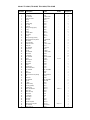
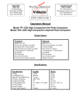
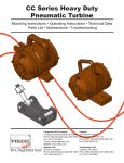
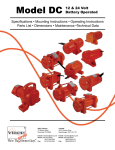
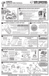
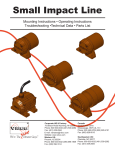
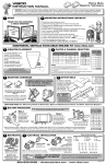
Head Office
Vibco, Inc.
75 Stilson Road
Wyomomg, RI 02898
TEL. 800-633-0032
FAX. 401-539-2584
Canadian Branch
Vibco Canada
2215 Dunwin Drive
Mississauga, Ontario L5L1X1
TEL. 905-828-4191
FAX. 905-828-5015
WWW.VIBCO.COM
Operators Manual
Model TP-1830 High Compaction Dirt Plate Compactor
Model TPA-1830 High Compaction Asphalt Plate Compactor
Engine Specs
Standard
Optional
Honda GX-160
Four cycle, gasoline, air cooled
Overhead valve, slant cylinder
Dual element heavy-duty air cleaner
5.5 Horsepower / 4.1 Kilowatts
3250 RPM
Rewind starter
Low oil alert system
Transistorized magneto ignition
Robin EY-20
Four cycle, gasoline, air cooled
Vertical cylinder
Heavy-duty air cleaner
5.0 Horsepower / 3.7 Kilowatts
3250 RPM
Rewind starter
Low oil alert system
Magneto ignition
Specifications
Specification
English
Metric
Weight
Centrifugal Force
Specific Centrifugal Force
Vibration Frequency
Compaction Depth
Contact Dimensions
Overall Width
Overall Length
Water Tank Capacity
160 lbs
3000 lbs
11.8 psi
5200 VPM
12”
17” width x 15” length
18”
21”
5 Quarts
73 kg
13.3 kN
81 kPa
87 hz
30 cm
43 cm x 38 cm
46 cm
53 cm
4.7 Liters
Introduction
Vibco plate type compactors are used for compacting loose layers of soil
or asphalt into load bearing surfaces. The vibration aligns the particles in the
material being compacted in order to achieve maximum density, thus eliminating
hollow spaces or cavities. They are successfully used for sandy, granular and
partially cohesive materials, as well as for asphalt finishing. The main
components of the compactors are; the base plate, vibratory element, engine
plate, steering handle and a water tank on asphalt models. The vibrational force
and forward motion of these machines is induced by rotation of an eccentrically
weighted shaft. The water tank on asphalt models wets the plate and pavement
surfaces appropriately to avoid the adhesion, which can occur with the asphalt
surface.
Serial Number Location
Engine
When ordering replacement parts from the engine distributor, state the
model, specification and serial number. Model and spec. numbers for both
engines are located on the flywheel cover. Honda serial numbers are found on
the front of the crankcase housing and the Robin serial numbers are located on
the base of the engine.
Compactor
The Vibco model and serial numbers are mounted on the front of the
engine plate. Furnish both numbers when corresponding with your authorized
dealer.
Maintenance
Keep your machine clean!
Every 10 hours or daily
1. Periodically check bolts and nuts for tightness, especially in the period
following initial operation.
2. Check engine oil daily.
3. Clear air filter periodically
4. Check and tighten element clamp screws with a torque wrench for 38-40
ft-lbs.
Every 50 hours or weekly
1. Check belt tension.
2. Change engine oil.
3. Check and tighten all nuts and bolts.
4. If water flow through the sprinkler pipe on asphalt units fails, clear pipe
using carburetor cleaner.
5. Check vibrator element seal for leaks.
Operating Notes
♦ Before starting the machine, READ the engine-operating manual
CAREFULLY.
♦ Remember to check the engine oil.
♦ Make sure the belt guard is securely bolted in place.
♦ The vibratory element is filled with 3 fluid ounces of SAE 90 EP gear
lubricant, and is sealed at the factory. Note! Do not overfill the element
if servicing, this can damage the unit extensively and may void the
warranty.
♦ Unlock the handle by removing the pin and lowering the handle to the
desired position. Reinsert the pin and the machine is ready to start.
♦ After warm up, move the control lever to full throttle position. The
motor should run at 3250 RPM maximum. The clutch will automatically
engage at approximately 1850 RPM, and vibration will begin. The unit
will now begin to pull itself forward.
♦ Let compactor move on its own power, and guide it by the handle.
Uneven or sloping terrain may cause the machine to slide sideways.
The operator must then steer toward the rise thus causing the
compactor to travel at an angle.
♦ Do not add fuel while the engine is running. Stop the engine, and if
possible, allow a cooling period to prevent spilled fuel from igniting on
contact with hot engine parts.
♦ Before making any adjustments, disconnect the spark plug cable to
prevent unintentional starting.
♦ Make sure that the belt guard is securely bolted in place.
♦ REMEMBER a careful operator is always the best insurance against
accidents.
Vibco, Inc. reserves the right to change and improve any parts or specifications
without notice, and without incurring any obligation relating to such change.
50
12
49
11
15
10 9 8
48 27
24
7
43
5
44
27
4
28
7
2
1
11
43
26
27
13
14
16
12
P.O. Box 8
Wyoming, RI 02898
Phone: 401-539-2392
800-465-9709
401-539-2548
FAX:
VIBCO, INC.
51
26
6
58
52
3
Model: TP-1830, TPA-1830
57
55
53
54
In Canada:
46
23
38
18
2
24
25
17
22
26
27
2215 Dunwin Drive
Mississauga, Ont. L5L 1X1
905-828-4191
800-465-9709
FAX: 905-828-5015 28
56
47
45
21
20
19
29
27
32
30 31
36
27
35
26
26
33
59
34
37
38
39
26
40
41
27 42
Model: TP-1830H, TP-1830R, TPA-1830H, TPA-1830R
Item
Number
1
2
3
4
5
6
7
8
9
10
11
12
13
14
15
16
17
18
19
20
21
22
23
24
25
26
27
28
29
30
31
32
33
34
35
36
37
38
39
40
41
42
43
44
45
46
47
48
49
50
51
52
53
54
55
56
57
58
59
Part
Description
Honda
Part Number
Robin
Baseplate
Lock Washer
Hex Head Bolt
Socket Set Screw
Bushing
Sheave
Retaining Ring
C.R. Seal
Oil Shield
Bearing Housing (Open)
O-Ring
Bearing
Eccentric Shaft
Key (Shaft)
Housing
Bearing Housing (Closed)
Flat Socket Head Cap Screw
Star Washer
Shock Absorber
Socket Set Screw
Sliding Flat
Hex Head Bolt
Engine Plate
Hex Nut
Hex Head Bolt
Flat Washer
Lock Washer
Hex Head Bolt
Engine
Clutch Spacer
Key (Clutch)
Flat Washer
Handle
Shoulder Bolt
Belt Guard Bracket
Hex Head Bolt
Clutch
Flat Washer
Flat Socket Head Cap Screw]
Belt
Belt Guard
Hex Head Bolt
Hex Nut
0
90 Barb
Sprinkler Clamp
Pipe Plug (Plastic)
Sprinkler Pipe
Water Tank Bracket
Water Tank
Water Tank Cap
Flat Washer
Lock Washer
Dixon Clamp
Flow Valve
Hose (2ft.)
Element Complete
Water System Complete
Hex Head Bolt
Handle Lock Pin
201059
1/2LW
1/2-20X2-3/4HH
1/4-20X1/2SS
201016
201015-1
201022
201025
201143
122020
122026
201023
122019-2
201017
120224-2
122021
1/2-13X5/8FSH
1/2SW
201028
1/2-13X1-1/2SS
201034
1/2-13X1HH
201032
3/8-16HN
3/8-16X2-1/2HH
5/16FW
5/16LW
5/16-18X1-3/4HH
GX-160
18VR043
201084
9/16FW
201100
201140
201142
M8X1.25X16MM
201095
1/2FW
5/16-24X3/4FSH
201128
201098
M8X1.25X25MM
5/16-18HN
122030
201129
122041
122103-2
122051-2
201204
201205
3/8FW
3/8LW
133
201134
122094
122018-2
201014-2
5/16-18X1HH
201033
EY-20
122051-1
201014-1
-
Number
Required
1
4
2
1
1
1
2
1
1
1
2
2
1
1
1
1
4
4
4
2
2
2
1
4
2
14
15
6
1
1
1
2
1
2
1
1
1
3
1
1
1
2
2
1
2
1
1
1
1
1
2
2
4
1
1
1
1
4
1