1
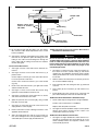
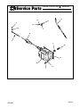
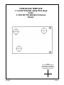
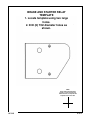
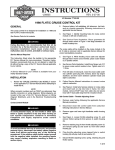
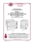
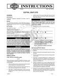
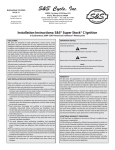
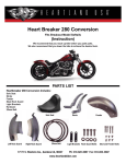
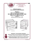
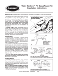
INSTRUCTIONS
-J01348
®
REV. 4-23-99
Kit Numbers 77173-99, 77174-99, 77175-99, 77208-99, 77209-99, 77210-99, 77211-99
FLHR CRUISE CONTROL KITS
General
The kits covered by this Instruction Sheet fit the following
models:
Kit Number ........Model Fitment
77173-99 ............1996 FLHR
77174-99 ............1996 FLHRI
77175-99 ............1994-1995 FLHR
77208-99 ............1997 FLHR
77209-99 ............1998-1999 FLHR
77210-99 ............1997 FLHRI
77211-99 ............1998-1999 FLHRCI
1WARNING
To avoid accidental start-up of motorcycle, and possible
personal injury, disconnect the battery cables (negative
cable first) before performing any of the following procedures. If the battery should contact ground with the negative cable installed, the resulting sparks may cause a battery explosion resulting in death or serious personal
injury.
1.
See Service Parts page for kit contents.
1WARNING
Harley-Davidson, Inc. recommends that this kit be
installed by a Harley-Davidson authorized dealer.
Improper installation could cause cruise control
malfunction, loss of control, and could result in death or
serious injury.
Service Manual Required
This Instruction Sheet refers the installer to the appropriate
FLT Service Manual for many procedures. Harley-Davidson
recommends that you do not attempt to install this kit without
having a copy of the Service Manual for your vehicle.
NOTE
A Service Manual for your vehicle is available from your
Harley-Davidson Dealer.
For 1997-1999 Models
2.
See Figures 1. and 2. Identify mounting holes for cruise
control module on left side of battery box.
3.
See Service Parts illustration. Place grommets (6)
through holes shown in Figure 1 or Figure 2 with large
diameters on inside of battery box.
NOTE
The cruise cable will be installed on the cruise module in the
kit. If cable is removed, refer to applicable Service Manual for
correct reinstallation procedure.
4.
See Figure 3. While feeding cruise cable and adjuster
through hole in frame cross member, place cruise module
in position shown.
5.
See Service Parts. Install three flange nuts to secure
cruise module to box. Tighten nuts to 9-11 ft-lbs. Proceed
to step 9 on page 1.
INSTALLATION
Review the “CRUISE CONTROL-Ultra MODELS” section in
the Service Manual before attempting to install this kit.
NOTE
When connector numbers such as “[22A]” are referenced, they
identify connectors on wiring diagrams. Wiring diagrams are
located at the rear of the FLT Service Manual, on the wiring
diagram wallcharts, and in the Electrical Trouble Shooting
Manual.
Cruise Control Module
For 1994-1996 Models
1.
Drill cruise module mounting bracket using the template
provided in this instruction sheet.
2.
See Service Parts illustration. Remove the three studs
from cruise module mounting holes and discard studs.
Install module mounting bracket (21) onto module with
grommets (6) and truss head screws (34).
3.
Remove the fuse block, starter relay, and brake relay.
4.
Remove the ignition switch harness connectors from
mounting bracket under left sidecover, then remove
mounting bracket and discard.
5.
Drill two holes in battery tray bracket using the template
provided in this instruction sheet.
6.
See Figure 3. Place cruise module in position shown. The
mounting bracket installed in step 2 has the same hole
pattern as the old style module shown in Figure 6.
7.
See Service Parts illustration. Secure module mounting
bracket in place using washers (15) and screws (7) from
kit. Tighten screws to 6 ft-lbs.
1WARNING
To avoid personal injury, do not smoke or allow open
flame or sparks anywhere in the area when working on
fuel system components. Gasoline is extremely flammable and highly explosive under certain conditions, and
may result in death or serious injury.
Remove battery, left saddlebag, left sidecover, fuel tank,
and air cleaner assembly following instructions in applicable Service Manual.
1 of 15
F1419
F1419
Cruise module
mounting holes
Cruise module
mounting holes
Left side of
battery box
Left side of
battery box
Figure 2
Cruise Module Mounting Holes for
1997 FLHR
Figure 1
Cruise Module Mounting Holes for
1997 FLHRI
1998-1999 FLHR/C/I
i00742
®
2
4
1.
2.
3.
4.
3
1
Cruise module (old style shown)
Cruise cable
Connector latch
Cruise connector [17B]
Figure 3. Mounting Cruise Module
i01415
Instrument Harness
Connector [20]
Ignition
Switch
Connector
[33]
Brake
Relay
Fuse Block
Starter
Relay
Figure 4.
-J01348
2 of 15
8.
Relocate the fuse block, starter relay, brake relay, instrument and ignition switch harness as shown in Figure 4.
9.
Connect cruise cable to cruise module and route cable
under rear cylinder spark plug wire; forward, above top
engine stabilizer; and right to carburetor. Follow instructions in applicable Service Manual when connecting
cruise cable to cruise module and carburetor.
NOTE
Saddlebag, sidecover, and air cleaner assembly should not be
reinstalled at this time.
10. From left side of motorcycle, route the cruise cable under
rear cylinder spark plug wire; forward, above top engine
stabilizer; and then down between cylinder heads and
right to induction module.
11. Follow Service Manual instructions to connect cruise
cable to induction module.
12. See Figure 5. Install wire harness retainer on cruise cable
and insert barb on clip into hole in frame. On Calif. models, remove EVAP hose from cable clip and secure hose
with T-stud cable strap from kit in location shown.
5.
Remove retaining ring (4) from throttle adjusting screw (1)
and remove spring (5) and screw (1) from lower switch
housing (3).
6.
Plug throttle adjusting screw tapped hole in switch housing (3) with pop rivet (6) and washer (7).
7.
Discard throttle adjusting screw, spring, retaining ring and
friction spring.
8.
Remove idle control cable brass ferrule from notch in
throttle grip. Retain brass ferrule for use later.
9.
Follow instructions in Section 2 of applicable Service
Manual to remove stock idle cable.
10. Follow instructions in Section 8, CRUISE CONTROLTHROTTLE CABLES, of applicable Service Manual and
install the new idle control cable from kit.
i00946
Idle Control Cable - Throttle Adjusting Screw
1.
Remove headlamp following the applicable Service
Manual procedures.
2.
Disconnect stock idle control cable from carburetor following instructions in Service Manual.
3.
Remove upper and lower right handlebar switch housing
screws.
NEW
OLD
4.
See Figure 7. Loosen throttle adjusting screw (1), and
remove friction spring (2) from groove in switch housing
(3).
Figure 6. Cruise Control Modules
i00295
i00998
2
T-stud for attaching EVAP
hose on Calif. models
4
3
7
5
Rear cylinder head
Cable clip
Figure 5. Attaching Cruise Cable Adjuster
(Left Side View)
-J01348
1
1. Throttle adjust. screw
2. Friction spring
3. Lower right switch
housing
4.
5.
6.
7.
6
Retaining ring
Spring
Pop rivet
Washer
Figure 7. Throttle Adjusting Screw and Tapped Hole
3 of 15
i00303
Cruise control harness
Throttle cable
Roll-off switch wires
inboard of throttle &
idle cables
Coiled tubing
Idle cable
Roll-off switch
wire connections
Figure 8. Throttle / Idle Cable and Roll-off Switch Configuration
11. Do not adjust throttle and idle cables now. The throttle,
idle, and cruise cables will be adjusted after cruise control
harness installation.
12. See Figure 8. Install the coiled tubing on the throttle cable
from front to rear. Open the split in the tubing, place the
tubing on the cable and feed tubing back through the
frame clamp until the tubing end contacts the induction
module cable guide.
Cruise Control Wire Harness
1.
See Figure 9. Cruise control wire harness electrical connections.
2.
See Figure 10. Place cruise control wire harness (1) in
position shown.
Connect 4-place connector (3) cruise control wire harness
to accessory harness under seat.
Connect cruise control wire harness (1) to cruise module
(2) [17A].
3.
Route cruise control wire harness (1) to right side of frame
and then towards the front.
4.
See Figure 11. Place cruise control wire harness along
right side of frame backbone forward of seat.
5.
See Figure 8. Position the roll-off switch wires as shown,
and connect the terminals to the switch.
6.
Splice into pink wire from connector [8A], using a sealed
butt splice connector (23).
7.
See Figure 9. Insert pink wire from cruise harness into
empty position in connector [8A].
8.
Remove instrument console following instructions in the
applicable Service Manual.
9.
Splice the white/green wire from the cruise control harness to the white/green wire of the speedometer using the
sealed butt splice connector (23) provided in the kit.
-J01348
Set/Resume Switch and Cruise Control Wire Harness
Placement Into Handlebar Clamp
1CAUTION
Do not disconnect or remove the switch housing
assembly without first placing a 5/32 inch thick cardboard
insert or cable strap eyelet between the brake lever and
lever bracket. Housing removal without an insert may
result in damage to the rubber boot and plunger of the
front brake light switch.
1.
See Figure 17. Remove the two screws and washers (1)
that secure the master cylinder clamp (2) and master
cylinder (3) to the handlebar and remove master cylinder
clamp (2). Discard the two screws and retain the washers
for use later.
2.
Remove from the kit and insert the escutcheon (4) into the
set / resume handlebar clamp (5).
3.
Insert switch (6) with side having two tabs (7) positioned
as shown.
4.
Press switch (6) into escutcheon (4) until it latches into
position.
5.
Install speednut (8), place actuator (9) on switch rod and
press until actuator pins enter holes in switch tabs (10).
Set/Resume Switch Attachment to Handlebar Clamp
1.
Cut the cable strap securing harnesses to right handlebar.
Position cruise control harness on handlebar.
Replace cable strap with one from kit.
2.
See Figure 16. Attach handlebar clamp to master cylinder
with the stock washers and two 1/4-20 x 1-5/8 in. hex
socket button head screws from kit.
Set/Resume Switch Electrical Connections
1.
See Figure 18. Begin Set/Resume switch electrical connections by inserting the wires and terminals (5) on the
switch assembly harness into respective cavities of wire
seal assembly (2) from kit.
4 of 15
i00722b.eps
J01348
Throttle
Roll Off Switch
(on Idle Control
Cable)
Cruise Control
Module
a
r/gn
b
be/bk
c
w/be
d
v/y
e
bk
f
o/v
g
r/be
h
To
Indicator Lamps
(on handlebar
clamp)
o/v
bk
v/y
To Left Ground
Stud
(under seat)
gn/r
o/v
r/gn
bk
pk
j
gn/r
k
w/gn
w/gn
To P&A Accessory
Connector [4A]
(under seat)
pk
o/v
r/be
r/gn
bk
o/v
be/bk
w/be
1 2 3 4
To Connector
[8A] Pin 3
(under right side
cover)
5 of 15
Figure 9. Electrical Connections
4
3
2
1
Splice to W/Grn
Speedometer wire
(under console)
c
b
a
To
Handlebar
Controls
2.
Insert the locking pin (1) with arrow (3) on pin (1) pointing
toward the latch cover(4).
NOTE
If locking pin (1) does not “snap” into position, make sure all
pin terminals (5) are fully inserted into the wire seal (2).
3.
Carefully center punch on centers of holes to be drilled.
4.
Drill 1/16 in. pilot holes followed by 5/32 in. finished holes.
5.
Slip lamps into drilled holes (red lamp on left, green lamp
on right).
3.
Install the locking pin (1) attachment clip in the dovetail (7)
of the kit supplied pin housing (8).
1CAUTION
4.
Connect the two connector halves and attach the attachment clip to the T-stud on the inner side of the outer fairing bracket.
Do not press on lamp when installing speednut. Press
only on black housing or lamp may be damaged.
Cruise Control ON/OFF Switch
1.
The accessory switch on the right hand side of the nacelle
is used as the cruise control ON/OFF switch.
J-Clamp and Throttle Cable
1.
See Figure 15. Using the sharp edge of a knife, carefully
pull out the plastic plug in forward area of frame.
2.
Install well nut from kit in hole. Install flat washer and Jclamp on screw. Start screw into well nut. With the loop of
the clamp orientated at the top, tighten the clamp screw
until snug.
3.
Position the throttle control and idle control cables within
the J-clamp. Pinch or press ends of clamp closed to contain cables.
6.
Place speednuts on indicator lamps.
7.
Assemble wire leads into four place connector as shown
in Figure. 12.
8.
Connect pin connector to wiring harness.
9.
Reinstall handlebar clamps as described in the
appropriate Service Manual.
Cable Straps
1.
See Figures 10, 11, and 13. Install cable straps as shown.
2.
See Figure 14. Attach cruise cable to frame by installing
T-stud clip with cable strap (1) and place the T-stud clip
on T-stud.
3.
Check that all wires and harnesses are located away from
hot or moving parts.
Drilling Handlebar Clamp
Adjust Throttle, Idle, and Cruise Control Wire Harness
1.
Remove handlebar clamp per instructions in the applicable Service Manual.
1.
Refer to the “CRUISE CONTROL - THROTTLE CABLES”
section in Section 8 of the applicable Service Manual and
adjust the throttle, idle control cable and cruise cables.
2.
Using drill template provided at the end of this instruction
sheet, position on handlebar clamp making sure to align
outer edges of template with outer edges of handlebar
clamp. Use tape to hold in place.
2.
Reinstall saddlebag, right side cover, and air cleaner
assembly.
3.
Adjust cruise cable last in accordance with the procedure
in the applicable Service Manual.
i00299
NOTE
Numbers in brackets are connector numbers used in wiring diagrams.
1. Cruise control wire harness
2. Cruise control wire harness
connection to cruise module [17A]
3. Cruise control wire harness
connection to main harness [6A]
4. Rear fender connector [7]
5. Cruise cable to carburetor
4
3
1
5
2
Figure 10. Cruise Control Wire Harness Connections at Cruise Module
-J01348
6 of 15
1
i00297
4
4
Arrow heads show cruise
cable routing.
3
2
1.
2.
3.
4.
Cruise control wire harness
Cruise disengage switch leads
Cable clamp
Cable straps
Figure 11. Attachment, Wire Harness to Frame
i01586.eps
3 Orange/Violet
4 Green/Red
DEUTSCH
1 Black
From Green Indicator Lamp
2 Red/Green
1 Black to Black
From Red Indicator Lamp
DEUTSCH
3 Red to Orange/Violet
4 Black to Green/Red
2 Red to Red/Green
Figure 12. Four Place Connector
FINAL CHECK AND TEST RIDE
1.
2.
Check that all connections have been made and that all
wiring is properly secured with cable straps.
Perform the “Switch Diagnostic Sequence”, in the applicable Service Manual, before installing fuel tank, outer fairing, left side cover, and left saddlebag.
1WARNING
Always connect the positive battery cable first. If the
positive cable should contact ground with the negative
cable installed, the resulting sparks may cause a battery
explosion resulting in personal injury.
3.
-J01348
To perform the tests reconnect battery, positive cable first.
7 of 15
1WARNING
To avoid accidental start-up of motorcycle, and possible
personal injury, disconnect the battery cables (negative
cable first) before performing any of the following procedures. If the battery should contact ground with the negative cable installed, the resulting sparks may cause a battery explosion resulting in death or serious personal
injury.
4611
Steering head
i00302
Frame backbone
Plastic plug
Cable
strap
Figure 15. Remove Plug From Frame
Roll-off
Switch
wires
6.
Connect battery, positive cable first.
7.
Install seat.
1WARNING
Figure 13. Roll-off Switch Wires
4200
2
3
After installing seat, pull upward on front of seat to be sure
it is locked in position. If seat is loose, it could result in
shifting during vehicle operation, loss of control of vehicle,
death or serious injury.
8.
Refer to cruise control section in Owner’s Manual for
cruise control operating instructions.
9.
Test ride motorcycle and verify cruise control is operating
properly.
1
1. Cable strap
2. T-stud
3. Cruise cable adjuster
Figure 14. Cruise Cable Attachment to Frame
4.
After tests are completed disconnect battery, negative
cable first.
5.
Install fuel tank, left side cover, headlamp and left saddlebag.
1WARNING
Always connect the positive battery cable first. If the positive cable should contact ground with the negative cable
installed, the resulting sparks may cause a battery explosion resulting in death or serious injury.
-J01348
8 of 15
i00292
11
i00300
10
3
7
1
10
6
2
5
4
8
9
1.
2.
3.
4.
Screw and washer (2)
Master cylinder clamp
Master cylinder
Escutcheon
5.
6.
7.
8.
Handlebar clamp
Switch
Tabs (wire end of switch)
Speednut
9. Actuator
10. Tabs, actuator (2)
11. Harness
Figure 16. Installing Set / Resume Switch
i00722a
Handlebar Clamp
Stock Washers and
Hex Head Screws
from kit
Set / Resume
Switch
Figure 17. Set / Resume Switch Attachment
i00293
A
5
2
8
4
1
B
6
C
WIRE COLOR
CAVITY
White/blue
Blue/black
Orange/violet
A
B
C
7
1.
2.
3.
4.
Locking pin
Wire Seal
Arrow
Latch cover
3
5.
6.
7.
8.
Pin terminal
Socket side (for reference only)
Attachment clip dovetail
Pin housing
Figure 18. Set / Resume Switch Connections
-J01348
9 of 15
®
Service Parts
Part No. 77173-99 + others
Date 4/99
FLHR Cruise Control Kits
77127-93C
11
13
10
5
33
16
1
12
5
6
34
21
24
15
7
-J01348
10 of 15
Date 4/99
77175-99
77208-99
77209-99
77210-99
77211-99
FLHR Cruise Control Kits
77174-99
Service Parts
Part No. 77173-99 + others
77173-99
®
Description (Qty)
J-clamp
Part No.
10003
X
X
X
X
X
X
X
2
Cable straps (11), 15 inch, not shown
10039
X
X
X
X
X
X
X
3
Cable straps (3), 5 inches, not shown
10073
X
X
X
X
X
X
X
4
T-stud clip, not shown
10133
X
X
X
X
X
X
X
5
Retaining rings (2)
11193
X
X
X
X
---
X
---
6
Grommets (3)
11497
X
X
X
X
X
X
X
7
Hex capscrews (3), 1/4-20 x 5/8
3767B
X
X
X
---
---
---
---
8
Buttonhead screws (2), not shown
4033
X
X
X
X
X
X
X
9
Handlever clamp, not shown
45043-89
X
X
X
X
X
X
X
10
Well nut
5207
X
X
X
X
X
X
X
11
Idle control
56237-99
X
X
X
X
X
Item
1
56228-99
X
56236-99
12
X
Stepper cable
56405-98
X
X
X
56372-97
X
56372-98
X
X
X
13
Washer, 5/8 x 13/64 x 3/64
6047
X
X
X
X
X
X
X
14
Conduit, 1/4 in. ID x 12 inches, not shown
63574-94
X
X
X
X
X
X
X
15
Washer, 1/4 x 5/8 x 1/16
6703
X
X
X
---
---
---
---
16
Washer, #10 x 1/2 x 3/64
6716
X
X
X
X
---
X
---
17
Washer, #6 x 3/8 x 3/64, not shown
6717
X
X
X
X
X
X
X
18
Green indicator lamp assembly, not shown
68040-99
X
X
X
X
X
X
X
19
Red indicator lamp assembly, not shown
68161-99
X
X
X
X
X
X
X
20
Cruise control harness, not shown
70141-99
X
X
X
X
X
X
X
21
Cruise module adapter bracket
70183-98
X
X
X
---
---
---
---
22
Conduit, .133 in. ID x 30 inches, not shown
70530-89
X
X
X
X
X
X
X
23
Sealed butt splice, not shown (2)
70586-93
X
X
X
X
X
X
X
24
Cruise module
70989-98
X
X
X
X
X
X
X
25
Pin housing, 3-place, not shown
72103-94BK
X
X
X
X
X
X
X
26
Pin housing, 4-place, not shown
72104-94BK
X
X
X
X
X
X
X
-J01348
11 of 15
®
Service Parts
Part No. 77173-99 + others
Date 4/99
FLHR Cruise Control Kits
Description (Qty)
Part No.
77173-99
77174-99
77175-99
77208-99
77209-99
77210-99
77211-99
spxxxxx
27
Secondary lock, 3-place, not shown
72143-94
X
X
X
X
X
X
X
28
Secondary lock, 4-place, not shown
72144-94
X
X
X
X
X
X
X
29
Flange locknut, not shown
7716
X
X
X
---
---
---
---
30
Set/resume switch, not shown
77101-90B
X
X
X
X
X
X
X
31
Pushnuts (2), not shown
7905
X
X
X
X
X
X
X
32
Blind rivet, not shown
8625
X
X
X
X
X
X
X
33
Machine truss screw
933
X
X
X
X
X
X
X
34
Truss screw, M6 x 1
958
X
X
X
---
---
---
---
35
Wire harness retainer, not shown
56073-83
---
---
---
X
X
X
X
36
Wire harness retainer, not shown
70345-84
---
---
---
X
X
X
X
37
Flanged locknuts (3), not shown
7499
---
---
---
X
X
2
X
38
Nut, nylon insert, 10-24 (4), not shown
7624
X
X
X
----
---
---
---
Item
-J01348
12 of 15
Drill Templates
i01416
HANDLEBAR CLAMP TEMPLATE
NOTE
These marks should measure
exactly 1 inch in each direction.
Please measure to verify that this
template is the correct size.
J01348
13 of 15
i01417
FUSE BLOCK TEMPLATE
1. Locate Template using three large
holes.
2. Drill (2) 7/32 diameter holes as
shown.
NOTE
These marks should measure
exactly 1 inch in each direction.
Please measure to verify that this
template is the correct size.
J01348
14 of 15
i01418
BRAKE AND STARTER RELAY
TEMPLATE
1. Locate template using two large
holes.
2. Drill (2) 7/32 diameter holes as
shown.
NOTE
These marks should measure
exactly 1 inch in each direction.
Please measure to verify that this
template is the correct size.
J01348
15 of 15