1
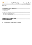
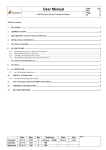
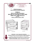
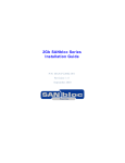
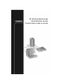
2U STORAGE ENCLOSURE
QUICK INSTALL GUIDE
FS4100, FS4500, SC4100, AND FC4100
Kit Contents
■
Adaptec Storage Enclosure (FS4100, FS4500, SC4100, or FC4100)
■
CD, including software, drivers, and documentation
■
Two power cables
Note: Mounting rails for rack installations are sold separately.
See your Adaptec reseller for purchase information.
Installation Checklist
❏ Read and follow the safety tips. See page 2.
❏ Install the enclosure in an equipment rack or tower assembly
(optional.) See page 2.
❏ Install the drive carriers. See page 6.
❏ Set the drive slot and enclosure IDs. See page 7.
❏ Connect the I/O cables. See page 7.
❏ Connect the AC power cords to the APC modules. See page 11.
❏ Follow the instructions in Next Steps on page 11.
1
Safety Tips
!
Caution: A fully loaded enclosure is heavy. Reduce the weight
of the enclosure by removing the drive carriers before
installing the enclosure in the rack or tower. (You can also
remove the two APCs to further reduce the weight, if
required. See the Adaptec Storage Enclosure Installation and
User’s Guide on the CD for instructions.)
!
Caution: To prevent personal injury, have someone assist you
during rack installation.
!
Caution: If you are installing your enclosure in a rack, prevent
personal injury and equipment damage by following the rack
manufacturer’s safety instructions. Install your enclosure only
in a rack that has been properly secured in an area with
suitable environmental conditions.
Step 1: Installing into a Rack or Tower
(optional)
Note: Mounting rails for rack installation are sold separately.
To purchase a rail kit, see your Adaptec reseller.
Required tools:
■
Phillips-head screwdriver
■
Wrench for tightening nuts (if your rack does not have threaded
holes)
If you are not installing your Storage Enclosure into a rack or
tower, skip to Step 2: Installing the Drive Carriers on page 6.
■
To install your Storage Enclosure into an rack, see page 3.
■
To install your Storage Enclosure into a tower assembly, see
page 5.
2
Installing into an Equipment Rack
Begin the installation by removing the components from the
packaging and placing them on an antistatic surface until you need
them.
Ensure that you have all these rail kit components:
■
Front rails (1 left, 1 right)
■
Rear rails, two different sizes (2 left, 2 right)
■
Two sizes of screws (10 large, 4 small)
■
Two types of nuts (10 of each)
To install your Storage Enclosure in an equipment rack:
1 Secure the front rails to the front supports of the rack, using the
supplied screws, as shown below.
Note: Use either the speednuts or cagenuts provided if
your rack does not have threaded holes.
2 Check the length between the front and rear supports of your
equipment rack and determine which set of rear rails to use, the
long or the short.
3
3 Secure the rear rails you selected to the rear supports of the
equipment rack, using the supplied screws, as shown in the
Figure in Step 1 on page 3.
4 Secure the front rails to the rear rails, as shown below.
5 Tighten all the screws before continuing.
6 With assistance from a second person, lift the Storage Enclosure
and slide the rear of the enclosure onto the rails. Slide the
enclosure all the way back until it rests completely on the rails,
as shown in the Figure below.
You can choose to have someone continue to support the
enclosure until it is secured in the rack, although this extra
support is not required.
4
7 Secure the front of the enclosure with one screw on each side, as
shown in the next Figure.
One screw per side
The equipment rack installation is complete. Continue with Step 2:
Installing the Drive Carriers on page 6.
Installing into a Tower Assembly
A tower assembly is also referred to as a deskside assembly or
pedestal.
!
Caution: Do not modify the tower assembly. The feet are
designed to keep the tower from tipping over. Do not remove
the acoustic foam inside the tower skin assembly.
1 If the Storage Enclosure is already set up and running, shut
down the enclosure and remove all cables and power cords. You
can remove all the drive carriers and both APCs to reduce the
weight of the enclosure, if required.
If the enclosure is in an equipment rack,
remove the two screws holding it in place at
the front, then slide the enclosure out of the
rack. Remove both the right and left rack
mount ear plastic covers (shown at right), as
they are no longer needed. (They can be
removed by pressing on the plastic inserts
from the backside of the rack mount ear or
pried off with a screwdriver).
2 Unpack the tower and inspect it for shipping damage. Do not
install the enclosure into a damaged or bent tower assembly.
5
3 Remove the tower’s front bezel, as shown below, saving the
screws for use in Step 5.
Step 3
Step 4
4 Turn the enclosure 90° so that the right hand rack mount ear
and LEDs are on top, then slide the Storage Enclosure into the
tower skin, as shown above.
5 Replace the front bezel, using the screws removed in Step 3.
6 Install the tower labels at the top and bottom of the tower. Align
the holes in the top label with the LEDs on the enclosure.
7 Replace the drive carriers and APCs, if necessary.
The tower assembly installation is complete. Continue with Step 2:
Installing the Drive Carriers, below.
Step 2: Installing the Drive Carriers
These instructions assume that the drive carriers have already been
attached to your disk drives.
!
Caution: Acclimate new disk drives to room temperature
before you install them and power up the Storage Enclosure.
To install the drive carriers into the Storage Enclosure:
1 Hold the drive carrier with the LEDs on the left side (at the
bottom for tower-mounted systems) and select an open disk
drive slot.
Note: It is easiest to install the drive carriers from left to
right on the Storage Enclosure.
6
2 With the cam lever of the drive slot fully open, slide the carrier
into the slot until the lever starts to close.
3 Push the cam lever until it engages the latch on the left side of
the carrier assembly and clicks into place.
4 Repeat for all drive carriers.
Note: Either a drive carrier or a carrier blank must be installed
in all the slots of the enclosure to maintain proper airflow and
cooling.
When all drive carriers are installed, continue with Step 5:
Connecting Power Cords to the APC Modules.
Step 3: Setting the Drive Slot and Enclosure IDs
Each drive slot has a unique ID assigned to it. The IDs are assigned
by a combination of enclosure ID and slot number.
Enclosure IDs must be assigned before the unit is powered on. You
set the enclosure ID to any number on the ID switch of the ES
module. The ES module is located on the rear of the Storage
Enclosure, between the two APC modules.
Slot numbers are preassigned.
Note: The enclosure ID numbers available on the ID switch
vary by enclosure model, and are not available on the SC4100.
For detailed information about your specific Storage
Enclosure, refer to the Adaptec 2U Storage Enclosure Installation
and User’s Guide on the CD.
Step 4: Connecting the I/O Cables
To connect the I/O cables to your Storage Enclosure, follow the
instructions provided for your specific Storage Enclosure interface:
■
For a SATA interface (Adaptec FS4100 or FS4500), see page 8.
■
For an FC interface (Adaptec FC4100), see page 9.
■
For an Ultra320 SCSI interface (Adaptec SC4100), see page 10.
7
Connecting SATA Cables
The FS4100 and FS4500 Storage Enclosures have removable Small
Form-factor Pluggable (SFP) connectors that support copper or
optical cables. Ensure that you have the appropriate SFP installed
for your cables. See the Adaptec 2U Storage Enclosure Installation and
User’s Guide on the CD for more cabling information and for daisychaining instructions.
JBOD Configuration (FS4100)
FS4100 SATA I/O Module
HOST 1
EXP 1
HOST BUS ADAPTER
HOST 2
EXP 2
HOST BUS ADAPTER
Daisy-chain
Daisy-chain
to next
to next
FS4100
FS4100
RAID Configuration (FS4500)
FS4500 SATA I/O Module
HOST 1
HOST 2
HOST BUS ADAPTER
ENET
EXP
Ethernet
Port
Daisy-chain
HOST BUS ADAPTER
to
FS4100
8
Connecting FC Cables
The FC4100 Storage Enclosure has removable Small Form-factor
Pluggable (SFP) connectors that support copper or optical cables.
Ensure that you have the appropriate SFP installed for your cables.
See the Adaptec 2U Storage Enclosure Installation and User’s Guide on
the CD for more cabling information and for daisy-chaining
instructions.
Single Loop Configuration
FC4100 FC I/O Module
OUTPUT
Daisy-chain
INPUT
HOST BUS ADAPTER
to next
FC4100
Dual Loop Configuration
FC4100 FC I/O Module
FC4100 FC I/O Module
OUTPUT
Daisy-chain
INPUT
OUTPUT
Daisy-chain
HOST BUS ADAPTER
to next
to next
FC4100
FC4100
9
INPUT
HOST BUS ADAPTER
Connecting Ultra320 SCSI Cables
See the Adaptec 2U Storage Enclosure Installation and User’s Guide on
the CD for supported cable lengths and additional cabling
information.
!
Caution: Use only Ultra320 certified cables. Ultra160 certified
cables are not supported by the Adaptec SC4100 Storage
Enclosure.
Single Bus Configuration
SC4100 SCSI I/O Module
HOST BUS ADAPTER
Dual Bus Configuration
SC4100 SCSI I/O Module
HOST BUS ADAPTER
HOST BUS ADAPTER
10
Step 5: Connecting Power Cords to the APC
Modules.
Connect one of the supplied power cords to each of the APC
modules and to a grounded power outlet.
!
Caution: Always use a regulating uninterruptible power
supply (UPS) to protect your Storage Enclosure.
Next Steps
See the Adaptec 2U Storage Enclosure Installation and User’s Guide on
the CD for instructions on how to complete these final installation
and set-up tasks for your specific Storage Enclosure model:
■
Powering on your system and configuring your enclosure.
■
Installing the storage management software:
■
The FS4100, FC4100, and SC4100 Storage Enclosures are
managed with Adaptec Storage Examiner software. (Refer to
the Adaptec Storage Examiner User’s Guide on the CD included
with your kit for detailed usage instructions.)
■
The FS4500 Storage Enclosure is managed with Spheras
RAIDWatch software. (Refer to the Spheras RAIDWatch
User’s Guide on the CD included with your kit for detailed
usage instructions.)
11
R
Adaptec, Inc.
691 South Milpitas Boulevard
Milpitas, CA 95035 USA
©2004 Adaptec, Inc.
All rights reserved. Adaptec and the Adaptec logo
are trademarks of Adaptec, Inc. which may be
registered in some jurisdictions.
Part Number: MAN-4000-QUIK, Rev. 13, LB 07/04