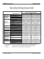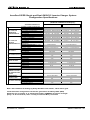
1
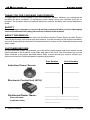
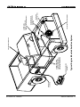
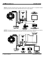
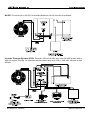
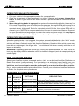
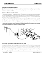
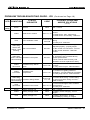
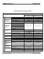
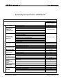
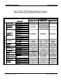
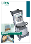
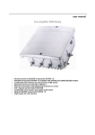
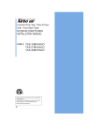
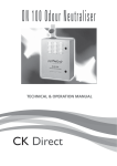
AURAGEN® INDUCTION POWER SOURCE
OWNER’S MANUAL
M1120221-3
Date: 090630
Typical Under-Hood Installation
Power Take Off (PTO) Driven
Hydraulically Driven
“The AuraGen”
The AuraGen® Induction Power Source provides several distinct advantages over portable generator systems. These include:
Mobile Power:
With the AuraGen system you have electrical power with you wherever you go with your vehicle.
There is also no output power penalty for changes in altitude or ambient temperature.
Load-Following:
Unlike typical portable generator sets which run at a constant engine speed (usually 3,600 RPM),
the AuraGen systems produces clean, pure sine wave, 60 or 50 Hz electrical power at any engine RPM. The output voltage and frequency will not fluctuate due to momentary or sustained
changes in engine speed.
Use of Automotive Engine:
Automobile engines are more efficient than small utility engines used in portable generators.
Modern electronic fuel injection systems continually optimize the engine performance and fuel
efficiency. The vehicle emission control system and muffler greatly reduce the amount of pollution and noise produced. The result is more automotive engine produced power, reduced noise,
and less pollution.
Maintenance Free:
Once installed, the AuraGen system is virtually maintenance free. Forget about the daily small
engine maintenance of the carburetor, spark plugs, fuel system and other routine problems
associated with traditional generators. Just have the AuraGen serpentine drive belt inspected
periodically (refer to supplied Service Manual).
T A B LE O F C O N TE N T S
THANK YOU FOR CHOOSING OUR PRODUCT ................................................... ............ 1
SAFETY ............................................................................................................................ 1
ABOUT THIS MANUAL ..................................................................................................... 1
CUSTOMER RECORD ....................................................................................................... 1
THE AURAGEN SYSTEMS ................................................................................................ 2
DIAGRAM OF TYPICAL AURAGEN VEHICLE INSTALLATION....................................... 4
DIAGRAMS OF SPECIFIC AURAGEN SYSTEMS.......................................................... 5
SAFETY PRECAUTIONS .................................................................................................. 7
GENERAL SAFETY PRECAUTIONS.............................................................................. 8
EXHAUST GASES......................................................................................................... 8
MOVING PARTS CAN CAUSE SEVERE PERSONAL INJURY OR DEATH..................... 8
ELECTRICAL SHOCK CAN CAUSE SEVERE PERSONAL INJURY OR DEATH............. 8
SPECIAL OPERATIONAL PRECAUTIONS ................................................................... 8
GENERAL OPERATING INSTRUCTIONS ......................................................................... 9
ALL-AC, AC/DC, ALL-DC SYSTEMS ............................................................................. 9
VEHICLES WITHOUT AUTO START......................................................................... 9
VEHICLES WITH AUTO START ............................................................................... 9
INVERTER/CHARGER SYSTEM................................................................................... 10
VEHICLE ENGINE RUNNING - CONTROL SWITCH OFF ........................................ 10
VEHICLE ENGINE RUNNING - CONTROL SWITCH ON........................................... 10
VEHICLE ENGINE OFF - CONTROL SWITCH OFF.................................................. 10
VEHICLE ENGINE OFF - CONTROL SWITCH ON.................................................... 10
TYPICAL ICS OPERATION....................................................................................... 10
OPERATION WHILE STATIONARY ................................................................................... 11
OPERATION WHILE DRIVING .......................................................................................... 11
HOW TO OBTAIN SERVICE ............................................................................................. 11
AURAGEN OPTIONAL EQUIPMENT ................................................................................ 11
REMOTE POWER STRIP.............................................................................................. 12
MANUAL TRANSFER SWITCH..................................................................................... 12
PUTTING YOUR AURAGEN SYSTEM TO USE ................................................................. 12
TYPICAL AURAGEN APPLICATIONS .............................................................................. 13
POWER CAPACITY .......................................................................................................... 13
WATTAGE REQUIREMENTS FOR TYPICAL APPLIANCES AND TOOLS ......................... 14
GENERAL INSPECTION ................................................................................................... 15
PROBLEM TROUBLESHOOTING ..................................................................................... 15
SYSTEM TROUBLESHOOTING GUIDE - ALL-AC, AC/DC AND ALL-DC ....................... 16
SYSTEM TROUBLESHOOTING GUIDE - INVERTER/CHARGER SYSTEM................... 18
AURAGEN SYSTEM SPECIFICATIONS ............................................................................ 20
ALL-AC ........................................................................................................................ 20
AC/DC ......................................................................................................................... 21
ALL-DC ........................................................................................................................ 22
6000X INVERTER/CHARGER ...................................................................................... 23
8500X INVERTER/CHARGER....................................................................................... 24
ALL-AC, ALL-DC, AC/DC/ENGINE-OFF INVERTER CHARGER SYSTEM...................... 25
ALL-AC, ALL-DC, AC/DC/ENGINE-OFF INVERTER CHARGER SYSTEM (Cont’d)........... 26
ALL-AC, ALL-DC, AC/DC/ENGINE-OFF INVERTER CHARGER SYSTEM (Cont’d)........... 27
AURAGEN/VIPER SINGLE & DUAL G8500YC INVERTER CHARGER SYSTEM........... 28
AURAGEN LIMITED WARRANTY ..................................................................................... 29
WARRANTY SERVICE OR REPAIR .................................................................................. 29
OWNER’S RESPONSIBILITY ....................................................................................... 29
NORMAL WEAR ........................................................................................................... 29
RETURN PROCEDURE ............................................................................................... 29
WARRANTY LIMITATIONS ........................................................................................... 30
DISCLAIMER OF IMPLIED WARRANTIES ................................................................... 30
M1120221-3, 090630
Owner’s Manual - i
THANK YOU FOR CHOOSING OUR PRODUCT
Congratulations on the purchase of your new AuraGen® system. Whether you purchased the
AuraGen for work, recreation, or emergency power needs, we’re very confident you’ll be impressed. The AuraGen family of products have been built for durability, with careful attention to
detail.
SAFETY
Do not attempt to operate or use your AuraGen system until after you have thoroughly
read and understand all safety precautions outlined in this manual.
ABOUT THIS MANUAL
This manual provides information about the AuraGen Induction Power Source models. Study it
carefully and comply with all warnings and cautions. Correct operation of this system and adherence to a simple general inspection schedule will result in longer unit life, better performance and
safer usage.
CUSTOMER RECORD
On your AuraGen system components, you will find the model number and serial number on the
labels adhered to the AuraGen cover plate and side of the ECU. We recommend you record
these numbers in the space provided below. Refer to them should you need to contact your
authorized AuraGen Distributor/dealer regarding this product.
Part Number
Serial Number
_______________
_______________
_______________
_______________
Induction Power Source
Electronic Control Unit (ECU)
Distributor/Dealer Name:
_________________________________
Phone Number:
_________________________________
Installation Date:
_______________
1 - Owner’s Manual
M1120221-3, 090630
THE AURAGEN SYSTEMS
(U.S. Patents No. 5,734,217 and 6,157,175)
The AuraGen System includes:
(Also see diagrams on pages 3-5)
•
•
•
•
•
Induction Power Source
Electronic Control Unit (ECU)
Control Panel
Idle Control Unit (some vehicles)
Mounting hardware and cables
(not shown)
Induction Power Source
Mechanical
Electronic
Idle Control
Electronic Control Unit
Standard
Inverter/Charger
Control Panel
Induction Power Source
Dual-Tandem Generator
16000 Watts
M1120221-3, 090630
Owner’s Manual - 2
Optional Equipment Available:
• Remote Power Strip
• Manual Transfer Switch
Remote Power Strip
Manual Transfer Switch
Ask your authorized AuraGen Distributor/dealer about the optional equipment.
3 - Owner’s Manual
M1120221-3, 090630
M1120221-3, 090630
Owner’s Manual - 4
RECEPTACLE
OUTLET BOX
Typical Engine Mounted AuraGen System
REMOTE POWER STRIP
(OPTIONAL)
CONTROL AND POWER
CABLES ROUTED UNDER
VEHICLE TO REAR-MOUNTED
ELECTRONIC CONTROL UNIT
ELECTRONIC CONTROL UNIT
GENERATOR
AURAGEN
MOBILE
AURAGEN INDUCTION
POWER
SOURCE
THROTTLE
CONTROL
IDLE CONTROL
(LOCATIONMAY
MAYVARY)
VARY)
(LOCATION
MOUNTING BRACKET
(ENGINE AND VEHICLE
SPECIFIC)
CONTROL UNIT
ON/OFF - STATUS LEDs
(USUALLY LOCATED UNDER DASH)
All-AC: Provides 120 VAC power to GFI outlets and/or 240 volt outlets. An optional remote
power strip with 120 VAC and/or 120/240 VAC service is also offered.
AC/DC: Provides 120 VAC power to GFI outlets and 14 or 28 VDC connected to the vehicle
batteries. An optional remote power strip with 120 VAC service is also offered.
5 - Owner’s Manual
M1120221-3, 090630
All-DC: Provides 14 or 28 VDC to auxiliary batteries. No AC service is available.
Inverter Charger System (ICS): Provides 120 or 240 VAC and 14 or 28 VDC power with or
without engine running. An optional remote power strip with 120 or 240 VAC service is also
offered.
M1120221-3, 090630
Owner’s Manual - 6
SAFETY PRECAUTIONS
! WARNINGS
Before operating the AuraGen®, read this Owner’s Manual and become thoroughly familiar with
the equipment and its features. Operation of the equipment can be achieved safely and efficiently when the unit is properly operated. Most equipment related accidents can be prevented
by following fundamental rules and precautions.
General Safety Precautions
• The AuraGen System must be installed and serviced only by AuraGen certified installers.
Consult your authorized AuraGen Distributor or Dealer or AuraGen Customer Service at (800)
909-AURA.
• DO NOT change pulley types or sizes as the Induction Power Source could exceed its 12,000
RPM limit resulting in possible component and/or system failure.
• DO NOT open or dismantle the AuraGen Induction Power Source, the Electronic Control Unit
(ECU), or any other components of the AuraGen system.
• DO NOT adjust anything on your AuraGen; see the local authorized AuraGen Distributor or
Dealer for this purpose.
• The ECU and Induction Power Source are not waterproof, and therefore each must be mounted
in an area where they will not be subjected to water splash and/or submersion. Please refer
to the AuraGen Main Installation Manual and the applicable vehicle application installation
manual for specific instructions on the mounting and installation of these components.
• Make sure the brakes on your vehicle are in good operating condition and that your vehicle is
properly and regularly maintained.
• DO NOT use this or any equipment when you are mentally or physically fatigued, or after
consuming alcohol or any mind altering substance that may affect your alertness or judgement, making the operation of equipment unsafe.
• Keep a fire extinguisher nearby. Properly maintain the extinguisher and become familiar with
its use. Extinguishers rated ABC by the NFPA are appropriate for all applications. Consult the
local fire department for the correct type of extinguisher for different applications.
• Keep outlet covers down while not in use to prevent any debris from becoming lodged within
the contacts.
• DO NOT lay any output power cable on caustic chemicals or materials.
• Disconnect the vehicle battery(s), and the OEM Electronic Control Module (ECM) from the
vehicle wiring harness prior to performing welding repairs on a vehicle. The AuraGen input
fuse, input ground wire as well as the temperature sensor and RPM sensor leads need to be
disconnected if welding repairs on a vehicle are necessary.
7 - Owner’s Manual
M1120221-3, 090630
! WARNINGS
Exhaust Gases Are Deadly
•
Provide proper ventilation of the vehicle’s exhaust. Inspect the exhaust system regularly for
leaks and to ensure that the exhaust manifold(s) is (are) secure and not warped. Do not use
exhaust gases to heat the passenger compartment.
•
If the vehicle is parked in an enclosed area, you should provide proper exhaust ventilation to
the exterior of the building or facility.
Never sleep in any vehicle with the engine running.
•
Moving Parts Can Cause Severe Personal Injury Or Death
•
Keep hands, clothing and all other articles away from all moving parts.
Electrical Shock Can Cause Severe Personal Injury Or Death
• Use extreme caution when working with live electrical components. High voltage can cause
injury or death.
• DO NOT connect the AuraGen Electronic Control Unit (ECU) directly to any building electrical
system. Differing voltages between the AuraGen and the utility line create a potential for electrocution or property damage. Connect only using a Manual Transfer Switch, supplied optionally by Aura. Consult a licensed electrician regarding emergency power use. Aura Systems,
Inc. recommends use of the AuraGen Manual Transfer Switch.
• Connect only UL approved devices and be sure that the equipment is in good working order.
Special Operational Precautions
• The vehicle parking brake must be engaged while using the AuraGen in a stationary
mode. (See Operating While Stationary on page 6.)
• While driving, apply vehicle brakes firmly to slow or stop during AuraGen operation.
(See details on page 10.)
M1120221-3, 090630
Owner’s Manual - 8
GENERAL OPERATING INSTRUCTIONS
All-AC, AC/DC and All-DC:
The All-AC, AC/DC and All-DC systems all use the standard control panel shown below. The
Inverter Charger System (ICS) uses a different control panel which is described on Page 9.
Read through the applicable section to become familiar with proper and safe operation of the
system installed in your vehicle.
The standard control panel allows you to turn the AuraGen system on or off, reset the system if required, and has red and
green LED lights to indicate system and component status.
Standard Control Panel
Vehicles Without Auto Start Option
1. The standard control panel is typically located under the dashboard. To turn the system on
after the engine is started, on the control panel, momentarily press the OFF-ON switch.
2. Verify that the green POWER LED illuminates. The POWER LED will flash at first as the
system engages, then remain on continuously indicating proper operation. Any other sequence of LED illumination indicates a problem with the system. Refer to table on Pages 15
-16.
3. Plug in your electrical or electronic equipment, or power strip, and operate the device according to its operator’s manual. Connect only UL approved devices or equipment and be
sure that they are in good working order.
4. To turn the system off, momentarily press the OFF-ON switch on the control panel.
Vehicles With Auto Start Option
1. The AuraGen Control Panel is typically located under the dashboard.
2. When the engine is started the AuraGen system will automatically start.
3. Verify that the green POWER LED illuminates. The POWER LED will flash at first as the
system engages, then remain on continuously indicating proper operation. Any other sequence of LED illumination indicates a problem with the system. Refer to table on Pages 15
-16.
4. Plug in your electrical or electronic equipment, or power strip, and operate the device according to its operator’s manual. Connect only UL approved devices or equipment and be
sure that they are in good working order.
5. To turn the Auto Start function off, depress and hold the OFF-ON button for 3-4 seconds; the
green light will turn off.
9 - Owner’s Manual
M1120221-3, 090630
Inverter Charger System:
The Inverter Charger control panel, typically located under the dashboard, has a two-position switch which allows you to turn the AC power ON and OFF. It has four
LED lights labeled BAT for auxiliary battery(s), GEN for
AuraGen, CHG for battery charger, and AC for AC output. All LEDs are system-active dependent and combine
to indicate ICS and component operational status. For
LED light indications other than those defined as normal,
see the Problem Troubleshooting Guide on Pages 1718.
Inverter Charger Control Panel
Vehicle Engine Running - AC Control Switch Off
The ICS will automatically provide DC power to charge the auxiliary batteries when the engine is
started and the ICS has powered-up. The GEN and CHG LED lights will be GREEN, and the
BAT light will be GREEN, YELLOW or RED depending on the level of charge in the auxiliary
batteries. In this mode the AC output is not ON.
Vehicle Engine Running - AC Control Switch On
In this mode, the ICS will automatically charge the auxiliary batteries and the AC output is ON and
supplying AC voltage. In addition to normal charging indications, the AC LED should be GREEN.
Vehicle Engine Off - AC Control Switch Off
All components in the ICS are off. With the vehicle ignition switch turned on, the control panel BAT
LED will be GREEN, YELLOW or RED, depending on the charge level of the auxiliary batteries.
Vehicle Engine Off - AC Control Switch On
With the AC control switch ON and sufficient auxiliary battery charge available, the AC output is
ON and supplying AC voltage. The AC LED light should be GREEN and the BAT light either
GREEN or YELLOW. If the auxiliary batteries have an insufficient level of charge, the ICS will not
power up, and the BAT and AC LEDs will be RED. If the battery charge is too low, the engine
must be started to charge the auxiliary batteries.
Typical ICS Operation
A typical example of ICS use would be that of a motor home being driven with the AC control
switch OFF. While driving, the auxiliary batteries are being charged. If AC appliances were
needed, the operator would turn the AC control switch to the ON position, and after a few moments, the system will begin to supply AC power. In this mode the ICS will simultaneously provide
power to charge the auxiliary batteries, and by priority, run the AC appliances. When the engine
is stopped, the ICS will provide DC power from the auxiliary batteries to the inverter to seamlessly
supply the appliances with AC power. When the AC switch is moved to off, the ICS system will
power-down and remain in standby operation for 10 minutes.
M1120221-3, 090630
Owner’s Manual - 10
OPERATION WHILE STATIONARY
1. Park your vehicle in the appropriate position for your application.
2. Place the transmission in park (automatic) or neutral (manual) and engage the parking
brake. It is also a good idea to use wheel chocks to prevent accidental movement of the
vehicle.
3. When the parking brake is engaged, the system will automatically default to “stationary” or
Park mode. Depending upon the vehicle and engine type, the engine RPM will increase to a
constant level similar to engagement of an air conditioning compressor . If the AuraGen is
operated at very high power levels for extended periods of time, the engine RPM will increase by up to 200 RPM to compensate for the increase in system temperature. Depending upon the vehicle and engine type, to obtain the maximum power output, it is very important that the parking brake be engaged when operating in stationary mode.
OPERATION WHILE DRIVING
When the parking brake is not engaged, the system automatically defaults to the “drive” mode.
Certain vehicles may have limited power or be disabled in drive mode. In drive mode certain
vehicles will have a reduced engine idle from the Stationary Operation Mode while others may
have little or no change to the engine idle. The vehicle can be driven normally with little or no
impact on drivability.
WARNING: Depending upon the vehicle type, during high power demand, the “feel” of the vehicle may be slightly different when the vehicle is slowed or stopped (such as creeping slowly at
a traffic light).
HOW TO OBTAIN SERVICE
Should your AuraGen system ever need service, visit your authorized AuraGen Distributor or
Dealer from whom it was purchased. For information on a authorized repair facility near you,
please contact AuraGen Customer Service/Product Support at 800-909-AURA. NOTE: All installation, service and repairs must be performed by an authorized AuraGen installer.
Do not return products without prior authorization. Contact your authorized AuraGen Distributor
or Dealer for complete return procedures.
AURAGEN OPTIONAL EQUIPMENT
ITEM
PART
NO. NUMBER
OPTIONS
DESCRIPTION
5 kW; 20' lightweight extension with 120 and 240 volt
outlets with water resistant covers (AC only)
5 kW; 20' lightweight extension with two 120 VAC, 42
2
900-021
Remote Power Strip
amp outlets with water resistant covers (AC only)
8.5 kW; 20' lightweight extension with 120 and 240
3
900-022
Remote Power Strip
VAC outlets with water resistant covers (AC only)
Manual Transfer Manual Transfer Switch to allow power from AuraGen
4
900-040
Switch
to power your home or business.
Please discuss these options and your present and future mobile power needs with your local
AuraGen Distributor or Dealer.
1
900-020
11 - Owner’s Manual
Remote Power Strip
M1120221-3, 090630
Options 1- 3 - Remote Power Strip:
The Remote Power Strip provides power outlets mounted at the end of 20-foot power cables.
The extension power cable can be connected by plugging in and screwing the connector at the
end of the cable into the ECU.
Option 4 - Manual Transfer Switch:
This includes the Manual Transfer Switch box. This option is very useful when you need to have
an auxiliary power source on if commercial power to your home or business is not available. A
transfer switch MUST be used to couple an auxiliary power source to a house or any building
connected to the commercial power grid.
The Manual Transfer Switch eliminates safety concerns by offering an indoor/outdoor, rain tight
surface mount box. The double-throw switch action of each transfer switch circuit keeps the
AuraGen system isolated from the utility line at all times. This eliminates the danger of backfeeding
the utility lines and potentially causing injury to repair crews, as well as preventing utility power
from feeding into the AuraGen system, causing property damage or personal injury.
This transfer switch must only be installed by a qualified/licensed electrician who has a thorough
knowledge of all applicable electrical and building codes.
PUTTING YOUR AURAGEN SYSTEM TO USE
Your AuraGen System is a useful mobile source of 120/240 volt AC and 14/28 volt DC power, as
specified from your AuraGen model. This means, within the limitations of its generating capacity,
you can use it to power most electrical appliances, machines, or equipment. Furthermore, the
AuraGen is a reliable and clean power source, even better than commercial power. Any type of
electrical equipment, digital, diagnostic, as well as power tools can be operated simultaneously.
Review the system specifications on pages 19 through 22 to determine your AuraGen system’s
power output and capabilities.
M1120221-3, 090630
Owner’s Manual - 12
This means you can use it in a variety of different ways. You can even use the system while
driving, making it ideal for emergency or recreational vehicle use. The AuraGen system is also
an ideal source of power to run tools at locations that don’t yet have commercial power available.
The system is a perfect way to bring the convenience of high quality power to remote locations.
Most importantly, your AuraGen system can also serve as a reliable source of emergency power
for your home or business in the event of a commercial power failure. For this application, your
home or business should be outfitted with the optional AuraGen Manual Transfer Switch (See
Optional Equipment on page 10 and 11).
TYPICAL AURAGEN APPLICATIONS
APPLIANCE/TOOL
Fresh Air Blower
Plastic Pipe Fusion
Signboards
Water Pump
Pipe Threader
Large Light Banks
AC Welder
Air Compressor
Circular Saw
Electric Drill
Electric Chain Saw
Pressure Washer
Winches
Paint Sprayer
Personal Computer
Outdoor Trimmer
Electric Leaf Blower
Air Conditioner
Color TV / Monitors
Freezer
Refrigerator
Space Heater
Traffic Signals
Fire/Rescue Equipment
Broadcast Equipment
Laser Measuring Equipment
COMMERCIAL CONSTRUCTION HOME LEISURE
X
X
X
X
X
X
X
X
X
X
X
X
X
X
X
X
X
X
X
X
X
X
X
X
X
X
X
X
X
X
X
X
X
X
X
X
X
X
X
X
X
X
X
X
X
X
X
X
X
X
X
X
X
X
X
X
X
X
X
X
X
X
X
X
POWER CAPACITY
While your AuraGen system can serve as a reliable substitute for commercial power, it can only
do so within the limitations of its maximum output capacity. For example, the G5000 system
provides standby power of up to 6,000 watts with surge capacity of 7,200 watts for 2 seconds.
This output is available from 120 volt AC and 240 volt AC circuits. Each 120 volt circuit has a
maximum current capacity and is electronically current limited to 21 amps. This means the maximum power load on either 120 volt circuit cannot exceed 2,520 watts. The 240 volt circuit also
has a 21 amp current limited maximum current capacity, which means its maximum power load
cannot exceed 5,000 watts. Just as a circuit breaker in your house will trip if you connect too
13 - Owner’s Manual
M1120221-3, 090630
many appliances to any one circuit, the internal electronics in the AuraGen ECU will do the same.
Please use caution when connecting appliances/tools that have high start-up amperage. Verify
with the manufacturer to make sure the peak current surge will not exceed your specific AuraGen’s
capabilities.
POWER = VOLTAGE X CURRENT
THUS
CURRENT CAPACITY = POWER
VOLTAGE
Each of the three output circuits can individually supply up to 21 amps of output current, but you
cannot draw the maximum current from all three output circuits at the same time. The
total output power from all three circuits cannot exceed the rated output of the G5000 which is
6,000 watts for up to 20 minutes (standby). If your AuraGen model is a G8500, you can produce
up to 8,000 watts of AC power continuous or 8,500 watts for up to 20 minutes (standby). When
using the AuraGen system, be careful not to overload any of the output circuits individually, or the
system as a whole. To determine your AuraGen model’s power capabilities, see the AuraGen
System Specifications on pages 20 through 28.
If in the event that the ECU automatically shuts down the system because of a prolonged overload, the system can be reset from the AuraGen Control Panel.
WATTAGE REQUIREMENTS FOR TYPICAL APPLIANCES AND TOOLS
APPLIANCE
Coffee maker
Elec. Range
TYPE
(Typical)
6" element
8" element
Oven
Microwave oven
Television
(Solid state)
B&W
Color
Radio
Air conditioner
Refrigerator/freezer
WATTS
WATTS
(RUNNING) (STARTING)
APPLIANCE
1750
1500
2100
6000*
1200
same
same
same
same
same
Furnace blower
(Gas or fuel oil)
100
300
same
same
Garage door opener
50-200
same
Electric blanket
3000
varies
Computer
TYPE
1/8 hp
1/6 hp
1/4 hp
WATTS
WATTS
(RUNNING) (STARTING)
1/3 hp
1/2 hp
300
500
600
700
875
500
750
1000
1400
2350
1/4 hp
1/3 hp
550
875
1100
2300
400
same
100-250
same
800
2300
Portable dehumidifier
Shallow well pump
1/3 hp
1/2 hp
750
1000
1400
2100
Vacuum cleaner
Sump pump
1/3 hp
1/2 hp
(cool dry)
800
1050
700
1300
2150
1400
Lights
(hot dry)
1450
2900
(gas)
(electric)
700
5750*
1800
7000*
Automatic washer
1150
2300
Electric fan
200
600
Hedge Trimmer
Leaf blower
450
600
900
1200
Lawn edger
String trimmer
750
500
1500
1000
800-1500
0
0
300
3000
3100
700
same
600
varies
Electric drill
Paint sprayer
Circular saw
Router
350-1000
600
500-1000
900-1100
1500
750
2000
2400
Dishwasher
Cloths dryer
Chain saw
Orbital sander
Soldering gun
Drain cleaner
Compressor
M1120221-3, 090630
Toaster
650
800
Up to
2200
same
same
(2 slice)
shown
on bulb
1050
(4 slice)
1650
same
300-1200
1200
same
same
Hair dryer (typical)
Iron
1/2"
same
Owner’s Manual - 14
GENERAL INSPECTION
Periodically check the AuraGen serpentine belt for signs of wear, fraying, and proper tension.
Contact your authorized distributor/dealer if belt shows signs of wear. Also, visually inspect the
Electronic Control Unit (ECU) to ensure there is nothing obstructing the airflow around the unit.
PROBLEM TROUBLESHOOTING
Refer to the troubleshooting guides provided on the following pages. The solutions are numbered by the most likely to the least likely. As an example, a Gen Temp Sense Open is more likely
to be an open connector before an open sensor.
See pages 16 and 17 for the All-AC, All-DC, and AC/DC systems, and pages 18 and 19 for the
ICS.
15 - Owner’s Manual
M1120221-3, 090630
PROBLEM TROUBLESHOOTING GUIDE - ALL-AC, AC/DC AND ALL-DC
(Continued on Page 17)
POWER LED FAULT LED
STATUS INDICATED
(GREEN)
(RED)
CODE
POSSIBLE PROBLEMS
AND/OR SOLUTIONS
JAN 05
0
1. N/A - normal.
2. 12V input cable wiring or in-line
fuse problem.
177, 178, 179
1. Faulty wiring - R&R bad wiring.
2. Faulty ECU - R&R ECU.
Off
Off
System OFF
Off
On
H/W, Power, IGBT Fail, or
H/W Inverter Overload
Off
Slow Flash
Self-test Failure
97
1. Faulty ECU - R&R ECU.
Off
Fast Flash
Low RPM During Startup
81
1. Idle Control mechanical linkage
not adjusted properly - adjust
properly.
On
On
Off
On
AuraGen Running OK
Lamp Test/EEPROM Mode
224
208
N/A - normal.
N/A - normal.
On
Slow Flash
ECU Overtemperature
33
1. Insufficient ventilation - provide
ventilation.
2. Cooling fan(s) failure - R&R ECU.
On
Fast Flash
Inverter AC Output Fail
161
1. Faulty ECU - R&R ECU.
Slow Flash
Off
AuraGen Starting-up
240
N/A - normal part of start-up routine.
Slow Flash
On
Over-voltage
Slow Flash
Fast Flash
RPM Sensor Failure
66, 67, 69, 70 1. Faulty ECU - R&R replace ECU.
17
1. RPM sensor not connected connect sensor.
2. RPM sensor bad - R/R sensor.
Slow Flash
Fast Flash
Low RPM Shutdown
18
1. Loose serpentine belt - tighten
belt.
2. Idle control faulty - R/R idle
control.
Slow Flash
(Alternating)
Slow Flash
(Alternating)
AuraGen Overspeed
1
*1. Incorrect pulley ratio.
*2. AuraGen rotor exceeded factory
speed specifications.
Fast Flash
Off
AuraGen Temp Sense
Open
145
Fast Flash
On
Dump Circuit Fault
129
Fast Flash
Slow Flash
AuraGen Over Temperature
113, 115
1. Temp sense connector not
connected - connect.
2. Temp sensor open - R&R
AuraGen.
1. Faulty ECU - R&R ECU.
1. AuraGen not getting sufficient
ventilation - provide additional
ventilation.
* Only applicable to All-DC systems.
M1120221-3, 090630
Owner’s Manual - 16
PROBLEM TROUBLESHOOTING GUIDE - ALL-AC, AC/DC AND ALL-DC
(Continued from Page 16)
POWER LED FAULT LED
STATUS INDICATED
(GREEN)
(RED)
CODE
POSSIBLE PROBLEMS
AND/OR SOLUTIONS
JAN 05
Slow Flash
Wiring Failure
Fast Flash
Fast Flash
Inverter 0 or 180 Overload
49, 50
1. Faulty ECU - R&R ECU.
2. External load higher than
AuraGen specified.
Fast Flash
Fast Flash
GenB or GenC Over-current
51, 52
1. Service overload - reduce system
load.
* Fast Flash
* Fast Flash
* Current Imbalance
117, 118
1. Faulty temp sensor - R&R
AuraGen.
2. Internal AuraGen wiring incorrect R&R AuraGen.
Fast Flash
53
1. Check all DC cables for proper
connection and bolt tightness.
* Only applicable to All-DC systems.
17 - Owner’s Manual
M1120221-3, 090630
PROBLEM TROUBLESHOOTING GUIDE - ICS (Continued on Page 19)
STATUS
INDICATED
LED CONDITION
GEN
[Run]
Green
Normal
Yellow
RPM Sensor Failure
Red
Alternating
Green and
Yellow - Slow
Flashing
ECU Hardware Faults
Idle Control Failure
Alternating
Green and Red - AuraGen Over-speed
Slow Flashing
POSSIBLE PROBLEMS
AND/OR SOLUTIONS
(JAN 05)
None
ECU=17, 18
N/A - normal.
1. RPM sensor not connected - connect
sensor.
2. RPM sensor bad - R/R sensor.
3. RPM sensor circuit faulty - R/R ECU.
1. Power wires wrong or shorted - correct
ECU=176-191
wiring.
ICS=508
2. Faulty ICS - R&R ICS.
ECU=81
1. Idle control mechanical linkage not
adjusted properly - properly adjust.
2. Idle control not connected - connect.
3. Idle control defective - R&R idle
control.
ECU=01
*1. Incorrect pulley ratio.
*2. AuraGen rotor exceeded factory
speed specifications.
* ECU must be reset at factory and
AuraGen must be replaced for safety.
Yellow
Slow Flash
AuraGen Temp Sense
Open
ECU=145
1. Temp sense connector not connected connect.
2. Temp sensor open - R&R AuraGen.
Yellow
Fast Flash
AuraGen Overtemperature
ECU=113
1. AuraGen not getting sufficient
ventilation - provide additional ventilation.
2. Faulty temp sensor - R&R AuraGen.
ECU=115,
117, 118
1. Power wires wrong - correct wiring.
2. Internal AuraGen wiring incorrect R&R AuraGen.
Alternating
Yellow and Red - AuraGen Wiring Failure
Slow Flashing
Red
Slow Flash
BAT
CODE
Green
Yellow
Red
AuraGen Over-current
Battery Charge Full
1. External load higher than AuraGen
ECU=51, 52 specifications.
2. Faulty ICS - R&R ICS.
None
N/A - normal.
Battery Charge Partial
None
1. Battery needs charging - turn on
engine.
Battery Charge Low
None
1. Battery discharged - charge
immediately by turning on engine.
M1120221-3, 090630
Owner’s Manual - 18
PROBLEM TROUBLESHOOTING GUIDE - ICS (Continued from Page 18)
LED CONDITION
BAT
CON'T
CHG
AC
STATUS
INDICATED
CODE
POSSIBLE PROBLEMS
AND/OR SOLUTIONS
(JAN 05)
Red
Slow Flash
Battery Under-voltage
ICS=502
1. Battery Cable not connected or
Battery Bus or Battery Sense In-Line
Fuse Blown - check and connect it.
2. Battery over discharge - turn on
engine and check for proper charging.
Otherwise, check voltage across battery
and if below 10V, charge batteries from
external source or replace battery.
Red
Fast Flash
Battery Over-current
ICS=501
1. AuraGen power cable wiring problem –
correct wiring.
2. AC Load over-surge.
3. System internal problem - R&R ICS.
Green
Normal
Yellow
Low or High Voltage
Over-temp
ICS=564
1. ICS not properly ventilated - allow
sufficient clearance around ICS.
2. Cooling fins clogged - Remove debris.
3. Cooling fan(s) failure - R&R ICS.
Red
Low or High Voltage
Driver Fault
ICS=504
1. Battery, AC or AuraGen wiring
problem – check and correct wiring.
2. ICS internal problem - R&R ICS.
Red
Fast Flash
Bus Over-Voltage or
Unbalance
ICS=532
1. AC wiring problem - check and correct
wiring.
2. ICS internal problem - R&R ICS.
Green
Yellow
Red
AC Out On
ECU Over-temp
AC Out Over-load
None
None
N/A - normal.
1. N/A Normal - AC output on.
33
1. Insufficient ventilation - provide
ventilation.
2. Cooling fan(s) failure - R&R ICS.
3. Cooling fins clogged - remove debris.
ECU=49, 50
1. AC Overload - check load
characteristics to be within ICS specs.
2. AC output shorted - check AC output
wiring.
None
1. N/A Normal - AC output starting up.
Green
Slow Flash
Normal
Yellow
Slow Flash
ECU Serial Link Error
ICS=516
1. System internal problem - R&R ICS.
Red
Fast Flash
AC Out Fail
ECU=161
1. ICS Internal Problem - R&R ICS.
19 - Owner’s Manual
M1120221-3, 090630
AURAGEN SYSTEM SPECIFICATIONS
The following specifications define the power output, capacities, and performance of the
indicated AuraGen system.
AuraGen System Specification - All-AC
ALL-AC SYSTEMS - 5000 AND 8000 WATT
AURAGEN MODELS
TOTAL POWER
AC OUTPUT IN
GENERATOR
MODE/ENGINE ON
G5000/G5000M
G8500/G8500M
(12 OR 24 VDC VEHICLE)
(12 OR 24 VDC VEHICLE)
STANDBY POWER (20 MINUTES)
CONTINUOUS POWER
6000 WATTS
8500 WATTS
8000 WATTS
AC POWER (CONTINUOUS)
5000 WATTS
6000 WATTS
8000 WATTS
7200 WATTS
9000 WATTS
AC STANDBY (20 MINUTES)
AC SURGE (2 SECONDS)
AC VOLTAGE
AC CURRENT (CONTINUOUS)
AC POWER
AC OUTPUT IN
BATTERY MODE /
ENGINE OFF
S
P
E
C
I
F
I
C
A
T
I
O
N
S
5000 WATTS
8500 WATTS
120 VAC
240 VAC
120 VAC
240 VAC
42 AMPS
21 AMPS
2 X 33 AMPS
33 AMPS
AC SURGE (2 SECONDS)
AC VOLTAGE
AC CURRENT
ENGINE ON-TO-OFF-TO-ON TRANSITION
NOT APPLICABLE
NOT APPLICABLE
DC VOLTAGE
DC CURRENT
NOT APPLICABLE
NOT APPLICABLE
TOTAL HARMONIC DISTORTION
FREQUENCY STABILITY
LESS THAN 2.5%
50/60 ± 0.15 HZ
LESS THAN 2.5%
50/60 ± 0.15 HZ
BATTERY DRAW/AC ON/NO LOAD
BATTERY DRAW/AC OFF
BATTERY DRAW
DC POWER
DC OUTPUT
AC POWER QUALITY
VOLTAGE REGULATION
VEHICLE BATTERY
DRIVE OPTIONS
ENGINE BELT
POWER-TAKE-OFF
HYDRAULIC MOTOR
DIMENSIONS
WEIGHT
OPERATIONAL
AMBIENT
TEMPERATURE
RANGE
TYPICAL
OPERATIONAL
ENGINE SPEED
OPTIONAL FEATURES
GENERATOR
ECU
GENERATOR
1.5%
1.5%
12 OR 24 VDC
12 OR 24 VDC
YES
YES
YES
YES
YES
12.16"DX6.4"W
12.16"DX6.4"W
19.27"LX13.5"WX8.52"H
62 LBS.
YES
19.27"LX13.5"WX8.52"H
65 LBS.
50 LBS.
51 LBS.
GENERATOR
-40 ºF TO 180 ºF
-40 ºF TO 180 ºF
ECU
-40 ºF TO 120 ºF
-40 ºF TO 120 ºF
GAS ENGINES
1200 TO 6000 RPM
1200 TO 6000 RPM
DIESEL ENGINES
750 TO 3600 RPM
750 TO 3600 RPM
ECU
AUTO START
YES
YES
EMI FILTER MODULE
POWER STRIP
YES
YES
YES
YES
TRANSFER SWITCH
YES
YES
M1120221-3, 090630
Owner’s Manual - 20
AuraGen System Specification - AC/DC
AC/DC SYSTEMS - 6000 AND 7000 WATT
AURAGEN MODELS
TOTAL POWER
AC OUTPUT IN
GENERATOR
MODE/ENGINE ON
G6000D/G6000DM
G7000D/G7000DM
(12 OR 24 VDC VEHICLE)
(12 OR 24 VDC VEHICLE)
STANDBY POWER (20 MINUTES)
5800 WATTS
7000 WATTS
CONTINUOUS POWER
5300 WATTS
6800 WATTS
AC POWER (CONTINUOUS)
2500 WATTS
4000 WATTS
AC STANDBY (20 MINUTES)
3000 WATTS
4250 WATTS
AC SURGE (2 SECONDS)
3600 WATTS
4500 WATTS
AC VOLTAGE
120 VAC
120 VAC
AC CURRENT (CONTINUOUS)
21 AMPS
33 AMPS
NOT APPLICABLE
NOT APPLICABLE
2800 WATTS
2800 WATTS
AC POWER
AC SURGE (2 SECONDS)
AC OUTPUT IN
BATTERY MODE /
ENGINE OFF
AC VOLTAGE
AC CURRENT
ENGINE ON-TO-OFF-TO-ON TRANSITION
BATTERY DRAW/AC ON/NO LOAD
BATTERY DRAW/AC OFF
S
P
E
C
I
F
I
C
A
T
I
O
N
S
BATTERY DRAW
DC POWER
DC OUTPUT
DC VOLTAGE
DC CURRENT
TOTAL HARMONIC DISTORTION
AC POWER QUALITY
DIMENSIONS
WEIGHT
OPERATIONAL
AMBIENT
TEMPERATURE
RANGE
TYPICAL
OPERATIONAL
ENGINE SPEED
OPTIONAL FEATURES
21 - Owner’s Manual
28 VDC
UP TO 200
UP TO 100
AMPS
AMPS
LESS THAN 2.5%
FREQUENCY STABILITY
50/60 ± 0.15 HZ
VOLTAGE REGULATION
1.5%
VEHICLE BATTERY
DRIVE OPTIONS
14 VDC
12 VDC
28 VDC
UP TO 100 AMPS
LESS THAN 2.5%
50/60 ± 0.15 HZ
1.5%
24 VDC
12 OR 24 VDC
ENGINE BELT
YES
POWER-TAKE-OFF
YES
YES
HYDRAULIC MOTOR
YES
YES
GENERATOR
ECU
12.16"DX6.4"W
12.16"DX6.4"W
19.27"LX16.8"WX8.52"H
19.27"LX16.8"WX8.52"H
62 LBS.
65 LBS.
GENERATOR
ECU
YES
65 LBS.
58 LBS.
58 LBS.
GENERATOR
-40 ºF TO 180 ºF
-40 ºF TO 180 ºF
ECU
-40 ºF TO 120 ºF
-40 ºF TO 120 ºF
GAS ENGINES
1200 TO 6000 RPM
1200 TO 6000 RPM
DIESEL ENGINES
750 TO 3600 RPM
750 TO 3600 RPM
AUTO START
YES
YES
INTERFERENCE FILTER MODULE
YES
YES
POWER STRIP
YES
YES
TRANSFER SWITCH
YES
YES
M1120221-3, 090630
AuraGen System Specification - G6000D All-DC
ALL-DC SYS TEM - 6000 W ATT
AURAGEN MODEL
G6000D/G6000DM
24 VDC VEHICLE
TOTAL POWER
STA NDBY POWER (20 MINUTES)
CONTINUOUS POWER
5600 WA TTS
A C POWER (CONTINUOUS)
AC OUTPUT IN
GENERATOR
M ODE/ENGINE ON
A C STA NDBY (20 MINUTES)
A C SURGE (2 SECONDS)
NOT A PPLICA BLE
A C V OLTA GE
A C CURRENT (CONTINUOUS)
A C POWER
A C SURGE (2 SECONDS)
AC OUTPUT IN
BATTERY M ODE /
ENGINE OFF
A C V OLTA GE
A C CURRENT
ENGINE ON-TO-OFF-TO-ON TRA NSITION
NOT A PPLICA BLE
BA TTERY DRA W/A C ON/NO LOA D
BA TTERY DRA W/A C OFF
S
P
E
C
I
F
I
C
A
T
I
O
N
S
BA TTERY DRA W
DC POWER
DC OUTPUT
28 V DC
DC CURRENT
200 A MPS
TOTA L HA RMONIC DISTORTION
AC POWER QUALITY FREQUENCY STA BILITY
V OLTA GE REGULA TION
V EHICLE BATTERY
DIM ENSIONS
WEIGHT
OPERATIONAL
AM BIENT
TEM PERATURE
RANGE
TYPICAL
OPERATIONAL
ENGINE SPEED
OPTIONAL
FEATURES
NOT A PPLICA BLE
NOT A PPLICA BLE
NOT A PPLICA BLE
24 V DC
ENGINE BELT
DRIV E OPTIONS
5600 WA TTS
DC V OLTA GE
Y ES
POWER-TA KE-OFF
Y ES
HY DRA ULIC MOTOR
Y ES
GENERA TOR
ECU
GENERA TOR
ECU
12.16"DX6.4"W
19.27"LX16.8"WX8.52"H
62 LBS.
66 LBS.
GENERA TOR
-40 º F TO 180 º F
ECU
-40 º F TO 120 º F
GA S ENGINES
DIESEL ENGINES
1200 TO 6000 RPM
750 TO 3600 RPM
A UTO STA RT
Y ES
INTERFERENCE FILTER MODULE
Y ES
POWER STRIP
N/A
TRA NSFER SWITCH
N/A
M1120221-3, 090630
Owner’s Manual - 22
AuraGen System Specification - G6000X Inverter Charger
INVERTER CHARGER (ICS) - 5000 WATT
AURAGEN MODELS
TOTAL POWER
AC OUTPUT IN
GENERATOR
MODE/ENGINE ON
G6000X/G6000XM
G6000X/G6000XM
(12 VDC VEHICLE)
(24 VDC VEHICLE)
STANDBY POWER (20 MINUTES)
6000 WATTS
6000 WATTS
CONTINUOUS POWER
5000 WATTS
5000 WATTS
AC POWER (CONTINUOUS)
5000 WATTS
5000 WATTS
AC STANDBY (20 MINUTES)
6000 WATTS
6000 WATTS
AC SURGE (2 SECONDS)
7200 WATTS
120 VAC
240 VAC
120 VAC
240 VAC
AC CURRENT (CONTINUOUS)
42 AMPS
21 AMPS
42 AMPS
21 AMPS
AC POWER
AC SURGE (2 SECONDS)
AC OUTPUT IN
BATTERY MODE /
ENGINE OFF
240 VAC
120 VAC
240 VAC
AC CURRENT
21 AMPS
11 AMPS
33 AMPS
16 AMPS
ENGINE ON-TO-OFF-TO-ON TRANSITION
BATTERY DRAW/AC ON/NO LOAD
DC POWER
DIMENSIONS
WEIGHT
OPERATIONAL
AMBIENT
TEMPERATURE
RANGE
TYPICAL
OPERATIONAL
ENGINE SPEED
OPTIONAL FEATURES
23 - Owner’s Manual
SEAMLESS
8 AMPS NOMINAL
LESS THAN .01 AMPS
LESS THAN .01 AMPS
APPROX. 100 AMPS PER KW
APPROX. 50 AMPS PER KW
UP TO 1750 WATTS
UP TO 3500 WATTS
14 VDC
28 VDC
DC CURRENT
125 AMPS
125 AMPS
LESS THAN 2.5%
LESS THAN 2.5%
FREQUENCY STABILITY
50/60 ± 0.15 HZ
50/60 ± 0.15 HZ
VOLTAGE REGULATION
1.5%
1.5%
12 VDC
24 VDC
ENGINE BELT
YES
YES
POWER-TAKE-OFF
YES
YES
HYDRAULIC MOTOR
YES
YES
12.16"DX6.4"W
12.16"DX6.4"W
VEHICLE BATTERY
DRIVE OPTIONS
SEAMLESS
10 AMPS NOMINAL
DC VOLTAGE
TOTAL HARMONIC DISTORTION
AC POWER QUALITY
6000 WATTS
120 VAC
BATTERY DRAW
DC OUTPUT
4000 WATTS
2500 WATTS
3000 WATTS
AC VOLTAGE
BATTERY DRAW/AC OFF
S
P
E
C
I
F
I
C
A
T
I
O
N
S
7200 WATTS
AC VOLTAGE
GENERATOR
20.75"LX13.5"WX8.52"H
20.75"LX13.5"WX8.52"H
GENERATOR
65 LBS.
65 LBS.
ECU
64 LBS.
64 LBS.
GENERATOR
-40 ºF TO 180 ºF
-40 ºF TO 180 ºF
ECU
-40 ºF TO 120 ºF
-40 ºF TO 120 ºF
GAS ENGINES
1200 TO 6000 RPM
1200 TO 6000 RPM
DIESEL ENGINES
750 TO 3600 RPM
750 TO 3600 RPM
ECU
AUTO START
N/A
N/A
EMI FILTER MODULE
YES
YES
POWER STRIP
YES
YES
TRANSFER SWITCH
YES
YES
M1120221-3, 090630
AuraGen System Specification - G8500X Inverter Charger
INVERTER CHARGER (ICS) - 8000 WATT
AURAGEN MODELS
TOTAL POWER
AC OUTPUT IN
GENERATOR
MODE/ENGINE ON
G8500X/G8500XM
(12 VDC VEHICLE)
G8500X/G8500XM
STANDBY POWER (20 MINUTES)
8500 WATTS
8500 WATTS
CONTINUOUS POWER
8000 WATTS
8000 WATTS
AC POWER (CONTINUOUS)
8000 WATTS
8000 WATTS
AC STANDBY (20 MINUTES)
8500 WATTS
8500 WATTS
AC SURGE (2 SECONDS)
9000 WATTS
AC VOLTAGE
AC CURRENT (CONTINUOUS)
AC POWER
AC SURGE (2 SECONDS)
AC OUTPUT IN
BATTERY MODE /
ENGINE OFF
WEIGHT
OPERATIONAL
AMBIENT
TEMPERATURE
RANGE
TYPICAL
OPERATIONAL
ENGINE SPEED
OPTIONAL FEATURES
33 AMPS
2 X 33 AMPS
33 AMPS
2500 WATTS
3000 WATTS
4000 WATTS
6000 WATTS
240 VAC
AC CURRENT
21 AMPS
11 AMPS
33 AMPS
16 AMPS
ENGINE ON-TO-OFF-TO-ON TRANSITION
BATTERY DRAW/AC ON/NO LOAD
SEAMLESS
SEAMLESS
10 AMPS NOMINAL
8 AMPS NOMINAL
LESS THAN .01 AMPS
LESS THAN .01 AMPS
APPROX. 100 AMPS PER KW
APPROX. 50 AMPS PER KW
UP TO 1750 WATTS
UP TO 3500 WATTS
DC VOLTAGE
14 VDC
28 VDC
DC CURRENT
125 AMPS
125 AMPS
LESS THAN 2.5%
LESS THAN 2.5%
FREQUENCY STABILITY
50/60 ± 0.15 HZ
50/60 ± 0.15 HZ
VOLTAGE REGULATION
1.5%
1.5%
12 VDC
24 VDC
ENGINE BELT
YES
YES
POWER-TAKE-OFF
YES
YES
HYDRAULIC MOTOR
YES
YES
VEHICLE BATTERY
DIMENSIONS
240 VAC
2 X 33 AMPS
120 VAC
TOTAL HARMONIC DISTORTION
DRIVE OPTIONS
120 VAC
240 VAC
DC POWER
AC POWER QUALITY
240 VAC
120 VAC
BATTERY DRAW
DC OUTPUT
9000 WATTS
120 VAC
AC VOLTAGE
BATTERY DRAW/AC OFF
S
P
E
C
I
F
I
C
A
T
I
O
N
S
(24 VDC VEHICLE)
12.16"DX6.4"W
12.16"DX6.4"W
20.75"LX13.5"WX8.52"H
20.75"LX13.5"WX8.52"H
GENERATOR
65 LBS.
65 LBS.
ECU
64 LBS.
64 LBS.
GENERATOR
-40 ºF TO 180 ºF
-40 ºF TO 180 ºF
ECU
-40 ºF TO 120 ºF
-40 ºF TO 120 ºF
1200 TO 6000 RPM
1200 TO 6000 RPM
750 TO 3600 RPM
750 TO 3600 RPM
GENERATOR
ECU
GAS ENGINES
DIESEL ENGINES
AUTO START
N/A
N/A
EMI FILTER MODULE
YES
YES
POWER STRIP
YES
YES
TRANSFER SWITCH
YES
YES
M1120221-3, 090630
Owner’s Manual - 24
System Specifications
All-AC, All-DC, AC/DC/Engine-Off Inverter Charger
System Product Line and Specifications
All-AC
AURAGEN PRODUCTS
S
P
E
C
I
F
I
C
A
T
I
O
N
S
STANDBY POWER (20 MINUTES)
TOTAL POWER
CONTINUOUS POWER
AC POWER (CONTINUOUS)
AC OUTPUT IN
AC STANDBY (20 MINUTES)
GENERATOR
AC PEAK (2 SECONDS)
MODE/ENGINE ON
AC VOLTAGE
AC CURRENT (CONTINUOUS)
AC POWER
AC PEAK (2 SECONDS)
AC VOLTAGE
AC OUTPUT IN
AC CURRENT
BATTERY
ENGINE ON-TO-OFF-TO-ON
MODE/ENGINE OFF
TRANSITION
BATTERY DRAW/AC ON/NO LOAD
BATTERY DRAW/AC OFF
BATTERY DRAW
DC POWER
DC OUTPUT
DC VOLTAGE
DC CURRENT
TOTAL HARMONIC DISTORTION
AC POWER QUALITY FREQUENCY STABILITY
VOLTAGE REGULATION
VEHICLE BATTERY
ENGINE BELT
DRIVE OPTIONS
POWER-TAKE-OFF
HYDRAULIC MOTOR
GENERATOR
DIMENSIONS
ECU
GENERATOR
WEIGHT
ECU
OPERATIONAL
GENERATOR
AMBIENT OUTSIDE
AIR TEMPERATURE
ECU
RANGE
OPERATIONAL
ENGINE SPEED
GAS ENGINES
DIESEL ENGINES
AUTO START
EMI FILTER MODULE
OPTIONAL FEATURES
POWER STRIP
TRANSFER SWITCH
25 - Owner’s Manual
G5000
6000 WATTS
5000 WATTS
5000 WATTS
6000 WATTS
7200 WATTS
120 VAC
42 AMPS
6000 WATTS
5000 WATTS
5000 WATTS
6000 WATTS
7200 WATTS
240 VAC
21 AMPS
G8500
8500 WATTS
8000 WATTS
8000 WATTS
8500 WATTS
9000 WATTS
120 VAC
2 X 33 AMPS
8500 WATTS
8000 WATTS
8000 WATTS
8500 WATTS
9000 WATTS
240 VAC
33 AMPS
NOT APPLICABLE
NOT APPLICABLE
NOT APPLICABLE
NOT APPLICABLE
LESS THAN 2.5%
50/60 ± 0.15 HZ
1.5%
12 OR 24 VDC
YES
YES
YES
12.16"DX6.4"W
19.27"LX13.5"WX8.52"H
62 LBS.
50 LBS.
LESS THAN 2.5%
50/60 ± 0.15 HZ
1.5%
12 OR 24 VDC
YES
YES
YES
12.16"DX6.4"W
19.27"LX13.5"WX8.52"H
65 LBS.
51 LBS.
-40 ºF TO +200 ºF
-40 ºF TO +200 ºF
-40 ºF TO +125 ºF
-40 ºF TO +125 ºF
1200 TO 6000 RPM
750 TO 3600 RPM
YES
YES
YES
YES
1200 TO 6000 RPM
750 TO 3600 RPM
YES
YES
YES
YES
M1120221-3, 090630
All-AC, All-DC, AC/DC/Engine-Off Inverter Charger
System Product Line and Specifications (cont’d)
M1120221-3, 090630
Owner’s Manual - 26
All-AC, All-DC, AC/DC/Engine-Off Inverter Charger
System Product Line and Specifications (cont’d)
AC/DC/ENGINE-OFF SILENT WATCH
(INVERTER CHARGER SYSTEM [ICS])
AURAGEN PRODUCTS
STANDBY POWER (20 MINUTES)
CONTINUOUS POWER
AC POWER (CONTINUOUS)
AC OUTPUT IN
AC STANDBY (20 MINUTES)
GENERATOR
AC PEAK (2 SECONDS)
MODE/ENGINE ON
AC VOLTAGE
AC CURRENT (CONTINUOUS)
AC POWER
AC PEAK (2 SECONDS)
AC VOLTAGE
AC OUTPUT IN
AC CURRENT
BATTERY
ENGINE ON-TO-OFF-TO-ON
MODE/ENGINE OFF TRANSITION
BATTERY DRAW/AC ON/NO LOAD
BATTERY DRAW/AC OFF
BATTERY DRAW
DC POWER
*
DC OUTPUT
DC VOLTAGE
DC CURRENT
TOTAL HARMONIC DISTORTION
AC POWER QUALITY FREQUENCY STABILITY
VOLTAGE REGULATION
VEHICLE BATTERY
ENGINE BELT
DRIVE OPTIONS
POWER-TAKE-OFF
HYDRAULIC MOTOR
GENERATOR
**
DIMENSIONS
ECU
GENERATOR
WEIGHT
***
ECU
TOTAL POWER
S
P
E
C
I
F
I
C
A
T
I
O
N
S
OPERATIONAL
AMBIENT OUTSIDE
AIR TEMPERATURE
RANGE
GENERATOR
ECU
OPERATIONAL
ENGINE SPEED
GAS ENGINES
DIESEL ENGINES
AUTO START
EMI FILTER MODULE
OPTIONAL FEATURES
POWER STRIP
TRANSFER SWITCH
G6000X 24 VDC
6000 WATTS
5000 WATTS
5000 WATTS
6000 WATTS
7200 WATTS
120 VAC
42 AMPS
4000 WATTS
6000 WATTS
120 VAC
33 AMPS
6000 WATTS
5000 WATTS
5000 WATTS
6000 WATTS
7200 WATTS
240 VAC
21 AMPS
4000 WATTS
6000 WATTS
240 VAC
16 AMPS
G8500X 24 VDC
8500 WATTS
8000 WATTS
8000 WATTS
8500 WATTS
9000 WATTS
120 VAC
2 X 33 AMPS
4000 WATTS
6000 WATTS
120 VAC
33 AMPS
8500 WATTS
8000 WATTS
8000 WATTS
8500 WATTS
9000 WATTS
240 VAC
33 AMPS
4000 WATTS
6000 WATTS
240 VAC
16 AMPS
SEAMLESS
SEAMLESS
8 AMPS NOMINAL
LESS THAN .01 AMPS
APPROX. 50 AMPS PER KW
UP TO 3500 WATTS
28 VDC
125 AMPS
LESS THAN 2.5%
50/60 ± 0.15 HZ
1.5%
24 VDC
YES
YES
YES
12.16"DX6.4"W
20.75"LX13.5"WX8.52"H
65 LBS.
64 LBS.
8 AMPS NOMINAL
LESS THAN .01 AMPS
APPROX. 50 AMPS PER KW
UP TO 3500 WATTS
28 VDC
125 AMPS
LESS THAN 2.5%
50/60 ± 0.15 HZ
1.5%
24 VDC
YES
YES
YES
12.16"DX6.4"W
20.75"LX13.5"WX8.52"H
65 LBS.
64 LBS.
-40 ºF TO +200 ºF
-40 ºF TO +200 ºF
-40 ºF TO +125 ºF
-40 ºF TO +120 ºF
1200 TO 6000 RPM
550/750 TO 3600 RPM
N/A
YES
YES
YES
1200 TO 6000 RPM
550/750 TO 3600 RPM
N/A
YES
YES
YES
G6000Y & G8500Y Series: Same as respective X-Series above with the following exceptions:
1. *DC OUTPUT = Increase to 200A/28VDC; DC Ripple remains ± 100 millivolts RMS
2. **ECU
= Decrease to 17”L x 11”W x 8.5”H if Compact (See Y-Series, Fig. 4)
3. ***Weight
= Decrease to 48 Lbs if Compact (See Y-Series (Fig.4)
27 - Owner’s Manual
M1120221-3, 090630
AuraGen/VIPER Single and Dual G8500YC Inverter Charger System
Configuration Specifications
AC-DC/ENGINE-OFF SILENT WATCH [24VDC]
(INVERTER CHARGER SYSTEM [ICS])
AURAGEN PRODUCTS
S
P
E
C
I
F
I
C
A
T
I
O
N
S
STANDBY POWER (20 MINUTES)
TOTAL POWER
CONTINUOUS POWER
AC POWER (CONTINUOUS)
AC OUTPUT IN
AC STANDBY (20 MINUTES)
GENERATOR
AC PEAK (2 SECONDS)
MODE/ENGINE ON
AC VOLTAGE
AC CURRENT (CONTINUOUS)
AC POWER
AC PEAK (10 MINUTES)
) VOLTAGE
AC
AC OUTPUT IN
AC CURRENT
BATTERY
ENGINE ON-TO-OFF-TO-ON
MODE/ENGINE OFF TRANSITION
BATTERY DRAW/AC ON/NO LOAD
BATTERY DRAW/AC OFF
BATTERY DRAW
DC POWER
DC OUTPUT
DC VOLTAGE
DC CURRENT
TOTAL HARMONIC DISTORTION
AC POWER QUALITY FREQUENCY STABILITY
VOLTAGE REGULATION
VEHICLE BATTERY
ENGINE BELT
DRIVE OPTIONS
POWER-TAKE-OFF
HYDRAULIC MOTOR
GENERATOR
DIMENSIONS
ECU
GENERATOR
WEIGHT
ECU
OPERATIONAL
GENERATOR
AMBIENT OUTSIDE
AIR TEMPERATURE
ECU
RANGE
OPERATIONAL
ENGINE SPEED
GAS ENGINES
DIESEL ENGINES
AUTO START
EMI FILTER MODULE
OPTIONAL FEATURES
POWER STRIP
SALTWATER FORDING
q
G8500XG8500YC
24 VDC
SINGLE
8500 WATTS
8000 WATTS
8000 WATTS
8500 WATTS
9000 WATTS
120 VAC
2X33 AMP
3000 WATTS
4000 WATTS
120 VAC
33 AMPS
DUAL* G8500YC
8500 WATTS
8000 WATTS
8000 WATTS
8500 WATTS
9000 WATTS
240 VAC
33 AMPS
3000 WATTS
4000 WATTS
240 VAC
16 AMPS
17000 WATTS
16000 WATTS
2 x 8000 W
2 X 8500 W
2 X 9000 W
120 VAC
4 X 33 AMPS
2 x 3000 W
2 X 4000 W
120 VAC
2 X 33 A
SEAMLESS
17000 WATTS
16000 WATTS
2 X 8000 W
2 X 8500 W
2 X 9000 W
240 VAC
2X33 AMP
2 X 3000 W
2 X 4000 W
240 VAC
2 X 16 A
SEAMLESS
2 x 8 AMP NOMINAL
8 AMPS NOMINAL
LESS THAN .01 AMPS
LESS THAN 2 x 0.01 AMPS
APPROX. 50 AMPS PER KW
APPROX. 2 X 50 AMPS PER KW
UP TO 7000 WATTS
28 VDC
250 AMPS
LESS THAN 2.5%
50/60 ± 0.15 HZ
1.5%
24 VDC
YES
YES
YES
12.16"DX6.4"W
17"LX11"WX8.5"H
65 LB
48 LB
UP TO 14000 WATTS
28 VDC
500 AMPS
LESS THAN 2.5%
50/60 ± 0.15 HZ
1.5%
24 VDC
YES
YES
YES
12.16"DX6.4"W
[2X] 17"LX11"WX8.5"H
2X 65 LB
2X48 LB
-40 ºF TO +200 ºF
-40 ºF TO +200 ºF
-40 ºF TO +130 ºF
-40 ºF TO +130 ºF
1200 TO 6000 RPM
750 TO 3600 RPM
N/A
YES
YES
YES
1200 TO 6000 RPM
750 TO 3600 RPM
N/A
YES
YES
YES
q
Note: 130°F ambient air testing by Army Aberdeen Test Center; 140°F will be goal.
*Dual Generator configuration can be two generators as Side-by-Side (SBS)
Generator set on engine or as Tandem Generator (TANGEN) set driven off single
pulley: 13.66”Lx12.13”D (+2.47” Locally at Junction Box), Uncoated
M1120221-3, 090630
Owner’s Manual - 28
AURAGEN® LIMITED WARRANTY
Aura Systems, Inc. (“Aura”) warrants to the end user that this product shall be free from defects in
materials and workmanship for three (3) years starting from the date of initial installation, but
starting no later than six (6) months from the date of product being shipped from Aura Systems,
Inc. Engine components such as pulleys, tensioners, belts, etc’, would be under warrany for 18
months from the date of installation, but starting no later than six months from the date of product
being shipped from Aura Systems, Inc. Should a defect covered by this warranty occur during the
warranty period, Aura will repair or replace, at its option, any part that is proven to be defective in
material or workmanship under normal use during the applicable warranty time period. Warranty
repairs and replacements will be made without charge for parts or labor. All parts replaced under
warranty will be considered as part of the original product and any warranty on those parts will
expire coincident with the original product warranty.
Warranty Service or Repair:
If the end user experiences problems with the product, stop use immediately and contact the
nearest authorized AuraGen dealer.
Owner’s Responsibility:
Retail purchaser is obligated to operate and maintain the AuraGen in accordance with the instructions published in the Owner’s Manual and supplemental literature provided to them by their
AuraGen dealer. Retail purchaser is responsible for costs associated with the operation and
maintenance of their AuraGen system. Failure to properly maintain the AuraGen and related
systems may cause or substantially contribute to component damage. Such damage is not covered by this limited warranty.
Normal Wear:
The AuraGen is designed to operate in an under-the-hood engine environment. The service life
of the AuraGen is dependent on the care it receives and the conditions under which it operates.
Certain environments which are, among others, extremely corrosive, may cause excessive wear
which in turn may cause premature component failure. Such excessive wear is not covered by
this warranty.
Return Procedure:
Contact your authorized AuraGen dealer for complete return procedures.
29 - Owner’s Manual
M1120221-3, 090630
Warranty Limitations:
This warranty shall not apply if this product: 1) is used with products other than described in your
Owner’s Manual and supplemental literature; 2) is modified or tampered with; 3) is damaged by
negligence, accident, unreasonable use, or by other causes unrelated to defective materials or
workmanship; 4) has had the serial number altered, defaced, or removed; 5) This warranty only
covers the first retail purchaser and the vehicle which the AuraGen system was originally installed; or 6) product has not been installed by an certified AuraGen installer. This warranty is
void if the AuraGen system is new materials, production methods and design refinements may
be introduced into existing models without notice. For this reason, your AuraGen may differ in
some respect from its published specifications and descriptions, but will always equal or exceed
the original specifications unless otherwise stated.
DISCLAIMER OF IMPLIED WARRANTIES AND LIMITATIONS ON DAMAGES:
UNLESS CONSIDERED UNENFORCEABLE OR UNLAWFUL UNDER APPLICABLE LAW,
AURA EXTENDS LIMITED EXPRESS WARRANTIES SOLELY TO END-USERS OF ITS PRODUCTS AND NEITHER AURA, ITS AFFILIATES, SUBSIDIARIES, OR SISTER COMPANIES (FOR
PURPOSES OF THIS PARAGRAPH, COLLECTIVELY, “AURA”) MAKE, NOR DOES THE ENDUSER RECEIVE, ANY WARRANTIES, REGARDING ANY PRODUCTS OR MERCHANDISE
ORDERED BY, SOLD TO, OR RECEIVED BY THE END-USER EXCEPT AS EXPRESSLY
SET FORTH HEREIN. AURA OR ITS SUPPLIERS WILL NOT BE LIABLE FOR ANY INJURY,
LOSS OR DAMAGE, DIRECT OR CONSEQUENTIAL, ARISING OUT OF THE USE OR INABILITY TO USE THE PRODUCTS OR MERCHANDISE.
WITHOUT LIMITING THE GENERALITY OF THE FOREGOING, AURA AND ITS SUPPLIERS
EXPRESSLY DISCLAIM THE IMPLIED WARRANTIES OF MERCHANTABILITY AND FITNESS
FOR A PARTICULAR PURPOSE AND THEIR PRODUCTS AND OR MERCHANDISE ORDERED BY, SOLD TO, OR RECEIVED BY THE END-USER HEREUNDER. ANY WARRANTY
AGAINST INFRINGEMENTS THAT MAY BE PROVIDED IN SECTION 2-312(3) OF THE UNIFORM COMMERCIAL CODE AND/OR IN ANY OTHER COMPARABLE STATUTE IS EXPRESSLY DISCLAIMED.
This warranty gives you specific legal rights, and you may also have other rights that vary from
state to state.
This warranty is valid only in the United States and Canada.
M1120221-3, 090630
Owner’s Manual - 30
Notes
M1120221-3, 090630
M1120221-3, 090630
Notes
Notes
M1120221-3, 090630
1310 E. Grand Ave., El Segundo, CA 90245
Phone: 310-643-5300 Fax: 310-643-7457 Toll Free: 800-909-AURA
Web Site: www.aurasystems.com