1
Notice
Hewlett-Packard to Agilent Technologies Transition
This documentation supports a product that previously shipped under the HewlettPackard company brand name. The brand name has now been changed to Agilent
Technologies. The two products are functionally identical, only our name has changed. The
document still includes references to Hewlett-Packard products, some of which have been
transitioned to Agilent Technologies.
Printed in USA
March 2000
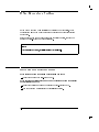
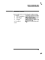
Contacting Agilent
By internet, phone, or fax, get assistance with all your test and measurement needs.
Table 1-1 Contacting Agilent
Online assistance: www.agilent.com/find/assist
United States
(tel) 1 800 452 4844
Latin America
(tel) (305) 269 7500
(fax) (305) 269 7599
Canada
(tel) 1 877 894 4414
(fax) (905) 282-6495
New Zealand
(tel) 0 800 738 378
(fax) (+64) 4 495 8950
Japan
(tel) (+81) 426 56 7832
(fax) (+81) 426 56 7840
Australia
(tel) 1 800 629 485
(fax) (+61) 3 9210 5947
Europe
(tel) (+31) 20 547 2323
(fax) (+31) 20 547 2390
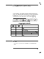
Asia Call Center Numbers
Country
Phone Number
Fax Number
Singapore
1-800-375-8100
(65) 836-0252
Malaysia
1-800-828-848
1-800-801664
Philippines
(632) 8426802
1-800-16510170 (PLDT
Subscriber Only)
(632) 8426809
1-800-16510288 (PLDT
Subscriber Only)
Thailand
(088) 226-008 (outside Bangkok)
(662) 661-3999 (within Bangkok)
(66) 1-661-3714
Hong Kong
800-930-871
(852) 2506 9233
Taiwan
0800-047-866
(886) 2 25456723
People’s Republic
of China
800-810-0189 (preferred)
10800-650-0021
10800-650-0121
India
1-600-11-2929
000-800-650-1101
2
Chapter 1
User's Guide
HP 83711A/12A and
HP 83711B/12B
Synthesized CW
Generators
HP part number: 83711-90131
Printed in USA July 1997 Supersedes April 1995
Notice.
The information contained in this document is subject to change without
notice.
Hewlett-Packard makes no warranty of any kind with regard to this material,
including but not limited to, the implied warranties of merchantability and
tness for a particular purpose. Hewlett-Packard shall not be liable for errors
contained herein or for incidental or consequential damages in connection
with the furnishing, performance, or use of this material.
c Copyright Hewlett-Packard Company 1995, 1997
All Rights Reserved. Reproduction, adaptation, or translation without prior
written permission is prohibited, except as allowed under the copyright laws.
1400 Fountaingrove Parkway, Santa Rosa, CA 95403-1799, USA
The HP 83711A/12A and HP 83711B/12B
Synthesized CW Generators
The HP 83711A/12A and HP 83711B/12B synthesized CW generators are
referred to as \synthesizers" throughout this manual. The HP 83711A/11B
has a carrier frequency range of 1 GHz to 20 GHz and the HP 83712A/12B has
a carrier frequency range of 10 MHz to 20 GHz. Specication information can
be found in Chapter 4, \Specications and Options."
The HP 83711A/12A and HP 83711B/12B Synthesized CW Generators User's
Guide is written to accommodate the novice and the expert user. If you
are unfamiliar with the synthesizer, Chapter 2, \Performing Fundamental
Synthesizer Operations," is useful. If you are familiar with the synthesizer,
Chapter 3, \Generating Signals with the Synthesizer" section is helpful. If
you are looking for specic, detailed information about the synthesizer, refer
to the remaining chapters as needed.
Notes
1. This manual applies to instruments with rmware revision 10.0 or greater.
2. If you have an HP 83711A/12A instrument with rmware revision number
(5960-7088).
3. To view rmware revision, press 4SPCL5, 415, 4HZ5 (ENTER).
< 10.0, refer to the
HP 83711A/12A Synthesized Signal Generator User's Guide
iii
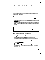
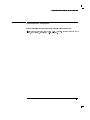
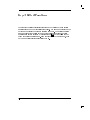
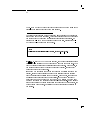
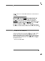
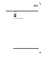
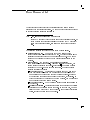
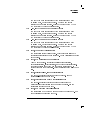
The Synthesizer at a Glance
The following gure and accompanying text explains some features of the
HP 83711A and HP 83711B. The HP 83712A andHP 83712B are nearly
identical.
HP 83711B Synthesized CW Generator
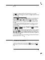
iv
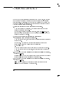
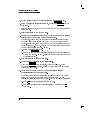
MSG
5 key allows you to display
1. The 4
any error messages on the front panel display.
Error messages are generated when you
perform a keystroke sequence that is not
valid, try to operate the synthesizer in a
mode that is not allowed, etc.
SHIFT
5 key changes the function
2. The 4
of some of the keys. When you press the
4
5 key and then press another key,
the synthesizer performs the function printed
in blue above the key.
SHIFT
RECALL
5 / SAVE key is used to
The 4
save most of the synthesizer operating
parameters in one of nine nonvolatile register
locations so that they can be recalled and
used at a later time.
3.
The Automatic Level Control keys select
the method used to regulate the synthesizer
output power level. Either internal leveling,
external power meter leveling, or external
diode detector leveling can be selected.
Additional external equipment is required
when either external power meter leveling or
external diode detector leveling is used.
4.
These keys set the carrier frequency and
RF output power level of the synthesizer.
5.
The display shows the current values of
synthesizer parameters as well as the status
of many of the synthesizer functions. The
display shows the current carrier frequency
and output power level. The annunciators
that appear below the parameters are only
visible when their associated function is active.
6.
(
)
The 4 5 and 4 5 keys move the cursor
that is over one of the digits in the display
either to the right or left when pressed. The
digit that is under the cursor will be modied
when the knob is rotated. If no cursor
appears in the display, parameter entry or
modication has been inhibited.
7.
The RF OUTPUT connector mates with a
Type-N male connector on non-Option 1E9
instruments. The connector mates with a
female APC-3.5 mm precision connector on
instruments with Option 1E9 installed.
8.
The knob is used to increase or decrease
the digit under the cursor ( 9 ) in the
display in steps of one.
9.
The data entry keys are used to enter
and modify various synthesizer parameters.
5 key cancels all or
The 4
part of an erroneous parameter entry before
it has been terminated. The terminator keys
(the right-most column of keys) are used to
choose the units for the entered parameter
as well as to terminate the parameter entry.
5 keys
The 4 5, 4 5, and 4
are used to increase or decrease a parameter
in predetermined steps.
10.
BACKSPACE
* +
STEP SIZE
The Automatic Level Control voltage input
(ALC IN) connector is used as the feedback
path to the synthesizer when its RF output
power level is being leveled externally.
11.
SPCL
5 key is used to initiate the
The 4
activation of several special functions available
in the synthesizer. Special functions are
additional functions that are not activated by
pressing a front panel key or shifted key.
12.
The POWER switch (LINE on an HP
83711A/12A) turns the synthesizer either on
or o.
13.
Synthesizer rear panel features are depicted and described in detail in
Chapter 5, \Front/Rear Panel," in this book.
v
In This Book
This book is divided into the following chapters:
Chapter 1, \Installing and Verifying the Synthesizer," contains procedures
for installing the synthesizer and verifying its operation.
Chapter 2, \Performing Fundamental Synthesizer Operations," familiarizes
you with the fundamental operation of the synthesizer.
Chapter 3, \Generating Signals with the Synthesizer," explains how to
generate CW signals and level signals.
Chapter 4, \Specications and Options," contains a list of the synthesizer
performance specications as well as the various mechanical, electrical,
warranty, and documentation options that are available.
Chapter 5, \Front/Rear Panel," contains entries that explain dierent
aspects of the synthesizer front and rear panel. (For example, you turn to
this chapter for information on the RF connectors).
Chapter 6, \Keys/Shifted Functions," contains entries on the function of
each key on the synthesizer front panel as well as the shifted or alternate
function of certain keys.
Chapter 7, \Special Functions," contains entries on the special functions
available in the synthesizer. Special functions are hidden during normal
instrument operation and can only be invoked by typing a specic key
sequence on the synthesizer front panel.
Chapter 8, \Error Messages," contains a table that lists all of the error
messages that might be generated during use of the instrument. Each table
entry contains a sequence that can be followed to recover from the error
condition.
Chapter 9, \Legal and Regulatory Information," contains information
related to safety and SCPI conformance information. The product warranty
is also contained in this chapter.
vi
Contents
1. Installing and Verifying the Synthesizer
Installing the Synthesizer . . . . .
To Unpack the Synthesizer . . .
To Install the Synthesizer . . .
Verifying Synthesizer Functionality
If You Encounter a Problem . . .
Mechanical or Electrical Damage
Power-up Problems . . . . . .
Self Test Failures . . . . . . .
.
.
.
.
.
.
.
.
.
.
.
.
.
.
.
.
.
.
.
.
.
.
.
.
.
.
.
.
.
.
.
.
.
.
.
.
.
.
.
.
.
.
.
.
.
.
.
.
2. Performing Fundamental Synthesizer Operations
To Enter Data with the Numeric Keypad .
To Modify Data with the Knob . . . . .
To Modify Data with the Arrow Keys . .
To Save and Recall Synthesizer States . .
Programming Example . . . . . . . .
To Read the Contents of the Error Queue
Programming Example . . . . . . . .
To Set the HP-IB Address . . . . . . .
Programming Example . . . . . . . .
If You Encounter a Problem . . . . . .
Data Entry Problems . . . . . . . .
Programming Problems . . . . . . .
.
.
.
.
.
.
.
.
.
.
.
.
.
.
.
.
.
.
.
.
.
.
.
.
.
.
.
.
.
.
.
.
1-3
1-3
1-5
1-7
1-8
1-8
1-9
1-11
.
.
.
.
.
.
.
.
.
.
.
.
.
.
.
.
.
.
.
.
.
.
.
.
.
.
.
.
.
.
.
.
.
.
.
.
.
.
.
.
.
.
.
.
.
.
.
.
.
.
.
.
.
.
.
.
.
.
.
.
.
.
.
.
.
.
.
.
.
.
.
.
.
.
.
.
.
.
.
.
.
.
.
.
2-3
2-4
2-6
2-8
2-9
2-10
2-11
2-12
2-12
2-13
2-13
2-15
To Generate a CW Signal . . . . . . . .
To Generate Millimeter Signals . . . . . .
To Use External Diode Detector Leveling . .
Programming Command . . . . . . . .
Related Tasks . . . . . . . . . . . . .
To Use External Power Meter Leveling . . .
Programming Commands . . . . . . . .
Related Tasks . . . . . . . . . . . . .
To Use the Level Correct Routine . . . . .
Related Tasks . . . . . . . . . . . . .
To Use Previously Stored Level Correct Data
.
.
.
.
.
.
.
.
.
.
.
.
.
.
.
.
.
.
.
.
.
.
.
.
.
.
.
.
.
.
.
.
.
.
.
.
.
.
.
.
.
.
.
.
.
.
.
.
.
.
.
.
.
.
.
.
.
.
.
.
.
.
.
.
.
.
3-3
3-4
3-7
3-10
3-10
3-11
3-13
3-13
3-14
3-19
3-20
3. Generating Signals with the Synthesizer
Contents-1
Related Tasks . . . . .
If You Encounter a Problem
Annunciators Turned On
RF Output Problems .
4. Specications and Options
.
.
.
.
. . . .
. . . . .
. . . .
. . . .
.
.
.
.
.
.
.
.
.
.
.
.
.
.
.
.
.
.
.
.
.
.
.
.
.
.
.
.
. .
. .
. .
. .
HP 83711A/11B Specications . . . . . . . . . . .
Frequency . . . . . . . . . . . . . . . . . . .
RF Output . . . . . . . . . . . . . . . . . . .
Spectral Purity . . . . . . . . . . . . . . . . .
HP 83712A/12B Specications . . . . . . . . . . .
Frequency . . . . . . . . . . . . . . . . . . .
RF Output . . . . . . . . . . . . . . . . . . .
Spectral Purity . . . . . . . . . . . . . . . . .
General . . . . . . . . . . . . . . . . . . . .
Front Panel Connectors . . . . . . . . . . . . .
Rear Panel Connectors . . . . . . . . . . . . . .
Options . . . . . . . . . . . . . . . . . . . . .
Electrical Options . . . . . . . . . . . . . . . .
Option 1E1 - Add Output Step Attenuator . . . .
Option 1E5 - Add High Stability Timebase . . . .
Option 1E8 - 1 Hz Frequency Resolution . . . . .
Option 1E9 - 3.5 mm RF Output Connector . . .
Mechanical Options . . . . . . . . . . . . . . .
Option 1CM - Rack Mount Kit . . . . . . . . .
Option 1CP - Rack Mount and Handle Kit . . . .
Option 1CR - Rack Slide Kit . . . . . . . . . .
Warranty Options . . . . . . . . . . . . . . . .
Option W30 - Two Additional Years Return-to-HP
Service . . . . . . . . . . . . . . . . . .
Option W32 - Three Year Return-to-HP Calibration
Service . . . . . . . . . . . . . . . . . .
Documentation Options . . . . . . . . . . . . .
Option OB0 - Delete Operating Documentation . .
Option OB1 - Extra Operating Documentation . .
Option OBV - Component-Level Information Packet
(CLIP) . . . . . . . . . . . . . . . . . .
Option OBW - Service Documentation . . . . . .
Option OBX - Component-Level Information Packet
(CLIP)/Service Documentation . . . . . . .
Contents-2
3-21
3-22
3-22
3-23
.
.
.
.
.
.
.
.
.
.
.
.
.
.
.
.
.
.
.
.
.
.
4-3
4-3
4-4
4-6
4-9
4-9
4-10
4-13
4-17
4-18
4-19
4-20
4-20
4-20
4-20
4-20
4-21
4-21
4-21
4-21
4-21
4-22
.
4-22
.
.
.
.
4-22
4-22
4-22
4-23
.
.
4-23
4-23
.
4-23
5. Front/Rear Panel
Annunciators . . . . . . . . . . .
See Also . . . . . . . . . . . . . .
Connectors . . . . . . . . . . . .
Coaxial Connectors . . . . . . .
HP-IB Connector . . . . . . . .
Display . . . . . . . . . . . . .
See Also . . . . . . . . . . . .
Knob . . . . . . . . . . . . . .
Equivalent SCPI Command . . . .
See Also . . . . . . . . . . . .
POWER Switch . . . . . . . . . .
See Also . . . . . . . . . . . .
Power Cables . . . . . . . . . . .
6. Keys/Shifted Functions
)
. . . . . . . . . . . . .
Equivalent SCPI Command .
See Also . . . . . . . . .
( . . . . . . . . . . . . .
Equivalent SCPI Command .
See Also . . . . . . . . .
* . . . . . . . . . . . . .
Equivalent SCPI Commands
See Also . . . . . . . . .
+ . . . . . . . . . . . . .
Equivalent SCPI Commands
See Also . . . . . . . . .
ADDRESS . . . . . . . . .
Equivalent SCPI Command .
See Also . . . . . . . . .
BACK SPACE . . . . . . .
Equivalent SCPI Command .
See Also . . . . . . . . .
ENTER (Hz) . . . . . . . .
Equivalent SCPI Command .
See Also . . . . . . . . .
ENTRY OFF . . . . . . . .
Equivalent SCPI Command .
See Also . . . . . . . . .
EXT DIODE . . . . . . . .
.
.
.
.
.
.
.
.
.
.
.
.
.
.
.
.
.
.
.
.
.
.
.
.
.
.
.
.
.
.
.
.
.
.
.
.
.
.
.
.
.
.
.
.
.
.
.
.
.
.
.
.
.
.
.
.
.
.
.
.
.
.
.
.
.
.
.
.
.
.
.
.
.
.
.
.
.
.
.
.
.
.
.
.
.
.
.
.
.
.
.
.
.
.
.
.
.
.
.
.
.
.
.
.
.
.
.
.
.
.
.
.
.
.
.
.
.
.
.
.
.
.
.
.
.
.
.
.
.
.
.
.
.
.
.
.
.
.
.
.
.
.
.
.
.
.
.
.
.
.
.
.
.
. . .
. . .
. . .
. . .
. . .
. . .
. . .
. . .
. . .
. . .
. . .
. . .
. . .
5-3
5-5
5-6
5-7
5-8
5-11
5-12
5-13
5-13
5-14
5-15
5-15
5-16
.
.
.
.
.
.
.
.
.
.
.
.
.
.
.
.
.
.
.
.
.
.
.
.
.
.
.
.
.
.
.
.
.
.
.
.
.
.
.
.
.
.
.
.
.
.
.
.
.
.
.
.
.
.
.
.
.
.
.
.
.
.
.
.
.
.
.
.
.
.
.
.
.
.
.
.
.
.
.
.
.
.
.
.
.
.
.
.
.
.
.
.
.
.
.
.
.
.
.
.
.
.
.
.
.
.
.
.
.
.
.
.
.
.
.
.
.
.
.
.
.
.
.
.
.
.
.
.
.
.
.
.
.
.
.
.
.
.
.
.
.
.
.
.
.
.
.
.
.
.
.
.
.
.
.
.
.
.
.
.
.
.
.
.
.
.
.
.
.
.
.
.
.
.
.
6-3
6-4
6-4
6-5
6-6
6-6
6-7
6-7
6-8
6-9
6-9
6-10
6-11
6-11
6-11
6-12
6-12
6-12
6-13
6-13
6-14
6-15
6-15
6-15
6-16
.
.
.
.
.
.
.
.
.
.
.
.
.
.
.
.
.
.
.
.
.
.
.
.
.
.
.
.
.
.
.
.
.
.
.
.
.
.
.
.
.
.
.
.
.
.
.
.
.
.
Contents-3
External Diode Detector Leveling . . . .
Applications . . . . . . . . . . . . . . .
Advantages of Diode Detector Leveling . .
Disadvantages of Diode Detector Leveling
Equivalent SCPI Command . . . . . . .
See Also . . . . . . . . . . . . . . .
EXT METER . . . . . . . . . . . . . .
External Power Meter Leveling . . . . .
Applications . . . . . . . . . . . . .
External Equipment Limitations . . . .
Power Meter . . . . . . . . . . . .
Power Sensor . . . . . . . . . . . .
Advantages of Power Meter Leveling . . .
Disadvantages of Power Meter Leveling . .
Equivalent SCPI Commands . . . . . .
See Also . . . . . . . . . . . . . . .
FREQ . . . . . . . . . . . . . . . . .
Equivalent SCPI Command . . . . . . .
See Also . . . . . . . . . . . . . . .
INT LEVEL . . . . . . . . . . . . . .
Advantages of Internal Leveling . . . . .
Disadvantages of Internal Leveling . . . .
Equivalent SCPI Commands . . . . . .
See Also . . . . . . . . . . . . . . .
LOCAL . . . . . . . . . . . . . . . .
Equivalent SCPI Command . . . . . . .
See Also . . . . . . . . . . . . . . .
LVL CR . . . . . . . . . . . . . . . .
Equivalent SCPI Command . . . . . . .
See Also . . . . . . . . . . . . . . .
LVL CR ON/OFF . . . . . . . . . . . .
Equivalent SCPI Commands . . . . . .
See Also . . . . . . . . . . . . . . .
MSG . . . . . . . . . . . . . . . . .
Equivalent SCPI Command . . . . . . .
See Also . . . . . . . . . . . . . . .
MULTIPLIER . . . . . . . . . . . . .
Equivalent SCPI Command . . . . . . .
See Also . . . . . . . . . . . . . . .
Numeric Keypad . . . . . . . . . . . .
See Also . . . . . . . . . . . . . . .
Contents-4
.
.
.
.
.
.
.
.
.
.
.
.
.
.
.
.
.
.
.
.
.
.
.
.
.
.
.
.
.
.
.
.
.
.
.
.
.
.
.
.
.
.
.
.
.
.
.
.
.
.
.
.
.
.
.
.
.
.
.
.
.
.
.
.
.
.
.
.
.
.
.
.
.
.
.
.
.
.
.
.
.
.
.
.
.
.
.
.
.
.
.
.
.
.
.
.
.
.
.
.
.
.
.
.
.
.
.
.
.
.
.
.
.
.
.
.
.
.
.
.
.
.
.
.
.
.
.
.
.
.
.
.
.
.
.
.
.
.
.
.
.
.
.
.
.
.
.
.
.
.
.
.
.
.
.
.
.
.
.
.
.
.
.
.
. .
. .
. .
. .
. .
. .
. .
. .
. .
. .
. .
. .
. .
. .
. .
. .
. .
. .
. .
. .
. .
. .
. .
. .
. .
. .
. .
. .
. .
. .
. .
. .
. .
. .
. .
. .
. .
. .
. .
. .
. .
6-16
6-17
6-18
6-18
6-19
6-19
6-20
6-20
6-22
6-22
6-22
6-22
6-23
6-23
6-24
6-24
6-25
6-26
6-26
6-27
6-28
6-28
6-29
6-29
6-30
6-30
6-30
6-31
6-34
6-34
6-35
6-36
6-36
6-37
6-37
6-37
6-38
6-39
6-39
6-40
6-40
POWER LEVEL . . . . . . . . .
Equivalent SCPI Command . . . . .
See Also . . . . . . . . . . . .
PRESET . . . . . . . . . . . . .
Equivalent SCPI Commands . . .
See Also . . . . . . . . . . . .
RCL CR . . . . . . . . . . . . .
Equivalent SCPI Command . . . .
See Also . . . . . . . . . . . .
RECALL . . . . . . . . . . . . .
Equivalent SCPI Command . . . .
See Also . . . . . . . . . . . .
RF ON/OFF . . . . . . . . . . .
Equivalent SCPI Command . . . .
See Also . . . . . . . . . . . .
SAVE . . . . . . . . . . . . . .
Equivalent SCPI Command . . . .
See Also . . . . . . . . . . . .
SAVE CR . . . . . . . . . . . .
Equivalent SCPI Command . . . .
See Also . . . . . . . . . . . .
SHIFT . . . . . . . . . . . . . .
Equivalent SCPI Command . . . .
See Also . . . . . . . . . . . .
SPCL . . . . . . . . . . . . . .
Equivalent SCPI Command . . . .
SPCL OFF (kHz) . . . . . . . . .
Equivalent SCPI Command . . . .
See Also . . . . . . . . . . . .
SPCL ON (MHz) . . . . . . . . .
Equivalent SCPI Command . . . .
See Also . . . . . . . . . . . .
STEP SIZE . . . . . . . . . . . .
Equivalent SCPI Commands . . .
See Also . . . . . . . . . . . .
.
.
.
.
.
.
.
.
.
.
.
.
.
.
.
.
.
.
.
.
.
.
.
.
.
.
.
.
.
.
.
.
.
.
.
.
.
.
.
.
.
.
.
.
.
.
.
.
.
.
.
.
.
.
.
.
.
.
.
.
.
.
.
.
.
.
.
.
.
.
.
.
.
.
.
.
.
.
.
.
.
.
.
.
.
.
.
.
.
.
.
.
.
.
.
.
.
.
.
.
.
.
.
.
.
.
.
.
.
.
.
.
.
.
.
.
.
.
.
.
.
.
.
.
.
.
.
.
.
.
.
.
.
.
.
.
.
.
.
.
.
.
.
.
.
.
.
.
.
.
.
.
.
.
.
.
.
.
.
.
.
.
.
.
.
.
.
.
.
.
.
.
.
.
.
.
.
.
.
.
.
.
.
.
.
.
.
.
.
.
.
.
.
.
.
.
.
.
.
.
.
.
.
.
.
.
.
.
.
.
.
.
.
.
.
.
.
.
.
.
.
.
.
.
.
.
.
.
.
.
.
.
.
.
.
.
.
.
.
.
.
.
.
.
.
. .
. .
. .
. .
. .
. .
. .
. .
. .
. .
. .
. .
. .
. .
. .
. .
. .
. .
. .
. .
. .
. .
. .
. .
. .
. .
. .
. .
. .
. .
. .
. .
. .
. .
. .
6-41
6-42
6-42
6-43
6-44
6-44
6-45
6-46
6-46
6-47
6-47
6-47
6-48
6-48
6-48
6-49
6-49
6-49
6-50
6-51
6-51
6-52
6-52
6-52
6-53
6-53
6-54
6-54
6-55
6-56
6-56
6-56
6-57
6-57
6-58
Contents-5
7. Special Functions
ATTEN HOLD ON/OFF . . . . .
Applications . . . . . . . . . .
Advantages . . . . . . . . . . .
Disadvantages . . . . . . . . . .
Equivalent SCPI Command . . . .
See Also . . . . . . . . . . . . . .
CLEAR DISPLAY . . . . . . . .
Equivalent SCPI Command . . . .
See Also . . . . . . . . . . . .
ERASE MEMORY . . . . . . . .
Application . . . . . . . . . . .
Equivalent SCPI Command . . . .
See Also . . . . . . . . . . . .
PWR MTR ADDRS . . . . . . . .
Equivalent SCPI Command . . . .
See Also . . . . . . . . . . . .
PWR MTR SELECT . . . . . . .
Equivalent SCPI Command . . . .
See Also . . . . . . . . . . . .
REMOTE LANGUAGE . . . . . .
Equivalent SCPI Command . . . .
See Also . . . . . . . . . . . .
SELF TEST . . . . . . . . . . .
Equivalent SCPI Command . . . .
See Also . . . . . . . . . . . .
Service-Related Special Functions . .
See Also . . . . . . . . . . . .
SHOW INFO . . . . . . . . . . .
Equivalent SCPI Command . . . .
See Also . . . . . . . . . . . .
.
.
.
.
.
.
.
.
.
.
.
.
.
.
.
.
.
.
.
.
.
.
.
.
.
.
.
.
.
.
.
.
.
.
.
.
.
.
.
.
.
.
.
.
.
.
.
.
.
.
.
.
.
.
.
.
.
.
.
.
.
.
.
.
.
.
.
.
.
.
.
.
.
.
.
.
.
.
.
.
.
.
.
.
.
.
.
.
.
.
.
.
.
.
.
.
.
.
.
.
.
.
.
.
.
.
.
.
.
.
.
.
.
.
.
.
.
.
.
.
.
.
.
.
.
.
.
.
.
.
.
.
.
.
.
.
.
.
.
.
.
.
.
.
.
.
.
.
.
.
.
.
.
.
.
.
.
.
.
.
.
.
.
.
.
.
.
.
.
.
.
.
.
.
.
.
.
.
.
.
.
.
.
.
.
.
.
.
.
.
.
.
.
.
.
.
.
.
.
.
.
.
.
.
.
.
.
.
.
.
.
.
.
.
.
. .
. .
. .
. .
. .
. .
. .
. .
. .
. .
. .
. .
. .
. .
. .
. .
. .
. .
. .
. .
. .
. .
. .
. .
. .
7-3
7-4
7-4
7-5
7-5
7-5
7-6
7-7
7-7
7-8
7-8
7-8
7-9
7-10
7-11
7-11
7-12
7-12
7-13
7-14
7-14
7-14
7-15
7-16
7-16
7-17
7-17
7-18
7-18
7-18
Error Messages List . . . . . . . . . . . . . . . . .
Messages . . . . . . . . . . . . . . . . . . . . . .
8-3
8-5
8. Error Messages
Contents-6
.
.
.
.
.
9. Legal and Regulatory Information
Safety Symbols . . . . .
Miscellaneous Symbols .
Safety Considerations . .
Before Applying Power .
Safety Earth Ground . .
Cleaning the Product . .
Certication . . . . . .
Warranty . . . . . . . .
Limitation of Warranty
Exclusive Remedies . .
Assistance . . . . . . .
.
.
.
.
.
.
.
.
.
.
.
.
.
.
.
.
.
.
.
.
.
.
.
.
.
.
.
.
.
.
.
.
.
.
.
.
.
.
.
.
.
.
. . . . .
. . . .
. . . .
. . . .
. . . .
. . . .
.
.
.
.
.
.
.
.
.
.
.
.
.
.
.
.
.
.
.
.
.
.
.
.
.
.
.
.
.
.
.
.
.
.
.
.
.
.
.
.
.
.
.
.
.
.
.
.
.
.
.
.
.
.
.
.
.
.
.
.
.
.
.
.
.
.
.
.
.
.
.
.
.
.
.
.
. .
. .
. .
. .
. .
. .
9-3
9-4
9-5
9-5
9-5
9-6
9-7
9-8
9-8
9-9
9-10
Index
Contents-7
Figures
1-1.
3-1.
3-2.
3-3.
3-4.
4-1.
4-2.
4-3.
4-4.
4-5.
4-6.
4-7.
4-8.
4-9.
4-10.
4-11.
5-1.
5-2.
5-3.
5-4.
5-5.
5-6.
Line Fuse Removal and Replacement . . . . . . . . . . .
Millimeter-Wave Equipment Setup . . . . . . . . . . . . .
External Diode Detector Leveling Setup . . . . . . . . . .
External Power Meter Leveling Setup . . . . . . . . . . .
Level Correct Routine Equipment Setup . . . . . . . . . .
Typical Maximum Available Output Power from 1 to 20
GHz, at 25 C with Output Step Attenuator (Option 1E1)
Installed . . . . . . . . . . . . . . . . . . . . . .
Typical Output Level Accuracy and Flatness at +10 and 085
dBm . . . . . . . . . . . . . . . . . . . . . . . .
Typical single-sideband phase noise at 1 GHz, 10 GHz and 20
GHz, 25 C, CW mode. Osets less than 100 Hz require
the high stability timebase, Option 1E5. . . . . . . . .
Typical 2nd Harmonic Levels Measured at Output Power of +6
dBm . . . . . . . . . . . . . . . . . . . . . . . .
Typical Residual FM Measured in 50 Hz - 15 kHz Bandwidth,
CW Mode, with High Stability Timebase (Option 1E5) . .
Typical Maximum Available Output Power from 1 to 20
GHz, at 25 C with Output Step Attenuator (Option 1E1)
Installed . . . . . . . . . . . . . . . . . . . . . .
Typical Maximum Available Output Power from 0.01 to 1 GHz
at 25 C. . . . . . . . . . . . . . . . . . . . . . .
Typical Output Level Accuracy and Flatness at +10 and 085
dBm . . . . . . . . . . . . . . . . . . . . . . . .
Typical single-sideband phase noise at 50 MHz, 1 GHz, 10 GHz
and 20 GHz, 25 C, CW mode. Osets less than 100 Hz
require the high stability timebase, Option 1E5. . . . . .
Typical 2nd Harmonic Levels Measured at Output Power of +6
dBm . . . . . . . . . . . . . . . . . . . . . . . .
Typical Residual FM Measured in 50 Hz - 15 kHz Bandwidth,
CW mode, with High Stability Timebase (Option 1E5) . .
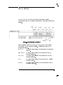
Synthesizer Display Annunciators . . . . . . . . . . . . .
Synthesizer Connectors - Front Panel . . . . . . . . . . .
Synthesizer Connectors - Rear Panel . . . . . . . . . . . .
HP-IB Connector and Cable . . . . . . . . . . . . . . . .
Synthesizer Display . . . . . . . . . . . . . . . . . . .
Power Cable and Line (Mains) Plug Part Numbers . . . . . .
Contents-8
1-10
3-4
3-8
3-11
3-15
4-4
4-5
4-6
4-7
4-8
4-10
4-11
4-12
4-14
4-15
4-16
5-3
5-6
5-6
5-8
5-11
5-17
Contents
6-1. External Diode Detector Leveling Setup . . . . . . . . . .
6-2. External Power Meter Leveling Setup . . . . . . . . . . .
6-17
6-21
Contents-9
Tables
4-1.
4-2.
4-3.
4-4.
5-1.
6-1.
7-1.
9-1.
Osets (HP 83711A only) . . . . . . . .
Osets (HP 83711B only) . . . . . . . .
Osets (HP 83712A only) . . . . . . . .
Osets (HP 83712B only) . . . . . . . .
HP-IB Interface Cables Available . . . .
PRESET Conditions . . . . . . . . . .
Service-Related Special Functions . . . .
Hewlett-Packard Sales and Service Oces
Contents-10
.
.
.
.
.
.
.
.
.
.
.
.
.
.
.
.
.
.
.
.
.
.
.
.
.
.
.
.
.
.
.
.
.
.
.
.
.
.
.
.
.
.
.
.
.
.
.
.
.
.
.
.
.
.
.
.
.
.
.
.
.
.
.
.
.
.
.
.
.
.
.
.
4-6
4-6
4-13
4-13
5-8
6-43
7-17
9-11
1
Installing and Verifying the
Synthesizer
Installing and Verifying the Synthesizer
This chapter contains procedures for properly installing your HP 83711A/12A
or HP 83711B/12B synthesizer and procedures for functional verication of
the instrument.
1-2
Installing the Synthesizer
This procedure explains how to inspect, install, and power-up the
synthesizer.
To Unpack the Synthesizer
1. Inspect the shipping container for damage.
Look for signs of damage such as a dented or torn shipping container or
cushioning material that shows signs of unusual stress or compacting.
2. Carefully remove the contents from the shipping container and inspect
each item for damage.
If the instrument or any accessories appear to be damaged, refer to
\Mechanical or Electrical Damage" at the end of this chapter. The
following items should have been received in the shipment.
1-3
Installing and Verifying the Synthesizer
Installing the Synthesizer
Item
Model/Part Number
Instrument
HP 83711A/12A
Power Cable
Depends on shipment destination. Refer to
\Power Cables"in Chapter 5 of this manual.
User's Guide
83711-90131
Quick Start Guide
83711-90133
Programming Guide
83711-90132
Calibration Guide
83731-90125
Calibration Kit
5063-1635
Calibration Guide
83731-90125
Calibration Software
5010-7723
or
HP 83711B/12B
Also includes one of the following:
Handle Kit
5062-3989 (standard)
Rack Mount Kit
5062-3977 (Option 1CM)
Rack Mount Kit with Handles
5062-3983 (Option 1CP)
Rack Slide Kit
1494-0059 (Option 1CR)
3. Keep the shipping materials for future use.
If undamaged, shipping materials are useful for shipment or storage of the
instrument. If damaged, shipping materials should be kept for the carrier's
inspection.
1-4
Installing and Verifying the Synthesizer
Installing the Synthesizer
To Install the Synthesizer
CAUTION
The following provides a general procedure for installation and initial power
up of the HP 83711A/12A or HP 83711B/12B synthesizer.
1. Check to make sure that the power cable is undamaged.
Do not use the power cable if the plug contacts are bent or broken or if
the wire insulation is damaged or if wire is exposed. Never use a power
cable if the grounding contact has been removed.
Always use the three-prong AC power cord supplied with this product.
Failure to ensure adequate earth grounding by not using this cord may cause
product damage.
2. Set the POWER switch (LINE on an HP 83711A/12A) on the
synthesizer to standby ( ).
3. Set the line voltage selector switch to match the mains voltage.
The line voltage selector switch is located on the rear panel of the
synthesizer to the right of the power module. Use a small at blade
screwdriver to set the switch up for mains voltages in the range of 90 V to
132 V; 50, 60, or 400 Hz or down for mains voltages in the range of 198 V
to 264 V; 50 or 60 Hz.
1-5
Installing and Verifying the Synthesizer
Installing the Synthesizer
WARNING
This is a Safety Class I product (provided with a protective earthing
ground incorporated in the power cord). The mains plug shall only be
inserted in a socket outlet provided with a protective earth contact. Any
interruption of the protective conductor inside or outside of the product
is likely to make the product dangerous. Intentional interruption is
prohibited.
4. Push the module end of the power cable into the power module on the
rear panel of the synthesizer until it is rmly seated.
5. Connect the plug end of the power cable to a suitable mains power
receptacle.
6. Set the POWER switch (LINE on an HP 83711A/12A) to on ( ).
When you turn the synthesizer on, the displays and annunciators light
momentarily and the ventilation fan starts. In addition, it is normal for the
LED annunciators (including the MSG LED) to turn on and then o during
a power-up test. (The MSG LED should be o when the power-up test is
complete.)
NOTE
Error message 940 TIMEBASE OVEN COLD will remain on after the power-up test if the
instrument has the Option 1E5 installed, and has been disconnected from the mains power. This error
should go away after a short warm-up period.
Once the power-up test is complete, frequency and power level will be
displayed in the right-most display and pulse parameters will be shown in
the display if pulse modulation is enabled.
1-6
Verifying Synthesizer Functionality
The verication procedure is suitable for incoming inspection; however,
you can refer to the HP 83711A/12A and 83711B/12B Synthesized CW
Generators Service Guide or the HP 83711A/12A, HP 83711B/12B, HP
83731A/32A, and HP 83731B/32B Synthesized CW Generators Calibration
Guide for procedures that test all warranted specications.
1. Activate the SELF TEST special function.
To activate the SELF TEST special function, perform the following
procedure.
5 key.
a. Press the 4
b. Press 4 5 on the synthesizer numeric keypad.
c. Terminate the special function entry by pressing the 4 5 (ENTER) key.
The display will read SELF TEST?, PRESS ENTER.
2. Press the ENTER key again to initiate the synthesizer self test routine.
When the self test routine is running, the display will alternately read
SELF TESTING and PRESETTING INSTRUMENT. After the test completes,
the display momentarily reads SELF TEST PASSED.
3. If the self test indicates an error condition, refer to the section entitled
\If You Encounter a Problem" at the end of this chapter.
If an error condition exists, the display will momentarily read
TEST XX = YY where XX and YY are numbers indicating the error
condition.
SPCL
5
Hz
1-7
If You Encounter a Problem
If you have a problem while installing or verifying the synthesizer, check
the following list of commonly encountered problems and troubleshooting
procedures.
If the problem that you encounter is not in the following list, contact the
nearest Hewlett-Packard oce for assistance.
NOTE
When transporting the product, use original packaging or comparable only.
Mechanical or Electrical Damage
If the instrument is mechanically or electrically damaged:
Contact the nearest Hewlett-Packard oce.
If the shipping materials are damaged and the instrument is mechanically
or electrically damaged:
Contact the carrier as well as the nearest Hewlett-Packard oce.
Keep the shipping materials for the carrier's inspection.
1-8
Installing and Verifying the Synthesizer
If You Encounter a Problem
Power-up Problems
If the synthesizer has no power:
Check that the power cord is fully seated in both the mains power
receptacle and the synthesizer power module.
Check that the synthesizer line fuse is not open.
WARNING
For continued protection against re hazard, replace line fuse only with
same type and ratings (type nA/nV). The use of other fuses or materials is
prohibited.
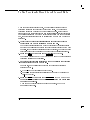
Refer to Figure 1-1 to remove the fuse from the power module. You can use
a continuity light or an ohmmeter to check the fuse. An ohmmeter should
read very close to zero ohms if the fuse is good. The 6.3A, 250 V fuse is
HP part number 2110-0703.
1-9
Installing and Verifying the Synthesizer
If You Encounter a Problem
Figure 1-1. Line Fuse Removal and Replacement
Contact the nearest Hewlett-Packard oce for service, if necessary.
If the display lights, but the ventilation fan does not start:
Check that the fan is not stuck. To check the fan, follow these steps:
1. Set the POWER switch (LINE on an HP 83711A/12A) to standby ( ).
2. Check that the fan blades are not jammed.
Contact the nearest Hewlett-Packard oce for service, if necessary.
1-10
Installing and Verifying the Synthesizer
If the synthesizer MSG LED annunciator remains on after the power-up
test is complete:
NOTE
Error message 940 TIMEBASE OVEN COLD will remain on after the power-up test if the
instrument has the Option 1E5 installed, and has been disconnected from the mains power. This error
should go away after a short warm-up period.
If the synthesizer MSG annunciator is on, there is a problem with the
synthesizer. To determine the error and turn o the MSG annunciator, refer
to \To Read the Contents of the Error Queue" in Chapter 2 and the listing of
error messages in Chapter 8.
Self Test Failures
If the Self Test Fails:
Check the contents of the error queue for error messages.
To determine errors and clear them, refer to \To Read the Contents of the
Error Queue" in Chapter 2 and the listing of error messages in Chapter 8.
1-11
Installing and Verifying the Synthesizer
2
Performing Fundamental
Synthesizer Operations
Performing Fundamental Synthesizer Operations
This chapter describes fundamental synthesizer operations. The purpose
of this chapter is to familiarize you with the fundamental operation of the
synthesizer. Procedures cover how to enter or modify data, how to set the
HP-IB address, how to save and recall instrument states, etc.
NOTE
This product has been designed and tested in accordance with IEC Publication 1010, Safety
Requirements for Electronic Measuring Apparatus, and has been supplied in a safe condition. The
instruction documentation contains information and warnings which must be followed by the user to
ensure safe operation and to maintain the product in a safe condition.
WARNING
If this product is not used as specied, the protection provided by the
equipment could be impaired. This product must be used in a normal
condition (in which all means for protection are intact) only.
2-2
To Enter Data with the Numeric Keypad
The synthesizer numeric keypad and units terminator keys provide one way
to enter function parameters.
1. Select the desired function key or shifted function key.
The function must have a numeric value (parameter) associated with
5 and
it in order to enter a new value with the numeric keypad. 4
4
5 are examples of functions with parameters.
For example, to select power level so that its parameter is active, press the
5 key.
4
Notice that a cursor ( 9 ) appears over one of the digits in the power level
display. The cursor will always appear over one of the digits of the active
parameter.
FREQ
POWER LEVEL
POWER LEVEL
NOTE
Two cursors will appear ( 9 9 ) when the cursor is positioned o the display.
2. Enter the desired value of the parameter by pressing the numeric keys
and, if necessary, the negative and decimal keys.
Notice that, as you press the keys, the display shows the numbers that are
entered.
3. Press the appropriate units terminator key to enter the value.
The units terminator keys appear to the right side of the numeric keypad.
The following steps show how to enter a value of 09.5 dBm for power
level:
5 key.
a. Press the 4
b. Press 40 5 on the numeric keypad.
c. Press the dBm (4 5) key to terminate the entry.
Once you terminate the entry, the synthesizer updates the power level
value to 09.5 dBm.
POWER LEVEL
9.5
GHz
2-3
To Modify Data with the Knob
The knob on the synthesizer front panel is used to modify data. You turn the
knob in order to increase or decrease the parameter value of the currently
active function. Additionally, you can modify the position of the cursor ( 9 )
that is over the active parameter in order to increase or decrease the rate at
which the function parameter changes.
1. Select the function key of the parameter to be modied.
When the function key is selected, the cursor appears over one of the
digits of the selected parameter.
5 key. The
For example, to select the frequency function, press the 4
frequency parameter is selected when the cursor appears over one of the
digits of the frequency display.
2. Turn the knob clockwise to increase the parameter or
FREQ
counterclockwise to decrease the parameter.
When you turn the knob, the digit under the cursor increases or decreases
in steps of one.
For example, when frequency is in its preset state and is the active
parameter, the frequency display shows the following:
3.000000000 GHz
where the cursor appears over the third \0" to the right of the decimal.
When you turn the knob in this case, the output frequency changes in 1
MHz steps.
3. If you wish to move the position of the cursor one position to the right,
press the 4)5 key.
Pressing 4)5 once moves the position of the cursor to the right one digit in
order to decrease the knob resolution by a factor of ten.
4. If you wish to move the position of the cursor one position to the left,
press the 4(5 key.
(5 moves the position of the cursor to the left one digit in order to
increase the knob resolution by a factor of ten.
4
2-4
Performing Fundamental Synthesizer Operations
To Modify Data with the Knob
5. Continue to press the 4)5 or 4(5 key until the cursor is positioned over
the desired digit.
For example, suppose that frequency is the current active parameter, and
you wish to change the cursor position from 1 MHz to 1 GHz. The steps
that follow illustrate how to accomplish this:
5 key.
a. Press the 4
When the instrument has been set to the preset state, the frequency
display indicates the following:
3.000000000 GHz
where the cursor appears over the third \0" to the right of the decimal.
b. Press the 4(5 key three times. This moves the cursor from the position
corresponding to MHz to the position corresponding to GHz. (The
cursor is now over the \3".)
c. Rotate the knob slowly so that you can see the frequency change in 1
GHz steps.
PRESET
NOTE
* +
* +
The Knob and 4 5, 4 5 keys operate independently of each other. The 4 5, 4 5 keys increase or
decrease parameters in dened steps.
2-5
To Modify Data with the Arrow Keys
The synthesizer 4*5 and 4+5 (arrow) keys increase or decrease the value of the
5 key. The
currently active parameter by an amount set with the 4
5 key is referred to as the increment value.
amount set with the 4
1. Select the function key of the parameter to be modied.
When the function key is selected, a cursor
( 9 ) appears over one of the digits of the selected parameter.
5 key. The
For example, to select the frequency function, press the 4
frequency parameter is selected when the cursor appears over one of the
digits of the frequency display.
2. Press the 4*5 key to increase the parameter by the current increment
STEP SIZE
STEP SIZE
FREQ
value or press the 4+5 key to decrease the parameter by the current
increment value.
For example, when frequency is in its preset state, the frequency display
shows the following:
3.000000000 GHz
where the cursor appears over the third \0" to the right of the decimal.
The preset frequency increment value is 100 MHz. When you press the 4*5
key, the value of frequency increases to 3.100000000 GHz.
3. If you wish to change the increment value, you can do so using the
4STEP
5
SIZE
key.
The 4
5 key allows you to change the increment value of the
currently active function. For example, suppose that frequency is the
current active parameter, and you wish to change the increment value
from its preset value of 100 MHz to 250 MHz. The steps that follow
illustrate how to accomplish this:
a. Press the 4
5 key.
b. Type 4 5 on the synthesizer numeric keypad.
STEP SIZE
STEP SIZE
250
2-6
Performing Fundamental Synthesizer Operations
To Modify Data with the Arrow Keys
c. Terminate the frequency increment value entry by pressing the 4 5
key.
When either the 4*5 or 4+5 key is pressed, the frequency will be either
increased or decreased by 250 MHz instead of 100 MHz.
MHz
NOTE
* +
The knob and 4 5, 4 5 keys operate independently of each other. The knob increases or decreases
the digit in the display that is under the cursor.
2-7
To Save and Recall Synthesizer States
When you use the synthesizer for a specic application, you can save and
then recall the instrument state for future use. You can save up to ten
dierent instrument states.
1. Press the 4
5 key and then the 4
5 (SAVE) key.
When 4
5, 4
5 (SAVE) is pressed, the text SAVE STATE IN REG
XXX is shown on the synthesizer display where XXX is the last register
number entered.
2. Use the numeric keypad to enter the desired register number.
Valid register numbers are 0 through 9.
3. Press the 4 5 (ENTER) key to terminate the entry.
5 key.
4. To recall the instrument state from memory, press the 4
When 4
5 is pressed, the text RECALL STATE FROM REG XX is shown
on the synthesizer display where XX is the last register recalled.
5. Use the numeric keypad to enter the desired register number.
6. Press the 4 5 (ENTER) key to terminate the entry.
SHIFT
SHIFT
RECALL
RECALL
Hz
RECALL
RECALL
Hz
Notes
1. When an instrument state is saved to an instrument state register, it will write over any instrument
state previously stored to that register.
2. If an instrument state has not been previously stored to an instrument state register, the
synthesizer will be set to the preset state if you attempt to recall the instrument state from that
register.
2-8
Performing Fundamental Synthesizer Operations
To Save and Recall Synthesizer States
Programming Example
Use the following commands to store the instrument state to register 9 and
then recall it from register 9:
OUTPUT 719; "*SAV 9"
OUTPUT 719; "*RCL 9"
Saves the current instrument state to register #9.
Recalls the previously stored instrument state
from register #9.
2-9
To Read the Contents of the Error Queue
When one or more error messages are stored in the synthesizer error queue,
the front panel MSG LED annunciator will light. Once all error messages
have been read and all error conditions have been corrected, the MSG
annunciator will turn o.
1. Press the 4 5 key.
When the 4 5 key is pressed, the most recent uncleared manual error
number and the front panel error message will appear on the display.
2. Look up the manual error number in the table in Chapter 8.
Chapter 8 is organized in ascending manual error number order.
3. Perform the instructions following the error message in the list to
MSG
MSG
correct or clear the error condition.
After you have completed the procedure in the list, return to this
procedure to continue.
4. If the MSG LED annunciator is still lit, perform steps 1 through 3 again
until the MSG annunciator turns o. If the MSG annunciator is turned
o, continue with the next step.
5. Press the 4 5 key one more time.
MSG
Pressing the 4
5
MSG
key again returns the display to normal operation.
NOTE
In the case of unleveled power or unlocked frequency, the MSG LED annunciator may remain lit
continuously until the problem is corrected.
2-10
Performing Fundamental Synthesizer Operations
To Read the Contents of the Error Queue
Programming Example
To read the entire contents of the error queue, run the following program:
10 DIM B$[160]
20
OUTPUT 719; "SYST:ERR?"
30
ENTER 719; A,B$
40
PRINT A,B$
50 IF A<>0 THEN 20
60 END
Dimensions array B$ to accept 160 characters.
Queries the oldest uncleared error number and
message in the HP-IB error queue.
Enters the error number into variable A and the
HP-IB error message into variable B$.
Prints the error number and HP-IB error message to the controller screen.
Returns to line 20 if there are more errors in the
queue.
2-11
To Set the HP-IB Address
The synthesizer default HP-IB address is preset to 19. You can, however,
change the HP-IB address of the synthesizer from the front panel.
1. Press the 4
5 key on the synthesizer front panel.
2. Press the ADDRESS (4
5) key.
5 key is pressed
The display indicates HPIB ADDRESS XX when the 4
where XX is the current HP-IB address.
3. Enter the desired HP-IB address using the numeric keypad.
For example, if you want to set the synthesizer HP-IB address to 12, type
4 5 on the numeric keypad.
The display indicates HPIB ADDRESS 12.
4. Terminate the HP-IB address entry by pressing the 4 5 (ENTER) key.
Note that when 4 5 (ENTER) is pressed, the cursor appears over the
address parameter in the display. The synthesizer HP-IB address is now
set to the new value (12 in the example), but you can still change it with
the numeric keypad, knob, or arrow keys at this point. Pressing 4 5
(ENTER) again returns the display to normal operation.
SHIFT
LOCAL
LOCAL
12
Hz
Hz
Hz
Programming Example
To set the synthesizer HP-IB address to 12, send the following command:
OUTPUT 719; "SYST:COMM:GPIB:ADDR 12"
2-12
Sets the synthesizer HP-IB address to 12.
If You Encounter a Problem
If you have a problem operating the synthesizer, check the following list of
commonly encountered problems and troubleshooting procedures. If the
problem that you encounter is not in the following list, contact the nearest
Hewlett-Packard oce for assistance.
NOTE
When transporting the product, use original packaging or comparable only.
Data Entry Problems
If the data entry controls (keypad, knob, 4*5, 4+5, 4(5, 4)5 keys) do not
respond:
Check that the ENTRY OFF function is not enabled.
The ENTRY OFF function is not enabled when the cursor ( 9 ) appears
over any of the parameters in the display. To return to normal entry mode,
press the desired function key which has a numeric parameter associated
5 if you want to enter frequency).
with it (for example, press 4
Check that the function key which is selected accepts data.
5 accepts data, but, 4
5 does not.
For instance, 4
Check that the synthesizer is in the local (not remote) operating mode.
If the synthesizer is in the remote operating mode, the RMT annunciator
will be lit. Press the 4
5 key on the front panel to return the
synthesizer to local operating mode.
FREQ
FREQ
LOCAL
LOCAL
2-13
Performing Fundamental Synthesizer Operations
If You Encounter a Problem
If no cursor ( 9 ) appears over a parameter in the display:
Check that the ENTRY OFF function is not enabled.
The ENTRY OFF function is enabled when the cursor ( 9 ) doesn't appear
over any of the parameters in the display. To return to normal entry mode,
press the desired function key which has a numeric parameter associated
5 if you want to enter frequency).
with it (for example, press 4
FREQ
If the parameter you are trying to enter is not accepted by the
synthesizer:
Ensure that you are not trying to set the parameter greater than or less
than its limit. Refer to the specication table in this manual for the
parameter limits.
Check that the MSG LED annunciator is o.
If the synthesizer MSG annunciator is on, there is a problem with the
synthesizer. To determine the error and turn o the MSG annunciator,
refer to \To Read the Contents of the Error Queue" in this chapter and the
listing of error messages in Chapter 8.
If the synthesizer does not display/output the carrier frequency entered:
Check that the frequency multiplier value entered is the expected value.
When a multiplier value other than one is entered, the frequency
resolution of the signal before multiplication must be obeyed. For example,
for a desired frequency of 40 GHz using a multiplier value of three, the
synthesizer would have to output a frequency of 13.333333333 GHz. Since
frequency resolution at that frequency is 1 kHz, the closest the synthesizer
can set the frequency is 13.333333000 GHz. This yields 39.999999000 GHz
after multiplication, not 40 GHz.
2-14
Performing Fundamental Synthesizer Operations
Programming Problems
If the synthesizer does not respond to programming commands:
Refer to the procedure, \To Set the HP-IB Address," in this chapter to check
and, if necessary, change the HP-IB address.
2-15
Performing Fundamental Synthesizer Operations
3
Generating Signals with
the Synthesizer
Generating Signals with the Synthesizer
This section provides procedures for generating signals with the
HP 83711A/12A or 83711B/12B. The steps in the procedures assume that you
are familiar with the fundamental synthesizer operations. Refer to Chapter 2,
\Performing Fundamental Synthesizer Operations," if you are not familiar
with these.
Procedures in this chapter include how to generate CW signals, how to use
external automatic level control, and how to use the level correct routine.
The procedures in this chapter are, in general, listed in order of increasing
complexity.
3-2
To Generate a CW Signal
You can generate a CW (continuous wave) signal with no modulation
characteristics.
1. Press 4
5 to set the synthesizer to the default state.
2. Set the desired frequency.
For example, perform the following procedure to set the frequency to
2.000203 GHz.
5 key.
a. Press the 4
5 on the synthesizer's numeric keypad.
b. Type 4
c. Terminate frequency entry by pressing the 4 5 key.
3. Set the desired RF output power level.
For example, perform the following procedure to set the output power
level to 2.5 dBm.
5 key.
a. Press the 4
b. Type 4 5 on the synthesizer's numeric keypad.
c. Terminate the power level entry by pressing the 4 5 (dBm) key.
PRESET
FREQ
2.000203
GHz
POWER LEVEL
2.5
GHz
3-3
To Generate Millimeter Signals
By using external equipment with the synthesizer, you can generate
millimeter-wave signals.
Generating millimeter-wave signals uses the following external equipment.
Equipment
CAUTION
Requirements
Microwave Amplier
Must be compatible with the HP 8355X Source Module
used.
HP 8355X Source Module
Must be capable of generating the desired frequency.
In addition, you must supply any cables and adapters necessary to connect
the equipment.
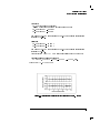
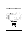
1. Connect the equipment as shown in Figure 3-1:
Turn o the AC power to the microwave amplier prior to connecting or
disconnecting the source module interface cable.
Figure 3-1. Millimeter-Wave Equipment Setup
2. Enter the proper multiplier value for the HP 8355X-series source
module that you are using into the synthesizer.
Perform the following procedure to select and enter the proper multiplier
value.
a. Press the 4
5 key.
b. Press the 4
5 key.
SHIFT
FREQ
3-4
Generating Signals with the Synthesizer
To Generate Millimeter Signals
c. Press the numeric key on the synthesizer numeric keypad that
corresponds to the proper multiplier value from the following table:
Source Module
Frequency Band
Model Number
Multiplier
Value
HP 83554A
26.5 - 40 GHz
2
HP 83555A
33 - 50 GHz
3
HP 83556A
40 - 60 GHz
3
HP 83557A
50 - 75 GHz
4
HP 83558A
75 - 110 GHz
6
d. Terminate the multiplier value entry by pressing the 4
5
Hz
(ENTER) key.
3. Set the frequency for the desired output signal.
The synthesizer frequency display will show the frequency at the output of
the millimeter source module, not the synthesizer RF OUTPUT connector.
For example, if you want to generate a 30 GHz CW only signal, perform
the following steps:
5 key.
a. Press the 4
b. Type 4 5 on the numeric keypad.
c. Press the 4 5 key to terminate the entry.
5 key to
4. If the RF output is currently turned o, press the 4
FREQ
30
GHz
RF ON/OFF
turn it on.
If the RF output is o, the word OFF appears in the power level portion of
the right-most display.
5 key to enable internal leveling.
5. Press the 4
6. Set the approximate desired RF output power at the output of the
INT LEVEL
millimeter source module using the display on the microwave amplier.
5 and rotate
For example, to set the level to 0 dBm, press 4
the synthesizer knob until \0 dBm" is shown on the microwave amplier
display.
POWER LEVEL
7. Press the 4
5
EXT DIODE
key.
3-5
Generating Signals with the Synthesizer
To Generate Millimeter Signals
8. Set the RF output power level desired at the output of the millimeter
source module using the display on the microwave amplier.
The display on the microwave amplier shows the power level at the
output of the source module to within 62 dB. You should use the display
on the microwave amplier, not the synthesizer, when adjusting the RF
output power. For example, to set the output power level to 0 dBm, press
5 key and rotate the knob until \0 dBm" is shown on the
the 4
microwave amplier display.
POWER LEVEL
NOTE
)
(
The knob resolution can be changed using the 4 5 and 4 5 keys. However, the multiplied signal
frequency resolution is further limited due to the multiplier value used. For example, if the multiplier
value is set to 3 and the synthesizer baseband resolution is 1 kHz, the resulting resolution is 3 kHz.
3-6
To Use External Diode Detector Leveling
External diode detector leveling is useful when you desire leveled RF output
power from the synthesizer at a point other than the RF OUTPUT connector.
External diode detector leveling uses the following external equipment.
Equipment
Requirements
Diode Detector
Must be specied for use at the desired synthesizer output
frequency. Must produce greater than 1 mv of ALC voltage
for the power levels present at the sampling point. Detector
can be either positive or negative.
Power Splitter
Must be specied for use at the desired synthesizer output
frequency.
or
Directional Coupler
Power Meter
None.
(optional)
Power Sensor
(optional)
Cables and Adapters
Must be capable of measuring power at the frequency and
level present at the sampling point in the leveling loop.
You must supply the cables and adapters necessary to
connect the equipment.
NOTE
The power meter and power sensor are not required, but are helpful when adjusting the synthesizer
output power for the desired power level at the output.
3-7
Generating Signals with the Synthesizer
To Use External Diode Detector Leveling
In addition, you must supply the cables and adapters necessary to connect
the equipment.
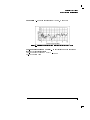
1. Connect the equipment as shown in Figure 3-2:
Figure 3-2. External Diode Detector Leveling Setup
2. Press the 4
EXT DIODE
5
key to enable external leveling.
NOTE
When the 4EXT DIODE5 key is pressed, the synthesizer enters the external diode detector leveling
mode. Power is then held at a constant level at the sampling point, regardless of gain changes in the
signal path between the synthesizer RF OUTPUT connector and the output.
3. Set the desired output signal frequency using the 4
5
FREQ
modulation.
4. If the RF output is currently turned o, press the 4
turn it on.
key and any
5
RF ON/OFF
key to
(If the RF output is o, the word OFF appears in the power level portion
of the right-most display.)
3-8
Generating Signals with the Synthesizer
To Use External Diode Detector Leveling
5. Adjust the synthesizer output power so that the desired power at the
output is attained.
For example, assume that you are using a power splitter and you want 05
dBm at the output of the splitter. In this case, you must set the power at
the output to 05 dBm. Perform the following procedure to set the power
at the output to 05 dBm.
a. Temporarily connect the power meter and sensor at the output.
5 key.
b. Press the 4
c. Rotate the knob until the power meter reads 05 dBm (disregard the
synthesizer power level reading).
d. Disconnect the power meter and sensor from the output and connect
the device under test (DUT).
POWER LEVEL
Notes
1. When the 4EXT DIODE5 key is pressed, the synthesizer output power might change. Therefore,
you might want to check the output power and readjust if necessary.
2. External diode detector leveling does not provide temperature compensation, thus, output level
recalibration might be required in environments that are not temperature stabilized.
3. External diode detector leveling does not provide proper compensation from square law to linear
regions of the detector. Therefore, power level changes may require output level recalibration.
3-9
Generating Signals with the Synthesizer
To Use External Diode Detector Leveling
Programming Command
The following command is related to external diode detector leveling.
POW:ALC:SOUR DIOD
Enables external diode detector leveling.
Related Tasks
To Use External Power Meter Leveling
3-10
To Use External Power Meter Leveling
External power meter leveling is useful when you desire leveled RF output
power from the synthesizer at a point other than the RF OUTPUT connector.
External power meter leveling requires the following external equipment.
Equipment
Requirements
Power Meter
Must have a recorder output and range hold capability.
Power Sensor
Must be capable of measuring power at the frequency and
level present at the sampling point in the leveling loop.
Power Splitter
Must be specied for use at the desired synthesizer output
frequency.
or
Directional Coupler
In addition, you must supply the cables and adapters necessary to connect
the equipment.
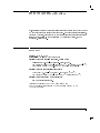
1. Connect the equipment as shown in Figure 3-3:
Figure 3-3. External Power Meter Leveling Setup
2. Press the 4
5 key to enable internal leveling.
3. Set the desired output signal frequency using the 4
INT LEVEL
5
FREQ
key.
3-11
Generating Signals with the Synthesizer
To Use External Power Meter Leveling
4. Set the desired output power level using the 4
5. If the RF output is currently turned o, press the 4
5
POWER LEVEL
key.
5 key to
RF ON/OFF
turn it on.
If the RF output is o, the word OFF appears in the power level portion
of the display.
6. Select auto range on the power meter.
7. Modify the synthesizer output power so that the power meter display
indicates the power desired at the sampling point.
For example, assume that you are using a directional coupler that has
a coupling factor of 22 dB and you want +5 dBm at the output of the
coupler. In this case, you must set the power at the sampling point (the
coupled output) to 017 dBm. Perform the following procedure to set the
power at the sampling point to 017 dBm.
5 key.
a. Press the 4
b. Rotate the knob on the synthesizer until the power level displayed on
the power meter is 017 dBm. Disregard the power level shown on the
synthesizer display.
POWER LEVEL
8. Select range hold on the power meter.
5 key on the synthesizer.
9. Press the 4
When the 4
5 key is pressed, the text RNG-HOLD,POWER
XXXdBm appears in the display, where XXX is the last range hold meter
value that was entered.
10. Enter the power shown on the power meter display into the
EXT METER
EXT METER
synthesizer using the numeric keypad.
The value entered into the synthesizer is called the range hold meter
value. For example, if the power meter currently reads 017 dBm,
perform the following procedure to enter 017 dBm into the synthesizer:
a. Type 40 5 on the synthesizer numeric keypad.
b. Terminate the range hold meter value entry by pressing the 4 5
(dBm) key.
17
GHz
3-12
Generating Signals with the Synthesizer
To Use External Power Meter Leveling
When the range hold meter value is terminated, the synthesizer enters the
external power meter leveling mode. Power is then held at a constant level at
the sampling point, regardless of gain changes in the signal path between the
synthesizer RF OUTPUT connector and the sampling point.
Programming Commands
The following commands are related to external power meter leveling.
POW:ALC:PMET reading
POW:ALC:SOUR PMET
Reads the initial power meter reading into the
synthesizer. The initial power meter reading is
dened by the \reading" parameter.
Enables external power meter leveling.
Related Tasks
To Use External Diode Detector Leveling
3-13
To Use the Level Correct Routine
When activated, the level correct function adjusts the synthesizer output
power (to compensate for losses or gains) to provide constant, leveled power
at output of the external signal path.
When the level correct routine is used, the synthesizer performs a calibration
process that corrects for external losses or power variations in an external
signal path. When the level correct routine is run, a power meter that
is under control of the synthesizer will measure power variations at the
output of the external signal path over a user-dened frequency range. The
synthesizer then reads back the power level data from the power meter
and creates a table of correction values for each frequency point (the level
correction table).
The level correction table resides in non-volatile memory and up to four
level correction tables can be stored for later use. If the power meter is in a
favorable range, the level correct routine takes approximately two minutes to
run.
NOTE
When using the level correct routine, the external path to the synthesizer must be linear (must have a
1 dB per 1 dB transfer function).
Using the level correct routine requires the following external equipment.
Equipment
3-14
Requirements
HP 437B, 438A, 70100A, or
SCPI compatible power meter
No substitute.
Power Sensor
Must be compatible with the power meter used. Must be
capable of measuring power at the frequencies and levels
present at the output of the signal path being leveled.
Generating Signals with the Synthesizer
To Use the Level Correct Routine
In addition, you must supply the cables and adapters necessary to connect
the equipment.
1. Connect the equipment as shown in Figure 3-4:
Figure 3-4. Level Correct Routine Equipment Setup
2. Set the address that the synthesizer will use to address the power
meter during the level correct routine.
For example, use the following procedure to set the power meter address
to 23.
5 key.
a. Press the 4
b. Type 4 5 on the synthesizer numeric keypad.
c. Press the 4 5 (ENTER) key. You will be prompted to enter the power
meter address.
d. Type 4 5 on the synthesizer numeric keypad.
e. Terminate the power meter address by pressing the 4 5 (ENTER) key.
SPCL
20
Hz
23
Hz
3. Choose the programming language that the synthesizer will use to
communicate with the power meter over the HP-IB.
For example, use the following procedure to choose HP 437B compatible
programming language.
a. Press the 4
5 key.
b. Type 4 5 on the synthesizer numeric keypad.
c. Press the 4 5 (ENTER) key.
SPCL
21
Hz
3-15
Generating Signals with the Synthesizer
To Use the Level Correct Routine
d. Press the 4*5 or 4+5 key until the display reads POWER METER IS
HP437B.
5 key.
4. Press the 4
5. Adjust the power level to a level near the center of the power sensor
POWER LEVEL
range.
6. Press the 4
5
SHIFT
key and then the 4
5
INT LEVEL
(LVL CR) key.
When 4
5, 4
5 (LVL CR) is pressed, the words COR START XXX
appear in the left-most display where XXX is the current level correct
start frequency.
SHIFT
INT LEVEL
7. Enter the desired level correct start frequency. If the start frequency
shown in the display is the desired start frequency, continue with step
8.
For example, use the following procedure to set the level correct start
frequency to 3.5 GHz.
a. Type 4 5 on the synthesizer numeric keypad.
b. Terminate the level correct start frequency by pressing the 4 5 key.
Note that the level correct start frequency remains on the display after
it is terminated so that it can be modied using the knob or 4*5, 4+5
keys if desired.
3.5
GHz
8. Press the 4
entry.
5
Hz
(ENTER) key to begin level correct stop frequency
When the 4 5 (ENTER) key is pressed, the words COR STOP XXX appear
in the left-most display where XXX is the current level correct stop
frequency.
Hz
9. Enter the desired level correct stop frequency. If the stop frequency
shown in the display is the desired stop frequency, continue with step
10.
For example, use the following procedure to set the level correct stop
frequency to 9.75 GHz.
a. Type 4 5 on the synthesizer numeric keypad.
b. Terminate the level correct stop frequency by pressing the 4 5 key.
9.75
GHz
3-16
Generating Signals with the Synthesizer
To Use the Level Correct Routine
Note that the level correct stop frequency remains on the display after
it is terminated so that it can be modied using the knob or 4*5, 4+5
keys if desired.
10. Press the 4 5 (ENTER) key to begin the number of points entry.
When the 4 5 (ENTER) key is pressed, the words SET NUMBER OF
POINTS XXX appear in the left-most display where XXX is the current
number of points. A maximum of 401 points can be entered.
11. Enter the desired number of points. If the number of points shown in
Hz
Hz
the display is the desired number of points, continue with step 12.
Note that the start frequency and stop frequency are included in the
number of points. Use the following procedure to set the number of
points to 100, for example.
a. Type 4 5 on the synthesizer numeric keypad.
b. Terminate the number of points entry by pressing the 4 5 (ENTER)
key.
Note that the number of points entry remains on the display after it is
terminated so that it can be modied using the knob or 4*5, 4+5 keys if
desired.
100
Hz
12. Press the 4 5 (ENTER) key.
When the 4 5 (ENTER) key is pressed, the words RUN CORRECTION?,
HIT ENTER appear in the left-most display
13. Press 4 5 (ENTER) to run the level correct routine.
The level correct routine can be aborted before it begins running by
pressing the 4
5 key. It can also be aborted any time while it is
5 key.
running by pressing the 4
As the level correct routine is running, the right-most display will be
blanked and the left-most display will show each frequency point and
measured power level as each measurement occurs. When the level
correct routine has nished running, the left-most display will blank
and the frequency and output power level will return to the right-most
display.
Hz
Hz
Hz
LOCAL
LOCAL
3-17
Generating Signals with the Synthesizer
To Use the Level Correct Routine
NOTE
As the routine is running, the synthesizer sends the power meter each frequency point so that the
correct calibration factor at each frequency can be used.
For best accuracy, the correct calibration factors for the power sensor being used should be entered
into the power meter prior to running the level correct routine.
14. When the level correct routine has nished running, press the 4
5
SHIFT
5 (LVL CR ON/OFF) key to enable the
key and then the 4
synthesizer to use the level correct data when determining the output
power level.
When the level correct data has been enabled, the LVL CR annunciator
POWER LEVEL
will be lit.
15. Disconnect the power meter and power sensor from the level correct
setup.
The output of the external signal path can now be connected to the
device under test.
The data stored in non-volatile memory will only be valid for the current
external signal path. If the external signal path is changed, the level
correct routine will have to be rerun.
NOTE
The table of level correct values should be stored in one of four level correction register locations for
later use.
3-18
Generating Signals with the Synthesizer
To Use the Level Correct Routine
To store the table of level correct values in a level correction register location,
perform the following procedure.
5 (SAVE CR) key.
5 key and then the 4
1. Press the 4
The display will show SAVE IN TABLE XXX where XXX is the current level
correction register number.
2. Enter the desired level correction register number.
For example, use the following procedure to choose level correction
register number 2.
a. Type 4 5 on the synthesizer numeric keypad.
b. Terminate the level correction register number entry by pressing the
4 5 (ENTER) key.
SHIFT
INT LEVEL
2
Hz
NOTE
Once the level correction register number entry has been terminated, the current table of level correct
values will write over any old level correct data stored at that register location.
Related Tasks
To Use Previously Stored Level Correct Data
3-19
To Use Previously Stored Level Correct Data
When the level correct routine is run, the synthesizer creates a table of
correction values for each frequency point in the table. Up to four level
correction tables can be stored in the synthesizer memory. If the current
signal path at the synthesizer output (the external signal path) is identical to
the external signal path on which a level correct routine had been previously
run, the level correction table can be recalled from memory and be used at a
later time.
1. Verify that the current external signal path is correct for the level
correct table you want to recall from memory and use.
The current external signal path must be identical to the external signal
path that was calibrated and stored in the level correct table that you wish
to recall. If the current external signal path is dierent, the data can cause
inaccurate output power levels at the output of the external signal path.
5 (RCL CR) key.
5 key and then the 4
2. Press the 4
The display will show RECALL FRM TABLE XXX where XXX is the last level
correction register number recalled.
3. Enter the level correction register number of the register that contains
SHIFT
EXT METER
the level correct data you want to use.
For example, use the following procedure to choose level correction
register number 2.
a. Type 4 5 on the synthesizer numeric keypad.
b. Terminate the level correction register number entry by pressing the
4 5 (ENTER) key.
2
Hz
5 (LVL CR ON/OFF) key
5 key and then the 4
to enable the synthesizer to use of level correct data when determining
the output power level.
When the use the level correct data has been enabled, the LVL CR
4. Press the 4
SHIFT
annunciator will be lit.
3-20
POWER LEVEL
Generating Signals with the Synthesizer
To Use Previously Stored Level Correct Data
Related Tasks
To Use the Level Correct Routine
3-21
If You Encounter a Problem
If you have a problem generating signals with the synthesizer, check the
following list of commonly encountered problems and troubleshooting
procedures.
If the problem involves data entry, check the section in Chapter 2 entitled, \If
You Encounter a Problem." If the problem that you encounter is not in the
following list or in Chapter 2, contact the nearest Hewlett-Packard oce for
assistance.
Annunciators Turned On
If the UNLVL LED annunciator is on:
Check the leveled power specication to make sure that you have not
exceeded the specication.
The maximum power specication is frequency dependent. Typically
less maximum power is available as the synthesizer output frequency is
increased.
If external diode detector leveling or external power meter leveling is being
used, ensure that the leveling loop is not opened.
If external diode detector leveling or external power meter leveling is
being used, ensure that the synthesizer output is not being forced into an
unleveled condition by the leveling circuitry.
If the circuit path before the sampling point has a lot of attenuation, the
synthesizer will have to source high power even though the required
power at the sampling point seems low. For example, if the circuit before
the sampling point has 23 dB of attenuation and the power required at
the sampling point is 5 dBm, the synthesizer will need to source 28 dBm,
which is more that its maximum specied power level.
3-22
Generating Signals with the Synthesizer
If the MSG LED annunciator is on:
If the synthesizer MSG annunciator is on, there is a problem with the
synthesizer. To determine the error and turn o the MSG annunciator, refer
to \To Read the Contents of the Error Queue" in Chapter 2 and the listing of
error messages in Chapter 8.
RF Output Problems
If there is no signal at the RF Output connector:
Check that the signal at the RF OUTPUT connector is turned on.
If the RF OUTPUT connector is turned o, the text OFF will be displayed in
place of dBm in the right-most display.
If the signal at the RF OUTPUT connector is turned o, press the
4
5 key once to turn it on.
RF ON/OFF
If the signal at the RF OUTPUT connector does not appear to be phase
locked to the external reference:
Check that the external reference is within synthesizer specications. Refer
to the Specication table in Chapter 4 for the external reference input
specications.
3-23
Generating Signals with the Synthesizer
4
Specications and Options
Specications and Options
This chapter contains listings of the synthesizer performance specications
and the mechanical, electrical, warranty, and documentation options that are
available.
Specications for each instrument appear under the instrument number,
further on in this chapter. The general specications given here apply equally
to the HP 83711A/12A and HP 83711B/12B.
4-2
HP 83711A/11B Specications
Specications describe the instrument's warranted performance over the 0 to
55 temperature range unless otherwise noted. Supplemental characteristics,
indicated by italics, are intended to provide information useful in estimating
instrument capability in your application by describing typical, but not
warranted, performance.
Frequency
Range: 1.0 to 20.0 GHz
Resolution: 1 kHz (1 Hz with Option 1E8)
Stability (with high stability timebase, Option 1E5):
Aging Rate: <1.5210 /day after 24-hour warm up.
-9
Temperature Eects: <1210-7 over 0 to 55 C, nominally <1.4210-9 / C
Line Voltage Eects: <5210-10 for 10% change in line voltage
Stability (without high stability timebase):
Aging Rate: <1.0210-8 /day after 72-hours at 25 C610 C
Temperature Eects: <5210-6 over 0 to 55 C referenced to 25 C
Stability (with external 10 MHz reference):
Same as external reference.
Frequency Switching Time: <50 ms to within 1 kHz
For <1 GHz steps, not across 10 GHz band switch point:
(HP 83711B only)
<35 ms
4-3
Specications and Options
HP 83711A/11B Specications
RF Output
Maximum Leveled Output Power (0 C to +35 C):
Frequency
Standard
with Option 1E1
1 20 GHz
+11 dBm
+10 dBm
0
Figure 4-1.
Typical Maximum Available Output Power from 1 to 20 GHz, at 25 C with Output Step
Attenuator (Option 1E1) Installed
Minimum Leveled Output Power (without Option 1E1):
0 dBm
Minimum Leveled Output Power (with Option 1E1):
0110 dBm (090 dBm on HP 83711A)
Display Resolution:
0.01 dB
4-4
Specications and Options
HP 83711A/11B Specications
Accuracy:
61.0 dB (over all power levels)
(0 dBm to specied maximum leveled output power)
62.0 dB (power 090 dBm)
62.5 dB (power < 090 dBm
The use of Type-N RF connectors above 18.0 GHz degrades specication
typically by 0.2 dB.
Flatness:
60.5 dB (power 090 dBm)
60.7 dB (power <090 dBm)
The use of Type-N RF connectors above 18.0 GHz degrades specication
typically by 0.2 dB.
Level Switching Time: <17 ms (without step attenuator range change)
Attenuator range changes occur at:
HP 83711B, HP 83712B 01 dBm, 011 dBm, 021 dBm, etc.)
Output SWR: <2.0 : 1 nominal
Figure 4-2. Typical Output Level Accuracy and Flatness at +10 and 085 dBm
4-5
Specications and Options
HP 83711A/11B Specications
Spectral Purity
SSB Phase Noise (dBc/Hz):
Table 4-1. Osets (HP 83711A only)
Carrier Freq.
2 GHz
10 GHz
18 GHz
100 Hz
066
069
063
1 kHz
074
075
070
10 kHz
091
079
073
100 kHz
0107
0101
099
Table 4-2. Osets (HP 83711B only)
Carrier Freq.
<2 GHz
2 GHz to <5 GHz
5 GHz to <10 GHz
1 GHz to
10 GHz to 20 GHz
100 Hz
073
070
069
065
1 kHz
083
078
078
073
10 kHz
092
083
082
076
100 kHz
0107
0100
0100
0100
Figure 4-3.
Typical single-sideband phase noise at 1 GHz, 10 GHz and 20 GHz, 25 C, CW mode. Osets less
than 100 Hz require the high stability timebase, Option 1E5.
4-6
Specications and Options
HP 83711A/11B Specications
Harmonics: <050 dBc at output levels <+6 dBm, 1 to 20 GHz
Figure 4-4. Typical 2nd Harmonic Levels Measured at Output Power of +6 dBm
Non-Harmonic Spurious (3 kHz): <060 dBc (includes power supply and
frequency synthesis spurious)
Non-Harmonic Spurious (<3 kHz):
Sub-Harmonics: None
< 050 dBc
4-7
Specications and Options
HP 83711A/11B Specications
Residual FM:
At 1 GHz, <15 Hz in 50 Hz015 kHz bandwidth.
Figure 4-5.
Typical Residual FM Measured in 50 Hz - 15 kHz Bandwidth, CW Mode, with High Stability
Timebase (Option 1E5)
AM Noise Floor: (at 0 dBm and osets greater than 5 MHz from carrier)
<0150 dBm/Hz
4-8
HP 83712A/12B Specications
Specications describe the instrument's warranted performance over the 0 to
55 temperature range unless otherwise noted. Supplemental characteristics,
indicated by italics, are intended to provide information useful in estimating
instrument capability in your application by describing typical, but not
warranted, performance.
Frequency
Range: 0.01 to 20.0 GHz
Resolution: 1 kHz (1 Hz with Option 1E8)
Stability (with high stability timebase, Option 1E5):
Aging Rate: <1.5210 /day after 24-hour warm up.
-9
Temperature Eects: <1210-7 over 0 to 55 C, nominally <1.4210-9 / C
Line Voltage Eects: <5210-10 for 10% change in line voltage
Stability (without high stability timebase):
Aging Rate: <1.0210-8 /day after 72-hours at 25 C610 C
Temperature Eects: <5210-6 over 0 to 55 C referenced to 25 C
Stability (with external 10 MHz reference):
Same as external reference.
Frequency Switching Time: <50 ms to within 1 kHz
For <1 GHz steps, not across 10 GHz band switch point:
(HP 83712B only)
<35 ms
4-9
Specications and Options
HP 83712A/12B Specications
RF Output
Maximum Leveled Output Power (0 C to +35 C):
Frequency
Standard
with Option 1E1
0.01 1 GHz
1 20 GHz
+13 dBm
+11 dBm
+13 dBm
+10 dBm
0
0
Figure 4-6.
Typical Maximum Available Output Power from 1 to 20 GHz, at 25 C with Output Step
Attenuator (Option 1E1) Installed
4-10
Specications and Options
HP 83712A/12B Specications
Figure 4-7. Typical Maximum Available Output Power from 0.01 to 1 GHz at 25 C.
Minimum Leveled Output Power (without Option 1E1): 0 dBm
Minimum Leveled Output Power (with Option 1E1): 0110 dBm
(090 dBm for HP 83712A)
Display Resolution: 0.01 dB
Accuracy: (0 dBm to specied maximum leveled output power)
10 MHz to 50 MHz: 61.3 dB
50 MHz to 20 GHz: 61.0 dB
Accuracy: (over all power levels)
10 MHz to 50 MHz: 62.3 dB (power 090 dBm)
50 MHz to 20 GHz: 62.0 dB (power 090 dBm)
10 MHz to 20 GHz: 62.5 dB (power <090 dBm)
The use of Type-N RF connectors above 18.0 GHz degrades specication
typically by 0.2 dB.
Flatness:
60.5 dB (power 090 dBm)
60.7 dB (power <090 dBm)
4-11
Specications and Options
HP 83712A/12B Specications
The use of Type-N RF connectors above 18.0 GHz degrades specication
typically by 0.2 dB.
Level Switching Time: <17 ms (without step attenuator range change.
Attenuator range changes occur at 01 dBm, 011 dBm, 021 dBm, etc.)
Output SWR: <2.0 : 1 nominal
Figure 4-8. Typical Output Level Accuracy and Flatness at +10 and 085 dBm
4-12
Specications and Options
HP 83712A/12B Specications
Spectral Purity
SSB Phase Noise (dBc/Hz):
Table 4-3. Osets (HP 83712A only)
Carrier Freq.
500 MHz
2 GHz
10 GHz
18 GHz
100 Hz
070
066
069
069
1 kHz
086
074
075
070
10 kHz
0103
091
079
073
100 kHz
0119
0107
0101
099
Table 4-4. Osets (HP 83712B only)
Carrier Freq.
<1 GHz
1 GHz to <2 GHz
2 GHz to <5 GHz
5 GHz to <10 GHz
500 MHz to
10 GHz to 20 GHz
100 Hz
078
073
070
069
065
1 kHz
092
083
078
078
073
10 kHz
0103
092
083
082
076
100 kHz
0115
0107
0100
0100
0100
Phase noise decreases 6 dB/octave below 500 MHz and reaches a oor of
0140 dBc/Hz.
4-13
Specications and Options
HP 83712A/12B Specications
Figure 4-9.
Typical single-sideband phase noise at 50 MHz, 1 GHz, 10 GHz and 20 GHz, 25 C, CW mode.
Osets less than 100 Hz require the high stability timebase, Option 1E5.
Harmonics: <055 dBc at output levels <+6 dBm, 0.01 to 1 GHz
Harmonics: <050 dBc at output levels <+6 dBm, 1 to 20 GHz
4-14
Specications and Options
HP 83712A/12B Specications
Figure 4-10. Typical 2nd Harmonic Levels Measured at Output Power of +6 dBm
Non-Harmonic Spurious (3 kHz):
<060 dBc (includes power supply and frequency synthesis spurious)
Non-Harmonic Spurious (<3 kHz):
< 050 dBc
Sub-Harmonics: None
4-15
Specications and Options
HP 83712A/12B Specications
Residual FM:
At 1 GHz, <15 Hz in 50 Hz015 kHz bandwidth. Residual FM decreases 6 dB
per octave below 1 GHz.
Figure 4-11.
Typical Residual FM Measured in 50 Hz - 15 kHz Bandwidth, CW mode, with High Stability
Timebase (Option 1E5)
AM Noise Floor: (at 0 dBm and osets greater than 5 MHz from carrier)
<0150 dBm/Hz, 1020 GHz.
<0140 dBm/Hz, 0.0101 GHz.
4-16
Specications and Options
HP 83712A/12B Specications
General
Programming
The HP 83711A/12A and HP 83711B/12B are fully compatible with
the Standard Commands for Programmable Instruments (SCPI). SCPI
programming complies with IEEE 488.2-1987. In addition, these synthesizers
will emulate most applicable HP 8673 commands, providing general
compatibility with ATE systems which include HP 8673 Series signal
generators. Refer to the HP 8673 compatibility chapter in the Programming
Guide for specic information. Please consult your HP sales representative for
details.
Environmental
Operating Temperature Range: 0 to 55 C (for indoor use).
Altitude: Up to 15,000 feet (4,572 meters).
Relative Humidity: 80% for temperatures up to 31 C decreasing linearly to
50% relative humidity at 40 C.
EMC: Complies with CISPR Publication 11/1990, Class A, Group 1 and
MIL-STD-461C, Part 2, Methods CE03 (NB full limits, BB 10 dB relaxation 150
kHz to 500 kHz, full limits elsewhere); CS01; CS02; RE02 (Curve 2 +10 dB);
RS03 (1 V/m, 15 kHz to 1 GHz).
This product is designed for use in INSTALLATION CATEGORY II and
POLLUTION DEGREE 2, per IEC 1010 and 664 respectively.
Acoustic Noise Emission (Geraeuschemission)
LpA <70 dB(A) per ISO 3744 (LpA <70 dB(A) nach DIN 45635 pt. 1)
LpA Operator position: 44.6 dB, based upon type test per ISO 6081. (LpA
am Arbeitsplatz: 44.6 dB, typpruefungsergebnis nach DIN 45635 pt. 19)
LpA Bystander position: 38.4 dB, based upon type test per ISO 6081. (LpA
ktiver Arbeitsplatz: 38.4 dB, typpruefungsergebnis nach DIN 45635 pt. 19)
4-17
Specications and Options
HP 83712A/12B Specications
Power Requirements
Power: 90-132V, 48-440 Hz. 198-264V, 48-66 Hz.
260 VA maximum.
Physical Dimensions
Net Weight: < 16 kg (35 lb)
Shipping: < 23 kg (49 lb)
Size: 498 mm D 2 426 mm W 2 133 mm H (19.6"216.8"25.2")
Transit case available by ordering HP Part Number 9211-2655.
Front Panel Connectors
RF OUTPUT
The standard front panel RF OUTPUT connector is a Type-N precision
connector. When Option 1E9 is installed, this front panel connector is a 3.5
mm precision connector. The nominal source impedance is 50
.
ALC IN
This front panel BNC connector allows the synthesizer to be externally
leveled. It is used with external power meter leveling or external diode
leveling. The leveling signal at this input must be in the 61V range. The
nominal input impedance is 150 k
. The damage level is +12 V or 012 V.
4-18
Specications and Options
HP 83712A/12B Specications
Rear Panel Connectors
10 MHz Input
Accepts a 10 MHz 6 100 Hz, 0 to +10 dBm, external reference signal for
operation from an external high stability timebase. Nominal input impedance
is 50
.
10 MHz Output
Outputs the 10 MHz reference signal, nominally +3 dBm, for use as an
external reference signal. Nominal source impedance is 50
.
0.5V/GHz Output
Supplies a voltage proportional to output frequency for use with mm-wave
frequency multipliers, including the HP 83550 Series Millimeter Wave Source
Modules.
4-19
Options
There are several electrical, mechanical, warranty, and documentation
options available for the CW Generator.
Electrical Options
There are four electrical options available for the CW Generator. These
options are as follows:
Option 1E1 - Add Output
Step Attenuator
If Option 1E1 is ordered, an internal step attenuator is included before the
RF OUTPUT connector. The step attenuator has a range of 0 to 110 dB
(90 dB for 83711A/83712A) in 10 dB steps (0|110 dB for 11B/12B). The
correct amount of attenuation is selected automatically by the CW Generator
dependent on the output power level selected. If this option is installed,
you can select whether or not the step attenuator will automatically switch.
This function is useful during certain applications, such as when external
automatic level control is used. <idxadd high stability timebase - option 1E5j
Option 1E5 - Add High
Stability Timebase
If Option 1E5 is ordered, the CW Generator is shipped with a 10 MHz
temperature controlled crystal reference oscillator for increased frequency
accuracy and stability. If Option 1E5 is installed, the CW Generator must be
connected to AC mains power to keep the reference oscillator at operating
temperature. If the reference oscillator has not been connected to mains
power (the oven is cold), the CW Generator requires 30 minutes to warm up.
Option 1E8 - 1 Hz
Frequency Resolution
Consult your HP sales representative for details on availability and retrot
information.
4-20
Specications and Options
Options
Option 1E9 - 3.5 mm RF
Output Connector
If Option 1E9 is ordered, the RF OUTPUT connector is a male APC-3.5
precision connector in place of the standard female Type-N connector.
Mechanical Options
There are three mechanical options available for the synthesizer. If these
options were not ordered with the original shipment, a Handle Kit (part
number 5062-3989) is included. If a mechanical option is desired later,
they can be ordered from the nearest Hewlett-Packard oce using the part
numbers included in each of the following paragraphs. These options are as
follows:
Option 1CM - Rack Mount
Kit
The synthesizer can be mounted to an instrument rack using the rack mount
kit. The Rack Mount Kit part number is 5062-3977.
Option 1CP - Rack Mount
and Handle Kit
The synthesizer can be mounted to an instrument rack using the rack ange
kit.
In addition, ease of handling is increased when the synthesizer is not rack
mounted by using the front panel handles. The Rack Mount and Handle Kit
part number is 5062-3983.
Option 1CR - Rack Slide
Kit
This kit is useful when the synthesizer is rack mounted. Access to internal
circuits and components or the rear panel is possible without removing the
synthesizer from the rack. The Rack Slide Kit part number is 1494-0059. If
a non-HP rack enclosure is used, rack adapters can be ordered to allow the
slide kit to be used with the non-HP rack. The part number for metric rack
adapters is 1494-0023 and the part number for standard inch rack adapters is
1494-0061.
4-21
Specications and Options
Options
Warranty Options
There are two warranty options available for the synthesizer. These options
are as follows:
Option W30 - Two
Additional Years
Return-to-HP Service
This option extends the benets of factory warranty to provide a total of 3
years of customer return repair service.
Option W32 - Three Year
Return-to-HP Calibration
Service
This option provides 3 years of HP calibration service at HP customer service
centers.
Documentation Options
Option OB0 - Delete
Operating Documentation
There are two documentation options available for the synthesizer. If the
documentation was not ordered with the original shipment and is now
desired, it can be ordered from the nearest Hewlett-Packard oce using the
part numbers included in each of the following paragraphs.
These options are as follows:
If Option OB0 is ordered, the shipment deletes copies of the HP 83711A/12A
and HP 83711B/12B Synthesized CW Generators User's Guide, the HP
83711A/12A and HP 83711B/12B Synthesized CW Generators Programming
Guide, the HP 83711A/12A and HP 83711B/12B Synthesized CW
Generators Quick Start Guide, and the HP 83711A/12A, HP 83711B/12B,
HP 83731A/32A, and HP 83731B/32B Synthesized CW Generators
Calibration Guide.
4-22
Specications and Options
Option OB1 - Extra
Operating Documentation
If Option OB1 is ordered, the shipment includes an extra copy of the
HP 83711A/12A and HP 83711B/12B Synthesized CW Generators User's
Guide, the HP 83711A/12A and HP 83711B/12B Synthesized CW Generators
Programming Guide, HP 83711A/12A and HP 83711B/12B Synthesized CW
Generators Quick Start Guide, and the HP 83711A/12A, HP 83711B/12B,
HP 83731A/32A, and HP 83731B/32B Synthesized CW Generators
Calibration Guide.
Option OBV Component-Level
Information Packet (CLIP)
If Option OBV is ordered, the shipment includes a copy of the
HP 83711A/12A, HP 83711B12B, HP 83731A/32A, and HP 83731B/32B
Synthesized CW Generators Component-Level Information Packet.
Option OBW - Service
Documentation
If Option OBW is ordered, the shipment includes a copy of the
HP 83711A/12A and HP 83711B/12B Synthesized CW Generators Service
Guide.
Option OBX Component-Level
Information Packet
(CLIP)/Service
Documentation
If Option OBX is ordered, the shipment includes a copy of the
HP 83711A/12A, HP 83711B/12B, HP 83731A/32A, and HP 83731B/32B
Synthesized CW Generators Component-Level Information Packet and a copy
of the HP 83711A/12A and 83711B/12B Synthesized CW Generators Service
Guide.
4-23
Specications and Options
5
Front/Rear Panel
Front/Rear Panel
This chapter contains detailed information on various aspects of the
synthesizer front and rear panel. Information on the synthesizer display,
front panel connectors, power cable, etc., can be found in this chapter.
5-2
Annunciators
The HP 83711A/12A and 83711B/12B front panel display contains
annunciators that show the status of several of the synthesizer functions and
settings.
Figure 5-1. Synthesizer Display Annunciators
All annunciators except the UNLOCK, UNLVL, and MSG annunciators
are contained on the uorescent display. A description of each of the
annunciators follows.
INT (ALC)
This annunciator indicates that internal power leveling is
selected.
DIODE (ALC) This annunciator indicates that external diode power
leveling is selected.
MTR (ALC)
This annunciator indicates that external power meter
leveling is selected.
MULT
This annunciator indicates that the frequency multiplier
function is active.
EXT REF
This annunciator indicates that an external time base is
currently being used.
5-3
Front/Rear Panel
Annunciators
SPCL
LVL CR
RMT
LSN
TLK
SRQ
UNLOCK
UNLVL
MSG
5-4
This annunciator indicates that one or more special
functions are enabled.
This annunciator indicates that the synthesizer output is
currently being leveled using stored level correction data.
This annunciator indicates that the instrument is in the
HP-IB remote state, that is, the instrument is under control
of an external HP-IB controller.
This annunciator indicates that the instrument is addressed
to listen (accept data or commands).
This annunciator indicates that the instrument is addressed
to talk (output data).
This annunciator indicates that the instrument is generating
a service request to the external controller.
This LED annunciator indicates that one or more of the
synthesizer frequency control circuits is not phase locked.
This LED annunciator indicates that the synthesizer output
power is unleveled. When the UNLVL annunciator is lit, the
power level shown in the display might be incorrect.
This LED annunciator indicates that uncleared error
messages are in the synthesizer front panel error queue.
Front/Rear Panel
Annunciators
See Also
Connectors
Display
4EXT
4EXT
4INT
DIODE
5
5
METER
5
LEVEL
4MSG5
MULTIPLIER
4SPCL5
5-5
Connectors
Figure 5-2. Synthesizer Connectors - Front Panel
Figure 5-3. Synthesizer Connectors - Rear Panel
5-6
Front/Rear Panel
Connectors
Coaxial Connectors
0.5 V/GHz OUT This rear panel BNC connector can be used as one of the
inputs to a recorder. It produces a DC voltage output that
varies linearly with the frequency currently at the RF
OUTPUT connector. For example, if the current frequency
setting is 5.5 GHz, the voltage at this connector would be
2.75 V. The nominal source impedance is 250
.
10 MHz IN
This rear panel BNC connector accepts a 10 MHz, 0 to +10
dBm reference signal for operation referenced to an external
time base. The nominal input impedance of this input is
50
. This connector detects when a valid reference signal is
connected to it and automatically switches from internal to
external reference operation.
10 MHz OUT
This rear panel BNC connector provides a 3 dBm 63 dB, 10
MHz signal derived from the internal frequency standard of
the synthesizer. The nominal source impedance is 50
.
ALC IN
This front panel BNC connector allows the synthesizer to be
externally leveled. It is used with external power meter
leveling or external diode leveling. The leveling signal at
this input must be in the 61V range. The nominal input
impedance is 150 k
. The damage level is +12 V or 012
V.
RF OUTPUT
The standard front panel RF OUTPUT connector is a Type-N
precision connector. When Option 1E9 is installed, this
front panel connector is a 3.5 mm precision connector. The
nominal source impedance is 50
.
When making connections to this connector, carefully align
the center conductor elements, then rotate the knurled
barrel while mating components remain still. Tighten the
barrel until rm contact is made.
Take care when working with this connector. If the
connector is mechanically degraded in any way, high
frequency losses can occur. Refer to application note 326,
Coaxial Systems - Principles of Microwave Connector Care
(HP part number 5954-1566) for more information.
5-7
Front/Rear Panel
Connectors
HP-IB Connector
This connector allows the synthesizer to be connected to other instruments
or devices on the interface bus. Details of this cable are shown in Figure 5-4.
HP part numbers for various HP-IB cables that are available are shown in the
table following the gure.
Figure 5-4. HP-IB Connector and Cable
Table 5-1. HP-IB Interface Cables Available
HP-IB Cable
Length
Part Number
5-8
HP 10833A
1 m (3.3 ft)
HP 10833B
2 m (6.6 ft)
HP 10833C
4 m (13.2 ft)
HP 10833D
0.5 m (1.6 ft)
Front/Rear Panel
Connectors
As many as 14 HP-IB instruments can be connected to the synthesizer (15
total instruments in the system). The cables can be interconnected in a star
pattern (one central instrument with the HP-IB cables emanating from that
instrument like spokes on a wheel), or in a linear pattern (like boxcars on a
train), or a combination of the two. There are certain restrictions that must
be followed when interconnecting instruments. These restrictions are as
follows:
Each instrument must have a unique HP-IB address, ranging from 0 to 30
(decimal). Refer to \To Set the HP-IB Address" in Chapter 2 for information
on setting the synthesizer HP-IB address.
In a two-instrument system that uses just one HP-IB cable, the cable length
must not exceed 4 meters (13.2 ft).
When more than two instruments are connected on the bus, the cable
length to each instrument must not exceed two meters (6.6 ft).
The total cable length between all instruments must not exceed 20 meters
(65 ft).
Hewlett-Packard manufactures HP-IB extender instruments (Models HP
37201A and HP 37204A/B) that overcome the range limitations imposed by
the cabling rules. These extenders allow twin pair cable operation up to 1 km
(3,280 ft), and telephone modem operation over any distance. HP sales and
service oces can provide additional information on the HP-IB extenders.
5-9
Front/Rear Panel
Connectors
The codes in the following list describe the HP-IB interface capabilities of the
synthesizer using IEEE Std.488.1 compatibility codes (HP-IB, GP-IB, IEEE-488,
and IEC-625 are all electrically equivalent). Briey, the mnemonics translate
as follows:
SH1
Source Handshake, complete capability.
AH1
Acceptor Handshake, complete capability.
T5
Talker; capable of basic talker, serial poll, and unaddress if
MLA.
TE0
Talker, Extended address; no capability.
L3
Listener; capable of basic listener and unaddress if MTA.
LE0
Listener, Extended address; no capability.
SR1
Service Request, complete capability.
RL1
Remote Local, complete capability.
PP0
Parallel Poll, no capability.
DC1
Device Clear, complete capability.
DT0
Device Trigger, no capability.
C1
Controller capability, system controller.
E2
Electrical specication indicating tri-state outputs.
These codes are described completely in the IEEE Standard 488 (1978),
IEEE Standard Digital Interface for Programmable Instrumentation or the
identical ANSI Standard MC1.1.
5-10
Display
The HP 83711A/12A and 83711B/12B front panel display contains an area for
displaying the current operating parameters of the synthesizer. Front panel
annunciators show the status of several of the synthesizer functions and
settings.
Figure 5-5. Synthesizer Display
A description of the display follows:
Annunciators The front panel annunciators show the status of several of
the synthesizer functions and settings. An annunciator
that is in uorescent display is not visible if its associated
function is not active or selected. For example, if diode
detector leveling is currently selected, the DIODE
annunciator will be lit, otherwise, it will not be visible. The
uorescent display annunciators are INT (ALC), DIODE
(ALC), MTR (ALC), MULT, EXT REF, SPCL, LVL CR, RMT,
LSN, TLK, and SRQ.
The three front panel LED annunciators (UNLOCK, UNLVL,
and MSG) will be lit to warn you that an associated
condition exists. (For example, if error messages are in
the error queue, the MSG annunciator will be lit.) An
5-11
Front/Rear Panel
Display
Display
explanation of each annunciator can be found in the
\Annunciators" entry in this section of the manual.
The carrier display is the uorescent display that is on the
right side of the front panel. The primary purpose of this
display is to indicate the current setting of the synthesizer
output frequency and power level.When parameter entry is
initiated, the information in this display will be temporarily
replaced with a parameter entry display. Pressing 4 5
(ENTER) returns the frequency and power level information
5 key is pressed,
to the display. As an example, if the 4
the text RECALL STATE FROM REG 0 appears in the display.
If a cursor ( 9 ) appears over one of the digits in the display,
this digit will be increased or decreased as the knob is
rotated. Note that the cursor indicates that particular
parameter is active. The cursor can be moved left or right
by pressing the 4(5 or 4)5 keys.
Hz
RECALL
NOTE
When operating the synthesizer in a secure environment, the display can be blanked so that the
synthesizer parameters and status cannot be viewed. For more information, refer to the \Clear Display"
entry in Chapter 7 of this manual.
See Also
(5
)5
4
4
Annunciators
CLEAR DISPLAY
DISPlay[:WINDow][:STATe]
Knob
5-12
Knob
The knob is used to increase or decrease parameter values. A cursor
( 9 ) over a digit in the display indicates that digit will be increased or
decreased in steps of one as the knob is rotated.
Clockwise rotation of the knob increases the display digit under the cursor
and counterclockwise rotation decreases it. Pressing the 4(5 key moves the
display cursor to the left and pressing the 4)5 key moves the cursor to the
right. As the knob is rotated, the display will carry over to the adjacent digit.
For example, if the display reads 9.000000000 GHz with the cursor over the
\9" digit, clockwise rotation of the knob will cause the displayed frequency
to change to 10.000000000 GHz. The cursor will remain over the rst digit
before the decimal point (the \0" in \10").
If 4
5 (ENTRY OFF), 4)5) has been enabled, the cursor will disappear
from the display and rotating the knob will have no aect on the synthesizer
parameters.
SHIFT
Equivalent SCPI Command
There is no equivalent SCPI command for knob rotation, however, the
\SYST:KEY 61" command simulates clockwise knob rotation and the
\SYST:KEY 62" command simulates counterclockwise knob rotation.
5-13
Front/Rear Panel
Knob
See Also
(5
)5
4
4
ENTRY OFF
SYSTem:KEY
5-14
POWER Switch
The POWER switch (LINE on HP 83711A/B) turns power to the synthesizer to
either on ( ) or standby ( ).
The POWER switch (LINE on HP 83711A/B) is located at the bottom left
corner of the front panel and is a rocker-type switch. Pressing the symbol
turns the synthesizer on and pressing the symbol turns it to standby.
When set to standby, most of the synthesizer circuitry is powered o,
however, power to the internal timebase is not disconnected.
WARNING
CAUTION
Before turning the synthesizer on, make sure that it is grounded
through the protective conductor of the power cable to a mains power
receptacle provided with protective earth contact. Any interruption of
the protective grounding conductor inside or outside of the synthesizer
or disconnection of the protective earth terminal can result in personal
injury.
Before turning the synthesizer on, set the line voltage selector to the voltage
of the power source. Failure to do this can cause instrument damage when
the power cable is plugged in. For information on setting the line voltage
selector, refer to \To Install the Synthesizer" in Chapter 1 of this manual.
See Also
To Install the Synthesizer
Power Cables
5-15
Power Cables
The line power cable is supplied in one of several congurations, depending
on the destination of the original shipment.
Each instrument is equipped with a three-wire power cable. When connected
to an appropriate AC power receptacle, this cable grounds the instrument
chassis. The type of power cable shipped with each instrument depends on
the country of destination. See Figure 5-6, \Power Cable and Line (Mains)
Plug Part Numbers," for the part numbers of these power cables. Cables
are available in dierent lengths and some with right-angle plugs to the
instrument. Check with your nearest Hewlett-Packard service center for
descriptions and part numbers for these cables.
5-16
Front/Rear Panel
Figure 5-6. Power Cable and Line (Mains) Plug Part Numbers
5-17
Front/Rear Panel
6
Keys/Shifted Functions
Keys/Shifted Functions
This chapter contains detailed information on the various keys and shifted
functions found on the synthesizer front panel. Key names are printed on the
keycap and represent the primary function of the key. The shifted function
names appear above certain keys on the synthesizer front panel. Shifted
functions are always accessed by pressing the 4
5 key and then the key
below the shifted function name. If no text appears above a given key, that
key has no shifted function associated with it.
SHIFT
6-2
)
The 4)5 key moves the cursor ( 9 ) that appears over one of the digits in the
display to the right one digit each time it is pressed.
The digit that is currently under the cursor will be increased or decreased in
steps of one as the knob is rotated. Clockwise rotation of the knob increases
the digit under the cursor and counterclockwise rotation decreases it. If
pressing the 4)5key moves the cursor too far to the right, pressing the 4(5
key will move the cursor back to the left.
NOTE
*
+
The digit under the cursor is aected only by the knob, not the 4 5 and 4 5 keys.
If 4
5 (ENTRY OFF), 4)5) has been enabled, the cursor will disappear
from the display and rotating the knob will have no aect on the parameter.
Note that the cursor indicates that particular parameter is active. For
example, if the cursor appears over any digit in the frequency display, the
frequency parameter is the active parameter.
If an arrow key is pressed that moves the cursor to a position that is o the
display, another cursor will appear next to the original cursor to indicate
that the actual cursor position is o the display. For example, if a frequency
multiplier of six is entered into the synthesizer, the maximum frequency
entry that can be made is 120 GHz (20 GHz26). The display, however, only
has room to display two digits to the left of the decimal point. If you were to
attempt to position the cursor three digits to the left of the decimal point, the
double cursor would appear, indicating that the actual cursor position is o
the display.
SHIFT
6-3
Keys/Shifted Functions
)
Equivalent SCPI Command
There is no equivalent SCPI command for the 4)5 key, however, sending the
\SYST:KEY 45" command is eectively the same as pressing the 4)5 key.
See Also
(5
4
ENTRY OFF
Knob
SYSTem:KEY
6-4
(
The 4(5 key moves the cursor ( 9 ) that appears over one of the digits in the
display to the left one digit each time it is pressed.
The digit that is currently under the cursor will be increased or decreased in
steps of one as the knob is rotated. Clockwise rotation of the knob increases
the digit under the cursor and counterclockwise rotation decreases it. If
pressing the 4(5 key moves the cursor too far to the left, pressing the 4)5
key will move the cursor back to the right.
NOTE
*
+
The digit under the cursor is aected only by the knob, not the 4 5 and 4 5 keys.
If 4
5, 4)5 (ENTRY OFF) has been enabled, the cursor will disappear from
the display and rotating the knob will have no aect on the parameter. Note
that the cursor indicates that particular parameter is active. For example, if
the cursor appears over any digit in the frequency display, the frequency
parameter is the active parameter.
If an arrow key is pressed that moves the cursor to a position that is o the
display, another cursor will appear next to the original cursor to indicate
that the actual cursor position is o the display. For example, if a frequency
multiplier of six is entered into the synthesizer, the maximum frequency
entry that can be made is 120 GHz (20 GHz26). The display, however, only
has room to display two digits to the left of the decimal point. If you were to
attempt to position the cursor three digits to the left of the decimal point, the
double cursor would appear, indicating that the actual cursor position is o
the display.
SHIFT
6-5
Keys/Shifted Functions
(
Equivalent SCPI Command
There is no equivalent SCPI command for the 4(5 key, however, sending the
\SYST:KEY 37" command is eectively the same as pressing the 4(5 key.
See Also
)5
4
ENTRY OFF
Knob
SYSTem:KEY
6-6
*
The 4*5 key allows you to incrementally add to the current value of a
parameter.
Pressing the 4*5 key will increase the currently active parameter by the
5 key. A parameter can be made
increment value set with the 4
active by pressing its associated function key. For example, pressing
the 4
5 key will make frequency the active parameter, pressing the
5 key will make output power level the active parameter, etc. If
4
5, 4)5 (ENTRY OFF) function
no parameter is currently active, or the 4
has been enabled, pressing the 4*5 key will have no eect.
If the 4*5 key is pressed and held down, the key will auto-repeat, that is, the
active parameter will automatically increase rapidly in increment value steps.
STEP SIZE
FREQ
POWER LEVEL
SHIFT
Equivalent SCPI Commands
There is no equivalent SCPI command for the 4*5 key, however, the various
SCPI commands that send numeric parameter data include an \UP"
parameter option. Sending the \UP" parameter in place of the numeric
parameter is eectively the same as pressing the 4*5 key. For example, if you
want to increase the output frequency by its current increment value, send
the following command:
OUTPUT 719; "FREQ UP"
6-7
Keys/Shifted Functions
*
See Also
+
4 5
ENTRY OFF
4STEP
6-8
5
SIZE
+
The 4+5 key allows you to incrementally subtract from the current value of a
parameter.
Pressing the 4+5 key will decrease the currently active parameter by the
5 key. A parameter can be made
increment value set with the 4
active by pressing its associated function key. For example, pressing
the 4
5 key will make frequency the active parameter, pressing the
5 key will make output power level the active parameter, etc. If
4
5, 4)5 (ENTRY OFF) function
no parameter is currently active, or the 4
has been enabled, pressing the 4+5 key will have no eect.
If the 4+5 key is pressed and held down, the key will auto-repeat, that is, the
active parameter will automatically decrease rapidly in increment value steps.
STEP SIZE
FREQ
POWER LEVEL
SHIFT
Equivalent SCPI Commands
There is no equivalent SCPI command for the 4+5 key, however, the various
SCPI commands that send numeric parameter data include a \DOWN"
parameter option. Sending the \DOWN" parameter in place of the numeric
parameter is eectively the same as pressing the 4+5 key. For example, if you
want to decrease the output frequency by its current increment value, send
the following command:
OUTPUT 719; "FREQ DOWN"
6-9
Keys/Shifted Functions
+
See Also
*
4 5
ENTRY OFF
4STEP
6-10
5
SIZE
ADDRESS
5 key and then the
Invoking the ADDRESS function (pressing the 4
key) displays and allows you to change the synthesizer HP-IB address.
SHIFT
4LOCAL5
5 is pressed, the current HP-IB address will be displayed
When 4
5, 4
across the display in the following format:
HPIB ADDRESS XX
where XX is the current HP-IB address. The range for valid addresses is 00 to
5
30. The HP-IB address is preset at the factory to 19. Pressing the 4
key has no aect on the HP-IB address. The preset up/down arrow increment
value is 1.
SHIFT
LOCAL
PRESET
Equivalent SCPI Command
SYST:COMM:GPIB:ADDR address sets the synthesizer HP-IB address as
dened by the \address" parameter.
See Also
SYSTem:COMMunicate:GPIB:ADDRess
6-11
BACK SPACE
The 4
entry.
5
BACK SPACE
The 4
(4
5, 4
key allows you to cancel part or all of a parameter during
key has an eect on the display only after a function key
5, etc.) is pressed and before the entry is terminated. If
5 is pressed repeatedly so that the whole parameter is canceled,
4
the display reverts back to what it was before the function key was pressed.
5
BACK SPACE
FREQ
POWER LEVEL
BACK SPACE
Equivalent SCPI Command
5 key, however,
There is no equivalent SCPI command for the 4
sending the \SYST:KEY 54" command is eectively the same as pressing the
5 key.
4
BACK SPACE
BACK SPACE
See Also
SYSTem:KEY
6-12
ENTER (Hz)
The ENTER key (actually the secondary function of the 4 5 key) is used to
terminate unitless parameter entries. It can also be used to return the display
to its default state.
Hz
The 4 5 (ENTER) key is used to terminate unitless parameter entries.
The unitless parameters are multiplier values, special function numbers,
instrument state register numbers, level correction register numbers, and the
synthesizer and power meter HP-IB addresses.
The ENTER key can also be used to return the display to its default state.
When the display is in the default state, the display shows frequency and
power level. In the display default state, no parameters are active. To use the
ENTER key to return the display to the default state, press the ENTER key
without rst pressing a numeric key (that is, the keys numbered 0 through 9).
For example, if a multiplier value of 5 is entered, the display will continue to
show FREQUENCY MULTIPLIER 5 after the entry is terminated with the
cursor ( 9 ) over the 5. Pressing ENTER again will return the display to the
default state mentioned above.
Hz
Equivalent SCPI Command
There is no equivalent SCPI command for the ENTER key, however, sending
the \SYST:KEY 58" command is eectively the same as pressing the ENTER
key.
6-13
Keys/Shifted Functions
ENTER (Hz)
See Also
ADDRESS
MULTIPLIER
PWR MTR ADDRS
RCL CR
4RECALL5
SAVE
SAVE CR
4SPCL5
SYSTem:KEY
6-14
ENTRY OFF
5 key and then the
Invoking the ENTRY OFF function (pressing the 4
4)5 key) disables the parameter entry/modication keys. The parameter
entry/modication keys include the numeric keypad as well as the 4*5, 4+5,
4
5, 4(5, and 4)5 keys and the knob.
SHIFT
STEP SIZE
Once the ENTRY OFF function has been enabled, it will be cancelled as soon
5 etc.) is pressed.
5, 4
as one of the function keys (4
FREQ
POWER LEVEL
Equivalent SCPI Command
There is no equivalent SCPI command for the ENTRY OFF function, however,
sending the \SYST:KEY 0;KEY 45" command is eectively the same as
pressing 4
5, 4)5.
SHIFT
See Also
SYSTem:KEY
6-15
EXT DIODE
The 4
5 key enables external diode leveling. External diode leveling
is a method of automatic level control (ALC) of the output signal using an
external diode detector.
EXT DIODE
5 key is pressed, the DIODE annunciator will be lit. If
When the 4
the procedure, \To Use External Diode Detector Leveling" in Chapter 3 has
been followed correctly, the synthesizer RF output will be externally leveled
via the diode detector feedback loop.
EXT DIODE
External Diode Detector Leveling
The purpose of a leveling circuit is to provide constant power, independent of
the load, and minimize power variations versus frequency.
External diode detector leveling is used in applications where it is desired
to level the power at some point outside the synthesizer with an external
diode detector. When frequency dependent losses are involved, the RF output
power at the end of the signal path will not have a constant amplitude over
the synthesizer frequency range. For example, if a cable is used at the output
of the synthesizer that has a constant 0.5 dB/GHz loss, 5 dB of attenuation at
the output of the cable occurs after a 10 GHz frequency increase, even though
the power at the input to the cable is constant. By externally leveling power
at the output of the cable, the synthesizer would increase power at the input
of the cable to produce a constant power level at the output of the cable.
External diode detector leveling requires that external equipment be
connected to the synthesizer, as shown in Figure 6-1.
6-16
Keys/Shifted Functions
EXT DIODE
Figure 6-1. External Diode Detector Leveling Setup
When external diode detector leveling is chosen, power is sampled at the
external sampling device (either a directional coupler or power splitter) by an
external diode detector that is typically operating in the square law region.
When the diode detector is operating in the square law region, it will provide
a DC voltage that is proportional to the power sampled at the input to the
detector. This DC voltage is fed back to the synthesizer via the ALC IN
connector. The synthesizer then adjusts its output power level to maintain a
constant power level at the input to the external diode detector.
Applications
External leveling can be used when your application requires long cables
that will cause frequency-dependent losses. It also enables devices, such as
ampliers, mixers, etc. to be inserted into the RF signal path so that the
output of the inserted device is controlled by the synthesizer.
6-17
Keys/Shifted Functions
EXT DIODE
Advantages of Diode Detector Leveling
When diode detector leveling is used, power level correction is continuous.
External diode detector leveling has the advantage of faster settling time than
power meter leveling. The settling time is variable and is dependent on the
devices in the external leveling loop.
Disadvantages of Diode Detector Leveling
The diode detector must be capable of producing between 1 mV and 1 V of
ALC voltage for the power level at the sampling point. This typically restricts
the lower limit at which external diode detector leveling will function.
Diode detector leveling might not provide an accurate power display on the
synthesizer if the diode detector is operating outside of the square law region.
Diode detector leveling also does not provide temperature compensation.
Power level recalibration might be required in environments that are not
temperature stabilized.
External diode detector leveling requires that external equipment be
connected to the synthesizer.
NOTE
Before selecting 4EXT DIODE5, you should adjust the synthesizer power level using internal leveling
so that the step attenuator is set to the correct setting.
6-18
Keys/Shifted Functions
EXT DIODE
Equivalent SCPI Command
POW:ALC:SOUR DIOD enables external diode detector leveling.
See Also
4EXT
4INT
5
METER
5
LEVEL
[SOURce[1]:]POWer:ALC:SOURce
To Use External Diode Detector Leveling
To Use the Level Correct Routine
6-19
EXT METER
The 4
5 key enables external power meter leveling. External power
meter leveling is a method of automatic level control (ALC) of the output
signal using an external power meter and power sensor.
EXT METER
5 key is pressed, you are prompted to put the power
When the 4
meter in the range hold mode and then enter the power meter reading into
the synthesizer. After the range hold power meter value is entered, the MTR
annunciator will be lit. If the procedure, \To Use External Power Meter
Leveling" in Chapter 3 has been followed correctly, the RF output will be
externally leveled via the power meter feedback loop.
EXT METER
NOTE
The range hold power meter reading is the power level that is used by the synthesizer to calibrate the
recorder output voltage of the power meter versus the synthesizer output power.
External Power Meter Leveling
The purpose of a leveling circuit is to provide constant power, independent of
the load, and minimize power variations versus frequency.
External power meter leveling is used in applications where it is desired to
level the power at some point outside the synthesizer with an external power
meter. When frequency dependent losses are involved, the RF output power
at the end of the signal path will not have a constant amplitude over the
synthesizer frequency range. For example, if a cable is used at the output of
the synthesizer that has a constant 0.5 dB/GHz loss, 5 dB of attenuation at
6-20
Keys/Shifted Functions
EXT METER
the output of the cable occurs after a 10 GHz frequency increase, even though
the power at the input to the cable is constant. By externally leveling power
at the output of the cable, the synthesizer would increase power at the input
of the cable to produce a constant power level at the output of the cable.
External power meter leveling requires that external equipment be connected
to the synthesizer, as shown in Figure 6-2.
Figure 6-2. External Power Meter Leveling Setup
When external power meter leveling is chosen, power is sampled at the
external sampling device (either a directional coupler or power splitter)
by the external power sensor. An automatic level control voltage is then
generated by the external power meter and fed back to the synthesizer via
the ALC IN connector. The synthesizer then adjusts its output power level to
maintain a constant power level at the input of the external power sensor.
6-21
Keys/Shifted Functions
EXT METER
Applications
External leveling can be used when your application requires long cables
that will cause frequency-dependent losses. It also enables devices, such as
ampliers, mixers, etc. to be inserted into the RF signal path so that the
output of the inserted device is controlled by the synthesizer.
External Equipment Limitations
Power Meter
The power meter must be capable of producing a 0 V to 1 V output voltage
linearly proportional to power over each decade of range. The recorder
output of most power meters provides this voltage.
Power Sensor
The power sensor must have a frequency range that is appropriate for the
range of frequencies being leveled. The sensor must also have enough
dynamic range to measure the level at the output of the directional coupler or
power splitter. As an example, to level signals in the 07 dBm to 0 dBm range
using a 10 dB coupler, the power sensor must be capable of measuring power
in the 017 to 010 dBm range.
6-22
Keys/Shifted Functions
EXT METER
Advantages of Power Meter Leveling
When power meter leveling is used, power level correction is continuous.
External power meter leveling has the advantages of better accuracy and
temperature stability, and improved vernier linearity over external diode
detector leveling. Using a sensitive power sensor allows ALC at levels as low
as the power meter and sensor can measure.
Disadvantages of Power Meter Leveling
One disadvantage of power meter leveling is a longer settling time than
diode detector or internal leveling. The settling time is dependent on the
power range and sensor used. The synthesizer assumes a settling time of two
seconds to allow the sensor to reach the correct power level.
Depending on the power sensor and range being used, the power meter might
or might not have nished settling. Power is typically settled within two
seconds for the two highest ranges of the power meter.
External power meter leveling requires that external equipment be connected
to the synthesizer.
NOTE
Before selecting 4EXT METER5, you should adjust the power level using internal leveling so that the
step attenuator is set to the correct setting.
6-23
Keys/Shifted Functions
EXT METER
Equivalent SCPI Commands
NOTE
The following is only the command that selects external power meter leveling. External power meter
leveling, however, is a multi-step process that involves issuing several commands.
POW:ALC:PMET pmeter sets the power meter range hold value as
POW:ALC:SOUR PMET
dened by the \pmeter" parameter.
sets the alc source to power meter.
See Also
4EXT
4INT
5
DIODE
5
LEVEL
[SOURce[1]:]POWer:ALC:PMETer
[SOURce[1]:]POWer:ALC:SOURce
To Use External Power Meter Leveling
6-24
FREQ
The 4
5 (frequency) key allows you to set the output frequency of the
synthesizer.
FREQ
Frequency is displayed in the left portion of the display. The preset value is 3
GHz.
The valid output frequency range diers depending on the synthesizer model:
HP 83711A/11B - 1.0 GHz to 20.0 GHz
HP 83712A/12B - 0.01 GHz to 20.0 GHz
If a frequency entry is made that is outside the allowable range, an error
message will be generated and the actual frequency will be set to either its
upper or lower limit (whichever is closest to the input frequency). Standard
frequency resolution is 1 kHz over the range of 0.01 GHz to 20 GHz.
NOTE
When Option 1E8 is installed, frequency resolution is 1 Hz over the entire frequency range.
The preset up/down arrow increment value is 100 MHz. The increment value
will be rounded to the nearest 1 kHz.
6-25
Keys/Shifted Functions
FREQ
Notes
1. When Option 1E8 is installed in either the HP 83711A/12A or HP 83711B/12B, increment values
with 1 Hz resolution are accepted over the entire frequency range.
2. If the Multiplier function is being used, the frequency displayed is the frequency at the output of
the multiplier, not the output of the synthesizer.
Equivalent SCPI Command
FREQ freq sets the synthesizer output frequency as dened by the
\freq" parameter.
See Also
MULTIPLIER
[SOURce[1]:]FREQuency[:CWj:FIXed]
6-26
INT LEVEL
The 4
5 key enables internal leveling. Internal leveling uses an
internal ALC (automatic level control) detector to provide automatic level
control of the output power at the RF OUTPUT connector.
INT LEVEL
5 key is pressed, the INT (ALC) annunciator will be lit.
When the 4
Internal leveling is used to control the internal RF signal over a specied
range (the vernier range) of 01 to +13 dBm. Additional dynamic range
is provided by an optional 0110 dB step attenuator (Option 1E1) to give
an eective dynamic range of 0110 to +8 dBm (090 to +8 dBm on HP
83711A/12A).
An ALC unleveled condition occurs when the internal ALC circuitry cannot
maintain leveling. This can occur due to an instrument fault or because the
instrument is set to level for an RF output level that is beyond its capability.
Calibrated output level is only guaranteed when the UNLVL annunciator is
not lit.
When the synthesizer UNLVL annunciator lights, the knob, arrow keys, or
the numeric keypad can still be used to change displayed power up to the
maximum value. However, the actual output power will not increase. Only
the displayed value changes.
The internal ALC circuit maintains a constant RF power level over frequency
at the RF OUTPUT connector. The ALC circuit is a feedback control system
where output power is measured and compared to the desired power level.
When output power does not equal the desired power level, the ALC changes
the output until the actual and desired levels are equal.
The actual maximum leveled power available is dependent upon the
frequency and varies across the range of the synthesizer.
5 key) is
The allowable range for power level entries (using the 4
015 dBm to +30 dBm for standard conguration instruments and 0120 dBm
(0100 dBm on HP 83711A/12A) to +30 dBm if Option 1E1 is installed.
INT LEVEL
POWER LEVEL
6-27
Keys/Shifted Functions
INT LEVEL
NOTE
The actual maximum internally leveled output power for your instrument at a given frequency can be
found by increasing the synthesizer output power until the UNLVL annunciator lights.
When the synthesizer is set to the preset state, internal leveling is selected
over external diode leveling or external power meter leveling.
Advantages of Internal Leveling
Internal leveling is self-contained; it does not require any external equipment
as does external diode leveling or external power meter leveling. Leveled
power is specied at the RF OUTPUT connector.
Disadvantages of Internal Leveling
Internal leveling does not compensate for losses or gains in the output signal
path.
6-28
Keys/Shifted Functions
INT LEVEL
Equivalent SCPI Commands
POW:ALC:SOUR INT enables internal leveling.
See Also
4EXT
DIODE
4EXT
METER
4POWER
5
5
5
LEVEL
[SOURce[1]:]POWer:ALC
\To Use the Level Correct Routine" in Chapter 3
6-29
LOCAL
The 4
5
LOCAL
key removes the synthesizer from the remote state.
When the synthesizer is no longer in the remote state, the RMT annunciator
in the display will no longer be lit.
5 key
If the instrument is in the local lockout (LLO) state, pressing the 4
will not remove the instrument from the remote state. In this case, the only
way to return the synthesizer to local operation is either by setting the REN
bus control line false or sending the instrument the go-to-local (GTL) bus
command.
LOCAL
Equivalent SCPI Command
5 key, however, sending
There is no equivalent SCPI command for the 4
5
the \SYST:KEY 8" command is eectively the same as pressing the 4
key.
LOCAL
LOCAL
See Also
Connectors
SYSTem:KEY
6-30
LVL CR
The LVL CR (level correct) function allows you to calibrate external path
losses in the signal path. The level correct function creates a table in
synthesizer memory of external path loss values versus frequency.
5 key and
Invoking the LVL CR (level correct) function (pressing the 4
then the 4
5 key) causes the synthesizer to prompt you for the start
frequency, stop frequency, and number of points in the level correction table.
Once the start frequency, stop frequency, and number of points are entered,
you are given the option of running the level correct routine.
5 (LVL CR) is pressed, the synthesizer initially
When 4
5, 4
prompts you for the level correct start frequency.
When 4 5, 4
5 (LVL CR) is pressed, the text
COR START XXXGHZ will be displayed where XXX is the current start
frequency.
At this point, a new start frequency can be entered or the existing
start frequency can be modied using the knob or arrow keys. The start
frequency is used to determine the beginning frequency for the level
correction table. The start frequency is the rst frequency point in the
table.
SHIFT
INT LEVEL
SHIFT
SHIFT
INT LEVEL
INT LEVEL
NOTE
You do not have to choose a new start frequency (or stop frequency or number of points). To keep
the same parameter value, press 4Hz5 (ENTER) without entering a new parameter and the next
parameter in the sequence will be displayed.
6-31
Keys/Shifted Functions
LVL CR
Once you have chosen the proper start frequency, pressing any terminator
key while a numeric parameter entry is not in progress will cause the
synthesizer to go to stop frequency entry mode.
When in stop frequency entry mode, the synthesizer will display
COR STOP XXXGHZ. Stop frequency entry is identical to start frequency
entry. The stop frequency is used to determine the ending frequency for
the level correction table. The stop frequency is the last frequency point in
the table.
Once you have chosen the proper stop frequency, pressing any terminator
key while a numeric parameter entry is not in progress will cause the
synthesizer to go to number of points entry mode.
When in number of points entry mode, the synthesizer will display SET
NUMBER OF POINTS XXX. The number of points value determines how
many frequency points will be in the level correct table. The number
of points includes the start and stop frequency points. The synthesizer
uses the start and stop frequency values and number of points and places
evenly spaced frequency points in the level correction table. Note that if
the calculated frequency points are not within the synthesizer frequency
resolution, they will be rounded.
Once you have chosen the proper number of points, pressing any
terminator key while a numeric parameter entry is not in progress will
cause the synthesizer to ask if you want to run the level correction routine.
When the synthesizer is asking if you want to run the level correction
routine, the display indicates RUN CORRECTION?, HIT ENTER. If you
press the 4 5 (ENTER)) key, the synthesizer begins collecting new level
correction data.
For each frequency point in the table, the synthesizer sends the power meter
the frequency, waits for the meter to settle, and then reads the power value
from the power meter. As the correction runs, the synthesizer calculates the
loss data by subtracting the power meter reading from the current power
level. (The synthesizer power level is constant during the level correct
routine.)
Hz
6-32
Keys/Shifted Functions
LVL CR
Notes
1. If the level correction routine is aborted (by pressing the 4LOCAL5 key), the existing level
correction data will be unaected.
2. After the level correction routine has successfully completed, save the level correction data to the
level correction table chosen by the \SAVE CR" function. If the routine fails, the entered start and
stop frequencies, and number of points will remain at what they were set at. Be aware, however,
that the data in the level correct table will still reect the last successful level correction that was
run.
Once the synthesizer has completed the level correct routine and the new
level correction table has been generated, it is resident in the synthesizer
5 will erase the table. The table should be
volatile memory. Pressing 4
stored in one of four level correction table registers.
The start frequency lower limit is equal to the synthesizer lower frequency
limit. The start frequency upper limit is equal to the stop frequency minus
the minimum frequency resolution at that frequency. For example, the preset
value for start frequency increment value is 100 MHz.
The stop frequency lower limit is equal to the start frequency plus the
minimum frequency resolution at that frequency. The stop frequency upper
limit is 20 GHz. The preset value for stop frequency increment value is
100 MHz.
The allowable range for number of points is 2 to 401. The preset increment
value is 1.
PRESET
6-33
Keys/Shifted Functions
LVL CR
Equivalent SCPI Command
There is no equivalent SCPI command for the LVL CR function, however,
the commands under the \Level Correction Commands" tab in Chapter 1
of the HP 83711A/12A and HP 83711B/12B Synthesized CW Generators
Programming Guide explain how to load data into level correct tables, select
tables, turn level correction on, etc.
See Also
LVL CR ON/OFF
PWR MTR ADDRS
RCL CR
SAVE CR
\To Use the Level Correct Routine" in Chapter 3
6-34
LVL CR ON/OFF
The LVL CR ON/OFF (level correct on/o) function (4
toggles the level correct function on and o.
5, 4POWER
SHIFT
5)
LEVEL
When the level correct function is on, the LVL COR annunciator is lit and the
data in the current level correction table is used to change the power level
of the synthesizer. The current level correction table is either the last level
correction that was run or the last table recalled from one of the four level
correction register locations.
The level correct function compensates for path loss measured during the
level correct routine and changes power levels accordingly. Thus, power is
at and leveled over the range of frequency points where data was measured
during the routine. For example, assume that the level correction factor at 10
GHz is 04 dB (because there is 4 dB of path loss between the RF OUTPUT
connector and the test point). Then, if 010 dBm is desired at 10 GHz (and
the level correct function is turned on), the synthesizer actually generates 06
dBm so that the power level at the test point is 010 dBm. Notice that path
loss correction is independent of power level.
The preset condition for this function is o.
Notes
1. When level correction is activated and more power is required at the RF OUTPUT than the
synthesizer can deliver, an error message is generated and the UNLVL annunciator lights. This can
occur when the external signal path has loss and the power level is set close to maximum leveled
power.
2. If the level correct function is on and an output frequency is requested from the synthesizer that is
either greater than the stop frequency or less than the start frequency,
an error message will be
generated and the level
correction factor for the requested frequency
will be zero (no correction).
6-35
Keys/Shifted Functions
LVL CR ON/OFF
Equivalent SCPI Commands
CORR:CSET:SEL FDATtableno selects the level correct table as dened
CORR:STATe ON|OFF
CORR:CSET:STAT ON|OFF
by the \tableno" parameter.
turns user corrections on or o.
turns level corrections on or o.
See Also
LVL CR
PWR MTR ADDRS
RCL CR
SAVE CR
[SOURce[1]:]CORRection:CSET[:SELect]
[SOURce[1]:]CORRection:CSET[:STATe]
[SOURce[1]:]CORRection[:STATe]
To Use the Level Correct Routine
6-36
MSG
The 4 5 key causes the instrument to display the most recent uncleared
error number and a short description of the error to the front panel display.
MSG
When uncleared error messages are in the error queue, the front panel MSG
annunciator will be lit. The MSG annunciator will remain lit until all error
messages in the queue have been cleared. When an error is read using the
4
5 key, it is cleared as long as the error condition no longer exists.
When the 4 5 key is pressed, the most recent error in the error queue will
be displayed. Successive presses of the 4 5 key will display any other
errors in the queue. Pressing any function key will remove the error from the
display.
When the synthesizer is set to the preset state, the error queue is cleared.
MSG
MSG
MSG
Equivalent SCPI Command
SYST:ERR? returns the oldest uncleared error number and message
that is in the error queue.
See Also
Error Messages
SYSTem:ERRor?
6-37
MULTIPLIER
5 key and then the
Invoking the MULTIPLIER function (pressing the 4
key) allows you to enter a multiplier value so that the frequency
display will indicate the frequency at the output of a frequency multiplier.
SHIFT
4FREQ5
NOTE
External equipment is required for frequency multiplication.
When 4
5, 4
5 is pressed, the multiplier value will be displayed across
the display in the following format:
FREQUENCY MULTIPLIER XXX
where XXX is the multiplier value. The allowable range for multiplier values
is 1 to 100. The preset value is 1 and the preset up/down arrow increment
value is 1.
Entering a frequency multiplier value is useful when generating
millimeter-wave signals with external multiplier equipment. The display
shows the frequency at the output of the external frequency multiplier, not at
the synthesizer RF OUTPUT connector.
For example, assume a frequency of 30 GHz is required. The synthesizer
cannot generate a 30 GHz signal directly, but a frequency doubler can be
connected at the RF OUTPUT connector to multiply a 15 GHz signal by two.
Setting the multiplier value to two allows you to display the frequency at the
output of the multiplier on the synthesizer. Setting the multiplier value to
two will display 30 GHz, while the synthesizer is actually generating 15 GHz.
Entering a new frequency of 32 GHz will set the synthesizer to 16 GHz.
SHIFT
6-38
FREQ
Keys/Shifted Functions
MULTIPLIER
The minimum resolution at the output of the frequency multiplier is the
synthesizer minimum resolution multiplied by the frequency multiplier value.
As an example, assume a multiplier value of two has been entered and
you attempt to enter a frequency of 30,000,001,000 Hz from the numeric
keypad. The synthesizer will try to generate 15,000,000,500 Hz. However,
the resolution of this signal (assuming Option 1E8 is not installed) is 500 Hz
which is ner than the minimum specied resolution of 1,000 Hz. The actual
output frequency would be rounded to 15,000,001,000 Hz and the display
would show 30,000,002,000 Hz.
Equivalent SCPI Command
FREQ:MULT multiplier sets the multiplier value as dened by the
\multiplier" parameter.
See Also
4FREQ5
[SOURce[1]:]FREQuency:MULTiplier
To Generate Millimeter Signals
6-39
Numeric Keypad
The numeric keypad is used to enter a value for the current active function.
The number is entered (recognized by the synthesizer) when you press the
appropriate units terminator key or the 4 5 (ENTER) key.
Hz
The numeric keypad consists of the numeric keys 4 5 through 4 5, 4 5, 405,
and the units terminator keys 4 5, 4 5, 4 5, and 4 5. When making an
entry, the parameter change will not take eect until a units terminator key is
pressed. The 4 5 key also functions as the units terminator key for dBm and
dB. The 4 5 key functions as the terminator key for entries that are unitless
(for example, multiplier value entries).
When the numeric keypad is used, data is entered for the active parameter. A
cursor ( 9 ) will always appear over one of the digits in the active parameter
display. If the cursor is absent from the display, the entry hold function is
active and the desired function key must be pressed to re-enable the numeric
keypad.
The knob and 4*5, 4+5 keys can also be used to change the currently active
parameter.
0
GHz
MHz
kHz
9
Hz
GHz
Hz
See Also
*
+
4 5
4 5
ENTER
ENTRY OFF
Knob
\To Enter Data with the Numeric Keypad" in Chapter 2
6-40
.
POWER LEVEL
The 4
synthesizer.
5
POWER LEVEL
key allows you to set the output power level of the
Power level is displayed in the right-hand position of the display.
The allowable range for power level entries is 015 dBm to +30 dBm for
standard conguration instruments and 0120 dBm to +30 dBm when Option
1E1 is installed (0100 dBm to +30 dBm on HP 83711A/12A).
NOTE
The actual maximum internally leveled output power for your instrument at a given frequency can be
found by increasing the synthesizer output power until the UNLVL annunciator lights.
Power level resolution is 0.01 dB. The preset power level value is 0 dBm
for standard conguration instruments. For instruments with Option 1E1
installed, the preset power level value is 0110.00 dBm (090.0 dBm on HP
83711A/12A). The preset up/down arrow increment value is 1.00 dBm. The
minimum increment value is 0.01 dBm.
Three options are available for leveling of the output power. These are
5),
5), external diode detector leveling (4
internal leveling (4
5). Refer to the respective
and external power meter leveling (4
reference entries in this chapter for information on the dierent leveling
options.
EXT DIODE
INT LEVEL
EXT METER
6-41
Keys/Shifted Functions
POWER LEVEL
Equivalent SCPI Command
POW level sets the synthesizer output power level as dened by the
\level" parameter.
See Also
4EXT
DIODE
4EXT
METER
4INT
5
5
5
LEVEL
[SOURce[1]:]POWer[:LEVel]
[SOURce[1]:]POWer:UNIT
6-42
PRESET
The 4
5
PRESET
key sets the synthesizer to a known state.
The preset conditions are shown in the following table:
Table 6-1. PRESET Conditions
Parameter
Parameter
Condition
Condition
:CORRection:STATe
OFF
:POWer:ALC:SOURce
INT
:CORRection:CSET:SELect
FDAT1
:POWer:ALC:PMETer:LEVel
0 dBm
:CORR:CSET:STATe
OFF
:POWer:ATTenuation:AUTO
ON
:DISPlay:WINDow:STATe
ON
:POWer:PROTection:STATe
OFF
:FREQuency:CW
3 GHz
:SYSTem:COMMunicate:GPIB:ADDress
192
:FREQuency:MULTiplier
1
:SYSTem:COMMunicate:PMETer:ADDress
132
:MEMory:TABLe:SELect
FDAT1
:SYSTem:LANGuage
\SCPI"
:OUTPut:STATe
ON
:UNIT:FREQuency
HZ
ON
:UNIT:POWer
DBM
:UNIT:TIMe
S
:OUTPut:PROTection:STATe
:POWer:LEVel
0 dBm
1
1
When Option 1E1 is installed, the preset value for power level is
2
Do not change with preset.
0
90 dBm for the HP 837311A/12A, and
0
110 dBm for the HP 83711B/12B.
These are default values when RAM memory is lost.
6-43
Keys/Shifted Functions
PRESET
Equivalent SCPI Commands
*RST
sets the synthesizer to a known state.
or
SYST:PRES
See Also
*RST
SYSTem:PRESet
6-44
RCL CR
Invoking the RCL CR (recall level correction table) function (pressing the
4
5 key and then the 4
5 key) allows you to recall a previously
stored table of level correction data from one of four level correction register
locations.
SHIFT
EXT METER
5,
The allowable range for register locations is 1 through 4. When 4
5 is pressed, the text RECALL FRM TABLE XXX will be shown on
4
the synthesizer display where XXX is the last level correction register number
entered. Once you press a valid numeric key (1 through 4) and terminate
the entry by pressing 4 5 (ENTER), the table of level correction data will
be recalled from the location indicated by the numeric key pressed. If level
correction data has not been previously stored to a level correction register,
an error message is generated and no change to the current data takes place
if you attempt to recall a level correction table from that register.
SHIFT
EXT METER
Hz
NOTE
The four level correction registers are separate from the instrument state registers. Level correction
data is not cleared from memory when the synthesizer is set to the preset state and is unaected if
an instrument state is recalled from one of the instrument state registers.
6-45
Keys/Shifted Functions
RCL CR
Equivalent SCPI Command
There is no equivalent SCPI command for the RCL CR function, however, the
\SOUR1:CORR:CSET:SEL" command is used to select which level correct
table is used to correct power at the synthesizer RF OUTPUT connector.
See Also
LVL CR
LVL CR ON/OFF
SAVE CR
\To Use the Level Correct Routine" in Chapter 3
6-46
RECALL
The 4
5 key allows you to recall a previously stored instrument state
from one of ten register locations.
RECALL
5
The allowable range for register locations is 0 through 9. When 4
is pressed, the text RECALL STATE FROM REG XXX will be shown on the
instrument display where XXX is the last register number entered. Once
you press a valid numeric key (0 through 9) and terminate the entry, the
instrument state will be recalled from the location indicated by the numeric
key pressed.
If the instrument state has not been previously stored to an instrument state
register, the synthesizer will be set to the preset state if you attempt to recall
the instrument state from that register.
RECALL
Equivalent SCPI Command
*RCL register recalls a previously stored instrument state from the
register dened by the \register" parameter.
See Also
4PRESET5
*RCL
*SAV
SAVE
6-47
RF ON/OFF
The 4
o.
5
RF ON/OFF
key toggles the signal at the RF OUTPUT connector on and
When the RF OUTPUT is turned o, the text OFF will be indicated in the
level display in place of dBm.
When the RF output is turned o, the internal oscillators are turned o and
the internal RF power shutdown circuit is turned on.
When the synthesizer is set to the preset state, the signal at the RF OUTPUT
connector is turned on.
Equivalent SCPI Command
OUTP:STAT ON|OFF turns the signal at the RF Output connector on or
o.
See Also
OUTPut[:STATe]
6-48
SAVE
5
5 key and then the 4
Invoking the SAVE function (pressing the 4
key) allows you to save the instrument state in one of ten register locations.
SHIFT
RECALL
5,
The allowable range for register locations is 0 through 9. When 4
4
5 is pressed, the text SAVE STATE IN REG XXX will be shown on
the instrument display where XXX is the last register number entered. Once
you press a valid numeric key (0 through 9) and terminate the entry, the
instrument state will be saved to the location indicated by the numeric key
pressed. Saving the instrument state to a given register location will write
over any instrument state previously stored at that location.
5 key is pressed will be
All user settings that are aected when the 4
saved. Level correction tables, however, will not be saved. For information
on saving level correction tables, refer to \SAVE CR" in this chapter.
SHIFT
RECALL
PRESET
Equivalent SCPI Command
*SAV register saves the instrument state to the register dened by
the \register" parameter.
See Also
4RECALL5
*SAV
SAVE CR
6-49
SAVE CR
Invoking the SAVE CR (save level correction table) function (pressing the
4
5 key and then the 4
5 key) allows you to save the current
table of level correction data in one of four level correction register locations.
SHIFT
EXT DIODE
5,
The allowable range for register locations is 1 through 4. When 4
4
5 is pressed, the text SAVE IN TABLE XXX will be shown on the
synthesizer display where XXX is the last level correction register number
entered. Once you press a valid numeric key (1 through 4) and terminate the
entry by pressing 4 5 (ENTER), the table of level correction data will be
saved to the location indicated by the numeric key pressed. Saving the table
of level correction data to a given level correction register location will write
over any level correction data previously stored at that location.
SHIFT
EXT DIODE
Hz
NOTE
The four level correction registers are separate from the instrument state registers. Level correction
data is not cleared from memory when the synthesizer is set to the preset state and is unaected if
an instrument state is recalled from one of the instrument state registers.
6-50
Keys/Shifted Functions
SAVE CR
Equivalent SCPI Command
There is no equivalent SCPI command for the SAVE CR function, however,
the \MEM:TABL:FREQ" and \MEM:TABL:LOSS:MAGN" commands can be
used to load frequency and correction factor points into a selected level
correct table.
See Also
LVL CR
LVL CR ON/OFF
RCL CR
\To Use the Level Correct Routine" in Chapter 3
6-51
SHIFT
The 4
5 key causes the alternate function of any key pressed directly after
it to be executed.
SHIFT
5 key is pressed, the word SHIFT will be displayed in the
When the 4
5 key will execute the
display. The next key that is pressed after the 4
function that is indicated by the text that is above the key. As an example,
5 key. MULTIPLIER is
note that MULTIPLIER appears directly above the 4
5 will enable
5, 4
5 key. Pressing 4
the alternate function of the 4
the frequency multiplier entry mode.
5 key is pressed prior to pressing a key that has no alternate
If the 4
function, SHIFT will be canceled from the display and no action will be taken
by the instrument.
5 key accidentally, pressing it again will cancel it
If you press the 4
without altering synthesizer operation.
SHIFT
SHIFT
FREQ
FREQ
SHIFT
FREQ
SHIFT
SHIFT
Equivalent SCPI Command
5 key, however, sending
There is no equivalent SCPI command for the 4
5
the \SYST:KEY 0" command is eectively the same as pressing the 4
key.
SHIFT
SHIFT
See Also
SYSTem:KEY
6-52
SPCL
The 4
5 key initiates activation of special functions. Once a special
function has been activated, it can be turned on or o, or its parameter value
can be changed.
SPCL
5 key is pressed the left-most display shows the last special
When the 4
function used. Press 4*5 and 4+5 keys to scroll through the list until the
5 key and a number
desired special function is reached, or press the 4
on the keyboard between 1 to 52, that corresponds to the desired special
function.
When the desired special function is reached, it can be changed by one of
two methods, depending on whether it is an ON/OFF function, or has an
associated value.
If the function has only ON and OFF values, it can be changed by pressing
5 key and using
the 4
5 and 4
5 keys, or by pressing the 4
the 4*5 and 4+5 keys.
If the function has an associated parameter, the parameter can be modied by
rst pressing 4
5, and then adjusting the parameter by using either the
4*5 and 4+5 keys, the RPG, or by entering a value from the keyboard. When
entering from the keyboard, the parameter entry is terminated the same way
as any parameter entry.
When the synthesizer is set to the preset state, the currently active special
function is set to 1 (SHOW INFO).
SPCL
SPCL
SPCL ON
ENTER
SPCL OFF
ENTER
Equivalent SCPI Command
5 key, however, sending
There is no equivalent SCPI command for the 4
the \SYST:KEY 9" command is eectively the same as pressing the 4
5
key.
SPCL
SPCL
6-53
SPCL OFF (kHz)
The SPCL OFF key (actually the secondary function of the 4
to turn on/o-type special functions o.
5
kHz
key) is used
The 4 5 (SPCL OFF) key is used to turn on/o-type special functions o
when they are displayed in the display. The on/o-type special functions are
ATTEN HOLD ON/OFF and CLEAR DISPLAY.
The SPCL OFF key will turn the special function o whether it has been
selected via the numeric keypad or by using the knob or 4*5, 4+5 keys. When
the special function has been turned o, the word \OFF" will be shown in
the right side of the display and the SPCL annunciator will turn o if no
other special functions are selected.
kHz
Equivalent SCPI Command
There is no equivalent SCPI command for the SPCL OFF key, however,
sending the \SYST:KEY 50" command is eectively the same as pressing the
SPCL OFF key.
6-54
Keys/Shifted Functions
SPCL OFF (kHz)
See Also
ATTEN HOLD ON/OFF
CLEAR DISPLAY
4SPCL5
SPCL ON
SYSTem:KEY
6-55
SPCL ON (MHz)
The SPCL ON key (actually the secondary function of the 4
to turn on/o-type special functions on.
5
MHz
key) is used
The 4 5 (SPCL ON) key is used to turn on/o-type special functions on
when they are displayed in the display. The on/o-type special functions are
ATTEN HOLD ON/OFF and CLEAR DISPLAY.
The SPCL ON key will turn the special function on whether it has been
selected via the numeric keypad or by using the knob or 4*5, 4+5 keys. When
the special function has been turned on, the word \ON" will be shown in the
right side of the display and the SPCL annunciator will be lit.
MHz
Equivalent SCPI Command
There is no equivalent SCPI command for the SPCL ON key, however, sending
the \SYST:KEY 42" command is eectively the same as pressing the SPCL ON
key.
See Also
ATTEN HOLD ON/OFF
CLEAR DISPLAY
4SPCL5
SPCL OFF
SYSTem:KEY
6-56
STEP SIZE
The 4
5 key enables you to change the increment value for the
current active parameter. The increment value is the value that the current
parameter will be increased or decreased by when the 4*5or 4+5 keys are
pressed.
STEP SIZE
The preset increment value for each parameter can be found under the
pertinent key/function entries in this section.
5 (ENTRY OFF), 4)5) function has been enabled, you will not be
If the 4
5 key and pressing
able to change any increment values using the 4
the 4*5 or 4+5 keys will have no eect on the active parameter.
SHIFT
STEP SIZE
Equivalent SCPI Commands
sets frequency increment value as
dened by the \increment" parameter.
FREQ:MULT:STEP increment
sets multiplier increment value as
dened by the \increment" parameter.
POW:STEP increment
sets power level increment value as
dened by the \increment" parameter.
POW:ALC:PMET:STEP increment sets external power meter leveling
increment value as dened by the
\increment" parameter.
FREQ:STEP increment
6-57
Keys/Shifted Functions
See Also
*
+
4 5
4 5
ENTRY OFF
6-58
7
Special Functions
Special Functions
This chapter contains detailed information on the various special functions
available for the synthesizer. Special functions are hidden during normal
5 key
synthesizer operation and can only be invoked by pressing the 4
and then entering the special function number or by scrolling through the
list with the 4*5 and 4+5 keys. Note that special functions are organized in
this chapter alphabetically by special function name, not by special function
number.
SPCL
7-2
ATTEN HOLD ON/OFF
5, 4 5, 4 5
Invoking the ATTEN HOLD ON/OFF function (pressing 4
(ENTER)) selects the attenuator hold function. This function toggles between
locking and unlocking the 10 dB step attenuator in its current setting.
SPCL
2
Hz
NOTE
The attenuator hold function is only available if Option 1E1 is installed.
When 4
5, 4 5, 4 5 (ENTER) is pressed, the display shows the following:
ATTEN HOLD XXX
where XXX is the current state of the step attenuator (ON=Locked and
OFF=Unlocked).
Once the attenuator hold function is enabled, pressing 4 5 (SPCL ON) locks
the synthesizer step attenuator at its current setting. Pressing 4 5 (SPCL
OFF) unlocks the step attenuator.
When the synthesizer is set to the preset state, the attenuator hold function is
turned o.
SPCL
2
Hz
MHz
kHz
7-3
Special Functions
ATTEN HOLD ON/OFF
Applications
The attenuator hold function can be used to extend the vernier range to
prevent the step attenuator from switching between two attenuator settings.
Locking the step attenuator keeps the attenuator from switching between
the two levels as leveled power is varied above and below the threshold
level, thus saving wear on the attenuator. Refer to the specication table in
Chapter 4 for the level at which the attenuator switches.
Advantages
Locking the step attenuator prevents switching between two levels when the
leveled output power is set near an attenuator switching threshold.
7-4
Special Functions
ATTEN HOLD ON/OFF
Disadvantages
When the step attenuator is locked, the output power dynamic range is
limited to the vernier range at the current output frequency. Locking the step
attenuator typically extends the lower limit of the vernier range by 5 dB.
The upper limit of the vernier range is the synthesizer maximum output
power which changes with frequency. The minimum dynamic range when
the attenuator hold function is on is typically 19 dB.
NOTE
The attenuator hold function on or o will not activate when the synthesizer is in the external diode
detector leveling or external power meter leveling mode.
Equivalent SCPI Command
POW:ATT:AUTO ON|OFF turns the attenuator hold function on or o.
When the parameter is set to \on", the attenuator hold function is o and when the parameter is set to \o", the attenuator hold function
is on.
See Also
4POWER
5
LEVEL
[SOURce[1]:]POWer:ATTenuation:AUTO
7-5
CLEAR DISPLAY
5, 4 5, 4 5 (ENTER) enables
Invoking the clear display function (pressing 4
you to turn o the synthesizer uorescent display and LED annunciators or
turn them on if they are currently turned o.
SPCL
3
Hz
When 4
5, 4 5, 4 5 (ENTER) is pressed, the display will show the
following:
CLEAR DISPLAY XXX
where XXX is \ON" if the clear display function is currently on and \OFF" if
the clear display function is currently o.
Once the clear display function has been enabled, pressing SPCL ON blanks
the display and LED annunciators and DISPLAY BLANKED is shown across
the display.
The display state is stored in the instrument state registers along with other
instrument state data, so if sensitive instrument settings are stored to a
register, the settings are not revealed when the register is recalled.
When the synthesizer is set to the preset state, the display is restored if it
had been previously cleared.
SPCL
3
Hz
NOTE
Cycling the POWER switch o and then on will not restore the display.
7-6
Special Functions
CLEAR DISPLAY
Equivalent SCPI Command
DISP:STAT ON|OFF turns the display on or o.
See Also
Display
DISPlay[:WINDow][:STATe]
7-7
ERASE MEMORY
5, 4 5, 4 5 (ENTER)
Invoking the ERASE MEMORY function (pressing 4
clears all application-specic information from synthesizer memory.
SPCL
4
Hz
When 4
5, 4 5, 4 5 (ENTER) is pressed, all user settings are set to the
preset state, save/recall registers are erased, and level correction tables are
cleared. The ERASE MEMORY function does not clear factory calibration data
stored in the EEPROM.
When the ERASE MEMORY function is invoked, the display will momentarily
display the following:
INITIALIZING MEMORY
SPCL
4
Hz
Application
The ERASE MEMORY function is useful when removing the synthesizer from
a secure area as the setup history of the synthesizer will be erased.
Equivalent SCPI Command
MEM:RAM:INIT clears synthesizer memory.
7-8
Special Functions
ERASE MEMORY
See Also
4PRESET5
RCL CR
4RECALL5
SAVE
SAVE CR
MEMory:RAM:INITialize[:ALL]
7-9
PWR MTR ADDRS
Invoking the PWR MTR ADDRS (power meter address) function (pressing
4
5, 4 5, 4 5 (ENTER)) changes the HP-IB address that the synthesizer
uses when communicating with an external power meter during the level
correct routine.
SPCL
20
Hz
When 4
5, 4 5, 4 5 is pressed, you will be prompted to enter the address
that the synthesizer will use when communicating with the external power
meter or when receiving data from the external power meter during the level
correct routine. The valid power meter address range is 00 to 30 (decimal).
The external power meter HP-IB address set at the factory is 13. Setting the
synthesizer to the preset state will not modify the address.
SPCL
20
Hz
NOTE
This function
set the address at the power meter. You should refer to the power meter
manual for information on how to change the power meter address.
does not
7-10
Special Functions
PWR MTR ADDRS
Equivalent SCPI Command
SYST:COMM:PMET:ADDR address changes the HP-IB address that the
synthesizer uses when communicating with an external power meter as
dened by the \address" parameter.
See Also
LVL CR
LVL CR ON/OFF
PWR MTR SELECT
RCL CR
SAVE CR
SYSTem:COMMunicate:PMETer:ADDRess
\To Use the Level Correct Routine" in Chapter 3
7-11
PWR MTR SELECT
5, 4 5, 4 5 (ENTER))
Invoking the power meter select function (pressing 4
allows you to set the programming language that the synthesizer will use
when communicating with the power meter during the level correct routine.
SPCL
21
Hz
When 4
5, 4 5, 4 5 (ENTER) is pressed, the display shows the following:
POWER METER IS XXX
where XXX is the currently selected power meter language (HP70100A,
HP437B, HP438A, or SCPI).
Once the power meter select function is enabled, you can use the 4*5 or 4+5
keys to choose one of the four power meter language options. When \SCPI" is
chosen, the synthesizer will communicate with any SCPI-compatible power
meter.
When the synthesizer is set to the preset state, the power meter language
chosen with this command is not changed.
SPCL
21
Hz
Equivalent SCPI Command
There is no equivalent SCPI command for the power meter select function.
7-12
Special Functions
PWR MTR SELECT
See Also
LVL CR
LVL CR ON/OFF
PWR MTR ADDRS
RCL CR
SAVE CR
\To Use the Level Correct Routine" in Chapter 3
7-13
REMOTE LANGUAGE
5, 4 5, 4 5 (ENTER))
Invoking the remote language function (pressing 4
allows you to manually choose either SCPI (Standard Commands for
Programmable Instruments) or HP 8673 compatible language.
SPCL
25
HZ
When 4
5, 4 5, 4 5 (ENTER) is pressed, the left-most display shows the
following:
REMOTE LANG IS XXX
where XXX is the currently selected language (SCPI or HP 8673).
Once the remote language function is enabled, you can use the 4*5 or 4+5 keys
to toggle between SCPI or HP 8673 language options.
When the synthesizer is set to the preset state, the language chosen with this
command is not changed. The language will default to SCPI when the ERASE
MEMORY function is executed.
SPCL
25
HZ
Equivalent SCPI Command
SYSTem:LANGuage "SCPI"|"COMP=8673"
See Also
ERASE MEMORY
7-14
selects either SCPI or HP 8673
compatible language.
SELF TEST
5, 4 5, 4 5 (ENTER)) enables you
Invoking the self test function (pressing 4
to cause the synthesizer to run a functional verication (self test) on itself.
SPCL
5
Hz
When 4
5, 4 5, 4 5 (ENTER) 4!5 (ENTRY OFF) is pressed, the text
SELF TEST?, PRESS ENTER will be shown on the synthesizer display.
Pressing 4 5 (ENTER) will then cause all self test segments to be run.
Pressing any key other than 4 5 will cause the self test not to run.
If any of the self test segments fail, error messages will be placed in the error
queue to explain the failures. The error messages can then be read either
via the front panel or using programming commands. If a particular self test
segment failure makes running subsequent self test segments impossible, the
self tests will abort.
SPCL
5
Hz
Hz
Hz
Notes
1. Running the self test will result in the synthesizer being set to the preset state.
2. It is recommended that you clear the error queue before running the self test.
3. For more information on reading the contents of the error queue, refer to \To Read the Contents of
the Error Queue" in Chapter 2 of this manual.
4. Refer to the
listing of the test segments that are run during the self test.
HP 83711A/12A and HP 83711B/12B Synthesized CW
Generators Service Guide
for a
7-15
Special Functions
SELF TEST
Equivalent SCPI Command
*TST? causes the synthesizer to run a functional verication (self test)
on itself.
See Also
4MSG5
SYSTem:ERRor?
\To Read the Contents of the Error Queue" in Chapter 2
*TST?
7-16
Service-Related Special Functions
The synthesizer rmware contains several service related routines that can
be used when diagnosing faults in its circuitry. Use of these special functions
is detailed in the HP 83711A/12A and HP 83711B/12B Synthesized CW
Generators Service Guide (Option 0B3; HP part number 83711-90134).
The service-related special functions are listed in the following table. They
5, f-number, 4 5 (ENTER) where f-number
can be accessed by pressing 4
is a number from the rst column of the table. Details on how to use each
special function can be found in the service manual.
SPCL
Hz
Table 7-1. Service-Related Special Functions
Special
Special
Function
Function
Number
Description
Name
60
DIRECT CONTROL
Allows direct manipulation of certain data bits within the synthesizer
circuitry.
61
METER NODE
Allows entry of a measurement node where the internal volt/ammeter
will take a measurement.
62
LO FREQ
Displays the synthesizer internal LO phase locked loop frequency.
63
OFFSET FREQ
Displays the synthesizer internal Oset phase locked loop frequency.
70
HOLD POWER ON/OFF
Holds the power loop at its current setting.
71
CAL YIG OSC
Recalibrates the YIG oscillator and stores the new tuning curve in
EEPROM.
See Also
HP 83711A/12A and 83711B/12B Synthesized CW Generators Service
Guide
7-17
SHOW INFO
5, 4 5,
Invoking the SHOW INFO (show information) function (pressing 4
4 5 (ENTER)) displays the software version number and instrument serial
number on the synthesizer display.
SPCL
1
Hz
When 4
5, 4 5, 4 5 is pressed, the following text will be shown on the
synthesizer display.
SW: X.X SERIAL: YYYYYYYYYY
where X.X is the version number of the software currently installed in the
synthesizer and YYYYYYYYYY is the synthesizer serial number.
SPCL
1
Hz
Equivalent SCPI Command
There is no equivalent SCPI command for the SHOW INFO function, however,
the \*IDN?" query returns the synthesizer model number, serial number, and
rmware revision number.
See Also
*IDN?
7-18
8
Error Messages
Error Messages
If an error condition occurs in the synthesizer, it will always be reported to
both the front panel and HP-IB error queues. These two queues are viewed
and managed separately. The 4 5 key is used to view the contents of the
front panel error queue. The HP-IB query \SYSTem:ERRor?" is used to view
the contents of the HP-IB error queue.
If there are any error messages in the front panel error queue, the front panel
MSG annunciator will be lit. Pressing the 4 5 key repeatedly until the MSG
annunciator turns o will empty the front panel error queue. The 4 5 key
has no aect on the HP-IB error queue. Emptying the HP-IB error queue
has no aect on the front panel queue, therefore, it will not aect the MSG
annunciator.
There are some special error types that are called permanent errors.
Permanent errors remain in the error queues until the error condition is
cleared. Pressing the 4 5 key will empty the front panel error queue, but
the permanent errors will be re-reported if the error conditions still exist.
In the HP-IB error queue, the permanent errors are re-reported after the
message, 0,\No error" is read using the \SYSTem:ERRor?" query or after the
\*CLS" command is executed.
MSG
MSG
MSG
MSG
8-2
Error Messages List
The list of error messages in this chapter lists all of the error messages
associated with synthesizer operation. An example of the error format found
in the list of error messages is as follows:
2003
0222,"Data out of range;CW FREQ(2003)"
Select a CW frequency that is within range of the installed options. If
other modules or options are installed that extend the CW frequency
range of the signal generator, this frequency range will be extended
also.
The following explains each element of an error message listing.
Manual Error Number 0 The number 2003 to the left and in the
parenthesis is called the Manual Error Number. The error message list is
organized in ascending order o the manual error number. The manual
error number will always be found in the parenthesis contained in the
message.
Error Message 0 The bold text 0222,\Data out of range;CW
FREQ(2003)" is the error message. When the 4 5 key is pressed, the
error message is displayed in the left-most display. The entire message
is returned by the HP-IB query \SYSTem:ERRor?". The error message
contains the following parts:
SCPI Error Number 0 The standard SCPI error number (0222 in the
example) usually diers from the manual error number because the
manual error number is unique for every possible message. Standard
SCPI error numbers are always negative (except for 0, \No error"). If
there is no standard SCPI error number for a message, the manual error
number replaces it in the error message.
SCPI Error Message 0 The SCPI error message is Data out of range in
the example.
Detailed Description 0 All information after the semicolon is a detailed
description of what exactly caused the error. In the example, CW FREQ
tells you that CW frequency was out of range. If no detailed description
exists, it will be omitted from the message.
MSG
8-3
Error Messages
Error Messages List
Action Required 0 The text that appears below each error message listing
contains corrective actions that should be followed in order to correct the
error condition.
Notes
1. For more information related to error messages, refer to \To Read the Contents of the Error Queue"
in Chapter 2 or the \MSG" reference entry in Chapter 6 of this manual, and the \SYSTem:ERRor?"
reference entry in Chapter 1 of this manual.
2. Error messages related to hardware failures are listed in the
(HP part number 83711-90134).
HP 83711A/12A and HP 83711B/12B
Synthesized CW Generators Service Guide
8-4
Messages
The following pages list all error messages in ascending manual error number
order:
0440 0440,"Query UNTERMINATED after indenite response;(0440)"
Correct the HP-IB controller program so that the query that returns
indenite length block data is the last item on the program line.
0430 0430,"Query DEADLOCKED;(0430)"
Correct the HP-IB controller program so that no more than eight
queries are executed within the same line of the program.
0420 0420,"Query UNTERMINATED;(0420)"
Correct the HP-IB controller program so that the controller terminates
commands with the newline character (NL) before the controller
attempts to read query response data.
0410 0410,"Query INTERRUPTED;(0410)"
Check the HP-IB controller program to see if the controller is
programmed to read the entire query response data before issuing a
subsequent command.
0400 0400,"Query error;(0400)"
Some problem occurred while parsing an HP-IB query. Insure that your
programming is correct and try the query again. Look at 0440 through
0400 for types of problems to look for.
0350 0350,"Queue overow"
The error queue overowed at this point and this message replaced the
16th error message. No action is required. Note: To clear the HP-IB
error queue, use *CLS.
0330 0330,"Self test failed;(0330)"
See the explanation for error number 4000.
0315 0315,"Conguration memory lost;(0315)"
See error 1803.
0314 0314,"Save/recall memory lost;(0314)"
8-5
Error Messages
Messages
See error 1803.
0311 0311,"Memory error;(0311)"
See error 1803.
0310 0310,"System error;(0310)"
Some problem occurred while parsing an HP-IB command or query.
Insure that your programming is correct and try the command again.
0300 0300,"Device specic error;(0300)"
A remote command or query could not be executed because an error
occurred in the synthesizer.
0278 0278,"Macro header not found;(0278)"
A *GMC? or *RMC macro label could not be found in the list of dened
macro labels. Use *LMC? to get a list of all the currently dened macro
labels.
0277 0277,"Macro redenition not allowed;(0277)"
Indicates that a macro label in the *DMC command could no be dened
because the macro label was already dened.
0276 0276,"Macro recursion error;(0276)"
The nesting/recursion of macros is deeper than 4 levels. Don't use
more than 4 levels when dening macros of macros.
0275 0275,"Macro denition too long;(0275)"
The macro denition must be 255 characters or less.
0274 0274,"Macro parameter error;(0274)"
A macro parameter placeholder was improperly used.
0273 0273,"Illegal macro label;(0273)"
Indicates that a macro label dened in the *DMC command has a legal
string syntax; but, it is too long. It is the same as a common command
header, or contain invalid header syntax.
0272 0272,"Macro execution error;(0272)"
Indicates that a syntactically legal macro program data sequence could
not be executed due to some error in the macro denition.
8-6
Error Messages
Messages
0271 0271,"Macro syntax error;(0271)"
Indicates that a syntax error exists in the macro denition.
0270 0270,"Macro error;(0270)"
An error occurred while attempting to dene, query or use a macro.
Check that the macros are correct using *LMC? and *GMC?.
0261 0261,"Math error in expression;(0261)"
An expression could not be evaluated due to a math error; for
example, a divide-by-zero was attempted.
0260 0260,"Expression error;(0260)"
An expression could not be evaluated because it contains an error.
0241 0241,"Hardware missing;(0241)"
The requested hardware does not exist in the synthesizer. Use *OPT?
to check which options are installed.
0240 0240,"Hardware error;(0240)"
The remote command or query could not be executed because of a
hardware error.
0226 0226,"Tables not same length;(0226)"
See error 731.
0225 0225,"Out of memory;(0225)"
The synthesizer has run out of memory. The memory requested has
not been allocated.
0224 0224,"Illegal parameter value;(0224)"
Correct the HP-IB controller program so that the data included with
the HP-IB command is an acceptable parameter for the command.
0223 0223,"Too much data;(0223)"
Correct the HP-IB controller program so that there is less data on a
single command line. The synthesizer does not have enough memory
to buer it all.
0222 0222,"Data out of range;(0222)"
8-7
Error Messages
Messages
The parameter data was out of range. Unlike other 0222 errors, details
are not known about the command or query which caused this error.
0221 0221,"Settings conict;(0221)"
The current synthesizer state does not allow the remote command or
query to be executed.
0220 0220,"Parameter error;(0220)"
The parameter included with the remote command or query is
incorrect.
0213 0213,"Init ignored;(0213)"
Indicates that an initiate was ignored because a trigger was already in
progress.
0212 0212,"Arm ignored;(0212)"
An arming signal was received and recognized but was ignored.
0211 0211,"Trigger ignored;(0211)"
A GET, *TRG or triggering signal was received and recognized but
was ignored. Currently, there is no bus trigger capability in the
synthesizer.
0210 0210,"Trigger error;(0210)"
A trigger error occurred in the synthesizer.
0201 0201,"Invalid while in local;(0201)"
The remote command or query cannot be executed when the
synthesizer is in local mode.
0200 0200,"Execution error;(0200)"
Some problem occurred while executing an HP-IB command or query.
Insure that your programming is correct and try the command again.
0184 0184,"Macro parameter error;(0184)"
Indicates that a command inside the macro denition had the wrong
number or type of parameters.
0183 0183,"Invalid inside macro denition;(0183)"
Indicates that the program message sequence sent with *DMC or *DDT
command is syntactically invalid.
8-8
Error Messages
Messages
0181 0181,"Invalid outside macro denition;(0181)"
Indicates that a macro parameter placeholder was encountered outside
of the macro denition.
0180 0180,"Macro error;(0180)"
An error occurred while attempting to dene, query or use a macro.
Check that the macros are correct using *LMC? and *GMC?.
0178 0178,"Expression data not allowed;(0178)"
Correct the HP-IB controller program so that the data included with
the HP-IB command does not contain parentheses.
0171 0171,"Invalid expression;(0171)"
The expression contained a syntax error like unmatched parenthesis or
an illegal character.
0170 0170,"Expression error;(0170)"
The expression contains a syntax error.
0168 0168,"Block data not allowed;(0168)"
Correct the HP-IB controller program so that the data included with
the HP-IB command does not contain block data (no # character).
0161 0161,"Invalid block data;(0161)"
Correct the HP-IB controller program so that it contains a correct block
data type. A block data type should begin with \#" followed by a
number.
0160 0160,"Block data error;(0160)"
The block data contains a syntax error.
0158 0158,"String data not allowed;(0158)"
Correct the HP-IB controller program so that the data included with
the HP-IB command does not contain string data (no single or double
quote characters).
0151 0151,"Invalid string data;(0151)"
Correct the HP-IB controller program so that the string data included
with the HP-IB command is terminated with a single or double quote.
The terminating quote must be the same as the leading quote of the
8-9
Error Messages
Messages
string. A string can also be valid if invalid characters are contained in
it.
0150 0150,"String data error;(0150)"
The string data was too long to be buered in the synthesizer string
data area.
0148 0148,"Character data not allowed;(0148)"
Correct the HP-IB controller program so that the data included with
the HP-IB command is not character data.
0144 0144,"Character data too long;(0144)"
The character data element contains more than 12 characters.
0141 0141,"Invalid character data;(0141)"
Either the character data element contains an invalid character or the
particular element is not valid for the command or query.
0140 0140,"Character data error;(0140)"
The character data contains a syntax error.
0138 0138,"Sux not allowed;(0138)"
Correct the HP-IB controller program so that the decimal data included
with the HP-IB command does not use a sux. Use exponential
notation instead.
0134 0134,"Sux too long;(0134)"
The sux contained more than 12 characters.
0131 0131,"Invalid sux;(0131)"
Correct the HP-IB controller program so that the decimal data included
with the HP-IB command contains a valid sux for that command or
query.
0130 0130,"Sux error;(0130)"
The sux contains a syntax error.
0128 0128,"Numeric data not allowed;(0128)"
Correct the HP-IB controller program so that the data included with
the HP-IB command is not numeric data.
8-10
Error Messages
Messages
0124 0124,"Too many digits;(0124)"
The mantissa of a decimal numeric data element contained more than
255 digits excluding leading zeros.
0123 0123,"Exponent too large;(0123)"
The magnitude of the exponent was larger than 32000.
0121 0121,"Invalid character in number;(0121)"
Correct the HP-IB controller program so that the decimal data or
non-decimal numeric included with the HP-IB command contains the
correct numeric characters.
0120 0120,"Numeric data error;(0120)"
An invalid numeric or non-decimal numeric was parsed but it was
syntactically invalid.
0114 0114,"Header sux out of range;(0114)"
Indicates that a header sux was too large.
0113 0113,"Undened header;(0113)"
The header is syntactically correct, but it is undened for the
synthesizer.
0112 0112,"Program mnemonic too long;(0112)"
The header contains more than 12 characters.
0111 0111,"Header separator error;(0111)"
An illegal header separator was encountered while parsing the header.
0110 0110,"Command header error;(0110)"
An error was detected in the header.
0109 0109,"Missing parameter;(0109)"
This error indicates that an HP-IB command or query has too few
parameters. Correct the HP-IB controller program so that the HP-IB
command or query contains the correct number of parameters.
0108 0108,"Parameter not allowed;(0108)"
8-11
Error Messages
Messages
This error indicates that an HP-IB command or query has too many
parameters. Correct the HP-IB controller program so that the HP-IB
command or query contains the correct number of parameters.
0105 0105,"GET not allowed;(0105)"
Correct the HP-IB controller program so that the group execute trigger
does not occur within a line of HP-IB program code.
0104 0104,"Data type error;(0104)"
The parser recognized a data element dierent than one allowed. For
example, numeric or string data was expected but block data was
encountered.
0103 0103,"Invalid separator;(0103)"
A separator was expected but an illegal character was encountered.
For example, the space is missing from the following: FREQ.01GHz.
0102 0102,"Syntax error;(0102)"
An unrecognized command or data type was encountered.
0101 0101,"Invalid character;(0101)"
A syntactic element contains a character which is invalid for that type.
For example, a header containing an ampersand would give this error.
0100 0100,"Command error;(0100)"
Some problem occurred while parsing an HP-IB command or query.
Insure that your programming is correct and try the command again.
0
0,"No error"
The error queue contains no errors.
110
110,"EEPROM unprotected;(110)"
The PG switch is set to 0 which leaves the EEPROM unprotected.
Open up the synthesizer and switch the PG switch to 1. This error
message is only a warning.
511
511,"YTO cal data init error;(511)"
The YIG oscillator factory calibration data checksum was incorrect. A
new YIG calibration should be performed or else the instrument may
be unable to attain lock at some frequencies.
8-12
Error Messages
Messages
600
600,"ALC loop went unleveled;(600)"
Power is set to a level that is higher than the instrument can supply.
This is usually due to attenuator hold and the power is set to a
value that requires the vernier to be operating out of its specied
range. Change the power level or turn o attenuator hold. This is a
\permanent" error.
601
601,"Hardware driver Power limit;(601)"
Due to instrument specials such as attenuator hold, the circuits
cannot supply the specied power. Change the power level or turn o
attenuator hold. This is a \permanent" error.
602
602,"Vernier has been set to the limit;(602)"
Due to instrument options such as attenuator hold, the circuits cannot
supply the specied power. The vernier has been limited to a valid
value. Change the power level or turn o attenuator hold. This is a
\permanent" error.
603
603,"RF on/o command not valid;(603)"
An invalid request to turn o RF power was ignored by the
instrument.
604
604,"Atten driver error while setting level;(604)"
The attenuators could not be set to the range requested. Change
output power to a valid setting.
605
605,"Vernier driver error while setting level;(605)"
The vernier value requested was not possible. Change output power to
a valid setting.
606
606,"Level is not in guaranteed range.;(606)"
The power level requested is beyond specications and may be
invalid. This could be due to a very low vernier setting required when
attenuator hold is active. This is a \permanent" error.
608
608,"Attenuator not set before Ext Meter mode;(608)"
The attenuator range must match that of the meter range desired for
external meter ALC mode. Turn o attenuator hold mode and make
sure the power meter is in range hold before entering external power
meter mode.
8-13
Error Messages
Messages
610
610,"Track and hold failed, level is invalid;(610)"
Power level was too high to do a power level setting in pulse or scan
AM mode. Try setting power to a lower value.
611
611,"Track and hold failed, level is invalid;(611)"
Power level was too high to do a power level setting in pulse or scan
AM mode. Try setting power to a lower value.
650
650,"PG switch not set to 0;(650)"
ALC calibration data was not saved in EEPROM because the PG switch
was protecting the EEPROM from \writes". Open up the synthesizer
and switch the PG switch to 0.
651
651,"Invalid vernier cal data for 1-20 GHz;(651)"
Valid vernier calibration data is not available for the 1-20 GHz band.
If you need to use this frequency range, see the explanation for error
number 4000.
652
652,"ALC term verication after EEPROM write;(652)"
ALC vernier calibration data was not written into EEPROM correctly.
Try writing the data into the synthesizer again.
653
653,"Invalid vernier cal data for 0.01-1 GHz;(653)"
Valid vernier calibration data is not available for the 0.01-1 GHz band.
If you need to use this frequency range, see the explanation for error
number 4000.
655
655,"PG switch not set to 0;(655)"
Factory frequency correction data was not saved in EEPROM because
the PG switch was protecting the EEPROM from \writes". Open up the
synthesizer and switch the PG switch to 0.
656
656,"Factory atness cal data verication;(656)"
Factory frequency level calibration data was not written into EEPROM
correctly. Try writing the data into the synthesizer again.
657
657,"Factory atness cal data is invalid;(657)"
A valid factory frequency level calibration is not available for one
or more of the frequency bands and/or attenuator settings. See the
explanation for error number 4000.
8-14
Error Messages
Messages
670
670,"Meter power input is out of range;(670)"
The ALC input is not a valid level. The power meter range may be
wrong. This is a \permanent" error.
700
700,"Hardware driver Frequency limit;(700)"
The frequency entered cannot be generated by the synthesizer with
the set of options available.
701
701,"Lo synthesizer set error;(701)"
The LO synthesizer cannot be set to the level requested. Enter a new
frequency.
702
702,"Oset synthesizer set error;(702)"
The oset synthesizer cannot be set to the level requested. Enter a
new frequency.
704
704,"YTO driver set error;(704)"
The YIG oscillator cannot be set to the level requested. Enter a new
frequency.
706
706,"Low pass lter set error;(706)"
The low pass lter cannot be set to the requested setting. Enter a new
frequency.
709
709,"Hardware driver Frequency limit;(709)"
The frequency entered cannot be generated by the Frequency
Extension module.
710
710,"LO synthesizer went out of lock;(710)"
The LO synthesizer went out of lock. This may be due to hookup or
disconnection of an external time base. Enter a dierent RF frequency
and then set the frequency back to the desired value to re-lock. This is
a \permanent" error.
711
711,"Oset synthesizer went out of lock;(711)"
The oset synthesizer board was unable to attain lock. Enter a
dierent RF frequency and then set the frequency back to the desired
value to re-lock. This is a \permanent" error.
712
712,"Frequency loop went out of lock;(712)"
8-15
Error Messages
Messages
Enter a dierent RF frequency and then set the frequency back to the
desired value to re-lock. This is a \permanent" error.
730
730,"Invalid data in level correct table;(730)"
The active level correction table has no data in it. Select a level
correction table with valid data, perform an automatic level correction
to get valid data into the active table, or use HP-IB to load the active
table. This is a \permanent" error.
731
0226,"Tables not same length;Level correct(731)"
The active level correction table has a mismatch between the number
of frequencies stored and the number of losses stored. Select a level
correction table with valid data, perform an automatic level correction
to get valid data into the active table, or use HP-IB to load tables with
the same length. This is a \permanent" error.
732
732,"Same frequencies with dierent losses;(732)"
The active level correction table has duplicate frequencies with
dierent losses. Select a level correction table with valid data, perform
an automatic level correction to get valid data into the active table,
or use HP-IB to load tables with non-duplicate frequencies. This is a
\permanent" error.
733
733,"Frequency table not in ascending order;(733)"
The MEM:TABL:FREQ command did not contain frequencies in
ascending order. The whole MEM:TABL:FREQ command was rejected,
leaving the old selected table unaltered.
734
734,"Frequency table not in ascending order;(734)"
The active level correction table does not contain frequencies in
ascending order. Select a level correction table with valid data,
perform an automatic level correction to get valid data into the active
table, or use HP-IB to load a table with ascending ordered frequencies.
This is a \permanent" error.
735
735,"Level correct points less than 2;(735)"
The number of points in a level correction table must be from 2 to 401.
Either too few points were entered or duplicate frequencies caused the
number of \real" points to shrink below 2.
736
8-16
736,"Factory level corr 1-20 GHz, 1-9 table;(736)"
Error Messages
Messages
Factory frequency level correction data for 1-20 GHz band, non-thru
paths are not valid. If you need to use this frequency range and you
are using a step attenuator, see the explanation for error number 4000.
737
737,"Factory level corr 0.01-1 GHz, 1-9 table;(737)"
Factory frequency level correction data for 0.01-1 GHz band, non-thru
paths are not valid. If you need to use this frequency range and you
are using a step attenuator, see the explanation for error number 4000.
738
738,"Factory level corr 0.01-1 GHz, 0 dB table;(738)"
Factory frequency level correction data for 0.01-1 GHz band, thru
path is not valid. If you need to use this frequency range and you
work with output levels that don't use the step attenuator, see the
explanation for error number 4000.
739
739,"Invalid data in table, not recalled;(739)"
This error indicates that a level correction table recall failed. Try
selecting the same level correction table again. If this error message
persists you will have to recreated the saved table.
740
740,"Another controller is on the HP-IB bus;(740)"
An automatic level correction was attempted but failed because there
is a controller on the HP-IB bus. Remove all controllers from the HP-IB
bus and try again.
741
741,"No HP-IB devices found;(741)"
An automatic level correction was attempted but failed to nd any
other devices on the HP-IB bus. Connect the desired power meter
to the HP-IB bus and try again. Check the HP-IB cable(s) for loose
connections.
742
742,"Errors in cleanup of HP-IB;(742)"
When exiting the automatic level correction, the synthesizer failed
to nish resetting the HP-IB bus and presetting the power meter.
Make sure the power meter address matches the power meter
address setting on the synthesizer. Check the HP-IB cable(s) for loose
connections.
743
743,"No HP-IB devices found;(743)"
An automatic level correction was attempted but failed to nd any
other devices on the HP-IB bus. Connect the desired power meter to
8-17
Error Messages
Messages
the HP-IB bus and try again. Make sure the power meter address
matches the power meter address setting on the synthesizer. Check
the HP-IB cable(s) for loose connections.
744
744,"Cannot nd power meter on HP-IB bus;(744)"
An automatic level correction was attempted but failed to nd a power
meter on the HP-IB bus. Connect the desired power meter to the HP-IB
bus and try again. Make sure the power meter address matches the
power meter address setting on the signal generator. Check the HP-IB
cable(s) for loose connections.
745
745,"Meter returns error msg;(745)"
While running the automatic level correction, the power meter
returned +9.0000E+40 as the power reading. This number indicates
an error within the power meter.
746
746,"Data measured is invalid or out of range;(746)"
While running the automatic level correction, the power meter
returned an out of range power reading or the power meter returned
a non-number as its power reading. Check that the power meter is
reading an appropriate value by looking at it.
747
747,"Unable to receive msg from meter;(747)"
An automatic level correction was attempted but failed to power
readings back from the power meter. Make sure the power meter
address matches the power meter address setting on the synthesizer.
Check the HP-IB cable(s) for loose connections.
748
748,"Erasing corrupted level correct table;(748)"
A level correction table was corrupt and was erased to x it.
749
749,"Frequency not within level correct data;(749)"
This message is a warning that the current CW frequency is not
contained within the frequencies in the active level correction table.
Therefore, the correction applied to the output will be 0 dB. This is a
\permanent" error.
751
751,"Parameters cause points to be too large;(751)"
The level correction parameters cannot dene a new table because
they create too many level correction points.
8-18
Error Messages
Messages
752
753
754
0222,"Data out of range;Data set to minimum(752)"
Loss data must be in the range of 040 to +40 dB.
0222,"Data out of range;Data set to maximum(753)"
Loss data must be in the range of 040 to +40 dB.
754,"Total points reduced from that requested;(754)"
The number of points requested for an automatic level correction has
been reduced to avoid duplicate frequencies.
755
755,"Invalid data in active table, not saved;(755)"
This error indicates that a level correction table save failed. Try
selecting the same level correction table again. If this error message
persists you will have to recreate the table.
756
756,"Factory level corr 1-20 GHz, 0 dB table;(756)"
Factory frequency level correction data for 1-20 GHz band, thru path is
not valid. If you need to use this frequency range and you work with
output levels that don't use the step attenuator, see the explanation for
error number 4000.
757
757,"Bad attenuator setting parameter;(757)"
The attenuator range for looking up factory frequency level correction
data, is 0 through 120 (resolution is 10).
758
0222,"Data out of range;Data set to minimum(758)"
Loss data for factory frequency level correction was less than
minimum.
759
0222,"Data out of range;Data set to maximum(759)"
Loss data for factory frequency level correction was more than
maximum.
760
760,"Bad index into data table;(760)"
A data lookup from a calibration table found that the index data is out
of range. Try setting the same synthesizer function again. If this error
message persists, run the instrument self test.
761
761,"Bad index into oset table;(761)"
8-19
Error Messages
Messages
A data lookup from the factory level correction oset table found
that the index data is out of range. Try setting the same synthesizer
function again. If this error message persists, run the instrument self
test.
763
763,"Unable to write to EEPROM;(763)"
A calibration table was not loaded into EEPROM because the EEPROM
was protected or the EEPROM load did not verify. Open up the
synthesizer and switch the PG switch to 0.
764
764,"Unable to write to RAM;(764)"
A write to RAM failed to verify. Run the self test routine to check RAM
for problems.
765
765,"Attempt to write to ROM;(765)"
There was an attempt to write calibration data to ROM. This should
not occur, but if it does, try setting the same synthesizer function
again. If this error message persists, run the instrument self test.
766
766,"Number of writes to EEPROM exceeds max;(766)"
The number of EEPROM writes has exceeded the maximum allowed.
However, the data was written to the EEPROM anyway. This is only a
warning; but, you should check to make sure your data was correctly
stored in EEPROM.
770
770,"YTO cal data invalid;(770)"
The YIG oscillator factory calibration data checksum was incorrect.
Select the CAL YIG OSC feature to perform a YIG oscillator calibration.
If you do not re-calibrate, the synthesizer may be unable to attain lock
at some frequencies.
771
771,"Invalid YIG DAC value in cal table.;(771)"
The YIG oscillator factory calibration data checksum was incorrect.
Select the CAL YIG OSC feature to perform a YIG oscillator calibration.
If you do not re-calibrate, the synthesizer may be unable to attain lock
at some frequencies.
772
772,"YTO cal values for Up/Down search vary;(772)"
The YIG oscillator factory calibration data checksum was incorrect.
Select the CAL YIG OSC feature to perform a YIG oscillator calibration.
8-20
Error Messages
Messages
If you do not re-calibrate, the synthesizer may be unable to attain lock
at some frequencies.
774
774,"EEPROM protected, YTO cal aborted;(774)"
An automatic YIG oscillator calibration was not performed because the
PG switch was protecting the EEPROM from \writes". Open up the
synthesizer and switch the PG switch to 0.
775
775,"Low band yto cal failed;(775)"
The low band calibration failed and the data for the calibration was not
saved. Re-try the YIG calibration and watch for the default cal points
indicated when the DAC value shown for a given point says 'dt = '
instead of 'DAC = '.
776
776,"High band yto cal failed;(776)"
The low band calibration failed and the data for the calibration was not
saved. Re-try the YIG calibration and watch for the default cal points
indicated when the DAC value shown for a given point says 'dt = '
instead of 'DAC = '.
777
777,"Low band yto cal could not write EEPROM;(777)"
The data for the low band YIG calibration could not be written to
EEPROM. Make sure the PG switch on the processor board was closed
during the cal and re-try the YIG calibration.
778
778,"High band yto cal could not write EEPROM;(778)"
The data for the low band YIG calibration could not be written to
EEPROM. Make sure the PG switch on the processor board was closed
during the cal and re-try the calibration.
779
779,"Only 2GHz or 10GHz allowed for YTO Cal;(779)"
The start frequency specied for the CAL:YIG:FREQ:START command
was not valid. Re-enter the start frequency and start the YIG
calibration again.
785
785,"Cal Data not saved, PG switch is not 0;(785)"
The calibration data could not be saved because the PG switch on the
microprocessor board was not closed. Close the PG switch and do the
calibration again.
786
786,"Cal Data verication after EEPROM write;(786)"
8-21
Error Messages
Messages
The calibration data was not written correctly after the calibration.
Close the PG switch and do the calibration again.
787
787,"FM cal and Pincho cal not initialized;(787)"
The YIG calibration has not been done for both YIG bands or else the
pincho cal values have not been entered yet.
790
790,"Scan-mod 0.01-1 GHz gain tables bad;(790)"
Checksum was invalid for the AM gain tables. If you need to use this
frequency range and scan AM modulation, see the explanation for
error number 4000.
793
793,"Scan AM cal not valid, defaults used;(793)"
Scan AM level may be in error due to invalid calibration data. If you
need to use scan AM modulation, see the explanation for error number
4000.
794
794,"Scan-mod 1-20 GHz gain tables bad;(794)"
Checksum was invalid for the AM scan gain tables. If you need to use
this frequency range and scan AM modulation, see the explanation for
error number 4000.
795
795,"Scan-mod 1-20 GHz linear 1 tables bad;(795)"
Checksum was invalid for the AM scan linear 1 tables. If you need to
use this frequency range and scan AM modulation, see the explanation
for error number 4000.
796
796,"Scan-mod 1-20 GHz linear 2 tables bad;(796)"
Checksum was invalid for the AM scan linear 2 tables. If you need to
use this frequency range and scan AM modulation, see the explanation
for error number 4000.
800
800,"Options not saved, PG switch is not 0;(800)"
The instrument option bit-elds were not saved to EEPROM. Open up
the synthesizer, switch the PG switch to 0, and try setting the option
bit-elds again.
801
801,"Serial num not saved, PG switch is not 0;(801)"
The instrument serial number was not saved to EEPROM. Open up
the synthesizer, switch the PG switch to 0, and try setting the serial
number again.
8-22
Error Messages
Messages
802
802,"Assembly Revs not saved, PG switch is not 0 (802)"
The protection switch on the CPU board is in an incorrect position to
change EEPROM data.
803
803,"EEPROM not cleared, PG switch is not 0 (803)"
The protection switch on the CPU board is in an incorrect position to
clear EEPROM data.
900
900,"PRI increased to t pulse width;(900)"
The current pulse width is too large for the current PRI. The PRI is
increased to allow for the pulse width. This is a \permanent" error.
901
901,"Delay and width decreased to t max PRI;(901)"
The current pulse width plus the current pulse delay is too large
because they are greater than the maximum PRI. The delay and/or the
width were reduced to t. This is a \permanent" error.
940
940,"Oven is cold;(940)"
The high stability time base oven is cold. The oven must be allowed
to warm up before proper instrument operation will occur. This is a
\permanent" error.
944
944,"Reference synthesizer went out of lock;(944)"
The reference synthesizer went out of lock. The out of lock condition
may have been due to an external time base being connected or
disconnected. Enter a dierent RF frequency and then set the
frequency back to the desired value to re-lock. This is a \permanent"
error.
1101 1101,"Loop number is invalid.;(1101)"
If you are using the direct hardware control service feature, you
have entered an out of range value. If this error occurs while not
using the direct hardware control service feature, low level hardware
drivers could not set the requested synthesizer setting. Try setting the
synthesizer again. If this error message persists, run the instrument
self test.
1102 1102,"Start bit is negative.;(1102)"
See the explanation for error number 1101.
1103 1103,"Length less than 0 or more than 32;(1103)"
8-23
Error Messages
Messages
See the explanation for error number 1101.
1104 1104,"Start bit is invalid for given loop.;(1104)"
See the explanation for error number 1101.
1105 1105,"Length is invalid for given loop;(1105)"
See the explanation for error number 1101.
1106 1106,"Data is too large for given length;(1106)"
See the explanation for error number 1101.
1107 0222,"Data out of range;Bit eld number(1107)"
See the explanation for error number 1101.
1108 0222,"Data out of range;Query port eld(1108)"
If you are using the direct hardware control service feature, you have
entered an out of range query address. If this error occurs while not
using the direct hardware control service feature, low level hardware
drivers could not complete a query. Try setting the synthesizer again.
If this error message persists, run the instrument self test.
1109 1109,"Query Port mode;(1109)"
See the explanation for error number 1108.
1462 1462,"Keybd processor reports status error;(1462)"
A key press was not successful. Try pressing the same key again. If
the error message persists, see the explanation for error number 4000.
1463 1463,"Keybd processor data lines incorrect;(1463)"
A key press was not successful. Try pressing the same key again. If
the error message persists, see the explanation for error number 4000.
1501 0302,"8673 command not recognized (1501)"
While in HP 8673 emulation mode, an incoming command string was
not recognized as being valid. Refer to the front-panel error que for
the command sequence.
1511 0301,"8673 command K0 not emulated (1511)"
The above command is recognized by the synthesizer in HP 8673
emulation mode, but it is not emulated. The command is thus
8-24
Error Messages
Messages
discarded and no action is taken. Refer to Chapter 4 of the HP 8673
Compatibility Guide for more information.
1512
0301,"8673 command K1 not emulated (1512)"
The above command is recognized by the synthesizer in HP 8673
emulation mode, but it is not emulated. The command is thus
discarded and no action is taken. Refer to Chapter 4 of the HP 8673
Compatibility Guide for more information.
1513
0301,"8673 command Mn not emulated (1513)"
The above command is recognized by the synthesizer in HP 8673
emulation mode, but it is not emulated. The command is thus
discarded and no action is taken. Refer to Chapter 4 of the HP 8673
Compatibility Guide for more information.
1514
0301,"8673 command Xn not emulated (1514)"
The above command is recognized by the synthesizer in HP 8673
emulation mode, but it is not emulated. The command is thus
discarded and no action is taken. Refer to Chapter 4 of the HP 8673
Compatibility Guide for more information.
1515
0301,"8673 command Wn not emulated (1515)"
The above command is recognized by the synthesizer in HP 8673
emulation mode, but it is not emulated. The command is thus
discarded and no action is taken. Refer to Chapter 4 of the HP 8673
Compatibility Guide for more information.
1516
0301,"8673 command BS not emulated (1516)"
The above command is recognized by the synthesizer in HP 8673
emulation mode, but it is not emulated. The command is thus
discarded and no action is taken. Refer to Chapter 4 of the HP 8673
Compatibility Guide for more information.
1517
0301,"8673 command L2 not emulated (1517)"
The above command is recognized by the synthesizer in HP 8673
emulation mode, but it is not emulated. The command is thus
discarded and no action is taken. Refer to Chapter 4 of the HP 8673
Compatibility Guide for more information.
1518
0301,"8673 command 9 not emulated (1518)"
8-25
Error Messages
Messages
The above command is recognized by the synthesizer in HP 8673
emulation mode, but it is not emulated. The command is thus
discarded and no action is taken. Refer to Chapter 4 of the HP 8673
Compatibility Guide for more information.
1519
0301,"8673 command OC not emulated (1519)"
The above command is recognized by the synthesizer in HP 8673
emulation mode, but it is not emulated. The command is thus
discarded and no action is taken. Refer to Chapter 4 of the HP 8673
Compatibility Guide for more information.
1520
0301,"8673 command CT not emulated (1520)"
The above command is recognized by the synthesizer in HP 8673
emulation mode, but it is not emulated. The command is thus
discarded and no action is taken. Refer to Chapter 4 of the HP 8673
Compatibility Guide for more information.
1521
0301,"8673 command Nx not emulated (1521)"
The above command is recognized by the synthesizer in HP 8673
emulation mode, but it is not emulated. The command is thus
discarded and no action is taken. Refer to Chapter 4 of the HP 8673
Compatibility Guide for more information.
1522
0301,"8673 command SU not emulated (1522)"
The above command is recognized by the synthesizer in HP 8673
emulation mode, but it is not emulated. The command is thus
discarded and no action is taken. Refer to Chapter 4 of the HP 8673
Compatibility Guide for more information.
1523
0301,"8673 command SD not emulated (1523)"
The above command is recognized by the synthesizer in HP 8673
emulation mode, but it is not emulated. The command is thus
discarded and no action is taken. Refer to Chapter 4 of the HP 8673
Compatibility Guide for more information.
1524
0301,"8673 command Tx not emulated (1524)"
The above command is recognized by the synthesizer in HP 8673
emulation mode, but it is not emulated. The command is thus
discarded and no action is taken. Refer to Chapter 4 of the HP 8673
Compatibility Guide for more information.
8-26
Error Messages
Messages
1525
0301,"8673 command TR not emulated (1525)"
The above command is recognized by the synthesizer in HP 8673
emulation mode, but it is not emulated. The command is thus
discarded and no action is taken. Refer to Chapter 4 of the HP 8673
Compatibility Guide for more information.
1526
0301,"8673 command RS not emulated (1526)"
The above command is recognized by the synthesizer in HP 8673
emulation mode, but it is not emulated. The command is thus
discarded and no action is taken. Refer to Chapter 4 of the HP 8673
Compatibility Guide for more information.
1527
0301,"8673 command SM not emulated (1527)"
The above command is recognized by the synthesizer in HP 8673
emulation mode, but it is not emulated. The command is thus
discarded and no action is taken. Refer to Chapter 4 of the HP 8673
Compatibility Guide for more information.
1528
0301,"8673 command 2 not emulated (1528)"
The above command is recognized by the synthesizer in HP 8673
emulation mode, but it is not emulated. The command is thus
discarded and no action is taken. Refer to Chapter 4 of the HP 8673
Compatibility Guide for more information.
1529
0301,"8673 command 3 not emulated (1529)"
The above command is recognized by the synthesizer in HP 8673
emulation mode, but it is not emulated. The command is thus
discarded and no action is taken. Refer to Chapter 4 of the HP 8673
Compatibility Guide for more information.
1530
0301,"8673 command A not emulated (1530)"
The above command is recognized by the synthesizer in HP 8673
emulation mode, but it is not emulated. The command is thus
discarded and no action is taken. Refer to Chapter 4 of the HP 8673
Compatibility Guide for more information.
1531
0301,"8673 command SV not emulated (1531)"
The above command is recognized by the synthesizer in HP 8673
emulation mode, but it is not emulated. The command is thus
8-27
Error Messages
Messages
discarded and no action is taken. Refer to Chapter 4 of the HP 8673
Compatibility Guide for more information.
1532
0301,"8673 command OL not emulated (1532)"
The above command is recognized by the synthesizer in HP 8673
emulation mode, but it is not emulated. The command is thus
discarded and no action is taken. Refer to Chapter 4 of the HP 8673
Compatibility Guide for more information.
1534
0301,"8673 command FA not emulated (1534)"
The above command is recognized by the synthesizer in HP 8673
emulation mode, but it is not emulated. The command is thus
discarded and no action is taken. Refer to Chapter 4 of the HP 8673
Compatibility Guide for more information.
1535
0301,"8673 command FB not emulated (1535)"
The above command is recognized by the synthesizer in HP 8673
emulation mode, but it is not emulated. The command is thus
discarded and no action is taken. Refer to Chapter 4 of the HP 8673
Compatibility Guide for more information.
1536
0301,"8673 command FS not emulated (1536)"
The above command is recognized by the synthesizer in HP 8673
emulation mode, but it is not emulated. The command is thus
discarded and no action is taken. Refer to Chapter 4 of the HP 8673
Compatibility Guide for more information.
1537
0301,"8673 command DF not emulated (1537)"
The above command is recognized by the synthesizer in HP 8673
emulation mode, but it is not emulated. The command is thus
discarded and no action is taken. Refer to Chapter 4 of the HP 8673
Compatibility Guide for more information.
1538
0301,"8673 command DW not emulated (1538)"
The above command is recognized by the synthesizer in HP 8673
emulation mode, but it is not emulated. The command is thus
discarded and no action is taken. Refer to Chapter 4 of the HP 8673
Compatibility Guide for more information.
1539
8-28
0301,"8673 command SF not emulated (1539)"
Error Messages
Messages
The above command is recognized by the synthesizer in HP 8673
emulation mode, but it is not emulated. The command is thus
discarded and no action is taken. Refer to Chapter 4 of the HP 8673
Compatibility Guide for more information.
1540
0301,"8673 command SP not emulated (1540)"
The above command is recognized by the synthesizer in HP 8673
emulation mode, but it is not emulated. The command is thus
discarded and no action is taken. Refer to Chapter 4 of the HP 8673
Compatibility Guide for more information.
1541
0301,"8673 command IF not emulated (1541)"
The above command is recognized by the synthesizer in HP 8673
emulation mode, but it is not emulated. The command is thus
discarded and no action is taken. Refer to Chapter 4 of the HP 8673
Compatibility Guide for more information.
1802 1802,"Low Battery Voltage;(1802)"
The synthesizer battery voltage is low. This could cause loss of RAM
data if signal generator power is turned o. Note: Calibration data will
never be lost.
1803 1803,"RAM data lost at power on;(1803)"
All RAM data was lost. This includes all front panel settings,
save/recall registers, level corrections, and other user settable values.
This error message can occur when the battery voltage is low, or
options change in the synthesizer. Note: Calibration data will never be
lost.
1804 1804,"Self test failure, run the self test;(1804)"
The power-on self test detected an error or warning. See the
explanation for error number 4000.
1805 1805,"Processor Board or IBUS test Failure;(1805)"
The power-on self test detected an error or warning for the
microprocessor board circuits or power supply monitors. See the
explanation for error number 4000.
1806 1806,"ROM checksum test failure;(1806)"
The synthesizer ROM check sum does not match the data in ROM. See
the explanation for error number 4000.
8-29
Error Messages
Messages
2003
0222,"Data out of range;CW FREQ(2003)"
Select a CW frequency that is within range of the installed options. If
other modules or options are installed that extend the CW frequency
range of the synthesizer, this frequency range will be extended also.
2006
0222,"Data out of range;POWER LEVEL(2006)"
Select a power level within the following ranges:
No attenuator options, 015 dBm to +30 dBm. Option 1E1, 0100 dBm
to +30 dBm.
2012
0224,"Illegal parameter value;ALC SOURCE(2012)"
The requested ALC source is not available in the synthesizer. Use
*OPT? to check which options are installed.
2015
0222,"Data out of range;SPECIAL(2015)"
Select a special function number that is available in the synthesizer.
2018
2024
0222,"Data out of range;FREQ MULTIPLIER INCR(2018)"
0222,"Data out of range;CW FREQ INCR(2024)"
Select a CW frequency increment from 1 kHz to 19.99 GHz. If other
modules or options are installed that extend the CW frequency range
of the synthesizer, this frequency range will be extended also. If
Option 1E8 is installed the limits will also change to allow for 1 Hertz
resolution.
2030
0222,"Data out of range;DIRECT HW CONTROL(2030)"
Select synthesizer direct hardware control values within range. See the
service manual for more details on this feature.
2033
0222,"Data out of range;POWER LEVEL INCR(2033)"
Select a power level within the following ranges:
No attenuator options, 0.01 dBm to +45 dBm. Option 1E1, 0.01 dBm
to +130 dBm.
2036
0222,"Data out of range;EXT METER LEVEL(2036)"
Select an external power meter reading within the following ranges:
No attenuator options, 015 dBm to +30 dBm. Option 1E1, 0100 dBm
to +30 dBm.
2042
8-30
0222,"Data out of range;DIAG:IBUS:DIR(2042)"
Error Messages
Messages
Correct the HP-IB command DIAG:IBUS:DIR or DIAG:IBUS:DIR? so that
its parameters are within their appropriate ranges. See the service
manual for more details on this HP-IB only feature.
2045
0224,"Illegal parameter value; *EMC (2045)"
This command requires a 1 or 0 as an argument.
2048
0222,"Data out of range;SYST:KEY(2048)"
Select a key code available on the synthesizer's front panel.
2051
0161,"Invalid block data;SYST:SET bad size(2051)"
The \learn string" sent to the synthesizer is corrupt (incorrect number
of bytes). Check that the HP-IB controller is sending the string
correctly. In addition, insure that the controller loaded the learn string
correctly in the rst place. Note: The *LRN? query always returns the
same length string regardless of the state of the synthesizer; but, the
*LRN? response can change if the rmware version changes.
2054
0222,"Data out of range;CAL:ALC:CURV(2054)"
Correct the HP-IB command CAL:ALC:CURV so that its parameters are
within the following ranges:
1st parameter: 0.0 to 4.0
2nd parameter: 02.0 to 2.0
3rd-6th parameter: 01.0 to 1.0
7th parameter: 0.0 to 25.0
2057
0222,"Data out of range;HPIB ADDRESS(2057)"
Select an HP-IB address for the synthesizer from 0 to 30.
2060
0222,"Data out of range;SAVE(2060)"
Select a save state register number from 0 to 9.
2066
0222,"Data out of range;RECALL(2066)"
Select a recall state register number from 0 to 9.
2075
0222,"Data out of range;LO FREQ(2075)"
Select an LO frequency from 300 MHz to 359.5 MHz.
2078
0222,"Data out of range;OFFSET FREQ(2078)"
Select an oset frequency from 5 MHz to 40 MHz.
8-31
Error Messages
Messages
2081
0222,"Data out of range;DIAG:FREQ:CYCL(2081)"
Correct the HP-IB command DIAG:FREQ:CYCL so that its parameters
are within range. See the service manual for more details on this
feature.
2087
0222,"Data out of range;YIG OSC CAL FREQ(2087)"
Correct the HP-IB command CAL:YIG:FREQ:STARt so that its
parameter is 2 GHz or 10 GHz.
2090
0222,"Data out of range;CAL:YIG(2090)"
Correct the HP-IB command CAL:YIG[:DATA] so that all of its
parameters are from 0 to 65535.
2099
0222,"Data out of range;FREQ MULTIPLIER(2099)"
Select a frequency multiplier from 1 to 100.
2102
0222,"Data out of range;EXT METER INCR(2102)"
Select an external power meter reading increment within the following
ranges:
No attenuator options, 0.01 dBm to +45 dBm. Option 1E1, 0.01 dBm
to +130 dBm.
2105
0222,"Data out of range;CAL:ALC:CURV:FREQ(2105)"
Correct the HP-IB command CAL:ALC:CURVe:FREQuency:STARt so
that its parameter is from 10 MHz to 40 GHz. See the service manual
for more details on this feature.
2111
0224,"Illegal parameter value; *PSC (2111)"
This command requires a 1 or 0 as an argument.
2114
0224,"Illegal parameter value;ATTEN LOCK(2114)"
The HP-IB command \POWer:ATTenuation:AUTO OFF" can only be
used if Option 1E1 is installed.
2165
0224,"Illegal parameter value;REMOTE LANGUAGE(2165)"
Select an HP-IB remote language which is available in the synthesizer.
\SCPI" is the default but others are available as options.
2177
0222,"Data out of range;CAL:FLAT(2177)"
Loss data for factory frequency level correction was out of range.
8-32
Error Messages
Messages
2189
0224,"Illegal parameter value;DISPLAY STATE(2189)"
The display state could not be set to the state requested.
2192
0224,"Illegal parameter value; LEV CORR STATE (2192)"
This command requires a boolean argument.
2198
0224,"Illegal parameter value;EXT REF(2198)"
The reference oscillator could not be set to INTernal because an
internal oscillator does not exist or the reference oscillator could not be
set to EXTernal because an external oscillator does not exist.
2210
0222,"Data out of range; ASSembly REVision (2210)"
The value must remain between 0 and +254.
2216
0222,"Data out of range;NODE MEASURE(2216)"
Select a meter node number within range. See the service manual for
more details on this feature.
2219
0222,"Data out of range;OPTION WRITE(2219)"
Select an option bit-eld number within range. See the service manual
for more details on this feature.
2237
0222,"Data out of range;OFFSET FREQ INCR(2237)"
Select an oset frequency increment from 1 kHz to 35 MHz. If the
Option 1E8 is installed the lower limit will change to 1Hz to allow for 1
Hertz resolution.
2240
0222,"Data out of range;LO FREQ INCR(2240)"
Select an LO frequency increment from 1 kHz to 359.5 MHz.
2243
0222,"Data out of range;DIRECT HW CONTROL INC(2243)"
Select synthesizer direct hardware control increment values within
range. See the service manual for more details on this feature.
2249
0222,"Data out of range;DIAG:ABUS?(2249)"
Correct the HP-IB query DIAG:ABUS? so that its parameter is within
their appropriate range. See the service manual for more details on
this HP-IB only feature.
2276
0222,"Data out of range;CORR:FLAT(2276)"
8-33
Error Messages
Messages
Correct the HP-IB command CORRection:FLATness[:DATA] so that all
of its frequency parameters are from 1 GHz to 20 GHz and all of its loss
parameters are from 040 dB to +40 dB. If other modules or options
are installed that extend the frequency range of the synthesizer, this
frequency range will be extended also.
2277 2277,"CORR:FLAT cannot query empty table;(2277)"
The selected level correction table data cannot be queried because it is
invalid or it does not exist. Check that MEMory:TABLe:SELect is set to
a level correction table that has data.
2291 0224,"Illegal parameter value;SERIAL NUM(2291)"
Correct the HP-IB command SYSTem:SNUMber so that its string
parameter is 10 characters or less.
2292 0151,"Invalid string data;SERIAL NUM bad char(2292)"
A serial number can only contain characters from ASCII 32 (space)
through ASCII 126 (~). However, ASCII 44 (,) and ASCII 59 (;) cannot
be used.
2294 0222,"Data out of range;POW METER ADDRESS(2294)"
Select a power meter address for automatic level correction from 0 to
30. Secondary addresses may be allowed in future rmware revisions.
2300 0222,"Data out of range;CAL:FLAT:FREQ:START(2300)"
Correct the HP-IB command CAL:FLATness:FREQuency:STARt so that
its parameter is from 10 MHz to 40 GHz. See the service manual for
more details on this feature.
2303 0222,"Data out of range;CAL:FLAT:ATT(2303)"
Correct the HP-IB command CAL:FLATness:ATTenuation so that its
parameter is from 0 dB to 120 dB with a resolution of 10 dB. See the
service manual for more details on this feature.
2444 0222,"Data out of range;LEVEL CORR START FREQ(2444)"
Select an automatic level correction start frequency from 1GHz to
20GHz. If other modules or options are installed that extend the
CW frequency range of the synthesizer, this frequency range will be
extended also.
2447 0222,"Data out of range;LEVEL CORR STOP FREQ(2447)"
8-34
Error Messages
Messages
Select an automatic level correction start frequency from 1GHz to
20GHz. If other modules or options are installed that extend the
CW frequency range of the synthesizer, this frequency range will be
extended also.
2457 2457,"RF on before running level correct;(2457)"
The RF must be turned on before running an automatic level
correction. Turn RF on and try running the automatic level correction
again.
2462 0222,"Data out of range;LEVEL CORR START INC(2462)"
Select an automatic level correction start frequency increment from 1
kHz to 19.99 GHz. If other modules or options are installed that extend
the CW frequency range of the synthesizer, this frequency range will
be extended also. If Option 1E8 is installed the limits will also change
to allow for 1 Hertz resolution.
2465 0222,"Data out of range;LEVEL CORR STOP INC(2465)"
Select an automatic level correction stop frequency increment from 1
kHz to 19.99 GHz. If other modules or options are installed that extend
the CW frequency range of the synthesizer, this frequency range will
be extended also. If the Option 1E8 is installed the limits will also
change to allow for 1 Hertz resolution.
2471 0222,"Data out of range;HPIB ADDRESS INCR(2471)"
Select an HP-IB address increment from 1 to 29.
2474 0222,"Data out of range;YIG OSC CAL FREQ INC(2474)"
Correct the HP-IB command CAL:YIG:FREQuency:STARt:STEP so that
its parameter is from 1 GHz to 10 GHz.
2522 0222,"Data out of range;POW METER ADDRESS INC(2522)"
Select a power meter address increment from 1 to 29.
2525 0222,"Data out of range;NODE MEASURE INC(2525)"
Select a meter node increment within range.
2531 0222,"Data out of range;LEVEL CORR POINTS(2531)"
Select automatic level correction number of points from 2 to 401.
2534 0222,"Data out of range;LEVEL CORR POINTS INC(2534)"
8-35
Error Messages
Messages
Select automatic level correction number of points increment from 1 to
401.
2537
0222,"Data out of range;LEVEL CORRECT SAVE(2537)"
Select an automatic level correction register from 1 to 4.
2540
0222,"Data out of range;LEVEL CORR SELECT(2540)"
Select an automatic level correction register from 1 to 4.
2570
0224,"Illegal parameter value;POWERMETER TYPE(2570)"
The selected power type is not supported by the synthesizer.
2588
0224,"Illegal parameter value;MEM:TABL:SEL(2588)"
Select an automatic level correction register from 1 to 4.
2591
0222,"Data out of range;MEM:TABL:FREQ(2591)"
Correct the HP-IB command MEMory:TABLe:FREQuency so that all of
its parameters are from 1 GHz to 20 GHz. If other modules or options
are installed that extend the frequency range of the synthesizer, this
frequency range will be extended also.
2592 2592,"MEM:TABL:FREQ cannot query empty table;(2592)"
The selected level correction table data cannot be queried because it is
invalid or it does not exist. Check that MEMory:TABLe:SELect is set to
a level correction table that has data.
2597 0222,"Data out of range;MEM:TABL:LOSS(2597)"
Correct the HP-IB command MEMory:TABLe:LOSS[:MAGnitude] so that
all of its parameters are from 040 dB to +40 dB.
2598 2598,"MEM:TABL:LOSS cannot query empty table;(2598)"
The selected level correction table data cannot be queried because it is
invalid or it does not exist. Check that MEMory:TABLe:SELect is set to
a level correction table that has data.
2702 0222,"Data out of range;ADD OPTION(2702)"
Select an option bit number within range. See the service manual for
more details on this feature.
2705 0222,"Data out of range;DELETE OPTION(2705)"
8-36
Error Messages
Messages
Select an option bit number within range. See the service manual for
more details on this feature.
4000
0330,"Self test failed;(4000)"
Run the instrument self test a couple times, checking the error queue
each time the self test is run. If the error message persists, use the
ERASE MEMORY feature, press the preset key and cycle the power;
try the self test again. If the error message persists, an instrument
failure may have occurred and servicing may be required. If the
synthesizer is functioning to your satisfaction, you may wish to ignore
the error message.
4001
0330,"Self test failed;(4001)"
See the explanation for error number 4000.
4002
0330,"Self test failed;(4002)"
See the explanation for error number 4000.
4003
0330,"Self test failed;(4003)"
See the explanation for error number 4000.
4004
0330,"Self test failed;(4004)"
See the explanation for error number 4000.
4005
0330,"Self test failed;(4005)"
See the explanation for error number 4000.
4006
0330,"Self test failed;(4006)"
See the explanation for error number 4000.
4007
0330,"Self test failed;(4007)"
See the explanation for error number 4000.
4008
0330,"Self test failed;(4008)"
See the explanation for error number 4000.
4009
0330,"Self test failed;(4009)"
See the explanation for error number 4000.
4010
0330,"Self test failed;(4010)"
See the explanation for error number 4000.
8-37
Error Messages
Messages
4011
0330,"Self test failed;(4011)"
See the explanation for error number 4000.
4012
0330,"Self test failed;(4012)"
See the explanation for error number 4000.
4013
0330,"Self test failed;(4013)"
See the explanation for error number 4000.
4014
0330,"Self test failed;(4014)"
See the explanation for error number 4000.
4015
0330,"Self test failed;(4015)"
See the explanation for error number 4000.
4016
0330,"Self test failed;(4016)"
See the explanation for error number 4000.
4017
0330,"Self test failed;(4017)"
See the explanation for error number 4000.
4018
0330,"Self test failed;(4018)"
See the explanation for error number 4000.
4019
0330,"Self test failed;(4019)"
See the explanation for error number 4000.
4020
0330,"Self test failed;(4020)"
See the explanation for error number 4000.
4021
0330,"Self test failed;(4021)"
See the explanation for error number 4000.
4022
0330,"Self test failed;(4022)"
See the explanation for error number 4000.
4023
0330,"Self test failed;(4023)"
See the explanation for error number 4000.
4024
8-38
0330,"Self test failed;(4024)"
Error Messages
Messages
See the explanation for error number 4000.
4025
0330,"Self test failed;(4025)"
See the explanation for error number 4000.
4026
0330,"Self test failed;(4026)"
See the explanation for error number 4000.
4027
0330,"Self test failed;(4027)"
See the explanation for error number 4000.
4028
0330,"Self test failed;(4028)"
See the explanation for error number 4000.
4029
0330,"Self test failed;(4029)"
See the explanation for error number 4000.
4030
0330,"Self test failed;(4030)"
See the explanation for error number 4000.
4031
0330,"Self test failed;(4031)"
See the explanation for error number 4000.
4032
0330,"Self test failed;(4032)"
See the explanation for error number 4000.
4033
0330,"Self test failed;(4033)"
See the explanation for error number 4000.
4034
0330,"Self test failed;(4034)"
See the explanation for error number 4000.
4035
0330,"Self test failed;(4035)"
See the explanation for error number 4000.
4036
0330,"Self test failed;(4036)"
See the explanation for error number 4000.
4037
0330,"Self test failed;(4037)"
See the explanation for error number 4000.
8-39
Error Messages
4038
0330,"Self test failed;(4038)"
See the explanation for error number 4000.
4039
0330,"Self test failed;(4039)"
See the explanation for error number 4000.
4040
0330,"Self test failed;(4040)"
See the explanation for error number 4000.
4041
0330,"Self test failed;(4041)"
See the explanation for error number 4000.
4042
0330,"Self test failed;(4042)"
See the explanation for error number 4000.
4043
0330,"Self test failed;(4043)"
See the explanation for error number 4000.
4044
0330,"Self test failed;(4044)"
See the explanation for error number 4000.
4045
0330,"Self test failed;(4045)"
See the explanation for error number 4000.
9000
0330,"Self test failed;(9000)"
See the explanation for error number 4000.
95009999 Many dierent error messages can occur here.
Errors with a number from 9500 to 9999 are MMS MSIB errors.
These errors occur when the synthesizer has some problem with
communication over the MSIB bus. See the explanation for error
number 4000.
8-40
9
Legal and Regulatory
Information
Legal and Regulatory Information
This chapter contains information pertaining to safety and the warranty. The
Declaration of Conformity is located at the end of this chapter.
9-2
Safety Symbols
WARNING
CAUTION
WARNING
L
MK
Instruction documentation symbol: The product is marked with this
symbol when it is necessary for the user to refer to the instruction
in the documentation.
Indicates hazardous voltages.
Indicates earth (ground) terminal.
The WARNING sign denotes a hazard. It calls attention to a procedure
which, if not correctly performed or adhered to, could result in personal
injury or loss of life. Do not proceed beyond a WARNING note until the
indicated conditions are fully understood and met.
The CAUTION sign denotes a hazard. It calls attention to a procedure
that, if not correctly performed or adhered to, could result in damage to or
destruction of part of the product. Do not proceed beyond a CAUTION note
until the indicated conditions are fully understood and met.
No operator serviceable parts inside. Refer servicing to qualied
personnel. To prevent electrical shock do not remove covers.
9-3
Legal and Regulatory Information
Safety Symbols
Miscellaneous Symbols
CE
The CE symbol is a registered trademark of the European
Community (if accompanied by a year, it is when the design was
proven).
ISM 1-A This is a symbol of an Industrial Scientic and Medical Group 1 Class
A product.
CSA
The CSA symbol is a registered trademark of the Canadian Standards
Association.
9-4
Safety Considerations
This product and related documentation must be reviewed for familiarization
with safety markings and instructions before operation.
This product is a Safety Class I system (provided with a protective earth
terminal).
Before Applying Power
CAUTION
CAUTION
Verify that the product is set to match the available line voltage and the
correct fuses are installed.
This product is designed for use in Installation Category II and Pollution
Degree 2 per IEC 1010 and 664 respectively.
VENTILATION REQUIREMENTS: When installing the product in a cabinet, the
convection into and out of the product must not be restricted. The ambient
temperature (outside the cabinet) must be less than the maximum operating
temperature of the product by 4 C for every 100 watts dissipated in the
cabinet. If the total power dissipated in the cabinet is greater than 800 watts,
then forced convection must be used.
Safety Earth Ground
An uninterruptable safety earth ground must be provided from the main
power source to the product input wiring terminals through the power cable
or supplied power cable set.
9-5
Legal and Regulatory Information
Safety Considerations
WARNING
This is a Safety Class I product provided with a protective earthing
ground incorporated in the power cord. The mains plug shall only be
inserted in a socket outlet provided with a protective earth contact. Any
interruption of the protective conductor inside or outside of the product
is likely to make the product dangerous. Intentional interruption is
prohibited.
Whenever it is likely that the protection has been impaired, the system
must be made inoperative and be secured against any unintended
operation.
Servicing instructions are for use by service-trained personnel only. To
avoid dangerous electric shock, do not perform any servicing unless
qualied to do so.
Adjustments described in the manual are performed with power supplied
to the system's instruments while protective covers are removed. Energy
available at many points may, if contacted, result in personal injury.
Capacitors inside the system's instruments might still be charged even if
the system has been disconnected from its source of supply.
For continued protection against re hazard, replace the line fuses only
with 250 V fuses of the same current rating and type (for example,
normal blow, time delay, etc.). The use of other fuses or materials is
prohibited.
Cleaning the Product
Clean the synthesizer cabinet using a damp cloth only.
9-6
Certication
Hewlett-Packard Company certies that this product met its published
specications at the time of shipment from the factory. Hewlett-Packard
further certies that its calibration measurements are traceable to the United
States National Institute of Standards and Technology, (NIST), to the extent
allowed by the Institute's calibration facility, and to the calibration facilities
of other International Standards Organization members.
9-7
Warranty
This Hewlett-Packard instrument product is warranted against defects in
material and workmanship for a period of one year from date of shipment.
During the warranty period, Hewlett-Packard Company will, at its option,
either repair or replace products which prove to be defective.
For warranty service or repair, this product must be returned to a service
facility designated by HP. Buyer shall prepay shipping charges to HP and HP
shall pay shipping charges to return the product to Buyer. However, Buyer
shall pay all shipping charges, duties, and taxes for products returned to HP
from another country.
HP warrants that its software and rmware designated by HP for use with
an instrument will execute its programming instructions when properly
installed on that instrument. HP does not warrant that the operation of the
instrument, or software, or rmware will be uninterrupted or error free.
Limitation of Warranty
The foregoing warranty shall not apply to defects resulting from improper or
inadequate maintenance by Buyer, Buyer-supplied software or interfacing,
unauthorized modication or misuse, operation outside of the environmental
specications for the product, or improper site preparation or maintenance.
NO OTHER WARRANTY IS EXPRESSED OR IMPLIED. HP SPECIFICALLY
DISCLAIMS THE IMPLIED WARRANTIES OF MERCHANTABILITY AND
FITNESS FOR A PARTICULAR PURPOSE.
9-8
Legal and Regulatory Information
Warranty
Exclusive Remedies
THE REMEDIES PROVIDED HEREIN ARE BUYER'S SOLE AND
EXCLUSIVE REMEDIES. HP SHALL NOT BE LIABLE FOR ANY DIRECT,
INDIRECT, SPECIAL, INCIDENTAL, OR CONSEQUENTIAL DAMAGES,
WHETHER BASED ON CONTRACT, TORT, OR ANY OTHER LEGAL
THEORY.
9-9
Assistance
Product maintenance agreements and other customer assistance agreements
are available for Hewlett-Packard products.
For any assistance, contact your nearest Hewlett-Packard Sales and Service
Oce shown in Table 9-1.
9-10
Legal and Regulatory Information
Assistance
9-12
Legal and Regulatory Information
Notice for Germany: Noise Declaration
LpA < 70 dB
am Arbeitsplatz (operator position)
normaler Betrieb (normal position)
nach DIN 45635 T. 19 (per ISO 7779)
9-13
Legal and Regulatory Information
Index
Index
0
0.5 V/GHz OUT connector, 5-7
1
10 MHz IN connector, 5-7
10 MHz OUT connector, 5-7
1 Hz frequency resolution - option 1E8, 4-20
3
3.5 mm RF output connector - option 1E9, 4-20
4
488.1 compatibility codes, 5-9
A
active parameter, 6-40
add output step attenuator - option 1E1, 4-20
address, 6-11
setting the HP-IB, 2-12
advantages
attenuator hold function, 7-4
ALC IN connector, v, 5-7
ALC unleveled condition, 6-27
annunciators, v, 5-3, 5-11
uorescent display, 5-11
LED, 5-11
ANSI Standard MC1.1, 5-10
application
attenuator hold function, 7-4
erase memory function, 7-8
arrow keys
modifying data with, 2-6
ATTEN HOLD ON/OFF, 7-3
attenuator hold function, 7-3
automatic level control keys, v
Index-2
B
BACK SPACE, v, 6-12
+5 key, v, 6-9
(5 key, v, 6-5
)5 key, v, 6-3
*5 key, v, 6-7
book introduction, vi
4
4
4
4
C
carrier keys, v
CLEAR DISPLAY, 7-6
coaxial connectors, 5-6{8
component-level information packet - option OBV, 4-23
component-level information packet/service documentation - option OBX, 4-23
connector care, 5-7
connectors, 5-6
coaxial, 5-6{8
damage levels, 5-6{8
front panel, 5-6
HP-IB, 5-8{10
impedances, 5-6{8
rear panel, 5-6
cursor, v
cursor, double, 2-3, 6-3, 6-5
CW signal
generating, 3-3
D
damage
electrical, 1-8
mechanical, 1-3, 1-8
data
entering with numeric keypad, 2-3
modifying with arrow keys, 2-6
modifying with knob, 2-4
data entry keys, v
data entry problems, 2-13{14
default state
display, 6-13
delete operating documentation - option OB0, 4-22
DIODE (ALC) annunciator, 5-3
diode detector leveling
advantages, 6-18
applications, 6-17
disadvantages, 6-18
using, 3-7
diode detector square law region, 6-17, 6-18
disadvantages
attenuator hold function, 7-5
display, 5-11
Index-3
default state, 6-13
documentation options, 4-22
double cursor, 6-3, 6-5
E
earth ground
for safety, 1-6, 9-5
electrical options, 4-20
ENTER, 6-13
ENTRY OFF function, 2-13, 6-15
ERASE MEMORY, 7-8
erase memory function, 7-8
error message
action required, 8-3
detailed description, 8-3
hardware failures, 8-4
manual error number, 8-3
SCPI error message, 8-3
SCPI error number, 8-3
error message format, 8-3
error messages
user-oriented, v
error messages list, 8-5{40
error queue
reading, 2-10
errors
permanent, 8-2
EXT DIODE, 6-16
EXT METER, 6-20
extra operating documentation - option OB1, 4-22
EXT REF annunciator, 5-3
F
factory calibration data, 7-8
failures
self test, 1-11
fan
checking, 1-10
FREQ, 6-25
fuse
checking, 1-9
Index-4
H
HP-IB address
setting, 2-12
HP-IB connector, 5-8{10
HP-IB extender instruments, 5-9
HP-IB interface capabilities, 5-9
HP-IB restrictions, 5-8
I
IEEE Standard 488 (1978), 5-10
increment value, 2-6, 6-57
installing the synthesizer, 1-3
instrument state recall, 6-47
instrument state save, 6-49
INT (ALC) annunciator, 5-3
interface capabilities
HP-IB, 5-9
internal leveling
advantages, 6-28
disadvantages, 6-28
in this book, vi
INT LEVEL, 6-27
introduction
book, vi
K
keypad
numeric, 6-40
knob, v, 5-13
modifying data with, 2-4
knob resolution
decreasing, 2-4
increasing, 2-4
L
legal and regulatory information, 9-2
level correct data
using previously stored, 3-20
level correction register, 6-45, 6-50
level correct routine, 6-31
using, 3-14
leveling
using diode detector, 3-7
using power meter, 3-11
line voltage selector, 1-5
LLO, 6-30
LOCAL, 6-30
LOCAL key, 2-13
local lockout, 6-30
LSN annunciator, 5-4
LVL CR, 6-31
Index-5
LVL CR annunciator, 5-4
LVL CR ON/OFF, 6-35
M
mating connectors
RF OUPUT, v
mechanical damage, 1-3
mechanical options, 4-21
millimeter signals
generating, 3-4
MSG, v, 6-37
MSG annunciator, 1-11, 3-23, 5-4
MTR (ALC) annunciator, 5-3
MULT annunciator, 5-3
multiplier, 6-38
multiplier value, 6-38
multiplier values for HP source modules, 3-4
N
number of points, 6-31
numeric keypad, 6-40
entering data with, 2-3
O
option 1CM - rack mount kit, 4-21
option 1CP - rack mount and handle kit, 4-21
option 1CR - rack slide kit, 4-21
option 1E1 - add output step attenuator, 4-20
option 1E5 - add high stability timebase, 4-20
option 1E8 - 1 Hz frequency resolution, 4-20
option 1E9 - 3.5 mm RF output connector, 4-20
option OB0 - delete operating documentation, 4-22
option OB1 - extra operating documentation, 4-22
option OBV - component-level information packet, 4-23
option OBW - service documentation, 4-23
option OBX - component-level information packet/service documentation, 4-23
options, 4-17
documentation, 4-22
electrical, 4-20
mechanical, 4-21
warranty, 4-21
option W30 - two years return-to-HP service, 4-22
option W32 - three year return-to-HP calibration service, 4-22
option W34 - three year Mil-std calibration service, 4-22
Index-6
P
parameter
active, 6-40
unitless, 6-13
permanent errors, 8-2
points
number of, 6-31
power cable congurations, 5-16
power cables, 5-16
POWER LEVEL, 6-41
power meter address function, 7-10
power meter leveling
advantages, 6-23
applications, 6-22
disadvantages, 6-23
equipment limitations, 6-22
using, 3-11
power meter select function, 7-12
POWER switch, v, 5-15
power-up problems, 1-8{11
PRESET, 6-43
problems
data entry, 2-13{14
power-up, 1-8{11
programming, 2-15
RF output, 3-23
programming problems, 2-15
PWR MTR ADDRS, 7-10
PWR MTR SELECT, 7-12
R
rack mount and handle kit - option 1CP, 4-21
rack mount kit - option 1CM, 4-21
rack slide kit - option 1CR, 4-21
RCL CR, 6-45
reading the error queue, 2-10
RECALL, v, 6-46
recalling synthesizer states, 2-8
remote language, 7-14
restrictions
HP-IB, 5-8
RF ON/OFF, 6-48
RF OUTPUT connector, v, 5-7
RF output problems, 3-23
RMT annunciator, 2-13, 5-4
Index-7
S
sales and service oce table, 9-10
SAVE, v, 6-49
SAVE CR, 6-50
saving synthesizer states, 2-8
self test
running, 1-7
SELF TEST, 7-15
self test failures, 1-11
self test function, 7-15
serial number, 7-18
service documentation - option OBW, 4-23
service-related special functions, 7-17
SHIFT, v, 6-52
SHOW INFO, 7-18
show information function, 7-18
software version number, 7-18
source modules
multiplier values for, 3-4
SPCL, v, 6-53
SPCL annunciator, 5-3
SPCL OFF, 6-54
SPCL ON, 6-56
special functions, v, 6-53, 7-2
service-related, 7-17
specications, 4-3, 4-17
square law region
diode detector, 6-17, 6-18
SRQ annunciator, 5-4
standby, 5-15
start frequency, 6-31
STEP SIZE, 6-57
STEP SIZE , v
STEP SIZE key, 2-6
stop frequency, 6-31
supplemental characteristics, 4-3, 4-9
synthesizer
installing, 1-3
synthesizer at a glance, iv, v
synthesizer states
saving and recalling, 2-8
Index-8
T
terminator keys, v, 2-3
three year Mil-std calibration service - option W34, 4-22
three year return-to-HP calibration service - option W32, 4-22
TLK annunciator, 5-4
to generate a CW signal, 3-3
to generate millimeter signals, 3-4
to use external diode detector leveling, 3-7
to use external power meter leveling, 3-11
to use previously stored level correct data, 3-20
to use the level correct routine, 3-14
turn-on sequence, 1-6
two years return-to-HP service - option W30, 4-22
U
unitless parameters, 6-13
units terminator keys, 2-3
unleveled condition
ALC, 6-27
UNLOCK annunciator, 5-4
UNLVL annunciator, 5-4
V
verication procedure, 1-7
W
warranty options, 4-21
Index-9