1
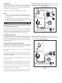
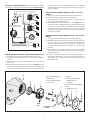
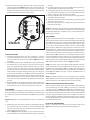
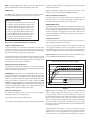
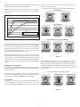
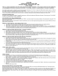
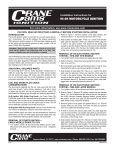
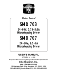
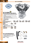
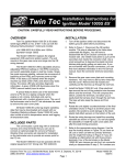
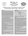
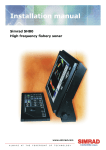
Instruction 510-0277
12-15-14
Copyright © 2014
by S&S® Cycle, Inc.
S&S Cycle, Inc
All rights reserved.
Printed in the U.S.A.
®
.
14025 Cty Hwy G PO Box 215
Viola, Wisconsin 54664
Phone: 608-627-1497 • Fax: 608-627-1488
Technical Service Phone: 608-627-TECH (8324)
Technical Service Email: [email protected]
Website: www.sscycle.com
Installation Instructions for HI-4N Motorcycle Ignition
DISCLAIMER:
S&S parts are designed for high performance, closed course, racing
applications and are intended for the very experienced rider only. The
installation of S&S parts may void or adversely affect your factory warranty.
In addition such installation and use may violate certain federal, state, and
local laws, rules and ordinances as well as other laws when used on motor
vehicles used on public highways, especially in states where pollution laws
may apply. Always check federal, state, and local laws before modifying your
motorcycle. It is the sole and exclusive responsibility of the user to determine
the suitability of the product for his or her use, and the user shall assume all
legal, personal injury risk and liability and all other obligations, duties, and
risks associated therewith.
The words Harley®, Harley-Davidson®, H-D®, Sportster®, Evolution®, and all
H-D part numbers and model designations are used in reference only. S&S
Cycle is not associated with Harley-Davidson, Inc.
IMPORTANT NOTICE:
Statements in this instruction sheet preceded by the following words are of
special significance.
WARNING
Means there is the possibility of injury to yourself or others.
CAUTION
Means there is the possibility of damage to the part or motorcycle.
NOTE
Other information of particular importance has been placed in italic type.
S&S recommends you take special notice of these items.
WARRANTY:
SAFE INSTALLATION AND OPERATION RULES:
Before installing your new S&S part it is your responsibility to read and follow
the installation and maintenance procedures in these instructions and
follow the basic rules below for your personal safety.
•• Gasoline is extremely flammable and explosive under certain conditions
and toxic when breathed. Do not smoke. Perform installation in a well
ventilated area away from open flames or sparks.
•• If motorcycle has been running, wait until engine and exhaust pipes
have cooled down to avoid getting burned before performing any
installation steps.
•• Before performing any installation steps disconnect battery to eliminate
potential sparks and inadvertent engagement of starter while working
on electrical components.
•• Read instructions thoroughly and carefully so all procedures are
completely understood before performing any installation steps.
Contact S&S with any questions you may have if any steps are unclear or
any abnormalities occur during installation or operation of motorcycle
with a S&S part on it.
•• Consult an appropriate service manual for your motorcycle for correct
disassembly and reassembly procedures for any parts that need to be
removed to facilitate installation.
•• Use good judgment when performing installation and operating
motorcycle. Good judgment begins with a clear head. Don’t let
alcohol, drugs or fatigue impair your judgment. Start installation when
you are fresh.
•• Be sure all federal, state and local laws are obeyed with the installation.
•• For optimum performance and safety and to minimize potential
damage to carb or other components, use all mounting hardware that is
provided and follow all installation instructions.
•• Motorcycle exhaust fumes are toxic and poisonous and must not be
breathed. Run motorcycle in a well ventilated area where fumes can
dissipate.
All S&S parts are guaranteed to the original purchaser to be free of
manufacturing defects in materials and workmanship for a period of thirtysix (36) months from the date of purchase. Merchandise that fails to conform
to these conditions will be repaired or replaced at S&S’s option if the parts
are returned to us by the purchaser within the 36-month warranty period or
within 10 days thereafter.
In the event warranty service is required, the original purchaser must call or
write S&S immediately with the problem. Some problems can be rectified by a
telephone call and need no further course of action.
A part that is suspect of being defective must not be replaced by a Dealer
without prior authorization from S&S. If it is deemed necessary for S&S to
make an evaluation to determine whether the part was defective, a return
authorization number must be obtained from S&S. The parts must be packaged
properly so as to not cause further damage and be returned prepaid to S&S
with a copy of the original invoice of purchase and a detailed letter outlining
the nature of the problem, how the part was used and the circumstances at
the time of failure. If after an evaluation has been made by S&S and the part
was found to be defective, repair, replacement or refund will be granted.
ADDITIONAL WARRANTY PROVISIONS:
(1) S&S shall have no obligation in the event an S&S part is modified by any
other person or organization.
(2) S&S shall have no obligation if an S&S part becomes defective in whole or
in part as a result of improper installation, improper maintenance, improper
use, abnormal operation, or any other misuse or mistreatment of the S&S part.
(3) S&S shall not be liable for any consequential or incidental damages
resulting from the failure of an S&S part, the breach of any warranties, the
failure to deliver, delay in delivery, delivery in non-conforming condition, or
for any other breach of contract or duty between S&S and a customer.
(4) S&S parts are designed exclusively for use in Harley-Davidson® and other
American v-twin motorcycles. S&S shall have no warranty or liability obligation
if an S&S part is used in any other application.
INTRODUCTION
The HI-4N ignition system is intended for use on Harley-Davidson®
motorcycles. The HI-4N replaces the original equipment (OE) point or
electronic ignition system on 1970 - 1999 big twin (except Twin Cam
88®) and 1971 - 1990 Sportster® models.
HI-4N Ignition With Stock-Style Dual Fire Coil. Dual fire mode
(sometimes called Wasted Spark) is designed to use the stock ignition
coil on most applications. Refer to Figure 1.
HI-4N Dual Fire System Hookup
IGNITION
SWITCH
The HI-4N is also perfect for S&S high performance engines.
–
+12V
O.E. WHITE WIRE
TO COIL +
+
IGNITION
COIL
WHITE
12 VOLT
BATTERY
NOTES
•
If cam cover on Sportster models has been replaced with a newer
replacement part, the HI-4N may not fit due inadequate clearance in
the ignition cavity.
•
HI-4N may be used with 1969 and earlier big twin models if a 12V
electrical system, a special timer designed for 1970-’99 ignition
system, and reverse timer gears have been installed.
FRONT
S&S/Viola V-Twin SPARK PLUG
550-0500
GROUND
MODE SWITCH MUST BE SET TO 4, 5, 6, 7,
OR 9 FOR DUAL FIRE APPLICATIONS
REAR
SPARK PLUG
PINK
MODE
BROWN
ADVANCE RATE
WARNING
X1000
RPM LIMIT
X100
1996 and later models have a vehicle tilt sensor that shuts off the
ignition if the motorcycle rolls on its side. This feature is disabled
when the HI-4N ignition is installed.
RPMX100
HI-4N IGNITION
VIOLET
TAPE UP UNUSED
NOTE:
BLUE WIRE
If tach is not used, tape up brown wire.
If VOES is not used, either tape up violet
wire or connect to ground depending on
application.
The HI-4N features state-of-the-art technology that allows adjustable
advance and rev limit. A timing LED indicates static timing (top dead
center). Two starting modes are provided: electric start and kick start. A
tach output gives accurate tach readings even at the rev limit.
VOES
(VACUUM SWITCH)
Figure 1
ADDITIONAL REQUIRED PARTS
FX series Big Twin® and XL series Sportster® models prior to 1984, FL
series Big Twin® models prior to 1985, and all models with OE points
will require OE Part # 32402-83 or S&S part # 55-1247 timing rotor.
This part is not included with the HI-4N installation kit and must be
purchased separately,
HI-4N Ignition With Single Plug Heads. The prefered method is to
use a single fire coil, which will fit in the stock mounting location on
most H-D® motorcycles. Refer to Figure 2.
HI-4N Single Fire System Hookup with Single Plug Heads
IGNITION
SWITCH
COIL AND SPARK PLUG CABLE CONSIDERATIONS
We recommend replacing the OE coil. Coils used with the HI-4N must
have at least 2 ohms primary resistance. Coils with 4 ohms or higher
may be used, but may not produce optimum output.
O.E. WHITE WIRE
TO COIL +
+12V
–
+
12 VOLT
BATTERY
GROUND
We recommend the following coils for single and dual-plug
applications:
MODE SWITCH MUST BE SET TO 0, 1, 2, 3,
OR 8 FOR SINGLE FIRE APPLICATIONS
For dual fire applications or single fire applications where two dual fire
coils may be needed (Figure 3, dual plug heads) we recommend S&S/
Viola V-twin P/N: 550-0500.
FRONT
SPARK PLUG
REAR
SPARK PLUG
PINK
MODE
ADVANCE RATE
X1000
RPM LIMIT
X100
For single fire applications with single plug heads, we recommend S&S
part number 55-1571.
HI-4N IGNITION
WHITE
S&S
55-1571
BLUE
BROWN
RPMX100
VIOLET
The HI-4N is designed for use with suppression core, carbon or spiral
core spark plug cables. Spiral core spark plug cables such as S&S/Viola
V-twin P/N: 550-0524 are recommended for maximum performance.
NOTE
If tach is not used, tape up brown wire.
If VOES is not used, tape violet wire or connect
violet wire to ground depending on application.
Do not use solid wire spark plug cables; they may cause interference
with your ignition system and accessories.
Figure 2
The figures that follow illustrate wiring connections for different
applications and will be described in detail later in this instruction:
2
VOES
(VACUUM SWITCH)
HI-4N Ignition With Dual Plug Heads. Use two dual fire coils. You will
have to fabricate a bracket to mount the second coil. Refer to Figure 3.
enough to start the engine. Remove and save the two standoffs
and washers. Remove the breaker plate assembly, wiring, cam, and
advance assembly.
HI-4 Single Fire System Hookup with Dual Plug Heads
IGNITION
SWITCH
IGNITION
COIL
+12V
–
REMOVAL OF OE ELECTRONIC IGNITION SYSTEM—1978 & 1979
MODELS
1. Turn ignition switch off and disconnect battery ground cable.
2. Disconnect wires going from ignition module to coil.
3. Remove ignition cover plate and hardware. Save these items for
later re-use. Remove ignition module.
4. Note location of timer plate. There is a V-notch (Figure 5) in the
timer plate used for alignment. When you install the HI-4N, align
the V-notch in the same location. This should set the timing close
enough to start the engine. Remove and save the two standoffs
and washers. Remove the sensor, shield, timer plate, trigger rotor,
and advance assembly.
S&S/Viola V-Twin
550-0500
O.E. WHITE WIRE
TO COIL +
FRONT COIL
AND
SPARK PLUGS
+
12 VOLT
BATTERY
GROUND
S&S/Viola V-Twin
550-0500
IGNITION
COIL
WHITE
PINK
MODE SWITCH MUST BE SET TO 0, 1, 2, 3,
OR 8 FOR SINGLE FIRE APPLICATIONS
REAR COIL
AND
SPARK PLUGS
MODE
BLUE
ADVANCE RATE
X1000
RPM LIMIT
REMOVAL OF OE ELECTRONIC IGNITION SYSTEM—1980 & LATER
MODELS
1. Turn ignition switch off and disconnect battery ground cable.
2. Remove OE ignition module and wire harness. You will disconnect
two wires at the coil, wire going to the VOES (Vacuum Operated
Electrical Switch), ground wire at the module, and the 3 pin
plug that connects to the sensor plate. Refer to shop manual for
locations.
3. Remove ignition cover plates and gasket. This will require drilling
out two rivets. The rivets will later be replaced with two supplied
self threading screws.
4. In order to remove the sensor plate cable, the cable plug must be
removed first. Use needle nose pliers to pull the terminals out of
the plug. Then pull the cable through the exit hole at the bottom
of the timing cover.
X100
BROWN
HI-4N IGNITION
RPMX100
VIOLET
NOTE
If tach is not used, tape up brown wire.
If VOES is not used, tape up violet wire or connect
to ground depending on application.
VOES
(VACUUM SWITCH)
Figure 3
REMOVAL OF POINTS IGNITION — EARLY MODELS PRIOR TO 1978
1. Turn ignition switch off and disconnect battery ground cable.
2. Disconnect wire going from breaker points to Coil– (negative)
terminal.
3. Remove ignition cover plate, and hardware. Save these items for
later re-use.
4. Note location of breaker plate. There is a V-notch (Figure 5) in the
breaker plate used for alignment. When you install the HI-4N, align
the V-notch in the same location. This should set the timing close
10
1. Buttonhead Screws (2)
2. Outer Cover
9
3. Inner Cover Screws (2)
4. Inner Cover
7
8
6
HI-4N
Unit
Use Supplied
Gasket
Figure 4
3
5
5. Gasket
6. Sensor Plate Screws &
Washers (2 each)
7. HI-4N Unit
8. Rotor Screw & Star Washer
9. Rotor
10. Gear Case Cover
4
2
3
1
5. Note location of sensor plate. There is a V-notch in the sensor plate
used for alignment. See Figure 5. When you install the HI-4N, you
should align the V notch in the same location. This should set the
timing close enough to start the engine. Remove and save the two
standoffs and washers. Remove the sensor plate.
terminal.
3. For dual fire applications, connect the HI-4N pink wire to the Coil –
(negative) terminal, and tape up the blue wire
4. For single fire applications, connect the pink wire to the terminal on
the coil for the front cylinder, and connect the HI-4N blue wire to
the Coil – terminal on the coil for the rear cylinder.
5. Connect the HI-4N brown wire to the tach wire, if equipped with a
tachometer. Tape up if unused.
6. The HI-4N is grounded via the timing housing; a separate ground
connection is not required.
7. Reconnect battery ground cable. Verify proper ground connections
to the frame and engine.
MODE
ADVANCE RATE
NOTE: Most motorcycle coils do not have terminals marked. Most single
fire coils use the center terminal for +12V and the outer two terminals for
front and rear cylinder Coil–. For dual fire coils use either terminal for Coil+
and the other one for Coil–.
X1000
RPM LIMIT
X100
VOES HOOKUP
The OE vacuum operated electrical switch (VOES) is an open circuit
when vacuum is below the setting of the switch. Lighter bikes generally
have a VOES that opens at 3-5 inch-Hg, while the VOES used in heavier
bikes such as touring models and on high performance engines. open
at 6-7 in Hg. In low load operation when vacuum is above the VOES
switch point, the VOES closes and grounds the vacuum input on the
module. When this condition exists, the module uses the High Vacuum
or Full Advance curve which provides more advance. When engine is
under a load with throttle partially to fully open, manifold vacuum is
reduced and the VOES opens the circuit, causing the module to switch
to the Retarded Curve with less advance. This is designed to prevent
knock on acceleration or under heavy loads, but allows full advance at
cruising speeds, improving driveability and fuel economy. Connect the
VOES to the HI- 4N violet wire as shown in Figures 1, 2, or 3.
V-Notch
Figure 5
HI-4N INSTALLATION
1. The HI-4N requires OE timing rotor Part # 32402-83, or S&S Part
# 55-1247. For models prior to 1980, use the supplied 10-32 x 3/4”
screw and washer to mount the rotor. Refer to Figure 4 for parts
installation
2. Install HI-4N system in place of OE breaker or sensor plate. Rotate
the HI-4N about 90˚ to give better access to the cable exit hole in
the gear cover. On some early models it may be necessary to enlarge
the cable exit hole. It is often easier to push the cable through the
hole first, and tuck the cable into the cable indent in the base of the
module when inserting the module into the gear cover. Align the
V-notch on the HI-4N same as the OE plate you removed. Use the
OE standoffs to secure the HI-4N. You may need to use lock washers
under the standoffs for proper clearance between the HI-4N and
cover plate. Do not fully tighten the standoffs until the timing has
been set.
3. Route the HI-4N harness along the frame rails to the coil. Make sure
that harness will not be chafed or burned by exhaust heat. Secure
harness with tie wraps. Do not install timing cover at this time.
NOTE: If you choose not to use the VOES, you may ground the violet wire,
to force the module to use the Full Advance curves, or tape it up to use the
Retarded Curves. Grounding the VOES wire in Race mode will effectively
bypass the setting of the Advance Rate switch and cause the module to
provide Maximum advance since there is only one Full Advance curve as
shown in Figure 7.
NOTE: 1996 and later models use a 2 wire connector between the VOES
and the OE harness. Connect one wire from the VOES to frame ground and
connect the other wire to the VOES input (violet wire) on the HI-4N.
MODELS WITHOUT OE VACUUM SWITCH (VOES)
This includes most models prior to 1985. Fuel economy and driveability
will be improved if you install a VOES and connect it to the HI-4N
violet wire as shown in Figures 1, 2, and 3. We recommend you use
H-D® VOES P/N 26566-91 or S&S/Viola V-twin P/N 550-0399 for lighter
bikes with stock to mild engines and S&S/Viola V-twin P/N 55-1248 for
touring and high performance applications. If a VOES is not used, the
violet wire may be grounded to use the Full Advance curve, or taped
up to use the Retarded curve, depending on the application and timing
requirements of the engine.
HI-4N HOOKUP
Crimp terminals and hardware are supplied for your convenience. Use
the ring terminals for coil hookup. Use male-female quick disconnects
for connections to the tach and vacuum switch (VOES). Tape up unused
wires.
Note: Damage will result if the brown tach wire comes in contact with
+12V.
HI-4N SETUP AND OPERATION
Below is a description of the function for each switch. Refer to the
Figure 5 to locate rotary switches for the following functions.
1. Identify switched +12 volt wire and tach wire (if equipped) going to
the coil. Refer to your service manual, or reconnect the battery and
use a test light or voltmeter. The switched +12 volt wire will be hot
when the ignition key is turned on.
2. Refer to Figure 1, 2, or 3 depending on your application. Connect
the HI-4N white wire and switched +12 volt wire to Coil + (positive)
4
NOTE - After changing switch settings, you must cycle ignition power
(ignition switch ON – OFF –ON) for those changes to take effect.
the OE curve ignition timing is too aggressive and cannot be adjusted
to eliminate spark knock.
MODE Switch
Additional information regarding the ignition timing curves can be
found in the section describing the ADVANCE RATE Switch.
The MODE switch controls several aspects of the HI-4N’s operation.
The table below briefly describes the operation in each mode:
Kick Start and Electric Start Modes
Kick Start modes fire on the first revolution of the engine for easier
kick-starting. Electric start modes delay firing the spark plugs for 2
revolutions of the engine to reduce strain on the starter.
MODE SWITCH SETTINGS
0 Single Fire, Single Spark, Race Curve, Electric Start
1 Single Fire, Single Spark, OE Curve, Electric Start
2 Single Fire, Multi Spark, Race Curve, Electric Start
3 Single Fire, Multi Spark, OE Curve, Electric Start
4 Dual Fire, Single Spark, Race Curve, Electric Start
5 Dual Fire, Single Spark, OE Curve, Electric Start
6 Dual Fire, Multi Spark, Race Curve, Electric Start
7 Dual Fire, Multi Spark, OE Curve, Electric Start
8 Single Fire, Single Spark, OE Curve, Kick Start
9 Dual Fire, Single Spark, OE Curve, Kick Start
ADVANCE RATE Switch
The ADVANCE RATE switch adjusts the “aggressiveness” of the curves
with a setting of 0 being the least aggressive and a setting of 9 being
the most aggressive. ADVANCE RATE switch settings between 0 and
9 select progressively more aggressive curves, with a setting of 4 or
5 being about halfway in between and 7 being about 75% of the way
towards the MAX setting.
Timing Considerations
It is important that you understand the timing marks in your engine, as
well as the timing required for your engine.
Below are more detailed descriptions of each mode:
Single Fire and Dual Fire Modes
In Single Fire mode, each cylinder fires independently and only on the
compression stroke (once every other revolution). The exception to
this is when in Single Fire, Kick Start mode, the HI-4N fires both plugs at
the same time during starting to reduce plug fouling.
If you carry a passenger, pull a trailer, or are using low octane gasoline,
a less aggressive advance curve may be required to reduce spark
knock. More aggressive advance curves will give higher performance,
but may require the use of high-octane gasoline to avoid spark knock.
Figures 6 and 7 show the sets of timing curves that the HI-4N will run
based on MODE and ADVANCE RATE switch settings:
Dual fire mode (sometimes called Wasted Spark) is designed to use the
stock ignition coil on most applications. In Dual Fire mode, the spark
plugs for both cylinders fire at the same time when either cylinder is on
the compression stroke (once per revolution).
S&S HI-4N OE ADVANCE CURVE RANGE
40
Multi Spark and Single Spark Modes
In the Multi Spark modes, the HI-4N delivers a series of sparks after the
initial spark to reduce lean surge and plug fouling. Single Spark mode
delivers one spark per ignition event.
35
ADVANCE DEGREES
30
Important! Do not attempt to use a timing light when the HI-4N is
running in Multi Spark mode. Doing so could result in incorrect timing
adjustment. Instead, set the MODE switch to the equivalent Single Spark
mode when setting timing and then back to Multi Spark mode when
finished. For example, if you want to run in mode 3 (Single Fire, Multi
Spark, OE Curve, Electric Start), set the timing with the mode switch set to
1 (Single Fire, Single Spark, OE Curve, Electric Start), then switch back to
mode 3 when you are finished. Again, be sure to cycle ignition power after
changing switch settings for the change to take effect.
25
20
15
10
FULL ADVANCE CURVE - VOES CLOSED - POSITION 9
RETARDED CURVE - VOES OPEN - POSITON 9
FULL ADVANCE CURVE - VOES CLOSED - POSITION 0
5
RETARDED CURVE - VOES OPEN - POSITION 0
0
0
1000
2000
3000
4000
5000
6000
7000
8000
RPM
Figure 6
Figure 6 shows the available range of Full Advance and Retarded
curves available in OE Mode. Under low load conditions such as
cruising at a steady speed on a level road, the throttle is not open very
far and manifold vacuum will be higher than the switch point of the
VOES. The switch will be closed, causing the module to use the Full
Advance curve. When the load on the engine increases and the throttle
is opened, vacuum is reduced below the VOES Switch point, causing
the switch to open. The module will then switch to the Retarded Curve
to prevent spark knock.
OE and Race Timing Curves
The HI-4N comes with the option to use one of two sets of ignition
timing advance curves as described below:
- OE curves for stock to mildly modified engines.
- Race curves are for highly modified, high compression engines where
Setting the Advance Rate switch to 0 (solid lines) will select the least
aggressive pair of curves, and setting the switch to higher numbers
will select from a series of progressively more aggressive curves that
increase both the rate of advance and the total advance of the Full
5
Advance and Retarded curves. Setting 9 (dashed lines) will result in the
most aggressive curves and maximum total advance.
flywheels. Early Style includes most 1970-’80
includes most 1981-’95 models.
models. Late Style
Timing Marks For Harley-Davidson® Engines With Stock Flywheels
Figure 7 shows the range of curves available in Race Mode. Note that
the Full Advance curve is that same for all positions of the Advance
Rate switch.
1970-'80 Models
Front Cylinder TDC Mark
S&S HI-4N RACE ADVANCE CURVE RANGE
Early Style
1936-'80
40
35
ADVANCE DEGREES
Front Cylinder 35°
Advance Mark
Front Cylinder TDC Mark
30
1981-'95 Models
25
20
15
10
FULL ADVANCE CURVE - VOES CLOSED - ALL POSITIONS
RETARDED CURVE- VOES OPEN - POSITION 9
RETARDED CURVE - VOES OPEN - POSITION 0
5
Front Cylinder TDC Mark
0
0
1000
2000
3000
4000
5000
6000
7000
8000
Front Cylinder 35°
Advance Mark
Rear Cylinder 35°
Advance Mark
RPM
Figure 7
1996-'99 Models (1995-'99 Export Models)
The Retarded Curves in the Race Mode, which will be activated when
the engine is under a load and manifold vacuum is lower than the VOES
switch point, provide less aggressive advance rates and more retarded
timing than the OE Mode. This allows tuners to accommodate large,
high compression engines that do not need and generally cannot
tolerate as much ignition advance under a load.
Front Cylinder TDC Mark
Setting the Advance Rate switch to 0 selects the least aggressive
Retarded Curve, and setting the switch to higher numbers selects from
a series of progressively more aggressive Retarded curves that increase
both the rate of advance and the total advance of the Retarded curve.
Setting 9 will result in the most aggressive curves and maximum total
advance.
Front Cylinder 35°
Advance Mark
Front Cylinder 20° Mark
DO NOT USE
Figure 8
Refer to Figure 9 for timing marks on S&S flywheels. The advance
timing marks on S&S flywheels vary by application. Refer to the S&S
flywheel timing mark charts for details The Year Code refers to letters
contained in the flywheel identification code that is stamped on the
side of the flywheel. This can also be observed through the timing
inspection hole.
RPM LIMIT (Rev Limit) Switches
The RPM limit switches (RPM LIMIT) are adjustable from 1,500 to 7,500
RPM. Use a safe RPM limit for your engine. Do not set RPM limit below
1,500 or above 7,500.
Timing Marks For Engines With S&S Flywheels
The top, “X1000” switch adjusts the rev limit in 1000 RPM increments
and the “X100” switch adjusts the rev limit in 100 RPM increments. The
rev limit on the HI-4N shown in Figure 5 is set to 5500 RPM.
Cylinder TDC Mark Cylinder TDC M
T F
Timing Marks
The TDC and advance timing marks are located on the flywheel and
can be observed though the timing inspection hole (refer to shop
manual for details). Refer to Figure 8 for typical timing marks on stock
Front Cylinder TDC Mark
F
Front Cylinder
Advance Mark
Figure 9
6
t Cylinder TDC M
R
RearCylinder
Advance Mark
S&S Flywheel Timing Marks for Harley-Davidson® Big
Twin Models
Year Code
Engine
Year/Description
Advanced Timing
Marks (deg BTDC)
E
1936 – 1954 Big Twin
35°
L
1955 – 1971 Big Twin
35°
AL
1972 – Early 1981 Big 35°
Twin
SE
1955 – Early 1981 Big 35°
Twin
SL
Late 1981 – 1999 Big 35°
Twin
SG
S&S 4 1/8” Bore Big 30°
Twin
SM
1995 – 1999 EFI Big 35°
Twin
Verify that the front cylnder is on compression stroke by observing the
position of the timing cup See Picture 1 for big twin or Picture 2 for
Sportster® models. Refer to Figure 8 or 9 and find the diagram with a
matching TDC mark. Use the corresponding advance mark shown in
the diagram for setting timing as described in the dynamic timing
procedure (setting timing using a timing light).
S&S Flywheel Timing Marks for Harley-Davidson®
Sportster® Models
Year Code
Engine
Year/Description
Advanced Timing
Marks (deg BTDC)
None
1957 – 1976 XL
40°
B
1957 – Early 1981 XL
40°
SB
1957 – Early 1981 XL
40°
BD
1957 – Early 1981 XL
40°
SBD
1957 – Early 1981 XL
40°
SCD
Late 1981 – 1985 XL
40°
D
Late 1986 – Up XL
30°
KRS
45” WR/KR
30°
Picture 1
NOTE: 1996 and later models (1995 and later for export models) have a
timing mark at 20° BTDC for setting the timing with the OE ignition module.
Do not use this mark for setting the timing on the HI-4N. In most cases an
additional mark will remain at 35° BTDC (see Figure 8). Use this mark to
set the timing with a timing light as described below. If unsure of which
timing marks to use, remove spark plugs, turn engine while observing
the marks that appear in the timing inspection hole. See Figure 10 As
the front cylinder approaches TDC, the first mark to appear will be the
front cylinder advance mark. Next you may be able to see the crankpin
nut relief. the next mark to appear will be the TDC mark for the front
cylinder.
Picture 2
Timing The HI-4N Module
NOTES
•
Do not attempt to use a timing light when the HI-4N is running in
Multi Spark mode. Doing so could result in false timing adjustment.
Instead, set the MODE switch to the equivalent Single Spark mode
when setting timing and then back to Multi Spark mode when
finished. For example, if you want to run in mode 3 (Single Fire, Multi
Spark, OE Curve, Electric Start), set the timing with the mode switch
set to 1 (Single Fire, Single Spark, OE Curve, Electric Start), then
switch back to mode 3 when you are finished. Again, be sure to cycle
ignition power after changing switch settings for the change to take
effect.
•
Dynamic timing procedure will change settings made in the static
timing procedure if the module is moved.
•
For applications where initial timing is critical, it is important to
understand the range of ignition timing the HI-4N will produce based
on MODE and ADVANCE RATE switch settings and what initial timing
will result based on the dynamic timing procedure (setting timing
using timing light).
•
If using a standard non-adjustable timing light, on an engine with a
FLYWHEEL ROTATION
FRONT CYLINDER
TDC MARK
FRONT CYLINDER
ADVANCE MARK
CRANKPIN NUT RELIEF
Figure 10
7
•
•
•
Initial Static Timing Procedure
In most cases, aligning the V-Notch on the HI-4N plate to the same
location as the OE plate will set the timing close enough to start the
engine. See Figure 5.
35 deg advance timing mark, timing will correspond to the charts in
Figures 6 and 7. On engines with different timing marks, such as
Sportster® models and S&S 4 1/8” bore engines, the timing charts will
be shifted based on the advanced timing mark location. For example,
for 1200cc Sportster models with the advance timing mark at 40 deg
BTDC, initial and advanced timing will be shifted 5 deg advanced.
The timing inspection hole is about 10° wide. Placing a timing mark
at the left edge of the hole will retard timing by approximately 5°,
while placing a timing mark at the right edge of the hole will advance
timing by 5°.
Most dial back timing lights do not provide accurate timing with dual
fire systems. Refer to your timing light’s instruction manual. If you
are running in dual fire mode, set the timing light to 0 deg and time
according to the procedure for a standard timing light.
If after setting initial timing, you find that starting is poor, you can try
advancing the initial timing. You can increase the advance by rotating
the ignition clockwise as shown by the “ADV” marking and arrow on
the ignition near the MODE switch. You can use the tic marks on the
outside of the HI-4N mounting slots for timing reference. There is 10
deg between the large tic marks and 5 deg between the large and
small tic marks See Figure 11. Most kick start applications work
better with an initial timing of 8 deg BTDC. Electric start applications
work well with an initial timing of 5 deg BTDC. Note that this will also
increase the total advance timing by the same amount.
If the engine will not start or runs very rough, you can use the following
static timing procedure:
1) Be sure the ignition is off, remove the spark plugs, and turn the engine
until the piston in the front cylinder is coming up on compression
stroke.
2) Rotate the engine until the TDC (Top Dead Center) timing mark is
centered in the inspection hole (See Figures 8 and 9 for timing marks
or refer to your factory service manual).
3) Verify that the engine is indeed on TDC compression stroke. This can
be verified by viewing the position of the rotor cup in the cam chest
(For big twins see Picture 1. For Sportster Models see Picture 2) .
4) Ground spark plugs or spark plug wires with alligator clips to avoid
electrical shock and possible damage to the coil.
5) Turn on the ignition, loosen the sensor plate screws holding the HI4N and rotate the unit clockwise until the timing LED goes off. In some
instances, you may need to rotate the unit full counter-clockwise, then
clockwise again for this to happen. The point at which the LED goes off
is TDC. So, the initial timing is now at TDC.
6) Tighten the sensor plate screws, turn off ignition, and reinstall the
spark plugs.
7) Engine can now be started and timing confirmed or adjusted with
a timing light.
Dynamic Timing Procedure (Setting Timing Using A Timing Light)
1) This timing procedure requires that a VOES be connected to the HI4N. For applications where a VOES is not used, ground the VOES input
(HI-4N violet wire) to force the module to use the Full Advance curve
while setting the timing with a timing light.
2) Connect a timing light to the front cylinder.
3) Set the HI-4N ADVANCE RATE switch to 9 (MAX Advance).
4) Run the engine at 2,500 RPM.
5) If using a standard non adjustable timing light, rotate the HI-4N
module until the advance timing mark is centered in the observation
hole.
6) If using an adjustable (dial back) timing light, set the light to the
desired advance and rotate the HI-4N module until the TDC timing
mark is centered in the observation hole.
7) Tighten the standoffs and verify timing has not shifted.
8) Be sure to put your MODE and ADVANCE RATE switch settings in
the desired position after you have completed the dynamic timing
procedure.
9) For 1200cc Sportster® models, it is recommended that the 40°
advanced timing mark be centered in the timing hole with a standard
timing light or the TDC mark be centered in the hole with an adjustable,
dial back timing light set at 40°. 883cc engines should be timed to 40°
by setting the advance timing mark to left side of the inspection hole
using a standard timing light, or by centering the TDC mark with a dial
back timing light set at 40°.
10) Refer to the following chart for recommended settings for S&S
engines.
10˚ TIMING DIFFERENCE
BETWEEN LARGE TIC MARKS
5˚ TIMING DIFFERENCE
BETWEEN LARGE AND
SMALL TIC MARKS
Figure 11
Theses are recommended, initial settings only. Factors such as
vehicle weight, fuel quality, and riding climate may affect settings. If
detonation is encountered, you may need to retard timing further or
performance may be improved by advancing timing.
All complete S&S engines use S&S/Viola V-twin VOES P/N: 55-1248.
8
Recommended Settings for S&S Engines
Engine
C urve ADVANCE Advance
Family RATE
Timing
Marks
(deg
BTDC)
B ase Notes For Dynamic Timing
Timing
Offset
SB100
Race
0°
0°
30°
Dynamic time with OE curve, ADV RATE = 9, and VOES DISCONNECTED using timing
mark
V145
Race
5°
30°
-5°
Dynamic time with VOES grounded using timing mark
V124
Race
0°
30°
-1°
Dynamic time with OE curve, ADV RATE = 0, and VOES GROUNDED using timing mark
@ 3000 RPM
V117
Race
0°
30°
0°
Dynamic time with OE curve, ADV RATE = 9, and VOES DISCONNECTED using timing
mark
V113
Race
0°
35°
-1°
Use dial-back timing light and set at 34 deg BTDC w/VOES Grounded
V111
Race
2°
30°
0°
Dynamic time with OE curve, ADV RATE = 9, and VOES DISCONNECTED using timing
mark
V96
Race
0°
35°
-3°
Use dial-back timing light and set at 32 deg BTDC w/VOES Grounded
V80
Race
5°
35°
0°
Dynamic time with VOES grounded using timing mark
SH80
OE
9°
35°
0°
Dynamic time with VOES grounded using timing mark
SH93
Race
2°
35°
0°
Dynamic time with VOES grounded using timing mark
SH93H
Race
0°
35°
0°
Dynamic time with VOES grounded using timing mark
SH103
Race
0°
35°
-2°
Use dial-back timing light and set at 33 deg BTDC w/VOES Grounded
P74
OE
9°
35°
0°
Dynamic time with VOES grounded using timing mark
P93
Race
2°
35°
0°
Dynamic time with VOES grounded using timing mark
P93H
Race
0°
35°
0°
Dynamic time with VOES grounded using timing mark
P103H
Race
0°
35°
-2°
Use dial-back timing light and set at 33 deg BTDC w/VOES Grounded
KN74
OE
0°
35°
9°
Use dial-back timing light and set at 40 deg BTDC w/VOES Grounded
KN93
OE
0°
35°
9°
Use dial-back timing light and set at 40 deg BTDC w/VOES Grounded
Note: Reconnect VOES for normal operation. DISCONNECT or GROUND VOES wire only for timing purposes.
Kick start modes only available with OE curves. If you are running a high
compression, kick-start engine, start with ADVANCE RATE = 0, and retard
ignition timing by rotating HI-4N counter clockwise if detonation occurs.
the frame behind the seat. In order to provide a dedicated ground for the
high starter current, another cable should be installed from the point on
the frame that the battery is already grounded to the starter mounting
flange. This cable should be the same diameter as the battery ground cable
presently on the bike, and will help prevent damage to your electronic
components.
COVER PLATE ASSEMBLY
You can re-use the OE hardware, and the supplied S&S gasket for the
HI-4N. For models with a riveted outer cover, use the supplied selfthreading screws in place of the rivets.
1. Check that timing LED lights up and stays on when ignition key is
first turned on. If not, check for +12 volts on white wire from HI-4N.
2. Check that timing LED blinks while engine is cranked.
3. If the timing LED blinks, but engine will not start, recheck all wire
harness connections or replace coil(s).
4. Check for low voltage from a faulty or marginal charging system
and battery.
5. If all of the above conditions have been checked, contact S&S
Technical Support, 1-866-244-2673 for assistance
TROUBLESHOOTING
Did the engine run properly before installation of the HI-4N? If not,
remove the HI-4N, reinstall the OE ignition or another known good unit
and then find and correct the original problem. Did the HI-4N function
correctly before the problem occurred? If the answer is yes, did you
change anything that may have affected it? Try going back to the last
setup that worked OK to help isolate the problem.
CHECKING FOR SPARK
To crank the engine and check for spark, use a KD Tools test plug or
H-D® tool HD-26792. These test plugs come with an alligator clip that
must be attached to frame or engine ground. Use a length of spark
plug wire to connect the test plug to the coil.
If the engine will not start, or runs rough or intermittently, use the
following checklist steps:
ENGINE WILL NOT START
NOTE: The battery ground on most Harley-Davidsons® is connected to
9
WARNING
Never crank the engine with any spark plug wire disconnected.
MISFIRE OR INTERMITTENT OPERATION
Field experience has shown that popping back through the carburetor,
misfiring, and intermittent failure (especially after the engine gets
hot) are usually not caused by electrical problems within the HI-4N.
Carburetor problems, fouled spark plugs, coil failure, and loose wire
harness connections are the most common culprits. Also, verify that
spiral core or suppression type spark plug wires and resistor spark
plugs are being used.
TACH INOPERATIVE
If the tach is inoperative after installation of the HI-4N, you may require
a tach adapter. The HI-4N tach output is compatible with ground
sensing tachs which includes most OE and aftermarket tachs. Some
tachs require a high voltage trigger pulse. In this case, a tach adapter
will need to be purchased separately. Note that the tach will read
correctly at the rev limit only if it is connected to the brown wire from
the HI-4N. Damage to the HI-4N circuitry may have occurred if 12 volts
was applied to the brown tach wire at any time.
10