1
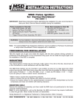
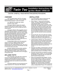
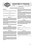
V-Twin Mfg.
V-TECH 3 IGNITION KIT, DUAL FIRE
FITS EVO, SHOVEL, SPORTSTER 1970 - 1998
VT No. 32-9501
This is a custom application and rider safety depends on proper installation. This product should only be installed by
a knowledgeable and trained motorcycle technician. V-Twin Mfg. accepts no responsibility for improper installation.
The V-TECH 3 ignition system is intended for use with Harley-Davidson motorcycles, The V-Tech 3 replaces the OEM electronic ignition system on 1978 and
later models and the points and mechanical advance on early models.
The V-TECH 3 features an adjustable advance and rev limiter, a timing LED that indicates static timing (top dead center) and gives diagnostic information.
The two starting modes provided are electric start and kick start. A tachometer output gives accurate tachometer readings even at the rev limit.
ADDITIONAL REQUIRED PARTS
FX series BT and XL models prior to 1984, FL series BT models prior to 1985 and all models with OEM points will require V-Twin timing rotor VT No.32-9087.
This part is not included with the V-TECH 3 installation kit.
COIL AND SPARK PLUG CABLE CONSIDERATIONS
We recommend replacing the OEM coil. Coils used with the V-TECH 3 must have at least 2 ohms primary resistance, We recommend the using the VT 329225 coil for optimum results.
Spiral core spark plug wires are recommended for maximum performance, Do not use solid copper spark plug cables, they may cause interference with your
ignition system and accessories.
REMOVAL OF POINTS IGNITION – EARLY MODELS PRIOR TO 1978
1. Turn ignition switch off and disconnect battery ground cable. Disconnect wire going from breaker points to Coil- (negative) terminal.
2. Refer to figure 1, Remove ignition cover plate. gasket. and hardware (items 1-3), Save these items for later use.
3. Note location of breaker plate, There is a V notch in the breaker plate used for alignment, When you install the V-TECH 3, you should align the V
notch in the same location, This should set the timing close enough to start the engine. Remove and save the two standoffs and washers (items 45). Remove the breaker plate assembly, wiring, cam, and advance assembly (items 6-10).
REMOVAL OF OEM ELECTRONIC IGNITION SYSTEM - 1978 AND 1979 MODELS
1. Turn ignition switch off and disconnect battery ground cable.
2. Refer to figure 2. Disconnect wires going from ignition module (item 3) to coil (14).
3. Remove ignition cover plate and hardware (items 1 and 2). Save these items for later re-use. Remove ignition module (3).
4. Note location of timer plate (10). There is a V notch in the timer plate used for alignment. When you install the V-TECH 3, you should align the V
notch in the same location. This should set the timing close enough to start the engine. Remove and save the two standoffs and washers (items 4
and 5). Remove the sensor, shield, timer plate, trigger rotor, and advance assembly (items 6-12).
REMOVAL OF OEM ELECTRONIC IGNITION SYSTEM 1980 AND LATER MODELS
1. Turn ignition switch off and disconnect battery ground cable.
2. Refer to figure 3. Remove O.E. ignition module and wire harness (items 1-4). You will disconnect two wires at the coil, wire going to the vacuum
switch, ground wire at the module, and the 3 pin plug (20) that connects to the sensor plate.
3. Remove ignition cover plates and gasket (items 5-9). This will require drilling out two rivets. The rivets will later be replaced with two supplied self
threading screws.
4. In order to remove the sensor plate cable, the cable plug (20) must be removed first. Use needle nose pliers to pull the terminals out of the plug.
Then pull the cable through the exit hole at the bottom of the timing cover.
5. Note location of sensor plate (11). There is a V notch in the sensor plate used for alignment. When you install the V-TECH 3, you should align the V
notch in the same location. This should set the timing close enough to start the engine. Remove and save the two standoffs and washers (10).
Remove the sensor plate (item 11).
V-TECH 3-TECH 3 INSTALLATION
1. Refer to figure 5. The V-TECH 3 requires H-D timing rotor PIN 32402-83. Check your rotor (9) for correct part number. For models prior to 1980, use
the supplied 10-32 x 3/4" cap screw and washer to mount the rotor.
2. Install HI-4 system in place of O.E. breaker or sensor plate. Rotate the V-TECH 3 about 90 degrees to give better access to the cable exit hole.
Install the V-TECH 3 first, then push the cable through the hole. Align the V notch on the V-TECH 3 same as the O.E. plate you removed. Use the
OEM. standoffs to secure the V-TECH 3. You must use lock washers under the standoffs for proper clearance between the V-TECH 3 and cover
plate. Route the V-TECH 3 wire harness along the frame rails up to the coil. Secure harness with tie wraps. Do not install timing cover.
V-TECH 3 HOOKUP
Use the ring terminals for coil hookup. Use male-female quick disconnects for connections to the tachometer and vacuum switch (VOES).
1. Identify switched + 12 volt wire and tach wire (if equipped) going to the coil. Refer to your service manual, or reconnect the battery and use a test
light or voltmeter. The switched + 12 volt wire will be hot when the ignition key is turned on.
2. Refer to figure 4. Connect the V-TECH 3 red wire and switched + 12 volt wire to Coil + (positive). Note: Most motorcycle coils do not have terminals
marked, use one terminal for Coil + (positive) and the other for Coil (negative).
3. Connect the V-TECH 3 black wire to the Coil – terminal.
4. Connect the V-TECH 3 green wire to the vacuum switch (figure 3, item 19), if used.
5. Connect the HI-4 brown wire to the tachometer wire, if equipped with tachometer.
6. The V-TECH 3 is grounded via the timing housing, a separate ground connection is not required. The V-TECH 3 white wire is not used and must be
taped up.
7. Reconnect battery ground cable.
Street Driven Models With O.E. Vacuum Switch (VOES).
We recommend that you connect the VOES to the V-TECH 3. If you connect the VOES, you must use the OEM points advance curve. This will give you the
best fuel economy and drive ability, while protecting your engine from detonation.
Street Driven Models Without O.E. Vacuum Switch (VOES). This includes most models prior to 1985. Fuel economy and drive ability will be improved if you
install a VOES and connect it to the V-TECH 3. If you connect the VOES, you must use the "0EM. Points" advance curve. Use HD VOES PIN 26566-91.
Race Only Applications. When using the" Race Only" advance curve, vacuum advance is not supported. Tape up the unused green vacuum switch wire from
the V-TECH 3.
V-Tech 3 SETUP AND OPERATION
Refer to the label on the V-TECH 3. Set the two switches for your type of engine and starting preference. Kick start mode fires the first cylinder for quickest
starting. Electric start mode delays firing for 2·3 revolutions of the crankshaft for smoother starts and less strain on the starter motor. The trimpots on the VTECH 3 allows you to make adjustment of the advance and RPM limit settings.. The advance curve is adjustable over a limited range by the advance trimpot.
Advance curves are given in figures 7 and 8. Each set of advance curves includes minimum and maximum curves. The actual advance curve will be between
the minimum and maximum curves depending on advance trimpot setting. If you have a passenger or are using low octane gasoline. minimum advance will
reduce spark knock. Maximum advance will give higher performance, but may require the use of high octane gasoline.
The RPM limit is adjustable from 4,000 to 8,000 RPM. Use a safe RPM limit for your engine.
The timing LED should light up when the ignition key is turned on. The timing LED will go off when the crankshaft is rotated past TDC. During cranking, the
LED will blink.
TIMING MARKS
The TDC and advance timing marks are located on the crankshaft. Refer to figure 6 for typical timing marks. Late model includes most 1984 and later FX and
FL models and 1986 and later XL models. Please refer to the shop manual for your model for details. If the shop manual is not available, remove spark plugs,
turn engine until front piston is at TDC on compression stroke and identify TDC mark on crankshaft, then refer to figure 6 for corresponding advance mark.
OPTIONAL STATIC TIMING PROCEDURE
In most cases, aligning the V notch on the V-TECH 3 plate to the same location as the OEM. plate will set the timing close enough to start the engine. If the
engine will not start or runs very rough, you can use the following static timing procedure.
Remove spark plugs and turn engine until TDC mark appears in observation hole. Ground spark plugs with an alligator clip so you will not shock yourself. Turn
on ignition. Loosen the standoffs holding V-TECH 3 and rotate unit clockwise until timing LED goes out. The point at which LED goes off is TDC. Timing is now
set approximately at TDC. Turn off ignition and re- install spark plugs.
ADVANCE TIMING -USING TIMING LIGHT
Connect a timing light to the front cylinder. Set the V-TECH 3 advance trimpot midrange. Run the engine at 2,400 to 2,500 RPM. Adjust V-TECH 3 position
until advance timing mark is centered in the observation hole. Fasten the standoffs and verify that timing has not shifted.
SETTING PRECISE ADVANCE TIMING FOR RACING – USING DIAL BACK TIMING LIGHT
Determine the advance you want at 2:500 RPM. Use a dial-back timing light. Set the amount of advance you want, say 35 degrees, on the dial back timing
light. Connect the dial-back timing light to the front cylinder. Set the V-TECH 3 advance trimpot full clockwise for maximum advance. Run the engine at 2,500
RPM. Adjust V-TECH 3 position until TDC timing mark is centered in the observation hole. You will now have the amount of advance you dialed into the timing
light. Fasten the standoffs and verify that timing has not shifted. Make sure that your dial-back timing light is compatible with odd firing engines like the HD
otherwise you may get an erroneous readings.
ADVANCE CURVE SET UP
After you have set the timing as explained above, set the V-TECH 3 advance trimpot to desired position. If you run 93 octane gasoline, you can usually leave
the trimpot full clockwise for maximum advance and performance without spark knock.
TROUBLE SHOOTING
Did the engine run properly before installation of the V-TECH 3 If not, remove the V-TECH 3 , reinstall the OEM ignition or another known good unit and then
find and correct the original problem. Did the V-TECH 3 function correctly before the problem occurred? If the answer is yes, did you change anything that may
have affected it? Try going back to the last setup that worked okay to help isolate the problem. If the engine will not start, or runs rough or intermittently, use
the following checklist steps:
ENGINE WILL NOT START
1. Check that timing LED lights up when ignition key is first turned on. If not, check for + 1 2 volts on red wire from V-TECH 3.
2. Check that timing LED blinks while engine is cranked. If not, V-TECH 3 may be defective.
3. If the timing LED blinks, but engine will not start, recheck all wire harness connections or replace coil(s).