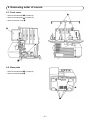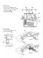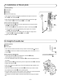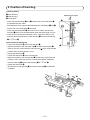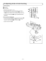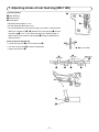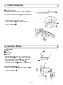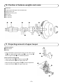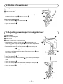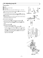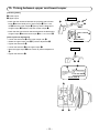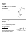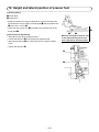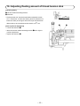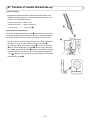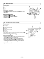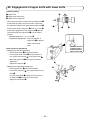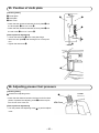
1
2-Needle, 4-Thread Overlock Sewing Machine
MO-114D/104D
SERVICE MANUAL
MO-114D
MO-104D
CONTENTS
1. Specifications...................................................................................................1
2. Removing order of covers...............................................................................2
2-1. Front cover....................................................................................................................2
2-2. Base plate......................................................................................................................2
2-3. Rear cover.....................................................................................................................3
2-4. Cloth plate.....................................................................................................................3
3. Installation of throat plate...............................................................................4
4. Height of needle bar.........................................................................................4
5. Position of feed dog.........................................................................................5
6. Adjusting stroke of main feed dog.................................................................6
7. Adjusting stroke of sub feed dog (MO-114D).................................................7
8. Height of feed dog............................................................................................8
9. Feed dog timing................................................................................................8
10. Position of balance weights and cams..........................................................9
11. Projecting amount of upper looper.................................................................9
12. Radius of lower looper...................................................................................10
13. Adjusting lower looper thread guide lever...................................................10
14. Adjusting loop lift...........................................................................................11
15. Timing between upper and lower looper......................................................12
16. Installation of needle guards.........................................................................13
17. Position of upper looper thread take-up......................................................13
18. Height and lateral position of presser foot..................................................14
19. Adjusting floating amount of thread tension disk.......................................15
20. Thread tension controller..............................................................................16
21. Position of needle thread take-up.................................................................17
22. Belt tension.....................................................................................................18
23. Position of lower knife...................................................................................18
24. Engagement of upper knife with lower knife...............................................19
25. Position of cloth plate....................................................................................20
26. Adjusting presser foot pressure...................................................................20
CAUTION:
Be sure to observe the following to protect against a fire, electrical shock, injury or damaged components.
*Be sure to unplug the machine before disassembly, assembly or adjustment of the machine.
*Be sure to use the proper genuine parts when changing any of the machine parts.
1. Specifications
No.
Items
Description
1
Number of needle and threads
2-needle and 4-thread (with differential feed)
2
Needle
130/705H No. 70/80 (10/12)
3
Overedge width
2-needle, 4-thread : 6 mm
1-needle, 3-thread : 4 mm
Roll hemming : 2 mm
4
Stitch length
1.0 to 4.0 mm (standard : 2.5 mm)
5
Differential feed ratio
1 : 0.5 to 0.7 (standard : 1.2 ± 0.3)
6
Needle bar stroke
27 mm
7
Feed dog height
1.3 mm (standard)
8
Presser foot height
5 mm (standard), 7 mm (two step presser foot)
9
Power consumption
105 W
10
Motor (built-in)
Input : 90 W, Output : 42 W (120 V)
Input : 90 W, Output : 44 W (240 V)
11
Light
15 W screw type (120 V)
10 W screw type (240 V)
12
Power switch
2-step rocker switch
13
Sewing speed
Max. 1,500 sti/min (SPM)
14
Driving system
Timing belt. Machine rotates in the forward (normal) direction
15
Machine size
315 (W) × 290 (D) × 290 (H)
16
Machine weight
7.0 kg
17
Foot control
Electronic type
–1–
2. Removing order of covers
2-1. Front cover
2
○ Remove the setscrews 1 (3 locations).
○ Remove the setscrews 2 (2 locations).
○ Remove the front cover A.
A
1
2-2. Base plate
○ Remove the setscrews 3 (4 locations).
○ Remove the base plate B.
B
3
–2–
2-3. Rear cover
4
○ Remove the setscrews 4 (2 locations).
○ Remove the presser foot adjusting screw 5.
○ Raise the presser foot lifting lever 6.
○ Open the cloth plate D.
○ Remove the rear cover C.
5
C
6
D
2-4. Cloth plate
D
○ Remove the setscrews 7 (2 locations).
○ Remove the cloth plate D.
<MO-114D>
7
D
<MO-104D>
–3–
3. Installation of throat plate
[Checking items]
1 Throat plate
2 Setscrew
3 Feed dog
4 Center of needle entry
A
* Check that all needles are laterally equidistant with respect to the needle slot A in the throat plate 1.
* Check that the distance between the needle center and the front edge
of the needle slot A in the throat plate 1 is 1.4 mm B.
[How to perform adjustment]
○ Loosen the setscrew 2. Carry out the adjustment by moving the throat
plate 1 as described below:
a) The feed dog 3 teeth are parallel to the slots in the throat plate 1.
b) The needles are spaced equidistantly with respect to the needle
slot A in the throat plate 1.
c) The distance between the needle center and the front edge of the
needle slot A in the throat plate 1 is 1.4 mm B.
○ Tighten the setscrews 2.
4
B
3
1
2
4. Height of needle bar
[Checking items]
1 Needle
2 Throat plate
1
* Check that the distance between the top surface of throat plate 2 and the
needle 1 point with the needle bar at the highest point of its stroke is 10.1 ±
0.15 mm A.
A
[How to perform adjustment]
○ Loosen the setscrew B of the needle bar connection C slightly.
(The needle bar should not slip down.)
○ Turn the handwheel to allow the needle bar D to reach the highest point of
its stroke.
○ Move needle bar D up and down by hand to adjust dimension A is obtained.
○ Tighten the setscrew B.
* Check the position of needle entry of the left needle and right needle to the
throat plate 2.
* Check the clearance between the needle 1 and the looper, and the clearance between the needle 1 and the needle guard.
* The right needle is at the center position of the needle bar, but the left needle
is offset on the left side from the center of the needle bar.
The position of the left needle moves back and forth by turning the needle
bar.
–4–
2
C
D
B
5. Position of feed dog
[Checking items]
1 Main feed dog
2 Sub feed dog
3 Throat plate
Clearances are equal.
1
* Check that the feed dogs (1 and 2) and the slot in the throat plate 3
are parallel with each other.
* The clearances of the right and left side between the feed dogs (1 and 2)
and the slot in the throat plate 3 are equal.
* Check that the throat plate 3 does not come in contact with the main
feed dog 1 at the most receded position when the stitch length is 4 mm.
* Check at the most-advanced position in max. main feed and min. sub
feed the clearance between the main feed dog 1 and the sub-feed dog
B
C
2
2 is 1 +0.4
-0.5 mm C.
[How to perform adjustment]
○ Loosen the setscrews D of the main feed dog 1.
○ Adjust the position of the main feed dog 1 so that the throat plate 3
does not come in contact with the main feed dog 1 at the most receded
position when the stitch length is 4 mm.
○ Tighten the setscrews D.
○ Loosen the setscrews E of the sub feed dog.
○ Adjust the position of the sub feed dog 2 so that at the most-advanced
position in max. main feed and min. sub feed the clearance between
3
the main feed dog 1 and the sub-feed dog 2 is 1 +0.4
-0.5 mm C.
○ Tighten the setscrews E.
○ Check that the main feed dog 1 and the sub feed dog 2 are attached
in parallel.
D
E
–5–
6. Adjusting stroke of main feed dog
[Checking items]
1 Feed dog
2 Throat plate
* Adjust the stitch length to 1 mm.
* Turn the handwheel to move the feed dog up and down.
Check that the moving amount of feed dog 1 is 1.2 ± 0.2
mm A when the teeth tip of the feed dog is aligned with the
top surface of throat plate 2 during its upward/downward
movement.
A
1
[How to perform adjustment]
○ Loosen the setscrews D of the horizontal feed regulator C.
○ Turn the horizontal feed regulator C so that the moving
amount of main feed dog 1 is 1.2 ± 0.2 mm A.
○ Tighten the setscrews D.
2
D
C
–6–
7. Adjusting stroke of sub feed dog (MO-114D)
[Checking items]
1 Main feed dog
2 Sub feed dog
3 Throat plate
3
1
2
* Adjust the stitch length to 4 mm.
* Set the differential feed ratio at "N".
* Turn the handwheel to move the feed dog up and down. Check that the
difference of clearance (A - A') between the main feed dog 1 and the
sub feed dog 2 is 0 ± 0.1 mm when the teeth tip of feed dog teeth is
aligned with the top surface of throat plate 3 during its upward/downward movement.
[How to perform adjustment]
○ Loosen the setscrew C of the eccentric stud D.
○ Turn the eccentric stud D to perform adjustment.
○ Tighten the setscrew C.
A'
A
A - A' = 0 ± 0.1 mm
A
A'
Same line
3
1
D
C
–7–
2
1
2
8. Height of feed dog
[Checking items]
1 Front end of feed dog
* Adjust the stitch length to 2.5 mm. Bring the feed dog to
its highest position. At this time, check that the height of
front end 1 of feed dog with respect to the top surface of
the throat plate is 1.3 ± 0.1 mm A.
1
A
[How to perform adjustment]
○ Set the feed dog in its highest position.
○ Loosen the setscrew C of the eccentric stud D.
○ Turn the eccentric stud D to perform adjustment.
○ Tighten the setscrew C.
C
D
9. Feed dog timing
[Checking items]
1 Needle
2 Throat plate
3 Feed dog
1
2
* Adjust the stitch length to 2.5 mm. When the feed dog
3 and the needle 1 go up, check that the tip of needle
1 and the teeth tip of feed dog 3 are simultaneously
aligned with the top surface of throat plate 2.
* The position of the needle 1 shall be ± 0.2 mm from the
top surface of throat plate 2.
3
A
[How to perform adjustment]
○ Loosen the setscrews A of the feed eccentric cam B.
○ Turn the feed eccentric cam B to perform adjustment.
○ Tighten the setscrews A.
B
–8–
10. Position of balance weights and cams
1 Feed cam
2 Lower looper and upper knife combined cam
3 Upper looper cam
4 Needle bar driving cam
5 Main shaft
6 1st setscrew
7 1st setscrew
5
1
2
3
4
7
6
11. Projecting amount of upper looper
[Checking items]
1 Upper looper
2 Needle
A
* Check that distance (projecting amount) from the center of needle 2 to the blade point of upper looper 1 is 4.0 ± 0.2 mm A
when the upper looper 1 is in its leftmost position.
[How to perform adjustment]
○ Set the upper looper 1 in its leftmost position B.
○ Loosen the setscrew C of the upper looper arm.
○ Move the upper looper siding shaft D to perform adjustment.
○ Tighten the setscrew C of the upper looper arm.
1
2
B
D
C
–9–
[Checking items]
1 Setscrew of lower looper
2 Lower looper shaft
3 Lower looper
A
12. Radius of lower looper
.15
mm
3
* Check that the distance from the center of lower looper shaft 2 to the
blade point of lower looper 3 is 66.0 ± 0.15 mm A.
.0
±0
1
66
[How to perform adjustment]
○ Loosen the setscrew 1 of the lower looper 3.
○ Move the lower looper 3 up or down to perform adjustment.
○ Tighten the setscrews 1.
2
13. Adjusting lower looper thread guide lever
[Checking items]
1 Lower looper thread guide
2 Lower looper
3 Groove of lower looper thread guide lever
To align end faces with each other
2
* Check that the top surface of lower looper 2 is aligned with the top
surface of the lower looper thread guide 1 when the lower looper thread
guide lever E is in its highest position.
* Check that the lower looper thread guide lever E is lowered by hand
when the lower looper 2 is in its right most end of its stroke, and the lower looper thread guide lever E automatically returns to its home position
by turning the handwheel before the blade point of lower looper 2 crosses the center of needle.
3
1
A
E
D
[How to perform adjustment]
○ Loosen the setscrews A.
○ Move the lower looper thread guide arm D up or down to perform adjustment.
○ Tighten the setscrews A.
○ Loosen the setscrew B of the lower looper thread guide lever plate C.
○ Move the plate C up or down to perform adjustment.
○ Tighten the setscrew B.
E
C
– 10 –
B
14. Adjusting loop lift
* Check that the clearance between the needle 1 and the blade point
2 of lower looper is 0.01 to 0.1 mm E.
* Turn the handwheel and check that the blade point 2 of lower looper meets with the left side of gauge needle 4 when the lower looper
3 goes and back.
* The difference between the vertical positions when the lower looper
goes and back shall be 0.2 mm or less.
[How to perform adjustment]
○ Loosen the setscrews C of the lower looper support arm D.
○ Move the lower looper support arm D back or forth to adjust the
clearance between the needle 1 and the blade point 2 of lower
looper.
○ Tighten the setscrews C.
○ Adjusting the lower looper cam timing.
• Loosen the setscrews A of the lower looper cam B.
• Check the position of the blade point 2 of lower looper and the
gauge needle 4 while turning the lower looper cam B. Change
the position of the cam little by little so that the left side of gauge
needle 4 can meet with the blade point 2 of lower looper on
both ways of going and back.
• Tighten the setscrews A.
1
32.3 mm
[Checking items]
1 Needle
2 Blade point of lower looper
3 Lower looper
4 Gauge needle (Cut the top end of needle for use. L = 32.3 mm)
2
E
Gauge needle
4
3
2
A
B
A
C D
– 11 –
C
15. Timing between upper and lower looper
[Checking items]
1 Lower looper
2 Upper looper
Rear view
* Check that the clearance between the projecting part of lower
looper 1 and the blade point of upper looper 2 is 0.5 ± 0.2
mm A when the upper looper 2 goes up and the blade point
of upper looper 2 meets the top end of lower looper 1.
* Check that the front-to-back clearance between the blade point
of upper looper 2 and the lower looper 1 is 0.1 to 0.3 mm B.
2
C
F
A
1
0.5 ± 0.2 mm A
[How to perform adjustment]
○ Loosen the setscrews E of the upper looper cam D.
○ Rotate the upper looper cam D to perform adjustment A.
○ Tighten the setscrews E.
○ Loosen the setscrew C of the upper looper 2.
○ Move the upper looper 2 front or back to perform adjustment
1
2
Arrow view F
Rear view
G
B.
○ Tighten the setscrew C.
2
1
1
2
0.1 to 0.3 mm B
Arrow view G
E
E
– 12 –
D
16. Installation of needle guards
[Checking items]
1 Needle guard
2 Needle
* Check that the clearance between the needle 2 and the front
needle guard 1 is 0 to 0.1 mm A when the needle bar is at the
lowest position of the stroke.
[How to perform adjustment]
○ Set the needle bar in its lowest position of the stroke.
○ Loosen the setscrews B of the front needle guard 1.
○ Move the front needle guard 1 to perform adjustment.
○ Tighten the setscrews B.
2
0t
o0
.1 m
m
A
1
B
17. Position of upper looper thread take-up
[Checking items]
1 Upper looper thread take-up
2 Setscrew
3 Looper cover hinge
* Check that the distance between the lower end of upper looper
thread take-up 1 and the top surface of looper cover hinge 3
is the dimension A (described below) when the upper looper is
at the lowest position of the stroke.
1
Dimension A
2
MO-114D 6.0 ± 0.5 mm
MO-104D 7.5 ± 0.5 mm
3
[How to perform adjustment]
○ Set the upper looper in its lowest position of the stroke.
○ Loosen the setscrew 2.
○ Adjust the position of upper looper thread take-up 1.
○ Tighten the setscrew 2.
– 13 –
A
18. Height and lateral position of presser foot
[Checking items]
1 Throat plate
2 Presser foot
* Raise the presser foot using the lifting lever, and check that the distance between the top surface of throat plate 1 and the presser foot
2 sole is 5.0 ± 0.2 mm A.
* Check that the presser foot 2 is parallel to the feed dog slot in the
throat plate 1.
[How to perform adjustment]
○ Raise the presser foot by lifting the lever.
○ Loosen the setscrew B of the presser bar guide bracket.
○ Move the presser bar C up or down and turn it to perform adjustment.
○ Tighten the setscrew B.
A
2
1
Measure the height of presser foot
in the state that the presser foot
sole is parallel to the throat plate.
B
C
– 14 –
19. Adjusting floating amount of thread tension disk
[Checking items]
1 Tension release actuating bracket
2 Setscrew
0.9 +0.3
-0.2 mm
* Lift the presser foot. Set the thread tension adjustment knob
at "4". At this time, check that a floating amount (clearance between two disks) of the upper and lower looper thread tension
disks at the top end of thread tension shaft is 0.9 +0.3
-0.2 mm.
1
[How to perform adjustment]
○ Loosen the setscrew 2.
○ Move the tension release actuating bracket 1 left or right to
perform adjustment.
○ Tighten the setscrew 2.
– 15 –
2
20. Thread tension controller
[Checking items]
* Using Saba C 120, check that the thread tensions are the numeric values shown below. (Scale mark on the knob "4")
Turn up the knob to the scale mark on “9” and then return to
the scale mark on “4” to check the thread tensions.
• Left-hand needle thread-------- 0.29 ± 0.05 N (30 ± 5 g)
• Right-hand needle thread------ 0.14 ± 0.03 N (14 ± 3 g)
• Upper looper thread------------- 0.12 ± 0.02 N (12 ± 2 g)
• Lower looper thread------------- 0.24 ± 0.03 N (24 ± 3 g)
2
[How to perform adjustment]
4
(For example) when you want to strengthen a standard thread
tension,
○ When you want to strengthen the thread tension by the
amount of A, move the knob to its position.
○ Insert the small-screwdriver into the thread tension controller
from the thread path slot (slit) of the front cover and put it on
the shelf 1 inside the front cover.
○ Push the flange part 2 of the thread tension pulley in the
direction of the arrow using the tip of the small-screwdriver
and release the engagement of the thread tension drive gear
3 with the intermediate gear 4.
○ In this state, return the knob to the standard scale mark on “4.”
○ When you stop pushing the small-screwdriver, the thread
tension drive gear 3 engages with the intermediate gear 4
in the original state.
(Caution)After you stop pushing the small-screwdriver,
check that they engage with each other properly
by moving the thread tension knob up and down
just slightly.
– 16 –
1
5
A
3
21. Position of needle thread take-up
[Checking items]
* To adjust the needle thread loop, adjust the vertical position of the
needle thread take-up guide so that a stitch skipping may not occur
at the time of double fabric sewing.
• Thread to be used------ Saba C 120
• Fabric to be used------- Denim 10oz 2-6-2
• Loop amount------------- 1.5 to 2 mm A
A
[How to perform adjustment]
Mount the needle thread take-up guide C with reference to the following position and adjust the clearance between the needle thread takeup and the thread in accordance with the illustrations shown below.
B
C
○ During movement of the needle thread take-up, it shall not interfere
with the front cover and the needle thread take-up guide C .
○ To adjust the needle thread take-up guide C , loosen the setscrew
B of the needle thread take-up guide C and move it up and down.
○ The needle thread take-up guide C shall be mounted at the position
where a washer for the setscrew part of the needle thread take-up
guide C is aligned with the lower end of the slit eyelet of the needle
thread take-up guide C.
To be aligned
– 17 –
22. Belt tension
[Checking items]
1 Belt
2 Motor
3 Nuts
1
3
A
2
* Sewing speed : 1,500 sti/min
* The belt 1 should slacken approx. 3 to 4 mm A under a 1.96 N
(200 g) load.
[How to perform adjustment]
○ Loosen the nuts 3 of the motor 2.
○ Move the motor 2 to perform adjustment.
○ Tighten the nuts 3.
23. Position of lower knife
[Checking items]
1 Throat plate
2 Lower knife presser plate
3 Setscrew
4 Lower knife support plate
5 Setscrew
6 Lower knife
1
A
2
6
* Check that the distance between the top surface of throat plate 1
and the lower knife 6 is 0 to 0.3 mm A.
[How to perform adjustment]
○ Loosen the setscrew 3 of the lower knife presser plate and the
setscrew 5 of the lower knife support plate.
○ Move the lower knife 6 up or down to perform adjustment.
○ Turn the lower knife support plate 4 to be brought into close
contact with the lower end of lower knife 6. Then, tighten the
setscrew 5.
○ Tighten the setscrew 3.
– 18 –
3
5
24. Engagement of upper knife with lower knife
[Checking items]
1 Upper knife
2 Upper knife rocking arm
3 Upper knife turning knob
A
F
* When the lower knife is contact with the upper knife 1
at the leftmost position of the lower knife, check that
the clearance between the upper knife turning knob 3
and the upper knife rocking arm 2 is 0.5 to 1.0 mm A.
* Check the engagement of the upper knife 1 with the
lower knife when the upper knife 1 is in the lowest
position.
• Vertical engagement : 1 to 1.5 mm B
• Longitudinal engagement : The rear end face of
upper knife 1 is aligned
with the tip of lower
knife.
1
– 19 –
3
B
The rear end face
of upper knife is
aligned with the
tip of lower knife.
[How to perform adjustment]
• Adjusting the vertical engagement
○ Set the upper knife 1 in its lowest position.
○ Fix the upper knife holder F using a spanner 11
mm, loosen the setscrew D of the upper knife 1.
○ Move the upper knife 1 up or down to perform
adjustment.
○ Tighten the setscrew D.
• Adjusting the longitudinal engagement
○ Set the upper knife 1 in its lowest position.
○ Loosen the setscrews E of the upper knife turning
knob 3.
○ Turn the upper knife 1 to align the rear end face
of upper knife 1 and the tip of lower knife.
○ Tighten the setscrews E.
2
H
D
E
25. Position of cloth plate
[Checking items]
1 Throat plate
2 Cloth plate
3 Rear cover
B
3
2
* Check that the clearance between the cloth plate 2 and
the throat plate 1 is 0 to 0.3 mm A.
* Check that the clearance between the cloth plate 2 and
the rear cover 3 is 0.5 to 1.5 mm B.
1
[How to perform adjustment]
○ Loosen the setscrews C of the cloth plate hinge.
○ Move the cloth plate 2 with the hinge in its correct position.
○ Tighten the setscrews C.
A
A
C
26. Adjusting presser foot pressure
[Checking items]
1 Presser foot adjusting screw
1
* Check that the distance between the lower end of knurled
portion of presser foot adjusting screw 1 and the top surface of rear cover is 0.5 mm.
[How to perform adjustment]
○ Turn the presser foot adjusting screw 1 to perform adjustment.
– 20 –
Rear cover
0.5 mm
HOUSEHOLD SEWING MACHINERY
BUSINESS UNIT
2-11-1, TSURUMAKI, TAMA-SHI,
TOKYO, 206-8551, JAPAN
PHONE : (81)42-357-2341
FAX : (81)42-357-2380
http://www.juki.com
Copyright C 2015 JUKI CORPORATION
All rights reserved throughout the world.
40167630
2015/09