1
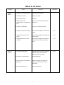
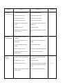
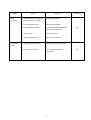
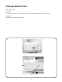
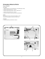
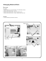
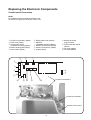
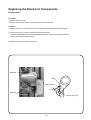
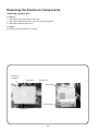
SERVICE MANUAL
2160DC, DXL603
INDEX
What to do when .............................................................................................................................. 1 - 3
Changing External Parts
Face Cover ............................................................................................................................................. 4
Free-arm Cover ...................................................................................................................................... 5
Front Cover ....................................................................................................................................... 6 - 7
RearF Cover ........................................................................................................................................... 8
Mechanical Adjustment
Presser Bar Height ................................................................................................................................. 9
Needle Drop Position ........................................................................................................................... 10
Adjustment of Hook Timing .................................................................................................................. 11
Adjustment of Needle Bar Height ......................................................................................................... 12
Clearance between Needle and Tip of Hook Rotary ............................................................................ 13
Feed Dog Height .................................................................................................................................. 14
Feed Dog Adjustment (Only for model 3160QDC) ............................................................................... 15
Top Tension .......................................................................................................................................... 16
Replacing the Electronic Components
Circuit Board-A connection .................................................................................................................. 17
Self-diagnostic Test ......................................................................................................................... 18-22
Circuit Board-A ................................................................................................................................ 23-24
Driving Motor ........................................................................................................................................ 25
Switching regulator Unit ....................................................................................................................... 26
Adjusting Buttonhole Lever Position ..................................................................................................... 27
Parts List ........................................................................................................................................ 29-43
What to do when
Condition
1. Skipping
Stitches
2. Fabric not
moving
Cause
How to fix
Reference
1. Needle is not inserted properly.
Insert the needle properly.
2. Needle is bent or worn.
Change the needle.
3. Incorrectly threaded.
Rethread.
4.Needle or thread are
inappropriate for the fabric being
sewn.
Use the recommended sewing needle
and thread.
5. Sewing on stretch fabric.
Use a HA x #11 blue tip needle.
6. Inappropriate needle bar height.
See mechanical adjustment “Needle bar
height”.
P. 12
7. Inappropriate needle to hook
timing.
See mechanical adjustment “Adjustment
of hook timing”.
P. 11
8. Inappropriate needle to hook
clearance.
See mechanical adjustment “Clearance
between needle and tip of the rotary
hook”.
P. 13
1. Incorrect feed dog height.
Adjust the presser bar level to make the
pressure stronger. See mechanical
adjustment “Feed dog height”.
P. 14
2. Feed dog is in down position.
Raise the feed dog.
3.Thread on bottom side of fabric is
jammed up.
Make sure to bring both needle and
bobbin threads under the foot when
start sewing.
4. Feed dog teeth are worn.
Change the feed dog.
1
Condition
3. Breaking
upper thread.
4. Breaking
bobbin thread.
5. Needle
breakes
Cause
How to Fix
1. Initial sewing speed is too fast.
Start with medium speed.
2. Thread path is incorrect.
Use the proper thread path.
3. Needle is bent or dull.
Replace with a new needle.
4. Top tension is too strong.
Adjust top tension correctly.
5. Needle size is inappropriate for
fabric.
Use appropriate needle for fabric and
thread in use.
6. Needle eye is worn.
Change the needle.
7. Needle hole in needle plate is
worn or burred.
Repair the hole or replace the needle
plate.
1. Bobbin holder is incorrectly
threaded.
Set the bobbin thread correctly.
2. Too much thread is wound on
the bobbin.
Adjust the position of bobbin winder
stopper.
3. Lint is stuck inside the bobbin
holder.
Clean the bobbin holder.
4. Thread quality is too low.
Change to a high quality sewing thread.
5. Thread is jamming around the
bobbin holder.
Clear out the jamming thread.
1. Needle is hitting the needle plate.
See mechanical adjustment “Needle
drop position”.
2. Needle is bent or worn.
Change the needle.
3. Needle is hitting the hook.
See mechanical adjustment “Clearance
between needle and tiip of the rotary
hook”.
4. Fabric is being pulled too strongly
while sewing.
Guide the fabric gently while sewing.
2
Reference
P. 10
P. 13
Condition
6. Noisy
operation
7. Deformation
pattern
Cause
How to fix
1. Backlash between hook gear and
lower shaft gear is too great.
Eliminate the backlash.
2. Lower shaft gear is loose.
Eliminate the looseness.
3. Inappropriatte belt tension.
See part removal and replacement
“driving motor (DC motor)”.
4. Not enough oil.
Oil all moving parts.
5. Upper shaft gear is loose.
Eliminate the looseness.
1. Inappropriate feed balance.
Adjust the feed balancing screw.
2. Top tension is too strong.
See mechanical adjustment
“Top tension”.
3
Reference
P. 25
P. 16
Changing External Parts
Face cover
To remove:
1. Loosen the setscrew q and lift the face cover to disengage the rib on the inside. Remove the face cover w.
To attach:
2. Follow the above procedures in reverse.
q
w
4
Changing External Parts
Free-arm cover
To remove:
1. Loosen the setscrew q and w. Move the free-arm cover to the left. Remove the free-arm cover.
To attach:
Follow the above procedures in reverse.
q
e
w
5
Changing External Parts
Front cover (1)
To remove:
1. Remove the face cover and free-arm cover (See page 4 and 5).
2. Remove the setscrews (A) q (2 pcs.).
3. Remove the setscrews (B) w (5 pcs.), back cover e.
4. Remove the setscrews (C) r (2 pcs.).
5. Disconnect all the connectors from the circuit board A.
NOTE:
Do not disconnect the connectors by pulling on cord.
To disconnect, grasp the connector, not the cord.
To attach:
6. Follow the above procedures in reverse.
q
w
e
w
r
6
w
r
Changing External Parts
Front cover (2)
4. Disengage the front cover and rear cover hooks.
5. Remove the front cover.
To attach:
Follow the above procedures in reverse.
7
Changing External Parts
Rear cover
To remove:
1. Remove the face cover and free-arm cover (See page 4 and 5).
2. Remove the setscrews (A) q (4 pcs.).
3. Remove the setscrews (B) w (5 pcs.) and back cover.
4. Remove the setscrews (C) e (2 pcs.). Remove the rear cover.
To attach:
5. Follow the above procedures in reverse.
q
Back cover
w
w
Rear cover
q
e
8
Mechanical Adjustment
Presser bar height
The distance between the bottom of the presser foot in up position and the needle plate should be 6.0 mm.
1. Remove the face plate and needle.
2. Lower the feed dog below the needle plate. Place a block 6 mm thick under the presser foot and lower the
presser foot lifter w.
3. Loosen the setscrew q. Raise the presser foot lifter and tighten the setscrew q firmly.
Attach the needle and face plate.
NOTE:
Make sure that the presser foot should be parallel to the feed dog slots e in the needle plate.
q
w
6.0mm
Presser foot should be
parallel to the feed dog slots.
e
9
Mechanical Adjustment
Needle drop position
Set the stitch pattern to “ ”. The standard needle drop position should be at center of the needle plate hole q.
Select zigzag stitch “ ”, and set the stitch width at “5.0”. The clearance between the needle and the edge of
the needle hole in the needle plate should be at least 0.2 mm on either side. If not, adjust as follows:
1. Turn the power switch off. Remove the face cover. (See page 4.)
2. Loosen the hexagonal socket screw 3 x 4 w. Adjust the needle drop position by turning the eccentric pin e.
The direction of eccentric pin should be as shown in Fig. 1.
3. Attach the face cover.
NOTE:
Check the hook timing after this adjustment.
q
Fig. 1
0.2 mm
or more
0.2 mm
or more
A=B
10
Mechanical Adjustment
Adjustment of hook timing
The amount of ascending travel of the needle bar from its lowest position to the position (
the rotary hook exactly meets the right side of the needle should be 3.25 to 3.55 mm.
) where the tip of
1. Remove the needle plate and bobbin holder.
2. Turn the power switch on.
3. Select the pattern
(left position). Set the zigzag width at 0.
4. Remove the free-arm cover.
Turn the handwheel toward you to lower the needle at its lowest position.
5. Loosen the hexagonal socket screw w (2 pcs.).
6. Move the needle bar 3.4 mm from the lowest position.
7. Turn the lower shaft gear until the tip of hook meets the right side of the needle while holding the handwheel.
8. Tighten the hexagonal socket screw w (2 pcs.).
9. Attach the free-arm cover, bobbin holder and needle plate.
Needle plate
w
Bobbin holder
Lower shaft gear
w
Tip of hook meets the
right side of the needle
Left position (
(#14)
)
3.25 – 3.55mm
Lowest needle position
11
Mechanical Adjustment
Adjustment of needle bar height
Before proceeding with this adjustment, check the hook timing (refer to page 11). The distance between the
upper edge of the needle eye and the tip of the hook should be in the range of 1.6 to 2.0 mm when the tip of the
hook timing meets right side of the needle in the left needle position ( ) as the needle ascends from its lowest
position.
1. Remove the needle plate, bobbin holder and face plate.
2. Turn the power switch on.
3. Select the pattern (left position). Set the zigzag width at 0.
4. Turn the handwheel toward you until the tip of hook meets the right side of the needle.
5. Loosen the hexagonal socket screw q.
6. Move the needle bar to adjust the needle bar height, and tighten the hexagonal socket screw q.
Be careful not to turn the needle bar.
7. Attach the bobbin holder, needle plate and face cover.
Needle plate
Hexagonal socket screw
Bobbin holder
Needle setting groove
Tip of hook meets the right side of the needle
Left position (
(#14)
Hook race
)
1.6 – 2.0 mm
Upper edge of needle hole
Hook race (unit)
12
Mechanical Adjustment
Clearance between needle and tip of the rotary hook
* The clearance between the needle and the point of hook should be –0.1 to +0.05 mm.
Adjustment procedure:
1. Remove the needle plate and bobbin holder. Attach the master needle. Turn the power switch on and set the
zigzag width at maximum.
2. Remove the face cover.
3. Loosen the setscrew A (2 pcs.).
4. Turn the handwheel toward you. Adjust the clearance between the needle and the tip of the rotarty hook, by
moving the hook base plate up or down, to within –0.1 to +0.05 mm at the left and right needle position.
5. Tighten the setscrew A (2 pcs.).
6. Attach the face cover. Remove the master needle. Attach the bobbin holder and needle pate.
7. Check the clearance between the needle and the edge of the needle hole in the needle plate (see page 10).
Needle plate
Needle bar supporter
adjusting plate
Bobbin holder
Tip of hook
–0.1 to +0.05 mm
13
Hexagonal socket screw (A)
Mechanical Adjustment
Feed dog height
The highest position of the feed dog should be between 0.80 and 0.90 mm from the surface of the needle plate.
1. Lower the presser foot and turn the power switch on.
2. Turn the handwheel toward you to set the feed dog at the highest position.
3. Remove the free-arm cover.
4. Loosen the setscrew (A) q and nut w.
5. Adjust the feed dog height by turning the adjusting screw e. The highest position of the feed dog should be
between 0.80 and 0.90 from the surface of the needle plate.
6. Tighten the nut w and setscrew (A) q.
7. Attach the free-arm cover.
Presser foot
0.80 – 0.90mm
Feed dog
Surface of the needle plate
q
A
e
w
q
14
B
Mechanical Adjustment
Feed dog adjustment (Only for model 3160QDC)
The highest position of the feed dog should be parallel to the surface of the needle plate.
If not, adjust as follows.
1. Use a hexagonal socket screw (4 x 6).
Insert the screw to the hole B. Tighten the hexagonal socket screw as far as it goes.
2. Loosen the setscrew C.(left screw)
3. Turn hexagonal socket screw to adjust the feed dog (should be parallel to the surface of the needle plate).
4. Tighten the setscrew C.(left screw)
5. Loosen the hexagonal socket screw and remove it.
Hexagonal socket scrw 4 x 6
Setscrew C
(left screw)
Setscrew C
15
Hole B
Mechanical Adjustment
Top tension
The top tension should be between 65 and 80g when pulling the thread q up in the direction of C.
* Use polyester sewing thread #50 (White).
* If it is not within the above limit, adjust as follows.
1. Set the tension dial “Auto”.
2. Remove the cover.
3. Lower the presser foot.
• If the top tension is too loose, turn the lead screw in the direction (A).
• If the top tension is too tight, turn the lead screw in the direction (B).
4. Check the top tension and attach the cover.
Cover
Pull the thread at the speed of 110
mm/sec in the direction of arrow
White polyester thread size 50
16
Replacing the Electronic Components
Circuit board-A Connection
NOTE:
Do not disconnect the connectors by pulling on cord.
To disconnect, grasp the connector, not the cord.
q Printed circuit board P (Black)
w Feed motor (White)
e Thread cutter motor
(3160QDC exclusive) (White)
r Bobbin winding switch (Blue)
t Power switch (White)
t
y
y Zigzag width motor (Green)
u Solenoid
(3160QDC exclusive) (Black)
i Printed circuit board F (White)
o Printed circuit board L (White)
!0 Program (Red)
!1 Buttonhole sensor
program (Red)
!2 Presser foot lifter switch
(Green)
!3 DC motor (White)
!4 Controller (Black)
u
r
e
w
i
o
q
!4
!3 !2
!1
Printed circuit board A
!0
Printed circuit board F
Printed circuit board L
17
Self-diagnostic Test
Preparation:
1. Turn the power switch off.
2. Move the bobbin winder spindle to the left.
3. Raise the feed dog.
4. Set the speed control lever to the left.
5. Remove the presser foot and raise the presser foot lifter.
6. Turn the hand wheel toward you to raise the needle to its highest position.
Notes:
• Be careful: the sewing machine may start running in its own while in test mode.
• Turn off the power switch before replacing any parts.
• Repeat the diagnostic test until the problem has been resolved.
• You can skip steps in the diagnostic procedure and go directly to the test you want to perform.
(Enter self-diagnostic mode, then select the step number of the diagnostic test you require by
pressing the start/stop button)
To begin:
Turn on the switch, if any of the following problems occur, take the recommended actions in the order
they are shown.
1. The machine does not respond when the power switch is turned on:
• Check each connector connection
• Replace the machine socket
• Replace the Switching regulator.
• Replace the A-board
2. The sewing machine lamp does not light up:
• Replace the light bulb
• Replace the A-board
To enter self-diagnostic mode:
Turn the power switch on
while simultaneously
pressing needle up/down
button and the locking
stitch button.
The LCD display will
indicate “01”.
18
Press the start/stop button to
enter the self-diagnostic mode.
Self-diagnostic Test
Step and items
to check
01)
Function of
LCD, buzzer
and lamp
Procedure
Correct Condition
Turn on the power switch while
simultaneously pressing the start/stop
button and locking stitch button.
Press the start/stop button.
If the result is correct condition, press
the start/stop button to proceed the
next step.
If the result is defective condition,
press the reverse stitch button to
proceed the next step.
02)
Button
Sewing lamp and LCD backlight lits.
LCD displays “01”.
Press buttons 1– 7.
1
3
Buzzer sounds when button is pressed.
Button number is displayed when the
button is pressed.
2
7 6
Buzzer does not sound.
LCD does not display the
number correctly.
–REMEDY–
Replace the circuit board A.
Replace the circuit board F.
5
If the result is correct condition, press
the start/stop button to proceed the
next step.
If the result is defective condition,
press the reverse stitch button to
proceed the next step.
03)
Buttonhole
Sensor
Sewing lamp does not lit.
LCD backlight does not lit.
LCD does not display “01”.
Buzzer does not sound.
LCD does not turned on.
LCD does not display any
symbols or not in order.
Buzzer sounds.
LCD displays symbols and numbers in order.
LCD repeats displaying after all symbols and –REMEDY–
Replace the circuit board A.
numbers are shown.
LCD displays “SC 02”.
4
Defective Condition
LCD displays “S3” when button 1 is pressed.
LCD displays “S4” when button 2 is pressed.
LCD displays “S5” when button 3 is pressed.
LCD displays “S6” when button 4 is pressed.
LCD displays “S7” when button 5 is pressed.
LCD displays “S8” when button 6 is pressed.
LCD displays “S9” when button 7 is pressed.
Lower the buttonhole lever.
Movethebuttonholelever back and
forth.
LCD displays “SC 03”.
If the result is correct condition, press
the start/stop button to proceed the
next step.
When the buttonhole lever is pushed,
buzzer sounds and LCD displays BH
symbol.
When the buttonhole lever is pulled, buzzer
sounds and LCD displays BH symbol.
Buzzer does not sound.
BH symbol does not appear.
–REMEDY–
Replace the circuit board A.
Replace the circuit board F.
If the result is defective condition,
press the reverse stitch button to
proceed the next step.
04)
Bobbin winder
switch
Move the bobbin winder spindle to the
right.
Return it to the left.
If the result is correct condition, press
the start/stop button to proceed the
next step.
If the result is defective condition,
press the reverse stitch button to
proceed the next step.
BH symbol
LCD displays "SC 04".
Buzzer does not sound.
When the bobbin winder spindle is moved to Bobbin symbol is not
displayed.
the left, buzzer sounds.
When the bobbin winder spindle is moved to –REMEDY–
the right, buzzer sounds and LCD displays
Replace the circuit board A.
the bobbin symbol.
Replace the circuit board F.
Bobbin symbol
19
Self-diagnostic Test
Step and
items to check
05)
Presser foot
lifter switch
Procedure
Correct Condition
Raise or lower the preser foot lifter.
LCD displays “SC 05”.
If the result is correct condition, press
the start/stop button to proceed the
next step.
Buzzer sounds when presser foot lifter is
raised or lowered.
If the result is defective condition,
press the reverse stitch button to
proceed the next step.
The presser foot symbol appears when
the foot lifter is lowered.
Turn the handwheel toward you.
Lower the needle bar from its highest
to its lowest position.
Raise the needle bar from its lowest
position to its highest position.
If the result is correct condition, press
the start/stop button to proceed the
next step.
LCD displays “SC 06”.
Buzzer does not sound.
Stitch width or length symbol
does not appear.
Turn the handwheel.
LCD displays stitch width symbol when
the needle bar is at zigzag phase.
If the result is defective condition,
press the reverse stitch button to
proceed the next step.
Buzzer does not sound.
The presser foot symbol
does not appear when the
presser foot is lowered, or
does not disappear when
the presser foot is raised.
–REMEDY–
Replace the circuit board A.
Replace the presser foot
lifter switch.
Adjust the presser foot lifter
switch position.
Presser foot
symbol
06)
Upper shaft
positioning
sensor
Defective Condition
–REMEDY–
Replace the circuit board A.
Replace the circuit board P.
Stitch width
symbol
LCD displays stitch length symbol when
the needle bar is at feed phase.
Stitch length
symbol
07)
Zigzag motor
(Step motor)
Feed motor
Turn the handwheel toward you.
Lower the needle bar from its highest
to its lowest position.
Raise the needle bar from its lowest
position to its highest position.
LCD displays “SC 07”.
If the result is correct condition, press
the start/stop button to proceed the
next step.
LCD displays stitch width symbol when
the needle bar is at middle position.
(Zigzag motor get default position.)
Zigzag motor does not get
default position.
–REMEDY–
Replace the zigzag motor.
Replace the circuit board A.
If the result is defective condition,
press the reverse stitch button to
proceed the next step.
Stitch width
symbol
LCD displays stitch length symbol when
feed motor gets default position.
Stitch length
symbol
Bobbin symbol
20
Feed motor does not get
default position.
–REMEDY–
Replace the feed motor.
Replace the circuit board A.
Self-diagnostic Test
Step and
items to check
08)
Foot control
Procedure
Attach the foot control to the sewing
machine.
Depress the foot control as far as it
goes, then release it.
If the result is correct condition, press
the start/stop button to proceed the
next step.
Correct Condition
LCD displays “SC 08”.
The foot control symbol appears when
the foot control is attached.
If the result is defective condition,
press the reverse stitch button to
proceed the next step.
Defective Condition
The foot control symbol does
not appear.
Buzzer does not sound.
–REMEDY–
Replace the foot control.
Replace the machine socket.
Replace the circuit board A.
Buzzer sounds when the foot control is
deeply depressed.
Buzzer sounds when the foot control is
relased.
09)
Slide volume
Shift the slide volume from left to right,
then return to the left.
If the result is correct condition, press
the start/stop button to proceed the
next step.
LCD displays “SC 09”.
Buzzer does not sound.
–REMEDY–
Replace the circuit board A.
Buzzer sounds at right or left position.
If the result is defective condition,
press the reverse stitch button to
proceed the next step.
10)
DC motor
Press the needle up/down button.
LCD displays “SC 10”.
The machine motor does not
start.
The motor stops immediately.
The motor runs unstable.
Machine runs slow, then fast, and the
needle bar stops at its highest position.
–REMEDY–
Replace the DC motor.
Replace the circuit board A.
LCD displays “SC 11”.
The thread tension disc does
not open.
If the result is correct condition, press
the start/stop button to proceed the
next step.
If the result is defective condition,
press the reverse stitch button to
proceed the next step.
11)
Solenoid
(Applicable for
only model
3160QDC)
Lower the presser foot.
Press the needle up/down button.
If the result is correct condition, press
the start/stop button to proceed the
next step.
Press the needle up/down position
button to display “on” or “of”(off).
Thread tension disc opens while the
LCD displays “on”.
–REMEDY–
Replace the solenoid
Replace the circuit board A.
If the result is defective condition,
press the reverse stitch button to
proceed the next step.
12)
Thread cutter
motor,
Thread cutter
button
(Applicable for
only model
3160QDC)
Turn the handwheel toward you to raise LCD display “12”.
the needle bar at its highest position.
Thread cutter motor wii be initialized.
Press the needle up/down button.
Press the thread cutter button.
The thread cutter icon will appear and
If the result is correct condition, press
blink as long as the thread cutter button
the start/stop button to proceed the
is pressed.
next step.
If the result is defective condition, press
the reverse stitch button to proceed the
next step.
The thread cutter motor does
not work.
Thread cutter symbol does
not appear when the thread
cutter button is pressed.
Thread cutter symbol
appears when the thread
cutter button is not pressed.
–REMEDY–
Replace the thread cutter
motor.
Replace the thread cutter
switch.
Replace the circuit board A.
21
Self-diagnostic Test
Buzzer sounds after few seconds when the self-diagnostic test has been finished.
The test result has been determined.
Correct:
Buzzer sounds and LCD displays “00”
Defective:
Caution buzzer sounds and LCD displays the defective part
number. Refer to page 19-21 and fix the defective part.
The defective part number.
See page 19-21 “Steps and
items” section.
Turnthe power switch off when the self-diagnostic test is finiished.
To display the version of the program
Turn the power switch on The LCD display will Press the cursor button
while simultaneously
indicate “01”.
“
” twice to display
pressing needle up/down
the “03”.
button and the locking
stitch button.
22
Press the start/stop button to
display the version of the
program.
Replacing the Electronic Components
Circuit board-A (1)
To remove:
1. Remove the front cover. (See pages 6 – 7)
2. Pull out connectors from the circuit board-A.
3. Remove the screws (6pcs.) and the circuit board-A.
To attach:
1. Follow the above procedures in reverse.
NOTE:
Do not disconnect the connectors by pulling on cord.
To disconnect, grasp the connector, not the cord.
Cirucit board-A
Setscrews
Setscrews
Setscrews
Cirucit board-F connector
Cirucit board-L connector
23
Replacing the Electronic Components
Circuit board-A(2)
Setting the Circuit board A
After install the circuit board A, select the appropriate setting of the circuit boad A.
1.
Turn the power switch on while simultaneously pressing left cursor button “
” and the right cursor
“
” button.
2.
After the buzzer sounds, press the lcoking stitch button q within 2.5 seconds.
The LCD displays “F”, “A” or “d”.
3.
Press the locking stitch button to select the appropriate setting of the circuit board A:
Press locking stitch button to select “F” w.
Press locking stitch button to select “A” e.
Press locking stitch button to select “d” r.
• Model 3160QDC:
• Model 2030DC, XL601:
• Model 2160QDC, 2160DC, DXL603:
4.
5.
Press the start/stop button to determine the setting.
A long buzzer sounds when the setting correctly finished.
Turn the power switch off.
q
w
Model 3160QDC
e
Model 2030DC
r
Model 2160DC
24
Replacing the Electronic Components
Driving motor
To remove:
1. Remove the front cover.
2. Remove the setscrews (2pcs.) and the driving motor and the belt.
To attach:
1. Install the driving motor and the motor belt. Tighten them with setscrews (2pcs.) lightly.
2. Move the motor up or down to adjust the motor belt tension.
The belt should deflect 5 mm when applying 200 grams of load to the middle of the belt.
Tighten the setscrews (2pcs.) firmly.
3. Attach the rear cover and the front cover.
Setscrew
Belt
200g pressure
5 mm
Setscrew
DC motor (unit)
25
Replacing the Electronic Components
Switching regulator unit
To remove:
1. Remove the front cover and the rear cover.
2. Remove the setscrews A (3 pcs.) and the switching regulator.
3. Remove the setscrews B (4 pcs.).
To attach:
4. Follow the above procedures in reverse.
Switching
regulator
Setscrew A
Setscrew A
Setscrew B
Setscrew B
Setscrew A
26
Mechanical Adjustment
Adjusting buttonhole lever position
To adjust the buttonhole lever guide:
1.
Enter the buttonhole sensor adjusting mode. (See below. The LCD should display BH symol.)
2.
Remove the face cover (see page 4) and loosen the setscrew (A) q.
3.
Move the buttonhole lever guide w so the BH symbol disappear when the buttonhole lever r is lowered.
Tighten the setscrew .
To adjust the buttonhole sensor position.
4. Attach the buttohole foot (R) e.
5. Lower the buttonhole lever r to its lowest position and open a 1.6 mm gap between the slider and the
buttonhole foot.
6. Turn the adjusting screw t to the left until the LCD display BH symbol.
7. Next, turn the adjusting screw to the right until the BH symbol disappears.
8. Turn off the power switch.
9. Attach the face cover.
Note: If there is any lint or dust in the buttonhole sensor slit, loosen the 2 screws (B) y and clean it out with a
swab.
To enter adjusting mode
Turn the power swith ON while pressing the needle up/down button and
locking stitch button simultaneously.
Press the start/stop button to
select the step “SC 03”.
y
w
y
BH sensor
q
t
r
e
1.6 mm gap
27
2160DC
DXL603
PARTS LIST
KEY
NO.
PARTS
NO.
DESCRIPTION
PARTS LIST
MODEL:2160DC, DXL603
29
2160DC
DXL603
PARTS LIST
10
10
1
18
8
15
8
20
19
7
4
6
5
4
9
16
13
5
14
2
2
3
12
16
11
17
25
25
21
22
24
16
23
16
30
2160DC
DXL603
PARTS LIST
KEY
NO.
1
2
3
4
5
6
7
8
9
10
11
12
13
14
15
16
17
18
19
20
21
22
23
24
25
PARTS
NO.
808601005
000111201
000112800
000036201
508054008
820166001
808003001
000004200
508021006
000024206
502064003
661024007
508055009
000002806
731312005
000081005
508056000
508634101
000103509
000072302
808021005
808037004
808511007
808005003
000036005
DESCRIPTION
Upper shaft (unit)
Hexagonal socket screw 4x4
Hexagonal socket screw 4x6
Washer FT80
Shaft fixing metal
Lower shaft ring
Upper shaft shielding plate
Spring pin 3x18
Upper shaft gear
Spring pin 3x30
Clutch ring
Clutch spring
Belt wheel
Snap ring E-6
Felt
Setscrew 4x8
Handwheel
Thread take-up lever (unit)
Setscrew 4x10
Washer 4
Timing belt
Syncro belt
Thread tension (unit)
Needle bar crank rod
Washer FT60
31
2160DC
DXL603
PARTS LIST
1
54
51
60
53
44
52
54
44
57
11
43
2
59
14
9
40
38
39
28
16
7
3
55
4
31
27
41
42
56
8
25
5
61
9
15
9
47
33
30
37
6
34
48
35
23
26
29
12
36
61
58
13
32
17
24
22 20
49
19
18
21
9
46
45
10
50
44
62
63
66
32
65
64
2160DC
DXL603
PARTS LIST
KEY
NO.
1
2
3
4
5
6
7
8
9
10
11
12
13
14
15
16
17
18
19
20
21
22
23
24
25
26
27
28
29
30
31
32
33
34
35
36
37
38
39
40
41
42
43
44
45
46
47
48
49
50
51
52
53
54
55
56
57
58
59
60
61
62
63
64
65
66
PARTS
NO.
808640006
808006200
808007005
503041007
502024001
000001609
808076005
000072508
000002105
508002104
808081003
508039007
000111500
808603007
808008006
842637006
842638007
755064106
842088006
844095002
755096004
755095003
840036025
000003508
000125105
842090001
842096007
842091002
844036027
842092003
000078319
808015006
827088009
820373003
678084007
808074003
000111902
808009007
000036500
673022002
000070609
000013903
000072003
000101404
808010001
508607105
808011002
000177205
508509003
844038018
808606000
845002005
843502602
000101105
830057021
000103808
843625004
808605009
000053008
625102008
000081005
102408089
660509008
832523007
660806008
660106001
DESCRIPTION
Presser bar base plate (unit)
Presser bar base plate
Thread tension release lever
Thread tension release spring
Presser foot lifter
Snap ring E-5
Presser bar spring adjusting plate
Washer 4
Snap ring E-3
Presser bar
Presser bar spring
Presser bar supporter
Hexagonal socket screw 4x8
Needle bar supporter (unit)
Needle bar supporter
Threader shaft (unit)
Threader plate (unit)
Threader guard plate
Thread retention plate
Threader plate
Setscrew
Nut
Threader shaft
Spring pin 2x8
Guide pin E-2x16-CH
Threader shaft spring
Threader lever spring
Threader guide plate
Threader lever plate
Threader lever
Setscrew 3x6
Zigzag width rod
Zigzag width rod spring
Setscrew 2x3
Eccentric pin
Washer
Hexagonal socket screw 3x4
Supporter adjusting plate
Washer FT60
Spring washer
Washer 6
Snap ring CS-5
Washer 5
Setscrew 4x6
Supporter guide plate
Needle bar (unit)
Threader position set plate
Hexagonal socket screw 4x4
Needle bar connecting stud (unit)
Needle bar supporter spring
Buttonhole sensor (unit)
Sensor set plate
Printed circuit board E1 (unit)
Setscrew 3x4
Buttonhole lever guide
Setscrew 3x5
Buttonhole lever (unit)
Zigzag width motor (unit)
Cord binder
Washer
Setscrew 4x8
Needle HA1-14
Presser foot (unit)
Zigzag foot
Presser foot holder
Setscrew
33
2160DC
DXL603
PARTS LIST
1
2
24
23
3
21
20
16
19
22
15
17
12
11 10
7
25
5
4
18
13
9
19
14
10
27
7
8
6
28
28
26
29
49
47
31
41
25
48
42
40
34
39
33
32
43
45
30
44
38 14
46
35
37
50
14
36
14
28
34
2160DC
DXL603
PARTS LIST
KEY
NO.
1
2
3
4
5
6
7
8
9
10
11
12
13
14
15
16
17
18
19
20
21
22
23
24
25
26
27
28
29
30
31
32
33
34
35
36
37
38
39
40
41
42
43
44
45
46
47
48
49
50
PARTS
NO.
808632005
808629009
808634007
808027001
508021006
000004200
000038502
508054008
820166001
000111201
808028002
751150005
808026000
000101105
808029003
000115009
508023008
508020005
000111108
753183025
820161006
686035008
000002507
732034003
000081005
808098003
000115607
000101703
808613000
808030007
808031008
000071013
000116103
823038002
808033000
000014409
808096001
808034001
808035002
000004004
625508204
000004107
808094009
000001609
000013501
808509105
808013004
000110406
627569106
102261000
DESCRIPTION
Hook race (whole unit)
Hook race (unit)
Lower shaft (unit)
Lower shaft
Upper shaft gear
Spring pin 3x18
Washer
Shaft fixing metal
Lower shaft ring
Hexagonal socket screw 4x4
Feed fork
Actuator plate
Feed fork spring
Setscrew 3x4
Feed cam
Setscrew TP 3x8
Lower gear
Ring
Hexagonal socket screw 4x6
Feed lifting cam
Feed lifting pin
Feed lifting cam spring
Snap ring E-4
Lower shaft bushing
Setscrew 4x8
Lower shaft bushing set plate
Setscrew TP 4x8
Setscrew 4x12
Feed motor (unit)
Feed motor set plate
Feed regulator shaft supporter
Washer 4
Spring washer 4
Setscrew
Feed regulator shaft
Snap ring CS-8
Feed regulator shaft spring
Feed regulator shaft
Feed regulator
Spring pin 2.5x10
Feed regulator (unit)
Spring pin 3x14
Feed regulator spring
Snap ring E-5
Snap ring CS-12
Stepping motor (unit)
Gear
Hexagonal socket screw 3x4 (WP)
Bobbin holder (unit)
Bobbin
35
2160DC
DXL603
PARTS LIST
1
7
30
25
6
34
29
6
6
33
27
5
4
3
2
32
7
7
31
28
26
19
20
18
24
23
8
21
22
35
9
36
14
10
7
43
15
17
11
12
16
37
13
38
42
40
41
40
39
7
44
7
36
2160DC
DXL603
PARTS LIST
KEY
NO.
1
2
3
4
5
6
7
8
9
10
11
12
13
14
15
16
17
18
19
20
21
22
23
24
25
26
27
28
29
30
31
32
33
34
35
36
37
38
39
40
41
42
43
44
PARTS
NO.
808618005
808077006
808078100
808079008
808080002
000002105
000081005
808626006
808067003
808068004
000163703
502015009
000015503
502016000
502202005
000130206
508116009
820390109
846271103
808614001
808038005
625217100
000002806
000115607
808615002
808039006
508507001
000001609
508111004
000120203
856512100
000081706
808040000
000013903
808617004
808502005
000115700
808639301
808639208
808525303
808525200
000103509
808504007
808093008
000188209
000188405
DESCRIPTION
Presser foot pressure adjustment (unit)
Presser foot pressure adjusting set plate
Presser foot pressure dial
Adjusting arm 1
Adjusting arm 2
Snap ring E-3
Setscrew 4x8
Needle plate (unit)
Needle plate
Support needle plate
Setscrew 2x3.5
Spring
Snap ring SC-2.4
Hook cover plate release button
Supporter plate
Setscrew 1.7x2.5 (B)
Nut
Setscrew
Hook cover plate
Idler (unit)
Idler set plate
Idler
Snap ring E-6
Setscrew TP 4x8
Bobbin winder (unit)
Bobbin winder set plate
Bobbin winder arm (unit)
Snap ring E-5
Clutch lever
Setscrew 3x8 (B)
Reef switch (unit)
Setscrew 2.5x5
Spring
Snap ring CS-5
DC motor (unit)
DC motor (unit)
Setscrew TP 4x10
Switching regulator (unit) (U.S.A.)
Switching regulator (unit) (Continental Europe) (UK)
Switching regulator (unit) (U.S.A.)
Switching regulator (unit) (Continental Europe) (UK)
Setscrew 4x10
Printed circuit board P (unit)
Cord guide
Nylon clip ACC-1.5
Nylon clip ACC-2
37
2160DC
DXL603
PARTS LIST
13
14
1
5
15
17
12
4
11
3
7
6
2
16
8
9
10
18
10
12
10
12
12
19
12
38
12
2160DC
DXL603
PARTS LIST
KEY
NO.
1
2
3
4
5
6
7
8
9
10
11
12
13
14
15
16
17
18
19
PARTS
NO.
808619006
808050106
827503108
000162001
650503403
000014409
502007008
502008009
000120203
739064003
502009000
000081005
822020503
808622105
808060202
840602006
000104108
808061007
808508001
DESCRIPTION
Rear cover (unit)
Rear cover
Top cover thread guide (unit)
Setscrew 2.6x5
Thread guide (unit)
Snap ring CS-8
Spool pin
Spool pin support plate
Setscrew 3x8 (B)
Bed rubber cushion
Carrying handle
Setscrew 4x8
Spool holder
Face plate (unit)
Face plate
Thread cutter (unit)
Setscrew 4x20
Free arm cover
Extension table (unit)
39
2160DC
DXL603
PARTS LIST
1
19
3
4
20
18
26
15
2
14
11
17
13
11
12
21
8
27
9
7
16
5
10
11
24
6
25
22
25
23
32
28
28
29
31
28
30
30
30
40
2160DC
DXL603
PARTS LIST
KEY
NO.
1
2
3
4
5
6
7
8
9
10
11
12
13
14
15
16
17
18
19
20
21
22
23
24
25
26
27
28
29
30
31
32
PARTS
NO.
808630106
808630405
808051200
808051705
808103002
808072104
808072403
808071103
808054100
808055008
808056102
000160700
808505008
000120203
808058104
808070102
808507000
000014306
808506009
808057000
735016307
000101828
000071013
000061205
639005003
000201405
000160102
739064003
000115205
000160401
000081005
808059105
000149312
639080002
808016007
DESCRIPTION
Front cover (unit) (U.S.A.) (Continental Europe)
Front cover (unit) (UK)
Front cover (U.S.A.) (Continental Europe)
Front cover (UK)
Front cover lid
Panel (U.S.A.) (Cntinental Europe)
Panel (UK)
Button 1
Button 2
Slide volume
Slide volume set plate
Setscrew 2.6x6 (B)
Printed circuit board A (unit)
Setscrew 3x8 (B)
Start/stop button
Button 4
Printed circuit board F (unit)
Snap ring CS-3
Printed circuit board L (unit)
Lamp holder
Bobbin winder stopper
Setscrew 4x16
Washer
Nut 4-3-7
Rubber foot
Setscrew TP 4x16
Adjustable lock nut 4
Bed rubber cushion
Setscrew TP 4x6
Setscrew 4x16 (B)
Setscrew 4x8
Bed cover
Setscrew 3x8
Front cover set plate
Arm thread guide
41
2160DC
DXL603
PARTS LIST
1
2
3
4
6
5
7
8
10
9
12
11
13
14
17
16
15
19
18
42
2160DC
DXL603
PARTS LIST
KEY
NO.
1
2
3
4
5
6
7
8
9
10
11
12
13
14
15
16
17
18
19
PARTS
NO.
808870007
822804118
829801002
825817009
822801001
102261000
639804000
653802002
802424004
647808009
822019509
829803004
625031500
102403109
753801004
856519004
830335004
830377008
C-1036
808800109
808800121
808800109
741811000
484701022
DESCRIPTION
Attachment (unit)
Satin foot
Zipper foot
Blind hem foot
Overedge foot
Bobbin
Assorted needle set
Screw key
Lint brush
Seam ripper (Buttonhole opener)
Spool holder
Spool stand
Spool pin
Felt
BH foot
Power supply cord (U.S.A.)
Power supply cord (Continental Europe)
Power supply cord (UK)
Foot control
Instruction book (U.S.A.)
Instruction book (Continental Europe)
Instruction book (UK)
Cover (U.S.A.) (Continental Europe)
Cover (UK)
43