1
SureMark Printers
Hardware Service Manual
updated October 30, 2001
GY27-0355-03
updated October 30, 2001
Note
Before using this information and the product it supports, be sure to read “Safety Information” on page viii, “Appendix D.
Translated Safety Notices” on page 201, and the general information under “Appendix E. Notices” on page 209.
Fourth Edition (September 2000)
This edition applies to the IBM SureMark Printers, models TI1, TI2, TI3, TI4, TF6, and TM6.
Order publications through your IBM representative or the IBM branch office serving your locality. Publications are
not stocked at the address given below.
A form for reader’s comments is also provided at the back of this publication. If the form has been removed, address
your comments to:
IBM Corporation,
Information Development, Department CJMA
PO Box 12195
Research Triangle Park, North Carolina, 27709 USA
When you send information to IBM, you grant IBM a nonexclusive right to use or distribute whatever information you
supply in any way it believes appropriate without incurring any obligation to you.
© Copyright International Business Machines Corporation 1998, 2001. All rights reserved.
US Government Users Restricted Rights – Use, duplication or disclosure restricted by GSA ADP Schedule Contract
with IBM Corp.
updated October 30, 2001
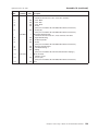
Contents
Preface . . . . . . . . . .
Who Should Read This Manual . .
How This Manual Is Organized . .
Related Publications and Diskettes
Tell Us What You Think . . . . .
Safety Information. . . . . . .
.
.
.
.
.
.
.
.
.
.
.
.
.
.
.
.
.
.
.
.
.
.
.
.
.
.
.
.
.
.
.
.
.
.
.
.
.
.
.
.
.
.
Summary of Changes . . . . . . . . . . .
Web-only update for GY27-0355-03 (October 2001) .
Web-only update for GY27-0355-03 (June 2001) . .
GY27-0355-03 . . . . . . . . . . . . . . .
GY27-0355-02 . . . . . . . . . . . . . . .
GY27-0355-01 . . . . . . . . . . . . . . .
.
.
.
.
.
.
.
.
.
.
.
.
.
.
.
.
.
.
.
.
.
.
.
.
.
.
.
.
.
.
.
.
.
.
.
.
.
.
.
.
.
.
.
.
.
.
.
.
.
.
.
.
.
.
.
.
.
.
.
.
.
.
.
.
.
.
.
.
.
.
.
.
.
.
.
.
.
.
.
.
.
.
.
.
.
.
.
.
.
.
.
.
.
.
.
.
.
.
.
.
.
.
.
.
.
.
.
.
.
.
.
.
.
.
.
.
.
.
.
.
vii
vii
vii
viii
viii
viii
xvii
xvii
xvii
xvii
xvii
xvii
Figures . . . . . . . . . . . . . . . . . . . . . . . . . . . xix
Part 1. General Information . . . . . . . . . . . . . . . . . . . . . . . . . . 1
|
|
|
|
|
|
|
|
Chapter 1. Overview . . . . . . . . . . . . . . .
Indicators, Controls, and Stations – Thermal/Impact Printers
Indicator, Control, and Station – Single-Station Printers . .
Communication Mode Selections. . . . . . . . . . .
RS-232 Baud Rate Selection . . . . . . . . . . .
RS-232 XON/XOFF Mode Selection . . . . . . . .
RS-232/RS-485 Selection . . . . . . . . . . . .
Emulation Mode Selection . . . . . . . . . . . .
USB Selection . . . . . . . . . . . . . . . . .
Power Supply Connections . . . . . . . . . . . . .
Printer Mechanism Overviews . . . . . . . . . . .
.
.
.
.
.
.
.
.
.
.
.
.
.
.
.
.
.
.
.
.
.
.
.
.
.
.
.
.
.
.
.
.
.
.
.
.
.
.
.
.
.
.
.
.
.
.
.
.
.
.
.
.
.
.
.
.
.
.
.
.
. 3
. 3
. 4
. 4
. 4
. 6
. 7
. 7
. 7
. 9
. . . . . . . . 10
Chapter 2. SureMark Installation, Service, and Utility Software . . . .
Software Adjustments (Models TI1, TI2, TI3, TI4, TG3 and TG4) . . . . .
Using the 4690 Operating System . . . . . . . . . . . . . . .
Using IBM Point-of-Sale Device Diagnostics . . . . . . . . . . .
Using the Reference/Service Diskettes (RS-485 or RS-232 Printers) . .
4610 Fonts and Logos Utility Diskette . . . . . . . . . . . . . .
Proportional Font Conversion Utility . . . . . . . . . . . . . . .
Firmware Update . . . . . . . . . . . . . . . . . . . . . .
Using Firmware Update Diskette . . . . . . . . . . . . . . .
Using POSS For Windows to Update SureMark Printer Firmware (RS-485
and USB Only) . . . . . . . . . . . . . . . . . . . . .
IBM Point-of-Sale Device Diagnostics . . . . . . . . . . . . .
Using 4690 OS 4610 Utility to Update SureMark Firmware . . . . . .
Updating SureMark Firmware Using Temporary RS-232 Attachment . .
Limitation on Updating Firmware . . . . . . . . . . . . . . .
Emulating the IBM Model 3 or Model 4 Printers . . . . . . . . . . .
Enabling Emulation Using Utility Diskettes . . . . . . . . . . . .
Enabling Emulation Using 4690 On-Line Terminal Diagnostics . . . .
Limitations for Emulation . . . . . . . . . . . . . . . . . .
Printing Saved Data . . . . . . . . . . . . . . . . . . . .
Emulating an Epson Single-Station Printer (Single-Station Only) . . . . .
Enabling Epson Emulation. . . . . . . . . . . . . . . . . .
Limitations for Epson Emulation. . . . . . . . . . . . . . . .
© Copyright IBM Corp. 1998, 2001
.
.
.
.
.
.
.
.
.
.
.
.
.
.
.
.
.
.
.
.
.
.
.
.
.
.
.
.
11
11
11
12
12
15
15
15
16
.
.
.
.
.
.
.
.
.
.
.
.
.
.
.
.
.
.
.
.
.
.
.
.
.
.
16
17
17
18
18
18
19
19
20
20
21
21
21
iii
updated October 30, 2001
MICR Data Parser Sample Code (Models TI2, TI4 and TG4 Only) . . . . . . 22
Resources on the Internet . . . . . . . . . . . . . . . . . . . . . 22
Part 2. Models TI1, TI2, TI3, TI4, TG3 and TG4 . . . . . . . . . . . . . . . . . 23
Chapter 3. Problem Determination . . . . . . . . . . . . . . . . . 25
Offline Tests . . . . . . . . . . . . . . . . . . . . . . . . . . 25
Customer Receipt Test . . . . . . . . . . . . . . . . . . . . . 25
Document Insert Test . . . . . . . . . . . . . . . . . . . . . 26
MICR Reader and Check Flipper Test (Models TI2, TI4, and TG4 Only) . . . 28
Symptoms . . . . . . . . . . . . . . . . . . . . . . . . . . 30
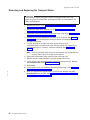
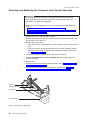
Customer Receipt Paper Movement and Cutter Problems . . . . . . . . . 35
FRU Removal and Replacement . . . . . . . . . . . . . . . . . . 37
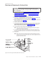
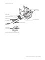
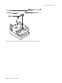
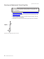
Removing and Replacing the Top, Paper, and Ribbon Covers. . . . . . . 37
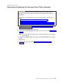
Removing and Replacing the Top Cover Operator Buttons . . . . . . . . 41
Removing and Replacing the Document Insert Lower Cover and Flipper
Cartridge . . . . . . . . . . . . . . . . . . . . . . . . . 42
Removing and Replacing the Printhead . . . . . . . . . . . . . . . 43
Removing and Replacing the Home Sensor . . . . . . . . . . . . . 44
Removing and Replacing the Ribbon Drive Assembly. . . . . . . . . . 45
Removing and Replacing the Tensioner . . . . . . . . . . . . . . . 47
Removing and Replacing the Printhead Carriage Assembly . . . . . . . 48
Removing and Replacing the Transport Motor . . . . . . . . . . . . 52
Removing and Replacing the Printhead Cable . . . . . . . . . . . . 55
Removing and Replacing the Document Insert Sensor Assembly . . . . . 56
Removing and Replacing the Document Insert Platen Assembly . . . . . . 59
Removing and Replacing the MICR Read Head . . . . . . . . . . . . 61
Removing and Replacing the Lower Forms Entry Frame or Flipper Assembly 64
Removing and Replacing the Document Insert Backup Roller and Insert
Lever Assembly . . . . . . . . . . . . . . . . . . . . . . . 68
Removing and Replacing the DI Feed Roller . . . . . . . . . . . . . 71
Removing and Replacing the Switch Card and Printhead Spacer . . . . . 75
Removing and Replacing the Main Logic Card and Cable-Attached Interface
Card (Models TI1 and TI2) . . . . . . . . . . . . . . . . . . . 76
Removing and Replacing the Main Logic Card and Connector-Attached
Interface Card (Models TI3, TI4, TG3, and TG4) . . . . . . . . . . . 79
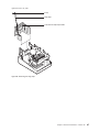
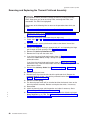
Removing and Replacing the Thermal Cables and Paper Switch . . . . . 81
Removing and Replacing the Thermal Latch . . . . . . . . . . . . . 84
Removing and Replacing the Thermal Drag Strip . . . . . . . . . . . 86
Removing and Replacing the Thermal Printhead Assembly. . . . . . . . 88
Removing and Replacing the Thermal Platen Assembly . . . . . . . . . 91
Removing and Replacing the Customer Receipt Motor . . . . . . . . . 92
Removing and Replacing the Rotating Cutter Blade and Thermal Guide . . . 93
Removing and Replacing the Cutter Gears and Cutter Clutch . . . . . . . 94
Removing and Replacing the Customer Receipt Paper Guide. . . . . . . 96
Removing and Replacing the Customer Receipt Paper Bucket . . . . . . 97
Removing and Replacing the Document Insert Motor and Gears . . . . . 100
Chapter 4. Hardware Adjustment Procedures
Electrostatic Discharge (ESD) . . . . . . .
Mechanical Adjustments . . . . . . . . .
DI Forms Compensation Adjustment . . .
Printhead Platen Gap Adjustment . . . .
DI Open Lever Adjustment . . . . . . .
Cutter Blade Run-In . . . . . . . . . .
Thermal Printhead Adjustment . . . . . .
iv
SureMark Hardware Service
.
.
.
.
.
.
.
.
.
.
.
.
.
.
.
.
.
.
.
.
.
.
.
.
.
.
.
.
.
.
.
.
.
.
.
.
.
.
.
.
.
.
.
.
.
.
.
.
.
.
.
.
.
.
.
.
.
.
.
.
.
.
.
.
.
.
.
.
.
.
.
.
.
.
.
.
.
.
.
.
.
.
.
.
.
.
.
.
.
.
.
.
.
.
.
.
105
105
106
106
108
110
111
114
updated October 30, 2001
Thermal Paper Switch Adjustment . . . . . . . . . . . . . . . . 116
Document Sensor Threshold Reset . . . . . . . . . . . . . . . . 117
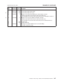
Chapter 5. Parts Listing. . . . . . . . . . . . . .
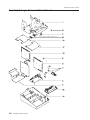
Assembly 1: Covers . . . . . . . . . . . . . . .
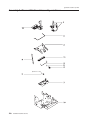
Assembly 2: Operator Switch and Button Assembly . . . .
Assembly 3: Logic Cards and Shock Mounts . . . . . .
Assembly 4: Document Insert Station . . . . . . . . .
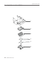
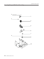
Assembly 5: Thermal Printhead Assembly and Cover . . .
Assembly 6: Printhead Transport and Ribbon Drive Assembly
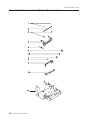
Assembly 7: Impact Printhead Assembly . . . . . . . .
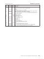
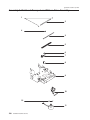
Assembly 8: Document Insert Station Platen and Lever . .
Assembly 9: Document Insert Drive Shaft Assembly . . . .
Assembly 10: Document Insert Station Gears and Motor . .
Assembly 11: Customer Receipt Drive, Cutter, and Platen .
Assembly 12: Hardware Kits . . . . . . . . . . . .
Assembly 13: Cable Assemblies, Filler Panel, Power Supply.
.
.
.
.
.
.
.
.
.
.
.
.
.
.
.
.
.
.
.
.
.
.
.
.
.
.
.
.
.
.
.
.
.
.
.
.
.
.
.
.
.
.
.
.
.
.
.
.
.
.
.
.
.
.
.
.
.
.
.
.
.
.
.
.
.
.
.
.
.
.
.
.
.
.
.
.
.
.
.
.
.
.
.
.
.
.
.
.
.
.
.
.
.
.
.
.
.
.
119
120
122
124
126
128
130
132
134
136
138
140
142
144
Chapter 6. Operation . . . . . . . .
Operating Controls and Indicators . . .
Check Verification and Printing . . . .
Ribbon Loading . . . . . . . . . .
Paper Loading . . . . . . . . . .
Clearing Jams in the Check Flipper Area .
MICR Reader Read Head Cleaning . . .
Thermal Printhead Cleaning . . . . .
.
.
.
.
.
.
.
.
.
.
.
.
.
.
.
.
.
.
.
.
.
.
.
.
.
.
.
.
.
.
.
.
.
.
.
.
.
.
.
.
.
.
.
.
.
.
.
.
.
.
.
.
.
.
.
.
147
147
147
151
153
155
157
158
.
.
.
.
.
.
.
.
.
.
.
.
.
.
.
.
.
.
.
.
.
.
.
.
.
.
.
.
.
.
.
.
.
.
.
.
.
.
.
.
.
.
.
.
.
.
.
.
.
.
.
.
.
.
.
.
| Part 3. Models TF6 and TM6 . . . . . . . . . . . . . . . . . . . . . . . . . 159
|
|
|
|
|
|
|
|
|
|
|
|
Chapter 7. Problem Determination . . . . . . . . . . . .
Offline Diagnostics . . . . . . . . . . . . . . . . . . .
Customer Receipt Test . . . . . . . . . . . . . . . .
Listing the MCT Settings . . . . . . . . . . . . . . . .
RS-232 Hex Dump . . . . . . . . . . . . . . . . . .
Symptoms . . . . . . . . . . . . . . . . . . . . . .
Customer Receipt Paper Movement and Cutter Problems. . . . .
FRU Removal and Replacement . . . . . . . . . . . . . .
Removing and Replacing the Top Cover and Inner Cover Assembly
Removing and Replacing the Bottom Cover . . . . . . . . .
Removing and Replacing the Interface and Main Logic Cards . .
Removing and Replacing the Thermal Print Mechanism . . . .
|
|
|
Chapter 8. Hardware Adjustment Procedures . . . . . . . . . . . . 175
Electrostatic Discharge (ESD) . . . . . . . . . . . . . . . . . . . 175
Thermal Paper Switch Adjustment . . . . . . . . . . . . . . . . . 176
|
|
|
|
|
|
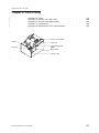
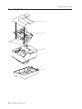
Chapter 9. Parts Listing . . . . . . . . . .
Assembly 14: Covers . . . . . . . . . . . .
Assembly 15: Interface and Logic Cards . . . . .
Assembly 16: Thermal Printhead Assembly . . . .
Assembly 17: Hardware Kits . . . . . . . . .
Assembly 18: Miscellaneous Parts and Accessories .
|
|
|
Chapter 10. Operation . . . . . . . . . . . . . . . . . . . . . 189
Operating Controls and Indicators . . . . . . . . . . . . . . . . . 189
Paper Loading . . . . . . . . . . . . . . . . . . . . . . . . 190
.
.
.
.
.
.
.
.
.
.
.
.
.
.
.
.
.
.
.
.
.
.
.
.
.
.
.
.
.
.
.
.
.
.
.
.
.
.
.
.
.
.
.
.
.
.
.
.
.
.
.
.
.
.
.
.
.
.
.
.
.
.
.
.
.
.
.
.
.
.
.
.
.
.
.
.
.
.
.
.
.
.
.
.
.
.
.
.
.
.
.
.
.
.
.
.
.
.
.
.
.
.
.
.
.
.
.
.
Contents
161
161
161
162
163
163
165
167
167
169
170
172
177
178
180
182
184
186
v
updated October 30, 2001
Thermal Printhead Cleaning
|
. . . . . . . . . . . . . . . . . . . 191
Part 4. Appendixes . . . . . . . . . . . . . . . . . . . . . . . . . . . . . 193
Appendix A. Maintenance Inspection . . . . . . . . . . . . . . . 195
Maintenance Checklist . . . . . . . . . . . . . . . . . . . . . 195
Appendix B. Preventive Maintenance Information . . . . . . . . . . 197
Models TI1, TI2, TI3, TI4, TG3, and TG4 . . . . . . . . . . . . . . . 197
Models TF6 and TM6 . . . . . . . . . . . . . . . . . . . . . . 197
|
Appendix C. Tools and Supplies . . .
Special Tools . . . . . . . . . . .
Expendable Supplies . . . . . . . .
RS-232 Connector Pin Assignments . .
USB Connector Pin Assignments . . . .
Cash Drawer Connector Pin Assignments
.
.
.
.
.
.
.
.
.
.
.
.
.
.
.
.
.
.
.
.
.
.
.
.
.
.
.
.
.
.
.
.
.
.
.
.
.
.
.
.
.
.
.
.
.
.
.
.
.
.
.
.
.
.
.
.
.
.
.
.
.
.
.
.
.
.
.
.
.
.
.
.
.
.
.
.
.
.
.
.
.
.
.
.
199
199
199
199
199
200
Appendix D. Translated Safety Notices. .
Nederlands - België. . . . . . . . . .
Algemene veiligheidsvoorschriften . . .
Français - Belgique . . . . . . . . . .
Consignes de sécurité générales . . . .
Português do Brasil. . . . . . . . . .
Considerações Gerais sobre Seguranç’a .
Dansk. . . . . . . . . . . . . . .
Generelle sikkerhedsforskrifter. . . . .
Suomi. . . . . . . . . . . . . . .
Yleiset turvaohjeet . . . . . . . . .
Français . . . . . . . . . . . . . .
Généralités . . . . . . . . . . . .
Deutsch . . . . . . . . . . . . . .
Allgemeine Sicherheitsüberlegungen . .
Italiano . . . . . . . . . . . . . .
Sicurezza - Considerazioni generali . . .
Norsk . . . . . . . . . . . . . . .
Generelle sikkerhetsforskrifter . . . . .
Português . . . . . . . . . . . . .
Informaçõles de Segurança Gerais . . .
Español . . . . . . . . . . . . . .
Consideraciones Generales de Seguridad
Svenska . . . . . . . . . . . . . .
Allmänna säkerhetsföreskrifter . . . . .
.
.
.
.
.
.
.
.
.
.
.
.
.
.
.
.
.
.
.
.
.
.
.
.
.
.
.
.
.
.
.
.
.
.
.
.
.
.
.
.
.
.
.
.
.
.
.
.
.
.
.
.
.
.
.
.
.
.
.
.
.
.
.
.
.
.
.
.
.
.
.
.
.
.
.
.
.
.
.
.
.
.
.
.
.
.
.
.
.
.
.
.
.
.
.
.
.
.
.
.
.
.
.
.
.
.
.
.
.
.
.
.
.
.
.
.
.
.
.
.
.
.
.
.
.
.
.
.
.
.
.
.
.
.
.
.
.
.
.
.
.
.
.
.
.
.
.
.
.
.
.
.
.
.
.
.
.
.
.
.
.
.
.
.
.
.
.
.
.
.
.
.
.
.
.
.
.
.
.
.
.
.
.
.
.
.
.
.
.
.
.
.
.
.
.
.
.
.
.
.
.
.
.
.
.
.
.
.
.
.
.
.
.
.
.
.
.
.
.
.
.
.
.
.
.
.
.
.
.
.
.
.
.
.
.
.
.
.
.
.
.
.
.
.
.
.
.
.
.
.
.
.
.
.
.
.
.
.
.
.
.
.
.
.
.
.
.
.
.
.
.
.
.
.
.
.
.
.
.
.
.
.
.
.
.
.
.
.
.
.
.
.
.
.
.
.
.
.
.
.
.
.
.
.
.
.
.
.
.
.
.
.
.
.
.
.
.
.
.
.
.
.
.
.
.
201
201
201
201
201
202
202
202
202
203
203
204
204
204
204
205
205
205
205
205
205
206
206
207
207
Appendix E. Notices . . . . . . . . . . . . . . . . . . . . . . 209
Electrostatic Discharge (ESD) . . . . . . . . . . . . . . . . . . . 209
Trademarks. . . . . . . . . . . . . . . . . . . . . . . . . . 209
Part Number Index
. . . . . . . . . . . . . . . . . . . . . . 211
Index . . . . . . . . . . . . . . . . . . . . . . . . . . . . 213
vi
SureMark Hardware Service
updated October 30, 2001
Preface
This manual provides problem determination and testing information and a parts
listing of field-replaceable units (FRUs) for the IBM SureMark Printers.
Who Should Read This Manual
This manual is intended for use by trained service representatives.
How This Manual Is Organized
Part 1 contains information for all SureMark printers:
v Chapter 1. Overview – an overview of the features of the SureMark printers.
v Chapter 2. SureMark Installation, Service, and Utility Software – information
about using the utilities diskettes.
Part 2 contains the following information that is specific to the thermal/impact
SureMark printers – models TI1, TI2, TI3, and TI4:
v Chapter 3. Problem Determination – information about testing, messages, and
symptoms for determining any failing components of the SureMark printer. This
chapter also includes procedures for removing and replacing components in the
SureMark printer.
v Chapter 4. Hardware Adjustment Procedures – printer adjustment procedures.
v Chapter 5. Parts Listing – part numbers of the field replaceable units (FRUs) for
the SureMark printer.
v Chapter 6. Operation – information on operating the SureMark printer.
Part 3 contains the following information that is specific to the single-station
SureMark printers – models TF6 and TM6:
v Chapter 7. Problem Determination – information on testing, messages, and
symptoms for determining any failing components of the SureMark printer. This
chapter also includes procedures for removing and replacing components in the
SureMark printer.
v Chapter 8. Hardware Adjustment Procedures – printer adjustment procedures.
v Chapter 9. Parts Listing – part numbers of the field replaceable units (FRUs) for
the SureMark printer.
v Chapter 10. Operation – information on operating the SureMark printer.
The appendixes contain the following information:
v Appendix A. Maintenance Inspection –checklist to be used during an IBM
maintenance inspection.
v Appendix B. Preventive Maintenance Information – preventive maintenance
procedures for the SureMark printer.
v Appendix C. Tools and Supplies – information about special tools for the
SureMark printer and the pin assignments you need to know if you use non-IBM
cables.
v Appendix D. Translated Safety Notices – translations of the safety notices in this
manual.
v Appendix E. Notices – electronic emission notices and other general information.
© Copyright IBM Corp. 1998, 2001
vii
updated October 30, 2001
Related Publications and Diskettes
v
v
v
v
IBM
IBM
IBM
IBM
v
v
v
v
v
IBM SurePOS 700 Series: Hardware Service Guide, GA27-0363
IBM SurePOS 700 Series: Options and I/0 Devices Service Guide, SY27-0392
IBM SurePOS 700 Series: System Reference, SA27-4224
IBM SurePOS 500 Series: System Reference, SA27-4255
POSS Programming Reference and User’s Guide, SC30-3560
SureMark Printers: User’s Guide, GA27-4151
SureMark Printers: firmware update diskettes
SureMark Printers: Fonts and Logos Utility Diskette
Safety Information – Read This First, GA27-4004
The diskettes are only available by download from the Internet. See “Resources on
the Internet” on page 22 for more information.
For information about ordering IBM publications not shipped with the SureMark,
contact your IBM representative or your place of purchase.
SureMark publications are available on the Internet as PDF files. See “Resources
on the Internet” on page 22 for more information.
Tell Us What You Think
Your feedback is important in helping to provide the most accurate and high-quality
information. Please take a few moments to tell us what you think about this book.
The only way for us to know if you are satisfied with our books, or how we might
improve their quality, is through feedback from customers like you. If you have any
comments about this book, there is a comment form at the back of this book. You
can also get a copy of the form from the PDF version of the book on the Web.
To access a PDF version of this book, visit the Retail Store Solutions Web site at:
http://www.ibm.com/solutions/retail/store
From there, select Support at the left, then select Publications.
After you have filled out the form, return it by mail, by fax, or by giving it to an IBM
representative. If applicable, include a reference to the specific location of the text
on which you are commenting. For instance, include the page or table number.
Between major revisions of this manual we may make minor technical updates. The
latest softcopy version of this manual is available under Publications on the IBM
Retail Store Solutions Web site.
Safety Information
viii
SureMark Hardware Service
updated October 30, 2001
Danger:
Before you begin to install this product, read the safety information in IBM
Safety Information — Read This First, GA27–4004. This booklet describes
safe procedures for cabling and plugging in electrical equipment.
Gevaar:
Voordat u begint met de installatie van dit produkt, moet u eerst de
veiligheidsinstructies lezen in de brochure Veiligheidsinstructies—Lees dit
eerst, GA27–4004. Hierin wordt beschreven hoe u electrische apparatuur op
een veilige manier moet bekabelen en aansluiten.
Perigo:
Antes de começar a instalar este produto, leia as informações de segurança
contidas em Informações Sobre Seguranaça—Leia Isto Primeiro, GA27–4004.
Esse folheto descreve procedimentos de segurança para a instalação de
cabos e conexões em equipamentos elétricos.
Fare!
Før du installerer dette produkt, skal du læse sikkerhedsforskrifterne i
Sikkerhedsforskrifter—Lœs dette først GA27–4004. Vejledningen beskriver den
fremgangsmåde, du skal bruge ved tilslutning af kabler og udstyr.
Gevaar
Voordat u begint met het installeren van dit produkt, dient u eerst de
veiligheidsrichtlijnen te lezen die zijn vermeld in de publikatie IBM Safety
Information — Read This First, GA27–4004. In dit boekje vindt u veilige
procedures voor het aansluiten van elektrische appratuur.
Preface
ix
updated October 30, 2001
VAARA
Ennen kuin aloitat tämän tuotteen asennuksen, lue julkaisussa
Turvaohjeet—Luetämä ensin, GA27–4004, olevat turvaohjeet. Tässä
kirjasessa on ohjeet siitä, miten sähkölaitteet kaapeloidaan ja kytketään
turvallisesti.
Danger
Avant d’installer le présent produit, consultez le livret Informations pour la
sécurité–Lisez-moi d’abord, GA27–4004, qui décrit les procédures à respecter
pour effectuer les opérations de câblage et brancher les équipements
électriques en toute sécurité.
Vorsicht
Bevor mit der Installation des Produktes begonnen wird, die
Sicherheitshinweise in Sicherheitsinformationen—Bitte zuerst lesen, IBM Form
GA27–4004. Diese Veröffentlichung beschreibt die Sicherheitsvorkehrungen
für das Verkabeln und Anschlieβen elektrischer Geräte.
Vigyázat
Mielôtt megkezdi a berendezés üzembe helyezését, olvassa el a IBM Safety
Information — Read This First, GA27–4004 könyvecskében leírt biztonsági
információkat. Ez a könyv leírja, milyen biztonsági intézkedéseket kell
megtenni az elektromos berendezés huzalozásakor illetve csatlakoztatásakor.
x
SureMark Hardware Service
updated October 30, 2001
Pericolo
prima di iniziare l’installazione di questo prodotto, leggere le informazioni
relative alla sicurezza riportate nell’opuscolo Informazioni di sicurezza—Prime
informazioni da leggere in cui sono descritte le procedure per il cablaggio ed il
collegamento di apparecchiature elettriche.
Fare
Før du begynner å installere dette produktet, må du lese
sikkerhetsinformasjonen i Sikkerhetsinformasjon—Les dette først, GA27–4004
som beskriver sikkerhetsrutinene for kabling og tilkobling av elektrisk utstyr.
Perigo
Antes de iniciar a instalação deste produto, leia as informações de segurança
Informações de Segurança—Leia Primeiro, GA27–4004. Este documento
descreve como efectuar, de um modo seguro, as ligações eléctricas dos
equipamentos.
Peligro
Antes de empezar a instalar este producto, lea la información de seguridad en
Información de Seguridad—Lea Esto Primero, GA27–4004. Este documento
describe los procedimientos de sequridad para cablear y enchufar equipos
eléctricos.
Preface
xi
updated October 30, 2001
Varning—livsfara
Innan du börjar installera den här produkten bör du läsa
säkerhetsinformationen i dikumentet Säkerhetsföreskrifter—Läs detta först,
GA27–4004. Där beskrivs hur du på ett säkert sätt ansluter elektrisk
utrustning.
xii
SureMark Hardware Service
updated October 30, 2001
GA27-4004
GA27-4004
Preface
xiii
updated October 30, 2001
xiv
SureMark Hardware Service
updated October 30, 2001
Preface
xv
updated October 30, 2001
xvi
SureMark Hardware Service
updated October 30, 2001
Summary of Changes
This section summarizes the changes included in the latest editions of this manual.
Web-only update for GY27-0355-03 (October 2001)
This update corrects the parts catalog information for the covers on models TM6
and TF6. Refer to “Assembly 14: Covers” on page 178 for revision bars that indicate
the changed information.
Web-only update for GY27-0355-03 (June 2001)
This update adds information about the new TG3 and TG4 models. Refer to
“Chapter 5. Parts Listing” on page 119 for revision bars that show which parts that
have been added.
GY27-0355-03
This edition includes information about the new single-station SureMark printers,
which are models TF6 and TM6, and also includes updates for models TI3 and TI4.
Changed or new information is indicated by a revision bar (|) in the left margin.
(There are no revision bars in the margin of figures. Refer to “Figures” on page xix
for revision bars that show which figures have been changed.)
There are both similarities and important differences between the thermal/impact
SureMark printers (models TI1, TI2, TI3 and TI4) and the single-station SureMark
printers (models TF6 and TM6). For that reason, this document has been
reorganized and divided into parts.
v “Part 1. General Information” on page 1 contains information that is similar for all
SureMark models. Information about the new single-station printers has been
added throughout this part.
v “Part 2. Models TI1, TI2, TI3, TI4, TG3 and TG4” on page 23 contains information
about the thermal/impact printers. This information has a few changes from the
previous edition.
v “Part 3. Models TF6 and TM6” on page 159 contains information about the
single-station printers. All information in this part is new in this edition.
GY27-0355-02
This edition includes information about USB support for the SureMark printer.
GY27-0355-01
This edition includes information about two new models of the SureMark printer –
Model TI3 and Model TI4. Because Model TI3 is a new version of Model TI1, and
Model TI4 is a new version of Model TI2, in some cases only the new model
number was added to the existing text.
Information sections that were added include:
v “Removing and Replacing the Home Sensor” on page 44
v “Removing and Replacing the Main Logic Card and Connector-Attached Interface
Card (Models TI3, TI4, TG3, and TG4)” on page 79
© Copyright IBM Corp. 1998, 2001
xvii
updated October 30, 2001
v “Removing and Replacing the Rotating Cutter Blade and Thermal Guide” on
page 93
v “Firmware Update” on page 15
v “Emulating the IBM Model 3 or Model 4 Printers” on page 18
v “MICR Data Parser Sample Code (Models TI2, TI4 and TG4 Only)” on page 22
v “RS-232 Connector Pin Assignments” on page 199
v “Cash Drawer Connector Pin Assignments” on page 200
Because documentation, drivers, and diskettes are now available on the Web,
“Resources on the Internet” on page 22 was added to describe how to locate the
applicable Web site.
Information that was changed includes:
v “Symptoms” on page 30, the table that describes the actions to take for various
printer problems.
v “Customer Receipt Paper Movement and Cutter Problems” on page 35.
v “Removing and Replacing the Transport Motor” on page 52 and “Removing and
Replacing the Printhead Cable” on page 55, which were previously one combined
procedure.
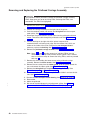
v Many of the remove/replace procedures. The procedures that have been greatly
revised include:
– “Removing and Replacing the Top, Paper, and Ribbon Covers” on page 37
– “Removing and Replacing the Printhead” on page 43
– “Removing and Replacing the Ribbon Drive Assembly” on page 45
– “Removing and Replacing the Document Insert Platen Assembly” on page 59
– “Removing and Replacing the MICR Read Head” on page 61
– “Removing and Replacing the Thermal Platen Assembly” on page 91
– “Removing and Replacing the Customer Receipt Motor” on page 92
– “Removing and Replacing the Cutter Gears and Cutter Clutch” on page 94
v “Thermal Paper Switch Adjustment” on page 116
v “Chapter 5. Parts Listing” on page 119
Many of the figures have been revised to make it easier to locate the parts of the
printer that are referenced in the related text.
Some information has been moved:
v “Document Sensor Threshold Reset” on page 117 was in Chapter 1 in the
previous edition.
v “Using the 4690 Operating System” on page 11 and “Using the
Reference/Service Diskettes (RS-485 or RS-232 Printers)” on page 12 were in
Chapter 2 in the previous edition.
xviii
SureMark Hardware Service
updated October 30, 2001
Figures
|
|
|
2
|
2
|
|
1. Indicators, Controls, and Printing Stations – Thermal/Impact SureMark Printers . .
2. Indicator, Control, and Printing Station – Single-Station SureMark Printers . . . .
3. Cable Connectors and RS-232 Mode Switch for Thermal/Impact SureMark Printers .
4. Cable Connectors for Single-Station SureMark Printers . . . . . . . . . . .
5. RS-232 Mode Switch for Single-Station SureMark Printers . . . . . . . . . .
6. RS-232 and RS-485 Cable Routing for Single-Station SureMark Printers. . . . .
7. USB Ports for Thermal/Impact SureMark Printers . . . . . . . . . . . . .
8. USB Ports for Single-Station SureMark Printers . . . . . . . . . . . . . .
9. USB Cable Routing for Single-Station SureMark Printers . . . . . . . . . .
10. Printer Mechanism Overview – Thermal/Impact Printers . . . . . . . . . .
11. Printer Mechanism Overview – Single-Station Printers . . . . . . . . . . .
12. Adjustment and Alignment Printouts . . . . . . . . . . . . . . . . . .
13. Switch for Epson Emulation . . . . . . . . . . . . . . . . . . . . .
14. Offline Printer Test Pattern (Thermal/Impact SureMark Printers). . . . . . . .
15. MICR Reader Test Results – Good Noise Level . . . . . . . . . . . . .
16. MICR Reader Test Results – Noise Level Needs Adjusting . . . . . . . . .
17. Customer Receipt Gears . . . . . . . . . . . . . . . . . . . . . .
18. Removing the Paper and Ribbon Covers . . . . . . . . . . . . . . . .
19. Removing the Top Cover . . . . . . . . . . . . . . . . . . . . . .
20. Removing the Operator Buttons in the Top Cover . . . . . . . . . . . . .
21. Removing the Document Insert Feed Cover and the Flipper Cartridge . . . . .
22. Replacing the Printhead . . . . . . . . . . . . . . . . . . . . . .
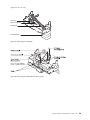
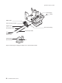
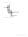
23. Removing the Ribbon Drive Assembly . . . . . . . . . . . . . . . . .
24. Removing the Tensioner . . . . . . . . . . . . . . . . . . . . . .
25. Removing the Timing Belt . . . . . . . . . . . . . . . . . . . . .
26. Removing the Printhead/Home Sensor Cable . . . . . . . . . . . . . .
27. Removing the Carriage Assembly, Front or Rear Transport Shafts . . . . . . .
28. Removing the Front Transport Carrier Bearing . . . . . . . . . . . . . .
29. Removing the Timing Belt . . . . . . . . . . . . . . . . . . . . .
30. Turning the Bushing and Removing the Transport Shaft . . . . . . . . . .
31. Removing the Transport Motor . . . . . . . . . . . . . . . . . . . .
32. Disconnecting the Printhead Cable and Home Sensor . . . . . . . . . . .
33. Removing the Timing Belt . . . . . . . . . . . . . . . . . . . . .
34. Removing the Front Transport Shaft . . . . . . . . . . . . . . . . . .
35. Disconnecting the Sensor Spring and Removing the DI Insert Assembly . . . .
36. Removing the Document Insert Platen Assembly . . . . . . . . . . . . .
37. Disconnecting the Main Logic Card Cables . . . . . . . . . . . . . . .
38. Removing the Front Shock Mount . . . . . . . . . . . . . . . . . .
39. Removing the MICR . . . . . . . . . . . . . . . . . . . . . . .
40. Disconnecting the Main Logic Card Cables (Models TI1 and TI2) . . . . . . .
41. Disconnecting the Main Logic Card Cables (Models TI3, TI4, TG3, and TG4) . .
42. Disconnecting the MICR Cable. . . . . . . . . . . . . . . . . . . .
43. Removing the Lower Forms Entry Frame . . . . . . . . . . . . . . . .
44. Removing the Flipper Assembly . . . . . . . . . . . . . . . . . . .
45. Removing the Bail . . . . . . . . . . . . . . . . . . . . . . . .
46. Removing the DI Backup Roller . . . . . . . . . . . . . . . . . . .
47. Removing the DI Lever Assembly. . . . . . . . . . . . . . . . . . .
48. Disconnecting the Main Logic Card Cables (Models TI1 and TI2) . . . . . . .
49. Disconnecting the Main Logic Card Cables (Models TI3 TI4, TG3, and TG4) . . .
50. Removing the Front Shock Mount and Disconnecting the MICR Cable . . . . .
51. Gear Removal . . . . . . . . . . . . . . . . . . . . . . . . . .
52. Removing the Document Insert Feed Roller . . . . . . . . . . . . . . .
53. Removing the Switch Card and Printhead Spacer . . . . . . . . . . . . .
© Copyright IBM Corp. 1998, 2001
.
.
.
.
.
.
.
.
.
.
.
.
.
.
.
.
.
.
.
.
.
.
.
.
.
.
.
.
.
.
.
.
.
.
.
.
.
.
.
.
.
.
.
.
.
.
.
.
.
.
.
.
.
.
.
.
.
.
.
.
.
.
.
.
.
.
.
.
.
.
.
.
.
.
.
.
.
.
.
.
.
.
.
.
.
.
.
.
.
.
.
.
.
.
.
.
.
.
.
.
.
.
.
.
.
.
.
.
.
.
.
.
.
.
.
.
.
.
.
.
.
.
.
.
.
.
.
.
.
.
.
.
.
.
.
.
.
.
.
.
.
.
.
.
.
.
.
.
.
.
.
.
.
.
.
.
.
.
.
.
.
.
.
.
.
.
.
.
.
.
.
.
.
.
.
.
.
.
.
.
.
.
.
.
.
.
.
.
.
.
.
.
.
.
.
.
.
.
.
.
.
.
.
.
.
.
.
.
.
.
.
.
.
.
.
.
.
.
.
.
.
.
.
.
.
.
.
.
.
.
.
.
.
.
.
.
.
.
.
.
.
.
.
.
.
.
.
.
.
.
.
.
.
.
.
.
.
.
.
.
.
.
.
.
.
. 4
. 4
. 5
. 5
. 6
. 6
. 8
. 8
. 9
. 10
. 10
. 14
. 21
. 27
. 28
. 29
. 36
. 39
. 40
. 41
. 42
. 43
. 46
. 47
. 49
. 49
. 50
. 51
. 53
. 53
. 54
. 55
. 56
. 57
. 58
. 60
. 62
. 62
. 63
. 65
. 65
. 66
. 66
. 67
. 67
. 69
. 70
. 72
. 72
. 73
. 73
. 74
. 75
xix
updated October 30, 2001
|
|
|
|
54. Disconnecting the Main Logic Card Cables (Models TI1 and TI2) . . . . . . . . . . . . . 77
55. Disconnecting the Main Logic Card Cables (Models TI3, TI4, TG3, and TG4) . . . . . . . . 77
56. Removing the Front Shock Mount and Disconnecting the MICR Cable . . . . . . . . . . . 78
57. Removing the Logic Card and the Interface Card . . . . . . . . . . . . . . . . . . . 78
58. Removing the Interface Card Assembly . . . . . . . . . . . . . . . . . . . . . . 80
59. Removing the Thermal Cover . . . . . . . . . . . . . . . . . . . . . . . . . . 81
60. Removing the Spiral Wraps . . . . . . . . . . . . . . . . . . . . . . . . . . . 82
61. Disconnecting the Thermal Cables from the Main Logic Card (Models TI1 and TI2) . . . . . . 82
62. Disconnecting the Thermal Cable from the Main Logic Card (Models TI3, TI4, TG3, and TG4)
83
63. Thermal Latch Assembly . . . . . . . . . . . . . . . . . . . . . . . . . . . . 84
64. Removing the Thermal Latch Spring. . . . . . . . . . . . . . . . . . . . . . . . 85
65. View of Drag Strip from Back of Printer . . . . . . . . . . . . . . . . . . . . . . 86
66. Removing the Drag Strip . . . . . . . . . . . . . . . . . . . . . . . . . . . . 87
67. Thermal Printhead Assembly . . . . . . . . . . . . . . . . . . . . . . . . . . 89
68. Removing the Spiral Wraps . . . . . . . . . . . . . . . . . . . . . . . . . . . 89
69. Removing the Cutter Stud, Stationary Blade, and Printhead Shaft (Models TI1 and TI2). . . . . 90
70. Removing the Cutter Stud, Stationary Blade, and Printhead Shaft (Models TI3, TI4, TG3, and
TG4) . . . . . . . . . . . . . . . . . . . . . . . . . . . . . . . . . . . 90
71. Removing the Thermal Platen Assembly . . . . . . . . . . . . . . . . . . . . . . 91
72. Removing the Customer Receipt Motor . . . . . . . . . . . . . . . . . . . . . . 92
73. Removing the Rotating Blade and Thermal Guide (Models TI1 and TI2) . . . . . . . . . . 93
74. Removing the Rotating Blade and Thermal Guide (Models TI3, TI4, TG3, and TG4) . . . . . . 94
75. Removing the Cutter Gears . . . . . . . . . . . . . . . . . . . . . . . . . . . 95
76. Removing the Customer Receipt Paper Guide . . . . . . . . . . . . . . . . . . . . 96
77. Disconnecting the Cables Connected to the Main Logic Card (Models TI1 and TI2) . . . . . . 97
78. Disconnecting the Cable Connected to the Main Logic Card (Models TI3, TI4, TG3, and TG4)
98
79. Removing the Front Shock Mount and Disconnecting the MICR Cable . . . . . . . . . . . 98
80. Customer Receipt Paper Bucket . . . . . . . . . . . . . . . . . . . . . . . . . 99
81. Disconnecting the Logic Card Cables (Models TI1 and TI2). . . . . . . . . . . . . . . 101
82. Disconnecting the Logic Card Cables (Models TI3, TI4, TG3, and TG4) . . . . . . . . . . 101
83. Removing the Front Shock Mount and Disconnecting the MICR Cable. . . . . . . . . . . 102
84. Removing the Motor Gear and Idler Gear . . . . . . . . . . . . . . . . . . . . . 102
85. Removing the Document Insert Feed Motor . . . . . . . . . . . . . . . . . . . . 103
86. DI Forms Adjustment . . . . . . . . . . . . . . . . . . . . . . . . . . . . . 107
87. Placement of Gap Setting Tool . . . . . . . . . . . . . . . . . . . . . . . . . 109
88. Platen Gap Adjustment . . . . . . . . . . . . . . . . . . . . . . . . . . . . 109
89. DI Open Lever Adjustment . . . . . . . . . . . . . . . . . . . . . . . . . . . 110
90. Cutter Blade Run-In (Models TI1 and TI2) . . . . . . . . . . . . . . . . . . . . . 112
91. Cutter Blade Run-In (Models TI3 TI4, TG3 and TG4) . . . . . . . . . . . . . . . . . 113
92. Thermal Printhead Adjustment . . . . . . . . . . . . . . . . . . . . . . . . . 115
93. Thermal Paper Switch Adjustment . . . . . . . . . . . . . . . . . . . . . . . . 116
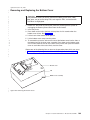
94. Positioning Checks and Documents for Reading and Printing in a Model TI2, TI4, or TG4 Printer 148
95. Printable Area of an Inserted Document (Portrait) . . . . . . . . . . . . . . . . . . 149
96. Printable Area of an Inserted Document (Landscape) . . . . . . . . . . . . . . . . . 150
97. Opening the Ribbon Cover . . . . . . . . . . . . . . . . . . . . . . . . . . . 151
98. Ribbon Cartridge Loading . . . . . . . . . . . . . . . . . . . . . . . . . . . 151
99. Ribbon Path around the Printhead . . . . . . . . . . . . . . . . . . . . . . . . 152
100. Paper Cover . . . . . . . . . . . . . . . . . . . . . . . . . . . . . . . . 153
101. Paper Loading Path . . . . . . . . . . . . . . . . . . . . . . . . . . . . . 154
102. Removing the Lower Document Insert (DI) Cover . . . . . . . . . . . . . . . . . . 155
103. Removing the Check Flipper Cartridge . . . . . . . . . . . . . . . . . . . . . . 156
104. Printhead and Print Line Area. . . . . . . . . . . . . . . . . . . . . . . . . . 158
105. Offline Printer Test Pattern (Models TF6 and TM6) . . . . . . . . . . . . . . . . . . 162
106. Thermal Drive Gear . . . . . . . . . . . . . . . . . . . . . . . . . . . . . 165
107. Paper Out Switch and Idler Gear . . . . . . . . . . . . . . . . . . . . . . . . 166
108. Removing the Top Cover and Inner Cover Assembly . . . . . . . . . . . . . . . . . 168
xx
SureMark Hardware Service
updated October 30, 2001
|
|
|
|
|
2
2
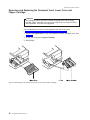
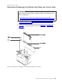
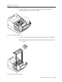
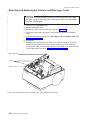
109. Removing the Bottom Cover . . . . . . . . . . . . . . . .
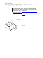
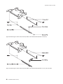
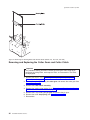
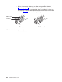
110. Removing the Interface and Main Logic Cards – Models TF6 and TM6
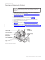
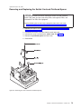
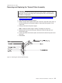
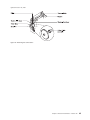
111. Separating the Interface and Main Logic Cards – Models TF6 and TM6
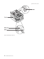
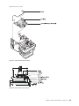
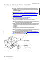
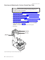
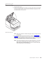
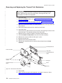
112. Thermal Print Mechanism . . . . . . . . . . . . . . . . .
113. Thermal Paper Switch Adjustment . . . . . . . . . . . . . .
114. Paper Loading Path . . . . . . . . . . . . . . . . . . .
115. Printhead and Print Line Area. . . . . . . . . . . . . . . .
.
.
.
.
.
.
.
.
.
.
.
.
.
.
.
.
.
.
.
.
.
.
.
.
.
.
.
.
.
.
.
.
.
.
.
.
.
.
.
.
.
.
.
.
.
.
.
.
.
.
.
.
.
.
.
.
.
.
.
.
.
.
.
Figures
.
.
.
.
.
.
.
169
170
171
172
176
190
191
xxi
updated October 30, 2001
xxii
SureMark Hardware Service
updated October 30, 2001
Part 1. General Information
This section contains information that applies to all SureMark printers.
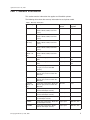
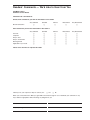
The following table shows the warranty information for each printer model.
Table 1. Warranty Information
Machine type
Description
Warranty
service
Warranty
upgrade
4610-TI3
Attaches to the IBM 4694/4800.
RS232, RS485, USB (Pearl white
covers)
IOR 24x7
none
4610-TI4
Attaches to the IBM 4694/4800.
RS232, RS485, USB (Pearl white
covers)
IOR 24x7
none
4610-TI5 (DBCS Attaches to the IBM 4694/4800.
– AP only)
RS232, RS485, USB (Pearl white
covers)
IOR 24x7
none
4610-TM6
Attaches to the IBM 4694/4800.
RS232, RS485, USB (Pearl white
covers)
IOR 24x7
none
4610-TM7
(DBCS – AP
only)
Attaches to the IBM 4694/4800.
RS232, RS485, USB (Pearl white
covers)
IOR 24x7
none
4610-TF6
TM6 with iron gray covers to match
4840
Depot repair
IOR 24x7 IOR
9x5
4610-TF7
TM7 with iron gray covers to match
4840
Depot repair
IOR 24x7, IOR
9x5
4610-IF6
Functionally equivalent to TF6 with
iron gray covers but with IOR
warranty
IOR 24x7
none
4610-TG3
Functionally equivalent to Model TI3
with iron gray covers to match the
IBM 4840
IOR 24x7
none
4610-TG4
Functionally equivalent to Model TI4
with iron gray covers to match the
IBM 4840
IOR 24x7
none
4610-TG5
(DBCS – AP
only)
Functionally equivalent to Model TI5
with iron gray covers to match the
IBM 4840
IOR 24x7
none
4610-DG3
Functionally equivalent to Model
TG3 but with Depot warranty
Depot repair
IOR 24x7, 9x5
4610-DG4
Functionally equivalent to Model
TG4 but with Depot warranty
Depot repair
IOR 24x7, 9x5
4610-DI3
Functionally equivalent to Model TI3
but with Depot warranty
Depot repair
IOR 24x7, 9x5
4610-DI4
Functionally equivalent to Model TI4
but with Depot warranty
Depot repair
IOR 24x7, 9x5
4610-DM6
Functionally equivalent to Model
TM6 but with Depot warranty
Depot repair
IOR 24x7, 9x5
© Copyright IBM Corp. 1998, 2001
1
updated October 30, 2001
Note: IOR 24x7 is IBM onsite repair 24 hours times seven days per week. 9x5 is
nine hours per day for five days per week.
2
SureMark Hardware Service
updated October 30, 2001
Chapter 1. Overview
|
|
Indicators, Controls, and Stations – Thermal/Impact Printers
Indicator, Control, and Station – Single-Station Printers . .
Communication Mode Selections. . . . . . . . . . .
RS-232 Baud Rate Selection . . . . . . . . . . .
RS-232 XON/XOFF Mode Selection . . . . . . . .
RS-232/RS-485 Selection . . . . . . . . . . . .
Emulation Mode Selection . . . . . . . . . . . .
USB Selection . . . . . . . . . . . . . . . . .
Power Supply Connections . . . . . . . . . . . . .
Printer Mechanism Overviews . . . . . . . . . . .
.
.
.
.
.
.
.
.
.
.
.
.
.
.
.
.
.
.
.
.
.
.
.
.
.
.
.
.
.
.
.
.
.
.
.
.
.
.
.
.
.
.
.
.
.
.
.
.
.
.
.
.
.
.
.
.
.
.
.
.
.
.
.
. 3
. 4
. 4
. 4
. 6
. 7
. 7
. 7
. 9
. . . . . . . . 10
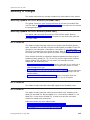
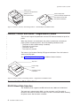
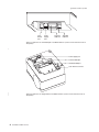
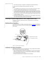
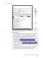
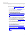
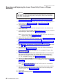
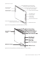
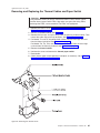
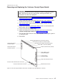
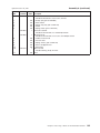
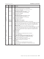
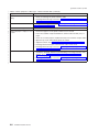
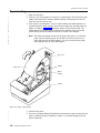
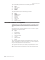
Indicators, Controls, and Stations – Thermal/Impact Printers
There are two triangular-shaped buttons and two LED indicators located on the top
of the printer. The buttons serve multiple functions.
When the Printer Ready LED indicator is on continuously, the printer is online
(connected to the system) and ready for printing.
2
When the indicator blinks, one of the following conditions exists:
v The printer is offline (offline testing is enabled).
v The printer is out of thermal paper.
v The ribbon cover and/or CR paper cover is open.
v The printer has a nonrecoverable home error.
The second LED is the document present indicator. It lights when a document is
inserted far enough into the Document Insert (DI) station to reach the DI sensor.
When this LED blinks, the DI station is waiting for you to insert a document.
The topmost button is the Customer Receipt (CR) paper feed button. Press this
button to advance the CR paper. The lower button is the document feed button.
Press this button to advance the document.
If you simultaneously press both buttons momentarily and then release them, the DI
throat opens. The throat must be open to insert a document from the side. Press
and then release both buttons again to close the throat.
Both buttons are also used to test the printer. See “Offline Tests” on page 25 for
additional button functions.
© Copyright IBM Corp. 1998, 2001
3
updated October 30, 2001
Paper Cover
Customer Receipt Printer
Ribbon Cover
Document Printer
Printer Ready LED
Customer Receipt Feed Button
Document Present LED
Document Feed Button
Figure 1. Indicators, Controls, and Printing Stations – Thermal/Impact SureMark Printers
|
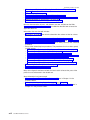
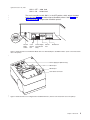
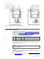
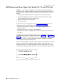
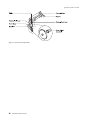
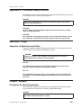
Indicator, Control, and Station – Single-Station Printers
|
|
There is one triangular-shaped button and one LED indicator located on top of the
printer.
|
|
2
|
|
|
When the indicator is on continuously, the printer is powered on and ready for
printing. When the indicator blinks, one of the following conditions exists:
v The printer is offline (offline testing is enabled).
v The printer is out of paper.
v The cover is open.
v The cutter has jammed.
|
|
The button is the Customer Receipt (CR) paper feed button. Press this button to
advance the CR paper.
|
|
See “Offline Diagnostics” on page 161 for additional button functions.
Top cover
Printer ready
LED
Customer receipt
feed button
Figure 2. Indicator, Control, and Printing Station – Single-Station SureMark Printers
Communication Mode Selections
RS-232 Baud Rate Selection
The SureMark printer supports two RS-232 baud rates, 9600 and 19 200 baud.
The baud rate is selected using SW1-1 on the main logic card. The switch is
located on the lower left corner of the logic card and is accessible without removing
the printer covers. Set the switch as follows:
4
SureMark Hardware Service
updated October 30, 2001
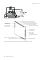
SW1-1 OFF - 9600 baud
SW1-1 ON - 19 200 baud
The card is normally set with SW1-1 in the OFF position, which selects the 9600
baud rate. See Figure 3 for thermal/impact SureMark printers. See Figure 4 and
Figure 5 on page 6for single-station SureMark printers.
|
|
|
1
2
OFF
RS 232
Mode
Switch
Cash
Drawer
Port
Power Supply
Port (RS 232
Only)
RS 232
Port
RS 485 Port
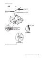
Figure 3. Cable Connectors and RS-232 Mode Switch for Thermal/Impact SureMark Printers. (View is from the bottom
rear of the printer)
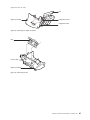
|
Power supply port (RS-232 only)
RS-232 port
RS-485 port
Cash drawer connector
|
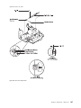
| Figure 4. Cable Connectors for Single-Station SureMark Printers. (View is from the bottom rear of the printer)
Chapter 1. Overview
5
updated October 30, 2001
|
OFF
1 2 3
4
RS-232 mode switches
Cash drawer connector
|
| Figure 5. RS-232 Mode Switch for Single-Station SureMark Printers. (View is from the bottom rear of the printer)
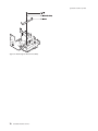
2
Cash drawer cable
Cash drawer cable
Power cord
RS-485 cable
RS-232 cable
2
2 Figure 6. RS-232 and RS-485 Cable Routing for Single-Station SureMark Printers
RS-232 XON/XOFF Mode Selection
The SureMark printer supports RS-232 protocol using DTR/DSR lines to control
data transmission. It also supports XON/XOFF modes where system and printer
software control the flow of data. Select these modes using SW1-2 on the main
logic card. The switch is located on the lower left corner of the logic card and is
accessible without removing the printer covers. Set the switch as follows:
6
SureMark Hardware Service
updated October 30, 2001
SW1-2 OFF - DTR/DSR Control
SW1-2 ON - XON/XOFF Control (Required when using a 3-wire RS-232 cable)
The card is normally set with SW1-2 in the OFF position, which selects DTR/DSR
mode of operation. See Figure 3 on page 5.
RS-232/RS-485 Selection
The SureMark printer will operate using either RS-232 or RS-485 communications
protocol. RS-232 is typically associated with PC systems. The printer contains a
9-pin D-shell connector for RS-232 communications. This connector is located on
the interface card and is accessible under the printer without the need to remove
the printer covers. The connector has the following pin functions:
Pin
Signal
Pin
Signal
1
Not Connected
6
DSR
2
Transmit
7
Not Connected
3
Receive
8
Not Connected
4
DTR
9
Not Connected
5
Signal Ground
RS-485 mode is an IBM proprietary mode of communication. This form of
communication is obtained when attaching the appropriate cable to Port 7 on an
IBM POS system.
|
Emulation Mode Selection
|
Single-station SureMark printers can emulate an Epson single-station printer.
|
|
|
The printer’s mode is selected using SW1-3 on the main logic card (see Figure 4 on
page 5). The switch is located on the logic card next to the cash drawer connector
and is accessible without removing the printer covers. Set the switch as follows:
SW1-3 OFF - SureMark native mode
SW1-3 ON - Epson emulation mode
|
|
For more information about emulation mode, see “Emulating an Epson
Single-Station Printer (Single-Station Only)” on page 21.
|
|
USB Selection
|
|
|
|
|
|
|
Universal serial bus (USB) is an industry standard communication interface. It is
used to attach devices, such as printers, displays, and keyboards, to personal
computers or IBM POS systems that have USB ports. The standard USB port (with
a power brick) is used to attach the SureMark to personal computers. The powered
USB port is used to attach the SureMark to IBM POS systems. See Figure 7 on
page 8 for the thermal/impact SureMark printers and Figure 8 on page 8 for the
single-station SureMark printers.
Chapter 1. Overview
7
updated October 30, 2001
Cash
Drawer
Port
Power
Supply
Port
Powered
USB Port
Standard
USB Port
Figure 7. USB Ports for Thermal/Impact SureMark Printers. (View is from the bottom rear of
the printer)
|
Power supply port
Powered USB port
Standard USB port
Cash drawer connector
|
|
|
Figure 8. USB Ports for Single-Station SureMark Printers. (View is from the bottom rear of
the printer)
8
SureMark Hardware Service
updated October 30, 2001
2
Cash drawer cable
Cash drawer cable
Standard USB cable
Powered USB cable
Power cord
2
2 Figure 9. USB Cable Routing for Single-Station SureMark Printers
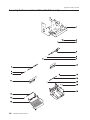
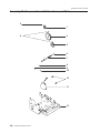
Power Supply Connections
|
|
|
|
|
|
The SureMark printer does not contain a power supply. When the RS-232 or USB
port is used, an external power supply must be attached to the power supply port of
the interface card of the SureMark (see Figure 7 on page 8 or Figure 8 on page 8
for USB mode, and Figure 3 on page 5 or Figure 4 on page 5 for RS-232 mode).
This connector is located under the printer and is accessible without removing the
printer covers. Connector J2 has the following pin functions:
||
Pin
Signal
Pin
Signal
|
1
+24 V dc
2
Not Connected
|
|
3
Ground
|
|
When the RS-485 or powered USB port is used, power is supplied to the printer
from the IBM POS system.
DANGER
Never work on equipment or connect or disconnect signal cables during
periods of lightning activity.
CAUTION:
For your safety, connect equipment requiring electrical power to a correctly
wired and grounded outlet.
Note: For translations of these safety notices, see “Appendix D. Translated Safety
Notices” on page 201.
Chapter 1. Overview
9
updated October 30, 2001
To protect the printer from electrical damage, never plug or unplug the RS-232 or
the RS-485 connector without deactivating the power first. (You can deactivate the
power by either turning off the system unit, or by unplugging the power supply from
the electrical outlet. You can also deactivate a single-station SureMark by turning off
the printer’s power switch.)
|
|
|
|
|
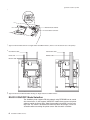
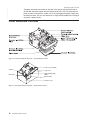
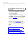
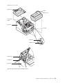
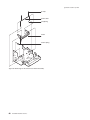
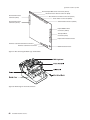
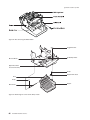
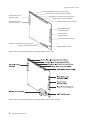
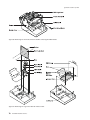
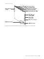
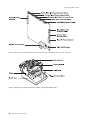
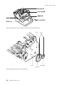
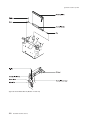
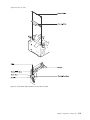
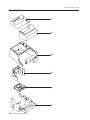
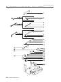
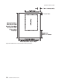
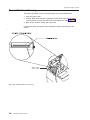
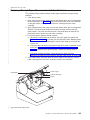
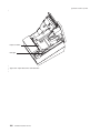
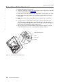
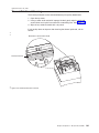
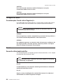
Printer Mechanism Overviews
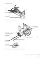
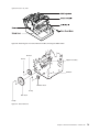
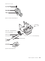
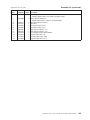
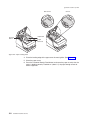
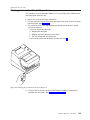
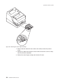
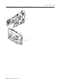
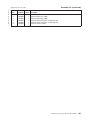
Figure 10. Printer Mechanism Overview – Thermal/Impact Printers
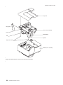
Inner cover assembly
Tear bar
Drive gear
Logic card
Light-emitting diode
(LED)
On/off switch
Interface card
Figure 11. Printer Mechanism Overview – Single-Station Printers
10
SureMark Hardware Service
updated October 30, 2001
Chapter 2. SureMark Installation, Service, and Utility Software
|
|
|
|
|
|
|
|
|
|
|
|
|
Software Adjustments (Models TI1, TI2, TI3, TI4, TG3 and TG4) . . . . .
Using the 4690 Operating System . . . . . . . . . . . . . . .
Using IBM Point-of-Sale Device Diagnostics . . . . . . . . . . .
Using the Reference/Service Diskettes (RS-485 or RS-232 Printers) . .
4610 Fonts and Logos Utility Diskette . . . . . . . . . . . . . .
Proportional Font Conversion Utility . . . . . . . . . . . . . . .
Firmware Update . . . . . . . . . . . . . . . . . . . . . .
Using Firmware Update Diskette . . . . . . . . . . . . . . .
Using POSS For Windows to Update SureMark Printer Firmware (RS-485
and USB Only) . . . . . . . . . . . . . . . . . . . . .
IBM Point-of-Sale Device Diagnostics . . . . . . . . . . . . .
Using 4690 OS 4610 Utility to Update SureMark Firmware . . . . . .
Updating SureMark Firmware Using Temporary RS-232 Attachment . .
Limitation on Updating Firmware . . . . . . . . . . . . . . .
Emulating the IBM Model 3 or Model 4 Printers . . . . . . . . . . .
Enabling Emulation Using Utility Diskettes . . . . . . . . . . . .
Enabling Emulation Using 4690 On-Line Terminal Diagnostics . . . .
Limitations for Emulation . . . . . . . . . . . . . . . . . .
Printing Saved Data . . . . . . . . . . . . . . . . . . . .
Printing Buffer Data – Thermal/Impact Printers . . . . . . . . .
Printing Buffer Data – Single-Station Printers . . . . . . . . . .
Emulating an Epson Single-Station Printer (Single-Station Only) . . . . .
Enabling Epson Emulation. . . . . . . . . . . . . . . . . .
Limitations for Epson Emulation. . . . . . . . . . . . . . . .
MICR Data Parser Sample Code (Models TI2, TI4 and TG4 Only) . . . .
Resources on the Internet . . . . . . . . . . . . . . . . . . .
.
.
.
.
.
.
.
.
.
.
.
.
.
.
.
.
11
11
12
12
15
15
15
16
.
.
.
.
.
.
.
.
.
.
.
.
.
.
.
.
.
.
.
.
.
.
.
.
.
.
.
.
.
.
.
.
.
.
16
17
17
18
18
18
19
19
20
20
20
20
21
21
21
22
22
This chapter describes how to make software adjustments using either the 4690
OS, IBM Point-of-Sale Device Diagnostics (POSS for Windows, RS-485 and USB
only), or diskettes and other resources that are available from the Retail Store
Solutions Web site. See “Resources on the Internet” on page 22 for more
information.
Software Adjustments (Models TI1, TI2, TI3, TI4, TG3 and TG4)
Depending on your operating system, you can use the following to make software
adjustments to the impact (document insert) station of a SureMark printer:
v 4690 Operating System
v IBM POS Device Diagnostics
v Reference/service diskettes
Using the 4690 Operating System
1. Start Utility Mode by pressing S1, typing 9 5, and then pressing S2.
2. When “enter request” is displayed, enter the keying sequence from the table for
the procedure you want to do.
3. Press S2 to advance through the various parts of the printer adjustment steps.
4. Type 9 9 and then press S2 to exit.
© Copyright IBM Corp. 1998, 2001
11
updated October 30, 2001
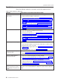
Table 2. Adjustment Procedures Using the 4690 Operating System
Procedure
Keying Sequence
Print Current Adjustment Values - see Figure 12 on page 14.
7, 2, 1, S2
Character Alignment Procedure - see Figure 12 on page 14.
7, 2, 2, S2
DI Front Load Print Line Adjustment - see Figure 12 on
page 14.
7, 2, 3, S2
Backlash Adjustment (Landscape)
7, 2, 5, S2
Engineering Use Only
7, 2, 7, S2
Hardware Setup Option
7, 2, 8, S2
Update Printer Firmware
7, 2, 9, S2
Using IBM Point-of-Sale Device Diagnostics
|
This utility is for RS-485 and USB only.
1. Start the IBM Point-of-Sale Device Diagnostics application from the Windows
Start menu.
2. Click 4610 Printer.
3. Click Device Utility.
4. Select the appropriate tab for the desired adjustment:
2
Table 3. Adjustment Procedures Using the Point-of-Sale Device Diagnostics
2
Procedure
Tab
2
Character Alignment
Adjustments
2
DI Front Load Adjustment
Adjustments
2
Backlash Adjustment (Landscape)
Adjustments
2
Engineering Use Only
Read MCT
2
Firmware Update
Firmware Update
2
Reset Thermal Print Head Statistics
Reset Stats
2
Reset CR Motor Statistics
Reset Stats
2
Reset Impact Print Head Statistics
Reset Stats
2
Reset DI Motor Statistics
Reset Stats
2
2
Reset Transport Motor Statistics
Reset Stats
Using the Reference/Service Diskettes (RS-485 or RS-232 Printers)
1. Load the reference/service diskette. See the hardware service manual for your
system for reference/service diskette procedures.
2. Select Test Menu.
3. Select Run POS Device Tests for an RS-485 connection. Select RS232 4610
Printer Test for an RS-232 connection.
4. If another system is attached, select the system whose printer you want to
adjust. This is unnecessary when there is no other system attached.
2
2
2
5. Select Printer Utilities.
6. Select the adjustment you want to make from the menu.
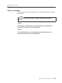
v Print current adjustment values - see Figure 12 on page 14.
v Character alignment procedure - see Figure 12 on page 14.
v DI front load print line adjustment - see Figure 12 on page 14.
2
12
SureMark Hardware Service
updated October 30, 2001
2
2
2
v
v
v
v
Document landscape adjustment - see Figure 12 on page 14.
Engineering use only
Change 4610 Model Configuration
Reset printer statistics
Note: Because the first four adjustments affect only the document insert
station, they are not displayed as selectable options if the printer is a
single-station SureMark.
7. Follow the instructions that are printed on the printer or displayed on the screen.
8. Press S1 (Esc on the Enhanced A/N Keyboard) to return to the previous menu.
Chapter 2. SureMark Installation, Service, and Utility Software
13
updated October 30, 2001
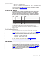
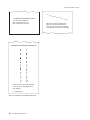
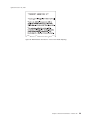
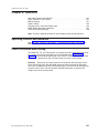
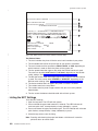
TL1
CURRENT ADJUSTMENT VALUES
H 5 = Character alignment
TL5 = Top line front insert
BL3 = Bottom line top insert
CHARACTER ALIGNMENT PROCEDURE
Press the key (1-9) that corresponds
to the pair of H's that appear to be
most aligned
5 = selected line
Figure 12. Adjustment and Alignment Printouts
14
SureMark Hardware Service
TL2
TL3 TL4
TL5
TL6
TL7
TL8
TL9
Measure from the top edge of this
paper to the top of each print line.
Press the key (1-9) that corresponds
to the print line that is closest to 5MM.
updated October 30, 2001
|
4610 Fonts and Logos Utility Diskette
|
|
|
This utility is for both RS-232 and RS-485 operation. You can download the utility
from the Retail Store Solutions Web site. See “Resources on the Internet” on
page 22 for more information.
|
|
|
|
|
|
|
The utility program allows you to perform the following functions:
v Update printer firmware
v Configure the printer model
v Create, edit, and download user-defined character fonts, logo images, and
messages
v Download proportional fonts (not supported for models TI1 and TI2)
v Convert fonts and logo files from impact to thermal
|
|
|
|
|
From the same Web site, you can also download the following sample files for use
with the utility program:
v User-defined characters file
v Message file
v Logo file
|
|
Proportional Font Conversion Utility
|
|
|
As part of its support for proportional fonts, IBM provides three TrueType fonts and
a utility that you can use to convert the fonts to files that the SureMark printer can
use.
|
|
|
The application and instructions for downloading the converted fonts are available
from the Retail Store Solutions Web site. See “Resources on the Internet” on
page 22 for more information.
|
|
|
|
|
Note: You might have TrueType fonts other than those supplied by IBM on your
system. Before using the conversion utility to convert and download any
non-IBM fonts for use by the SureMark printer, you must confirm that you
have received authorization from the owner of the fonts to convert and
download the fonts.
|
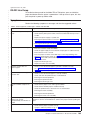
Firmware Update
The SureMark printer has the capability to receive SureMark firmware updates from
the host system unit to which it is attached for either RS-485 attached, RS-232, or
USB-attached SureMark printers.
|
The following mediums can be used to update the SureMark firmware:
v Firmware update diskettes
v POSS for Windows 4610 Printer Firmware Update Program
v 4690 OS 4610 Utility Program
v Alternative 4610 firmware update method via RS-232 attachment cable
Use the appropriate procedure that follows to update the SureMark firmware, after
downloading the latest level software from the Retail Store Solutions Web site (see
“Resources on the Internet” on page 22).
Chapter 2. SureMark Installation, Service, and Utility Software
15
updated October 30, 2001
Using Firmware Update Diskette
|
|
|
Use a firmware update diskette to update the firmware in configurations when the
SureMark is attached by either an RS-232 or RS-485 cable, and the system has a
floppy diskette drive, a PC keyboard, and display.
|
|
|
|
1. Download the latest level of firmware update diskette from the Web (see
“Resources on the Internet” on page 22). You can select from several update
methods, including attended, unattended, and automatic.
2. Insert the firmware update diskette in drive A.
3. Power on the system unit that has the SureMark attached by either an RS-232
or RS-485 cable.
4. Select RS-485 or RS-232 connection.
5. Follow the messages displayed to complete the firmware update.
a. Press Enter (OK) at the logo screen to proceed.
2
b. Choose connection type (RS-485 or RS-232). For RS-232 connections, also
make the following selections (refer to the communications mode selections
switches, located on the bottom rear of the SureMark printer, to determine
the following selections):
v Communications port (COM1, COM2, COM3, COM4)
v Baud Rate (9600 or 19 200)
v Control Flow (DTR/DSR or XON/XOFF)
c. Press Enter (OK) to proceed.
d. Press F10 (Menu).
e. Select O (Operations).
f. Select A (Advanced Options).
g. Select U (Update Firmware).
h. Press Enter twice to select the desired firmware image file (usually only the
latest firmware image file is available for selection).
i. Press Enter (YES) again to commit to firmware update.
j. The Information screen will display the update percent completed.
Note: The SureMark flash update will take several minutes. Do NOT power
off the host system or the SureMark printer after the update has
started.
6. After the firmware update is complete, the SureMark printer will be reset.
a. Press Enter (OK) to confirm.
b. Press Alt-X (Exit).
c. Press Enter to exit.
7. Remove the diskette from drive A.
8. Press Ctrl-Alt-Del to reboot the system.
Using POSS For Windows to Update SureMark Printer Firmware
(RS-485 and USB Only)
Windows users with SureMark printers can use the POSS for Windows 4610 Printer
Firmware Update program (AIPFLD46.EXE) to update SureMark firmware. For
additional information, refer to the POSS Programming Reference and User’s
Guide.
Note: POSS Suite V1.0.0 or greater is required to use this utility.
16
SureMark Hardware Service
updated October 30, 2001
2
2
|
|
1. Download the latest SureMark firmware update image file from the Web. The file
is:
v AIP46MC.HEX for models TI1 and TI2
v AIP46MCH.HEX for models TI3, TI4, TG3 and TG4. This file is also for
single-station printers with 512KB or 8MB of memory
v AIP46MCD.HEX for models TI3, TI4,, TG3, TG4, TF6, and TM6 with the
2-MB memory option.
2. Copy the latest SureMark firmware update image file to the C:\POS\BIN
directory. Because the file in the directory is more current than the old file, the
firmware will be automatically updated when the system is powered off and
back on.
3. To update the firmware manually, enter the following command to update the
SureMark firmware:
AIPFLD46.EXE -S slot_number -P port_number -F microcode_file [-Q]
where:
slot_number
SureMark slot number, usually = 1. The slot number must be specified
with decimal values only; hexadecimal values are not accepted.
port_number
SureMark port number specified with a decimal value, usually = 17
microcode_file
Either C:\POS\BIN\AIP46MC.HEX, C:\POS\BIN\AIP46MCH.HEX, or
C:\POS\BIN\AIP46MCD.HEX
-Q
Quiet mode installation (no progress information)
4. The SureMark flash update will take several minutes.
IBM Point-of-Sale Device Diagnostics
USB printers connected to one of the SurePOS 700 Series systems can use the
IBM Point-of-Sale Device Diagnostics to update the SureMark firmware. See IBM
SurePOS 700 Series: System Reference for more information on the IBM
Point-of-Sale Device Diagnostics.
Using 4690 OS 4610 Utility to Update SureMark Firmware
If you use the 4690 OS with SureMark printers that are attached to medialess
systems with RS-485 or USB connections, you can use the 4610 Utility Program
function of the 4690 OS to update SureMark firmware.
Note: 4690 OS level 9910 or greater is required to use this utility.
1. To invoke the utility, press Ctrl S1, 95, Ctrl S2.
2. Press 729, Ctrl, S2 at the ENTER REQUEST prompt.
3. Press 1, Ctrl S2 to continue.
4. Message T7175 will display to confirm flash update has started.
5. The SureMark flash update will take several minutes. Message ″T9514 Enter
Request″ displays after the SureMark flash update completes.
6. Enter 99, Ctrl S2 to end the SureMark utility.
Chapter 2. SureMark Installation, Service, and Utility Software
17
updated October 30, 2001
Updating SureMark Firmware Using Temporary RS-232 Attachment
|
|
|
|
To use the firmware update diskettes to update SureMark firmware for
configurations that do not have a floppy diskette drive and PC display and
keyboard, you must provide a temporary RS-232 attachment to a host PC that does
have a floppy diskette drive.
2
2
Note: A 4610 firmware update diskette at V3.10 or greater is required to use this
utility.
Before starting the firmware update, you must obtain the following parts:
v RS-232 attachment cable, either 2 meters in length (P/N 86H2192) or 4 meters in
length (P/N 86H2195).
v SureMark Power Supply (for RS-232 configurations only), P/N 42H1176.
If the SureMark is currently attached to a host system unit that does not support a
floppy diskette drive, use the following procedure to temporarily connect the printer
to a host PC that has a floppy diskette drive, RS-232 port, PC keyboard and
display.
1. Disconnect the SureMark (RS-485 #7) attachment cable and temporarily
connect a RS-232 attachment cable to the SureMark.
2. Connect the SureMark via the RS-232 port connector to an alternate host PC
that has a floppy diskette drive.
3. Follow the procedure in “Using Firmware Update Diskette” on page 16, starting
with Step 1, to complete the SureMark firmware update.
4. Reconnect the SureMark to the original host system unit using the original
attachment cables.
Limitation on Updating Firmware
The following limitation must be considered when updating firmware on the
SureMark printer:
v SureMark firmware update cannot be performed if the printer currently has Model
4 emulation enabled. If emulation is enabled, temporarily disable Model 4
emulation, then start the SureMark firmware update. After the firmware update is
complete, re-enable Model 4 emulation. See “Emulating the IBM Model 3 or
Model 4 Printers” for additional information.
Emulating the IBM Model 3 or Model 4 Printers
It is possible to emulate the IBM Model 3 or Model 4 printer with the SureMark
printer. You must change the configuration to enable the SureMark to emulate the
Model 3 or Model 4 printers.
The following mediums can be used to set up Model 3 or Model 4 emulation:
v For systems with diskette drives, use the Font and Logos Utility Diskette or the
Configure MCT Utility Diskette (see “Enabling Emulation Using Utility Diskettes”
on page 19). Download the latest level diskette from the Retail Store Solutions
Web site. See “Resources on the Internet” on page 22 for more information.
v For medialess systems using the 4690 OS, use the 4690 OS Online Terminal
Diagnostics (see “Enabling Emulation Using 4690 On-Line Terminal Diagnostics”
on page 19).
2
2
2
2
18
SureMark Hardware Service
updated October 30, 2001
Enabling Emulation Using Utility Diskettes
The following information is also available in the 4610MOD4.TXT file on the
diskette.
Note: All SureMark firmware levels for models TI3, TI4, TG3, TF6 and TM6 support
emulation.
To set up Model 3 or Model 4 emulation using the Font and Logos Utility Diskette or
the Configure MCT Utility Diskette:
1. Insert the utility diskette in drive A.
2. Power on the system unit.
3. Select MOD4 when the menu is displayed.
4. Perform the specified steps to either enable or disable emulation.
To enable when emulation is currently disabled:
1. Select one of the following:
v Model 4 emulation with Offline mode disabled
v Model 4 emulation with Offline mode enabled
The printer is reconfigured.
2. Press Ctrl-Alt-Delete to reboot the system. The system IPLs.
To disable when emulation is currently enabled:
1. Select Disable Model 4 emulation.
2. Enter Ctrl-Alt-Delete to reboot the system. The system IPLs.
Enabling Emulation Using 4690 On-Line Terminal Diagnostics
Note: 4690 OS Version 1 level 9740 or greater is required to use this utility.
To set up Model 3 or Model 4 emulation using the 4690 On-Line Terminal
Diagnostics:
1. To invoke the utility, press Ctrl S1, 95, Ctrl S2.
2. At the ENTER REQUEST prompt, press 728, Ctrl, S2. This brings up the
function to switch the mode of the printer.
3. Perform the specified steps to either enable or disable emulation. The operating
system recognizes the current state of printer emulation and displays the
appropriate prompts.
To enable emulation:
1. If using the printer’s integrated MICR reader, select TI2, TI4 or TG4. Otherwise,
select TI1, TI3 or TG3.
2. At the Activate Model 3/4 Emulation 1=N, 2=Y, S2 prompt, enter 2 to enable
Model 3/4 emulation.
3. At the Using EJ in Offline Mode? 1=N, 2=Y, S2 prompt, select Y if you want to
store all the journal data in the printer’s flash memory.
To disable emulation:
1. At the Disable Mod 3/4 Emulation 1=N, 2=Y, S2 prompt, enter 2 to disable
Model 3/4 emulation.
Chapter 2. SureMark Installation, Service, and Utility Software
19
updated October 30, 2001
Limitations for Emulation
The following limitations must be considered when using the SureMark printer to
emulate the Model 3 or Model 4 printer.
v Printing the face of checks requires application changes (franking the back of
checks should not).
v Printing wide documents may require changes. The document station on the
Model 4 printer supports 86 characters, the SureMark supports 47 characters.
v Journal commands can be ignored or stored in the printer’s flash memory. This
needs to be decided when the printer is initially configured.
v There is no top document registration (documents must be inserted from the
front).
v User-defined special characters are not supported.
v Because SureMark models TF6 and TM6 do not have a document insert station,
they do not emulate document station commands.
v Emulation mode does not support the Model 4A double-byte character set.
v For RS-485, emulation mode is currently only supported on 4690 OS and DOS
systems. For USB, emulation mode is currently only supported on 4690 OS.
Emulation is not supported for RS-232.
|
|
|
Printing Saved Data
|
|
|
|
|
|
When the printer is offline in Model 3/4 emulation mode and the option for storing
data to the printer was selected, it is possible to fill up the printer flash memory.
When the memory is full, a printer error indicates the journal station is out of paper.
You can empty the printer buffer by printing out the data that is stored in the flash
memory. The data prints on the customer receipt station. The data in the buffer is
erased only after the last line of data is printed.
|
|
Note: If the SureMark has the 2-MB option installed, up to 3 rolls of paper might be
needed to print all the electronic journal data.
|
|
Printing Buffer Data – Thermal/Impact Printers
To print the buffer data from the beginning:
1. Press and hold both buttons. When the printer ready indicator begins blinking,
release both buttons.
2. Press and release both buttons again.
|
|
|
|
|
|
|
|
|
|
Notes:
1. If the SureMark printer encounters an error (for example, the paper runs out or
the cover is opened) while printing the data, the data remains intact.
2. To stop printing the data, open and close the ribbon cover. When you are ready
to print the data, use the procedure above to restart printing from the beginning.
|
|
|
Printing Buffer Data – Single-Station Printers
|
|
|
2. Press and hold the paper feed button for 5 seconds.
3. The LED will show one short blink, accompanied by a beep, followed by a
1-second pause.
|
4. Press and hold the paper feed button for 5 seconds.
3. To stop printing and restart at the current position, open and close the paper
cover. Printing immediately restarts.
To print the buffer data from the beginning:
1. Open the top cover. The LED will flash quickly.
20
SureMark Hardware Service
updated October 30, 2001
|
|
5. The LED will change to a long blink. The beeper will sound continuously.
6. Close the cover to begin printing the electronic journal data.
|
|
|
|
|
|
Notes:
1. If the SureMark printer encounters an error (for example, the paper runs out or
the cover is opened) while printing the data, the data remains intact.
|
|
|
|
|
|
|
|
|
2
2
2
|
|
2. To stop printing the data, open the top cover, turn the printer power switch ON,
turn the printer power switch OFF, and close the top cover. When you are ready
to print the data, use the procedure above to restart printing from the beginning.
3. To stop printing and restart at the current position, open and close the top cover.
Printing immediately restarts.
4. Pressing and releasing the paper feed button a third time before closing the top
cover will cause the printer to return to normal mode.
Emulating an Epson Single-Station Printer (Single-Station Only)
Emulation of an Epson single-station printer is supported on the single-station
SureMark printers.
Enabling Epson Emulation
To enable emulation of an Epson single-station printer on a single-station SureMark
printer, you must set switch 3 on the main logic card. See Figure 13 for the location
of the switch.
OFF
1 2 3
4
RS-232 mode switches
Cash drawer connector
|
|
|
|
|
|
|
|
|
|
Figure 13. Switch for Epson Emulation
Limitations for Epson Emulation
The following limitations must be considered when using a single-station SureMark
printer to emulate an Epson single-station printer:
v Logos and downloadable characters are supported in emulation mode. However,
because the Epson printer prints at 150 dpi and the SureMark prints at 200 dpi,
the emulated printout will be smaller.
v Emulation of page mode is not supported on the SureMark.
Chapter 2. SureMark Installation, Service, and Utility Software
21
updated October 30, 2001
v Epson supports the Select paper sensor to stop printing command. IBM does not
support a low paper sensor.
|
|
|
MICR Data Parser Sample Code (Models TI2, TI4 and TG4 Only)
The MICR data parser download package includes:
v Sample source code (in C) that contains algorithms for parsing MICR data from a
check.
v An exception data file that is used with the parsing code. You can edit this file to
add new check formats, if necessary.
Refer to the README file in this download package for additional information.
Resources on the Internet
The IBM Retail Store Solutions Web site at
http://www.ibm.com/solutions/retail/store contains publications for the
SureMark Printer. The Web site also provides access to diskettes, drivers, and
miscellaneous documentation, such as README files and information about OEM
papers that have been certified.
Select Support at the left on the main page of the Web site, then select IBM
SureMark Printer. The displayed page contains links both to documentation and to
diskettes and drivers that you can download for the SureMark printers.
22
SureMark Hardware Service
updated October 30, 2001
Part 2. Models TI1, TI2, TI3, TI4, TG3 and TG4
This part contains repair/replacement, adjustment, and daily operational procedures
for models TI1, TI2, TI3, TI4, TG3 and TG4. It also contains the parts catalog for
these models.
© Copyright IBM Corp. 1998, 2001
23
updated October 30, 2001
24
SureMark Hardware Service
updated October 30, 2001
Chapter 3. Problem Determination
Offline Tests . . . . . . . . . . . . . . . . . . . . . . . . . . 25
Customer Receipt Test . . . . . . . . . . . . . . . . . . . . . 25
Document Insert Test . . . . . . . . . . . . . . . . . . . . . 26
MICR Reader and Check Flipper Test (Models TI2, TI4, and TG4 Only) . . . 28
Symptoms . . . . . . . . . . . . . . . . . . . . . . . . . . 30
Customer Receipt Paper Movement and Cutter Problems . . . . . . . . . 35
FRU Removal and Replacement . . . . . . . . . . . . . . . . . . 37
Removing and Replacing the Top, Paper, and Ribbon Covers. . . . . . . 37
Removing and Replacing the Top Cover Operator Buttons . . . . . . . . 41
Removing and Replacing the Document Insert Lower Cover and Flipper
Cartridge . . . . . . . . . . . . . . . . . . . . . . . . . 42
Removing and Replacing the Printhead . . . . . . . . . . . . . . . 43
Removing and Replacing the Home Sensor . . . . . . . . . . . . . 44
Removing and Replacing the Ribbon Drive Assembly. . . . . . . . . . 45
Removing and Replacing the Tensioner . . . . . . . . . . . . . . . 47
Removing and Replacing the Printhead Carriage Assembly . . . . . . . 48
Removing and Replacing the Transport Motor . . . . . . . . . . . . 52
Removing and Replacing the Printhead Cable . . . . . . . . . . . . 55
Removing and Replacing the Document Insert Sensor Assembly . . . . . 56
Removing and Replacing the Document Insert Platen Assembly . . . . . . 59
Removing and Replacing the MICR Read Head . . . . . . . . . . . . 61
Removing and Replacing the Lower Forms Entry Frame or Flipper Assembly 64
Removing and Replacing the Document Insert Backup Roller and Insert
Lever Assembly . . . . . . . . . . . . . . . . . . . . . . . 68
Removing and Replacing the DI Feed Roller . . . . . . . . . . . . . 71
Removing and Replacing the Switch Card and Printhead Spacer . . . . . 75
Removing and Replacing the Main Logic Card and Cable-Attached Interface
Card (Models TI1 and TI2) . . . . . . . . . . . . . . . . . . . 76
Removing and Replacing the Main Logic Card and Connector-Attached
Interface Card (Models TI3, TI4, TG3, and TG4) . . . . . . . . . . . 79
Removing and Replacing the Thermal Cables and Paper Switch . . . . . 81
Removing and Replacing the Thermal Latch . . . . . . . . . . . . . 84
Removing and Replacing the Thermal Drag Strip . . . . . . . . . . . 86
Removing and Replacing the Thermal Printhead Assembly. . . . . . . . 88
Removing and Replacing the Thermal Platen Assembly . . . . . . . . . 91
Removing and Replacing the Customer Receipt Motor . . . . . . . . . 92
Removing and Replacing the Rotating Cutter Blade and Thermal Guide . . . 93
Removing and Replacing the Cutter Gears and Cutter Clutch . . . . . . . 94
Removing and Replacing the Customer Receipt Paper Guide. . . . . . . 96
Removing and Replacing the Customer Receipt Paper Bucket . . . . . . 97
Removing and Replacing the Document Insert Motor and Gears . . . . . 100
Offline Tests
The following offline tests are used as diagnostic tools to ensure the printer is
operating correctly.
Customer Receipt Test
1. Press and hold both buttons to enter offline mode. When the Printer Ready
indicator begins blinking, release both buttons.
2. Press and release the Customer Receipt Feed button to start this test.
© Copyright IBM Corp. 1998, 2001
25
updated October 30, 2001
3. See Figure 14 on page 27 and verify that your printer has printed correct
information for your model and configuration:
v MICR reader enabled and check flipper enabled (Model TI2, Model TI4, or
Model TG4)
v Double-byte character sets enabled (Model TI5 and TG5)
v 2-MB card with user flash storage enabled (Models TI3, TI4, TG3, and TG4)
v 2-MB card in single-byte mode (Model TI5 and TG5)
v RS-232, RS-485 or USB serial interface
v Applicable parameters for RS-232 communications:
– 9600 or 19 200 baud rate
– DTR/DSR or XON/XOFF control
v A solid line should appear as the last line of the test pattern.
If any characters that appear in Figure 14 on page 27 are missing from the test
pattern you print, or if the solid line is missing, go to “Symptoms” on page 30.
Document Insert Test
1. Insert a document in the Document Insert station. The Document Present
indicator should come on.
v If the Document Present indicator does not come on, realign the document. If
the Document Present indicator still does not come on, go to “Document
Sensor Threshold Reset” on page 117.
v If pressing the Document Feed button does not feed the document, go to
“Symptoms” on page 30.
2. Press and hold both buttons to enter offline mode. When the Printer Ready
indicator begins blinking, release both buttons.
3. Press and release the document feed button to print the test pattern. The test
pattern includes all printable characters in the resident code page, printed in the
default font.
4. See Figure 14 on page 27 and verify that your printer has printed correct
information for your model and configuration:
v Model type (MICR reader enabled, check flipper enabled for Model TI2, TI4,
or Model TG4).
v Communication options (RS-232 or RS-485).
v RS-232 parameters, if applicable.
v A solid line should appear as the last line of the test pattern.
If any characters that appear in Figure 14 on page 27 are missing from the test
pattern you print, or if the solid line is missing, go to “Symptoms” on page 30.
26
SureMark Hardware Service
updated October 30, 2001
|
The Printers S/N is 1234567
1
Microcode EC level is 30
Serial Interface: RS232
Serial Interface : 19.2K Baud, XON / XOFF
MICR reader enabled
Check Flipper enabled
|"#$%&'()*+,-./0123456789:;<->?ABCDEFGHIKJK
LMNOPQRSTUVWXYZ[\]^_ abcdefghijklmnopqrstuvw
xyz{|}~.CüéâäàåcêëèïîìÄÅÉæÆôöòûùÿÖÜø£ØSsáíóú
ÁÑGg¿ · · · · ¡ · ·
ÁÂÀ I·
¢ · · · · · · · · ãÃ
·
^ ` õÕµþÞUUUyY±÷
` ^` ` `
H I III · · · · · · · · · · · · · õ Ð ÊËÈÍÎÏÌÓßOO
·
2
3
4
Cuts:
125850
CR Characters Printed:
142834
CR Motor Steps:
659340
CR Cover Openings:
593
DI Characters Printed:
DI Feed Motor Steps:
DI Transpor t Motor Passes:
DI Home Errors:
DI Cover Openings:
DI Documents Inser ted:
MICR Reads:
High Interference MICR Reads:
MICR Read Failures:
,5
6
7
8
9
|
|
|
Figure 14. Offline Printer Test Pattern (Thermal/Impact SureMark Printers). This pattern is
from the customer receipt (CR) station.
Test Pattern Notes:
1. The serial number that prints will be the actual serial number of your printer.
|
|
2
2
2. The microcode level will be the actual level of your printer’s microcode.
3. The serial interface will be specified as RS232, RS485, or USB, depending on
which interface is used to attach the printer to the system unit.
4. The line speed information appears only when the RS-232 interface is used.
The value can be either 9.6K baud or 19.2K baud, depending on the RS-232
switch settings. (See “Communication Mode Selections” on page 4.)
5. The RS-232 control mode information appears only when the RS-232 interface
is used. The value can be either DTR/DSR or XON/XOFF, depending on the
RS-232 switch settings. (See “Communication Mode Selections” on page 4.)
6. The feature enabled lines will appear only when the feature is installed.
7. These lines break at different points for the test pattern printed in the document
insert (DI) station.
8. This section contains printer usage statistics that you can use for problem
determination. (This information is not printed on models TI1 and TI2.)
9. The line across the bottom should be solid with no blank spaces.
Chapter 3. Problem Determination – Models TIx
27
updated October 30, 2001
MICR Reader and Check Flipper Test (Models TI2, TI4, and TG4 Only)
Attention: If the printer is in Model 3 or 4 emulation mode, failure to perform
these steps in the sequence shown will cause the entire electronic journal to print
on the CR station. Printing the electronic journal erases the information from flash
storage.
1. Insert the check face down with the magnetic ink characters to the right.
2. Press and hold both buttons to enter offline mode. When the printer ready
indicator begins blinking, release both buttons.
3. Press and release both buttons again.
4. Remove the check.
Characters that match the magnetic ink characters are printed on the customer
receipt and the check is flipped over. Go to “Symptoms” on page 30 if:
v Characters that match the magnetic ink characters are not printed on the
customer receipt.
v Question marks or an ’X’ appear in the printed line.
v Characters that match the magnetic ink characters are printed but the check is
not flipped.
If the Model TI2, TI4, or TG4 detects noise, it prints a message on the customer
receipt below the magnetic characters from the check (Figure 15 and Figure 16 on
page 29 are examples - actual numbers may vary). The message shows noise
characteristics. You can use the noise level to position your printer to minimize
outside interference with the MICR reader.
Sources of electromagnetic noise (for example, displays, security towers, and other
sources) can interfere with the MICR reader read head. If the printer shows an
external noise source, rearrange the printer to make the noise source as far away
as possible from the right side of the printer. This may eliminate the external noise.
Figure 15. MICR Reader Test Results – Good Noise Level
28
SureMark Hardware Service
updated October 30, 2001
Figure 16. MICR Reader Test Results – Noise Level Needs Adjusting
Chapter 3. Problem Determination – Models TIx
29
updated October 30, 2001
Symptoms
Review the following symptoms or messages and take the suggested actions.
Table 4. Printer Symptoms or Messages
Symptom
Repair Actions Listed in Most Likely Order of Failure
Printer does not power ON (Both
LEDs are off).
1. Check for a good connection and that the printer is plugged in.
2. Replace the power supply or system unit.
3. Exchange the printer interface card. Go to “Removing and Replacing the
Main Logic Card and Cable-Attached Interface Card (Models TI1 and TI2)”
on page 76 or “Removing and Replacing the Main Logic Card and
Connector-Attached Interface Card (Models TI3, TI4, TG3, and TG4)” on
page 79.
4. Exchange the main logic card. Go to “Removing and Replacing the Main
Logic Card and Cable-Attached Interface Card (Models TI1 and TI2)” on
page 76 or “Removing and Replacing the Main Logic Card and
Connector-Attached Interface Card (Models TI3, TI4, TG3, and TG4)” on
page 79.
Printer indicators do not come on.
1. Check that the printer is plugged in and has power.
2. Check for a broken LED.
3. Exchange the switch card. Go to “Removing and Replacing the Switch Card
and Printhead Spacer” on page 75.
4. Exchange the main logic card. Go to “Removing and Replacing the Main
Logic Card and Cable-Attached Interface Card (Models TI1 and TI2)” on
page 76I or “Removing and Replacing the Main Logic Card and
Connector-Attached Interface Card (Models TI3, TI4, TG3, and TG4)” on
page 79.
Printer Ready LED is blinking.
1. Press the customer receipt feed button.
2. Check the paper supply to ensure that the receipt paper is loaded correctly.
3. Ensure that the covers are closed.
4. Adjust the thermal paper switch. Go to “Thermal Paper Switch Adjustment”
on page 116.
5. Run the printer offline tests. Go to “Offline Tests” on page 25.
Customer receipt (thermal) does
not advance paper.
1. Check to see if the thermal paper is jammed or loaded incorrectly.
Customer receipt (thermal) is
missing character dots.
1. Check to see if the thermal paper is correctly installed.
2. Go to “Customer Receipt Paper Movement and Cutter Problems” on page 35
to isolate the problem.
2. Check to see if the printhead cables are seated correctly. Go to “Removing
and Replacing the Thermal Cables and Paper Switch” on page 81.
3. Check and clean the printhead area, if contaminated.
4. Adjust the printhead. Go to “Thermal Printhead Adjustment” on page 114.
5. Exchange the CR (thermal) latch and print assembly. Go to “Removing and
Replacing the Thermal Latch” on page 84.
Customer receipt (thermal)
randomly missing rows of print,
accompanied by one thin line on
receipt.
30
SureMark Hardware Service
Problem is caused by operator pulling the receipt out of the printer. Instruct
operators to use the CR feed button to advance the paper, instead of pulling the
paper.
updated October 30, 2001
Table 4. Printer Symptoms or Messages (continued)
Symptom
Repair Actions Listed in Most Likely Order of Failure
Cutter does not work correctly.
1. Check that the paper is loaded correctly.
2. Check that the clear plastic paper guide is in the correct position.
3. Perform the Cutter Blade Run-In Procedure. Go to “Cutter Blade Run-In” on
page 111.
4. If paper is folded or partially cut, go to “Customer Receipt Paper Movement
and Cutter Problems” on page 35.
DI print has missing dots.
1. Ensure the nose of the printhead is clear of debris.
2. Check the printhead platen gap adjustment. Go to “Printhead Platen Gap
Adjustment” on page 108.
3. Check the printhead cable for continuity. Unplug the cable at the printhead
and logic card for access.
4. Check the printhead for bent print wires. Remove the printhead (see
“Removing and Replacing the Printhead” on page 43) for access.
5. Exchange the printhead. Go to “Removing and Replacing the Printhead” on
page 43.
6. Exchange the logic card. Go to “Removing and Replacing the Main Logic
Card and Cable-Attached Interface Card (Models TI1 and TI2)” on page 76 or
“Removing and Replacing the Main Logic Card and Connector-Attached
Interface Card (Models TI3, TI4, TG3, and TG4)” on page 79.
7. Exchange any or all of the following components: DI gears, DI feed roll shaft
assembly, and feedroll assembly. Go to “Removing and Replacing the
Printhead Carriage Assembly” on page 48 and “Removing and Replacing the
Cutter Gears and Cutter Clutch” on page 94.
DI station does not advance
document/check.
1. Check the paper feed throat for an obstruction.
2. Ensure that the gear train is free.
3. Check the DI open lever adjustment. Go to “DI Open Lever Adjustment” on
page 110.
4. Ensure DI forms compensation is correctly set. Go to “DI Forms
Compensation Adjustment” on page 106.
5. Exchange the DI motor. Go to “Removing and Replacing the Document
Insert Motor and Gears” on page 100.
6. Exchange the DI gears, DI feed roll shaft assembly, and feedroll assembly.
Go to “Removing and Replacing the Printhead Carriage Assembly” on
page 48 and “Removing and Replacing the Cutter Gears and Cutter Clutch”
on page 94.
7. Replace the main logic card. Go to “Removing and Replacing the Main Logic
Card and Cable-Attached Interface Card (Models TI1 and TI2)” on page 76 or
“Removing and Replacing the Main Logic Card and Connector-Attached
Interface Card (Models TI3, TI4, TG3, and TG4)” on page 79.
Chapter 3. Problem Determination – Models TIx
31
updated October 30, 2001
Table 4. Printer Symptoms or Messages (continued)
Symptom
Repair Actions Listed in Most Likely Order of Failure
DI (impact) printhead does not
move correctly.
1. Ensure that the printhead path is free.
2. Check that the transport shafts are not loose.
3. Check the timing belt assembly. If you need to exchange it, go to “Removing
and Replacing the Printhead Carriage Assembly” on page 48.
4. Check the tensioner. If you need to exchange it, go to “Removing and
Replacing the Tensioner” on page 47.
5. Check the home sensor cable for continuity.
6. Exchange the home sensor (see “Removing and Replacing the Home
Sensor” on page 44).
7. Exchange the transport motor. Go to “Removing and Replacing the Transport
Motor” on page 52.
8. Replace the main logic card. Go to “Removing and Replacing the Main Logic
Card and Cable-Attached Interface Card (Models TI1 and TI2)” on page 76 or
“Removing and Replacing the Main Logic Card and Connector-Attached
Interface Card (Models TI3, TI4, TG3, and TG4)” on page 79.
Ribbon does not advance.
1. Exchange the ribbon cartridge. Go to “Ribbon Loading” on page 151.
2. Ensure that the ribbon drive is connected to the main logic card (see
Figure 32 on page 55).
3. Check the printhead gap and ribbon guide. Go to “Printhead Platen Gap
Adjustment” on page 108.
4. Exchange the ribbon drive assembly. Go to “Removing and Replacing the
Transport Motor” on page 52.
5. Exchange the main logic card. Go to “Removing and Replacing the Main
Logic Card and Cable-Attached Interface Card (Models TI1 and TI2)” on
page 76 or “Removing and Replacing the Main Logic Card and
Connector-Attached Interface Card (Models TI3, TI4, TG3, and TG4)” on
page 79.
Printer Ready and Document
Present LEDs are blinking.
1. Press the customer receipt feed button.
2. Check the paper supply.
3. Ensure that both covers are closed.
4. Run the printer offline tests. Go to “Offline Tests” on page 25.
5. Insert a document.
6. Reflash microcode.
MICR does not read correctly.
1. Clean the MICR head with cleaning card. Go to “MICR Reader Read Head
Cleaning” on page 157.
2. Ensure that the MICR read head connector is secure.
3. Check for correct assembly of the sensor spring. Replace the spring, if
missing. (Refer to Figure 35 on page 58.)
4. Exchange the MICR read head. Go to “Removing and Replacing the MICR
Read Head” on page 61.
5. Exchange the pressure pad. Go to “Removing and Replacing the Document
Insert Sensor Assembly” on page 56.
6. Exchange the main logic card. Go to “Removing and Replacing the Main
Logic Card and Cable-Attached Interface Card (Models TI1 and TI2)” on
page 76 or “Removing and Replacing the Main Logic Card and
Connector-Attached Interface Card (Models TI3, TI4, TG3, and TG4)” on
page 79.
32
SureMark Hardware Service
updated October 30, 2001
Table 4. Printer Symptoms or Messages (continued)
Symptom
Repair Actions Listed in Most Likely Order of Failure
Flipper is not working.
1. Check the cover for missing or incorrectly installed roller and spring shaft.
2. Remove any debris.
3. Using brush, clean belts of any dust.
4. Ensure that the toggle actuator is correctly installed and not damaged. (Refer
to Figure 39 on page 63.)
5. Exchange the flipper cartridge assembly. Go to “Removing and Replacing the
Document Insert Lower Cover and Flipper Cartridge” on page 42.
6. Exchange the flipper drive assembly. Go to “Removing and Replacing the
Lower Forms Entry Frame or Flipper Assembly” on page 64.
DI not moving documents
correctly.
Perform the DI forms compensation adjustment procedure. Go to “DI Forms
Compensation Adjustment” on page 106.
Uneven print on receipt.
Go to “Thermal Printhead Adjustment” on page 114.
T7151 Printer card or cable is
failing.
1. Check or exchange the printer interface cable.
T7152 home sensor error.
1. Remove any obstruction to printhead movement.
2. Exchange the printer main logic card. Go to “Removing and Replacing the
Main Logic Card and Cable-Attached Interface Card (Models TI1 and TI2)”
on page 76 or “Removing and Replacing the Main Logic Card and
Connector-Attached Interface Card (Models TI3, TI4, TG3, and TG4)” on
page 79.
2. Check the printhead gap.
3. Check the home sensor cable continuity. Replace, if necessary.
4. Replace the home sensor. Go to “Removing and Replacing the Printhead
Carriage Assembly” on page 48.
5. Exchange the logic card.
6. Exchange the transport motor. Go to “Removing and Replacing the Transport
Motor” on page 52
T7153 Ribbon cover is open.
1. Close the cover.
2. Exchange the ribbon cover. Go to “Removing and Replacing the Top, Paper,
and Ribbon Covers” on page 37.
3. Exchange the main logic card. Go to “Removing and Replacing the Main
Logic Card and Cable-Attached Interface Card (Models TI1 and TI2)” on
page 76 or “Removing and Replacing the Main Logic Card and
Connector-Attached Interface Card (Models TI3, TI4, TG3, and TG4)” on
page 79.
T7156 Document is inserted in the 1. Check for obstructions.
printer and printer fails.
2. Rerun the diagnostic test.
3. Exchange the DI sensor, then reset the sensor threshold. Go to “Removing
and Replacing the Document Insert Sensor Assembly” on page 56, then
“Document Sensor Threshold Reset” on page 117.
T7157 Document was not
removed when expected or DI
sensor is failing.
1. Exchange the document and run the test again.
T7159 EEPROM error.
Exchange the main logic card. Go to “Removing and Replacing the Main Logic
Card and Cable-Attached Interface Card (Models TI1 and TI2)” on page 76 or
“Removing and Replacing the Main Logic Card and Connector-Attached
Interface Card (Models TI3, TI4, TG3, and TG4)” on page 79.
2. Exchange the DI sensor. Reset the sensor threshold. Go to “Removing and
Replacing the Document Insert Sensor Assembly” on page 56, then
“Document Sensor Threshold Reset” on page 117.
Chapter 3. Problem Determination – Models TIx
33
updated October 30, 2001
Table 4. Printer Symptoms or Messages (continued)
Symptom
Repair Actions Listed in Most Likely Order of Failure
T7161 Command reject.
An invalid command was sent to the printer.
T7163 Flipper error.
See ″Flipper is not working″ symptom.
T7164 MICR check movement
error.
1. Be sure that the check does not exceed 277 mm (10.9 in.) long.
2. Run the check offline procedure. Go to “Offline Tests” on page 25. The printer
should move the check all the way up through the DI station then back while
reading the MICR.
T7165 CR paper is empty or cover 1. Ensure that paper is in the printer and both covers are closed.
is open.
2. Press the customer receipt feed button to advance about 76 mm (3 in.) of
paper.
3. Check to see if the paper is installed correctly in the customer receipt station.
4. Open the customer receipt cover and manually press the switch.
5. Adjust the switch. Go to “Thermal Paper Switch Adjustment” on page 116.
6. Exchange the main logic card. Go to “Removing and Replacing the Main
Logic Card and Cable-Attached Interface Card (Models TI1 and TI2)” on
page 76 or “Removing and Replacing the Main Logic Card and
Connector-Attached Interface Card (Models TI3, TI4, TG3, and TG4)” on
page 79.
T7166 Firmware error.
1. Update the SureMark firmware by downloading a new image from the utility
diskette. Go to “Chapter 2. SureMark Installation, Service, and Utility
Software” on page 11.
2. Exchange the main logic card. Go to “Removing and Replacing the Main
Logic Card and Cable-Attached Interface Card (Models TI1 and TI2)” on
page 76 or “Removing and Replacing the Main Logic Card and
Connector-Attached Interface Card (Models TI3, TI4, TG3, and TG4)” on
page 79.
34
SureMark Hardware Service
updated October 30, 2001
Customer Receipt Paper Movement and Cutter Problems
This procedure helps isolate customer receipt (thermal) paper movement or paper
cutting problems.
If paper is ″accordioned″ or wrapped around the platen, the paper guide may be
caught under the main cover or something may have blocked the paper from freely
exiting the printer.
1. Remove the covers. Go to “Removing and Replacing the Top, Paper, and
Ribbon Covers” on page 37.
2. Ensure that the thermal paper is loaded and the thermal printhead is latched.
3. Turn the thermal idler gear clockwise (see Figure 17 on page 36). All four gears
should turn and the platen should move the paper forward.
Note: It is normal for there to be a time lag of more than 1/2 rotation of the
gear before the paper starts moving.
v If all the gears did not turn, exchange the failing gear.
v If the platen did not turn the paper, exchange the platen and the bearings.
See “Removing and Replacing the Document Insert Platen Assembly” on
page 59.
v If it is difficult to turn the gears and advance the paper, replace the clutch.
See “Removing and Replacing the Cutter Gears and Cutter Clutch” on
page 94.
4. Turn the thermal idler gear counterclockwise 1-1/4 rotations, then clockwise
1-1/4 rotations. All four gears should turn and the two gears on the inside of the
frame should turn and move the lever on the rotating blade to cut the paper.
v If the blades closed, but did not cut the paper, replace both blades.
v If it was difficult to close the blades or there was a noticeable hang-point
during the cut, replace both blades. Go to “Cutter Blade Run-In” on page 111.
v If the blades did not close, replace the failing gear.
v If the blades closed, but did not open, replace the clutch.
5. If all of the above hardware worked correctly:
a. Temporarily restore power to the printer. With the customer receipt cover
open, press the customer receipt feed button to ensure that the motor
rotates the platen. Remove power from the printer by either unplugging it
from the wall outlet or turning off the system unit.
b. If the platen does not rotate, exchange the customer receipt motor. See
“Removing and Replacing the Customer Receipt Motor” on page 92. Ensure
that the thermal paper is loaded and the paper cover is latched.
c. If the platen still does not rotate, exchange the main logic card. Depending
on how the main logic card is attached, see “Removing and Replacing the
Main Logic Card and Cable-Attached Interface Card (Models TI1 and TI2)”
on page 76 or “Removing and Replacing the Main Logic Card and
Connector-Attached Interface Card (Models TI3, TI4, TG3, and TG4)” on
page 79.
Chapter 3. Problem Determination – Models TIx
35
updated October 30, 2001
Figure 17. Customer Receipt Gears
36
SureMark Hardware Service
updated October 30, 2001
FRU Removal and Replacement
This section includes removal and replacement procedures for the SureMark printer
field replaceable units (FRUs).
Removing and Replacing the Top, Paper, and Ribbon Covers
Important
This procedure shows you how to remove the printer covers (FRUs). Stop
when you get to the failing FRUs, exchange the FRUs, and reassemble. The
FRUs are highlighted.
Note: It is possible to remove the top cover, paper cover, and ribbon cover as one
unit by opening the paper cover and ribbon cover and removing the top
cover.
1. Power OFF the printer by either powering off the system or unplugging the
external power source from the wall outlet.
2. Open the paper cover. Place the top of the screwdriver handle between the
side of the printer and the top cover. Then close the top cover on the
screwdriver, one side at a time. This frees the pivots on both sides. Slide the
paper cover forward and out. See Figure 18 on page 39.
3. Open the ribbon cover using the lift tab. From the right side, push the ribbon
cover towards the left side while pressing the lock tab, and remove.
4. Remove the top cover. Pull the front of the top cover forward and off the
mounting post. See Figure 19 on page 40.
5. Reach in and release the rear latch in the CR paper well.
Note: Make sure that the front shock is correctly seated in the top cover before
installing a new top cover.
6. Lift the front of the top cover outward and upward until it clears the post.
7. Pull the bottom left side of top cover locking latch outward and upward until the
side is clear of the track guide. See Figure 19 on page 40. Pull the latch forward
while pulling up on the rear of the top cover until the latch clears. Lift the top
cover clear.
8. Reassemble.
Attention: When reassembling, be sure that the clear plastic paper guide is
inserted through the slot in the paper cover.
Choose one of the following links to return to the procedure from which you came:
v “Removing and Replacing the Top Cover Operator Buttons” on page 41
v “Removing and Replacing the Document Insert Lower Cover and Flipper
Cartridge” on page 42
v
v
v
v
v
“Removing
“Removing
“Removing
“Removing
“Removing
and
and
and
and
and
Replacing
Replacing
Replacing
Replacing
Replacing
the
the
the
the
the
Printhead” on page 43
Ribbon Drive Assembly” on page 45
Tensioner” on page 47
Printhead Carriage Assembly” on page 48
Transport Motor” on page 52
v “Removing and Replacing the Document Insert Sensor Assembly” on page 56
v “Removing and Replacing the Document Insert Platen Assembly” on page 59
Chapter 3. Problem Determination – Models TIx
37
updated October 30, 2001
v “Removing and Replacing the MICR Read Head” on page 61
v “Removing and Replacing the DI Feed Roller” on page 71
v “Removing and Replacing the Main Logic Card and Cable-Attached Interface
Card (Models TI1 and TI2)” on page 76
v “Removing and Replacing the Main Logic Card and Connector-Attached Interface
Card (Models TI3, TI4, TG3, and TG4)” on page 79
v “Removing and Replacing the Thermal Cables and Paper Switch” on page 81
v “Removing and Replacing the Thermal Drag Strip” on page 86
v “Removing and Replacing the Thermal Platen Assembly” on page 91
v “Removing and Replacing the Customer Receipt Motor” on page 92
v “Removing and Replacing the Customer Receipt Paper Guide” on page 96
v “Removing and Replacing the Document Insert Motor and Gears” on page 100
38
SureMark Hardware Service
updated October 30, 2001
Paper Cover
Lift Tab
Ribbon Cover
Clear Plastic
Guide
Top Cover
Lock Tab
Top Cover
Ribbon Cover
Paper Cover
Screwdriver
Top Cover
Figure 18. Removing the Paper and Ribbon Covers
Chapter 3. Problem Determination – Models TIx
39
updated October 30, 2001
Figure 19. Removing the Top Cover
40
SureMark Hardware Service
updated October 30, 2001
Removing and Replacing the Top Cover Operator Buttons
Important
This procedure shows you how to remove the top cover and the operator
button (FRUs). Stop when you get to the failing FRUs, exchange the FRUs,
and reassemble. The FRUs are highlighted.
1. Remove the covers. Go to “Removing and Replacing the Top, Paper, and
Ribbon Covers” on page 37.
2. On the under side of the cover, press both sides of the key button latch inward
and lift the button out. See Figure 20.
3. Reassemble.
Key Buttons
Top Cover
Figure 20. Removing the Operator Buttons in the Top Cover
Chapter 3. Problem Determination – Models TIx
41
updated October 30, 2001
Removing and Replacing the Document Insert Lower Cover and
Flipper Cartridge
Important
This procedure shows you how to remove the flipper cover and the flipper
cartridge (FRUs). Stop when you get to the failing FRUs, exchange the FRUs,
and reassemble. The FRUs are highlighted.
Use the following link to return to the procedure from which you came:
v “Removing and Replacing the MICR Read Head” on page 61.
1. Remove the flipper cover. Lift up and outward to remove the flipper cover. See
Figure 21.
2. Use lift tab to remove the flipper cartridge.
3. Reassemble.
Figure 21. Removing the Document Insert Feed Cover and the Flipper Cartridge
42
SureMark Hardware Service
updated October 30, 2001
Removing and Replacing the Printhead
Important
This procedure shows you how to remove the printhead FRU. Stop when you
get to the failing FRU, exchange the FRU, and reassemble. The FRUs are
highlighted.
2
2
2
1. Power OFF the printer by either powering off the system or unplugging the
external power source from the wall outlet.
2. Open the ribbon cover. Go to “Removing and Replacing the Top, Paper, and
Ribbon Covers” on page 37.
3. Remove the ribbon cartridge.
4. Remove the mounting screw from the printhead. See Figure 22.
5. Lift the printhead out of the carrier and disconnect the printhead cable.
6. Remove any dust from the home sensor.
7. Reassemble.
8. Adjust the printhead gap. Go to “Printhead Platen Gap Adjustment” on
page 108.
9. When you replace the impact printhead, run the service diskette and select
Reset Statistics for the FRU. See “Software Adjustments (Models TI1, TI2, TI3,
TI4, TG3 and TG4)” on page 11.
Figure 22. Replacing the Printhead
Chapter 3. Problem Determination – Models TIx
43
updated October 30, 2001
Removing and Replacing the Home Sensor
Important
This procedure shows you how to remove the home sensor FRU. Stop when
you get to the failing FRU, exchange the FRU, and reassemble. The FRUs are
highlighted.
1. Power OFF the printer by either powering off the system or unplugging the
external power source from the wall outlet.
2. Open the ribbon cover. Go to “Removing and Replacing the Top, Paper, and
Ribbon Covers” on page 37.
3. Remove the ribbon cartridge.
4. Disconnect the home sensor cable. See Figure 22 on page 43.
5. Move the impact printhead assembly to the middle of the printer.
6. Loosen the home sensor mounting screw.
7. Remove the home sensor from beneath the impact printhead carriage (see
Figure 28 on page 51).
8. Reassemble.
44
SureMark Hardware Service
updated October 30, 2001
Removing and Replacing the Ribbon Drive Assembly
Important
This procedure shows you how to remove the ribbon drive FRUs. Stop when
you get to the failing FRUs, exchange the FRUs, and reassemble. The FRUs
are highlighted. Use the following link to return to the procedure from which
you came:
v “Removing and Replacing the Transport Motor” on page 52.
1. Remove the covers. Go to “Removing and Replacing the Top, Paper, and
Ribbon Covers” on page 37.
2. Remove the front shock mount. Turn the front shock mount 1/4 turn
counterclockwise (end rib will be horizontal), then pull it out. See Figure 23 on
page 46.
3. Disconnect the ribbon drive assembly cable from the main logic card. See
Figure 23 on page 46.
4. Disconnect the printhead cable before lifting the printer assembly.
5. Remove the ribbon drive assembly. Lift the frame upward and pull the ribbon
drive assembly locking arm out.
6. Pull the ribbon drive toward the front of the printer and move it down and out.
Note: Ensure that the logic card is completely seated in the base when
reassembling.
7. Reassemble.
8. Check cables for good seat on logic card.
Chapter 3. Problem Determination – Models TIx
45
updated October 30, 2001
Figure 23. Removing the Ribbon Drive Assembly
46
SureMark Hardware Service
updated October 30, 2001
Removing and Replacing the Tensioner
Important
This procedure shows you how to remove the tensioner FRUs. Stop when you
get to the failing FRUs, exchange the FRUs, and reassemble. The FRUs are
highlighted.
1. Open the ribbon cover.
2. Position the carriage assembly in the center. See Figure 24.
3. Push the tensioner inward and remove the timing belt from the transport motor
pulley.
4. Remove the tensioner spring.
5. Remove the tensioner by sliding it towards the right and lifting it out.
6. Reassemble.
7. Run one of the 4610 diagnostic and adjustment utilities. See “Software
Adjustments (Models TI1, TI2, TI3, TI4, TG3 and TG4)” on page 11.
|
|
Tensioner
Tensioner Spring
Timing Belt
Transport Motor
Figure 24. Removing the Tensioner
Chapter 3. Problem Determination – Models TIx
47
updated October 30, 2001
Removing and Replacing the Printhead Carriage Assembly
Important
This procedure shows you how to remove the printhead carriage assembly
FRUs. Stop when you get to the failing FRUs, exchange the FRUs, and
reassemble. The FRUs are highlighted.
1. Remove the covers. Go to “Removing and Replacing the Top, Paper, and
Ribbon Covers” on page 37.
2. Position the carriage assembly on the right side of the printer.
3. Push the tensioner inward and remove the timing belt from the transport
motor pulley. See Figure 25 on page 49.
4. Disconnect the printhead/home sensor cable from the printhead and home
sensor. Thread the cable through the printhead carrier. See Figure 26 on
page 49.
5. Turn the bushing on the right side of the printer transport shaft
counterclockwise until locking tabs align with the release slots, which are
visible on the inside of the frame. Remove the rear transport shaft. If
necessary, replace the bushing. See Figure 27 on page 50.
6. Remove the printhead carriage assembly. See Figure 27 on page 50.
7.
8.
9.
10.
11.
Note: Steps 7, 8, and 9 describe removals of individual FRUs. You can
remove each FRU separately without removing other FRUs. Choose
one or all of these steps to remove the failing FRUs, and then proceed
with step 10.
Remove the screw holding the home sensor to the printhead carriage
assembly. Remove the home sensor. See Figure 28 on page 51.
Remove the two screws from the ribbon guide, pivot the platen toward the
rear, and remove the ribbon guide. See Figure 26 on page 49.
Remove the timing belt from the printhead carriage assembly. See
Figure 25 on page 49 and Figure 27 on page 50.
Remove the screw from the front transport shaft and slide it out from the left
side. See Figure 27 on page 50.
Remove the front transport carrier bearing. See Figure 27 on page 50.
12. Reassemble.
13. Adjust the printhead.
14. Run one of the 4610 diagnostic and adjustment utilities. See “Software
Adjustments (Models TI1, TI2, TI3, TI4, TG3 and TG4)” on page 11.
|
|
48
SureMark Hardware Service
updated October 30, 2001
Tensioner
Tensioner Spring
Timing Belt
Transport Motor
Figure 25. Removing the Timing Belt
Figure 26. Removing the Printhead/Home Sensor Cable
Chapter 3. Problem Determination – Models TIx
49
updated October 30, 2001
Backup Roller
Screw
Ribbon Guide
Printer Carriage Assembly
Right Eccentric
Front Carrier Bearing
Rear Transport Shaft
Front Transport Shaft
Left
Printhead
Gap Eccentric
Printhead Gap
Eccentric Detail
Slot
Figure 27. Removing the Carriage Assembly, Front or Rear Transport Shafts
50
SureMark Hardware Service
updated October 30, 2001
Figure 28. Removing the Front Transport Carrier Bearing
Chapter 3. Problem Determination – Models TIx
51
updated October 30, 2001
Removing and Replacing the Transport Motor
Important
This procedure shows you how to remove the transport motor FRU. Stop
when you get to the failing FRUs, exchange the FRUs, and reassemble. The
FRUs are highlighted.
1. Remove the covers. Go to “Removing and Replacing the Top, Paper, and
Ribbon Covers” on page 37.
2. Remove the ribbon drive assembly. Go to “Removing and Replacing the
Ribbon Drive Assembly” on page 45.
3. Disconnect the printhead cable from the main logic card. Go to “Removing and
Replacing the Printhead Cable” on page 55.
4. Position the carriage assembly on the right side of the printer. See Figure 29
on page 53. Push the tensioner inward and remove the timing belt from the
transport motor pulley.
5. Turn the bushing on the right side of the printer transport shaft
counterclockwise until locking tabs align with the release slots. Remove the
rear transport shaft. If necessary, replace the bushing. See Figure 30 on
page 53.
6.
7.
8.
9.
10.
11.
2
2
2
52
Note: If the rear transport motor screw can be removed and secured with the
transport shaft in place, this step can be omitted.
Disconnect the transport motor cable from the main logic card.
Remove the two screws holding the transport motor to the frame.
Lift the printer frame upward enough to remove the transport motor. Remove
the transport motor. See Figure 31 on page 54.
Reassemble.
If the transport shaft was removed, adjust the printhead gap. Go to “Printhead
Platen Gap Adjustment” on page 108.
When you replace the transport motor, run the service diskette and select
Reset Statistics for the FRU. See “Software Adjustments (Models TI1, TI2,
TI3, TI4, TG3 and TG4)” on page 11.
SureMark Hardware Service
updated October 30, 2001
Tensioner
Tensioner Spring
Timing Belt
Transport Motor
Figure 29. Removing the Timing Belt
Backup Roller
Screw
Ribbon Guide
Printer Carriage Assembly
Right Eccentric
Front Carrier Bearing
Rear Transport Shaft
Front Transport Shaft
Left
Printhead
Gap Eccentric
Printhead Gap
Eccentric Detail
Slot
Figure 30. Turning the Bushing and Removing the Transport Shaft
Chapter 3. Problem Determination – Models TIx
53
updated October 30, 2001
Transport Motor
Front Shock Mount
Figure 31. Removing the Transport Motor
54
SureMark Hardware Service
updated October 30, 2001
Removing and Replacing the Printhead Cable
Important
This procedure shows you how to remove the printhead cable FRU. Stop
when you get to the failing FRUs, exchange the FRUs, and reassemble. The
FRUs are highlighted.
1. Remove the covers. Go to “Removing and Replacing the Top, Paper, and
Ribbon Covers” on page 37.
2. Remove the ribbon drive assembly. Go to “Removing and Replacing the
Ribbon Drive Assembly” on page 45.
3. Disconnect the printhead cable from the main logic card.
4. Disconnect the printhead cable and the home sensor from the printhead and
pull it through and out of the carriage assembly. See Figure 32.
5. Make an alignment mark across the edge of the cable, partly on the cable and
partly on the frame. (See Figure 32.)
6. Peel the adhesive loose from the frame.
7. Lift the printer frame upward and unsnap the two front latches, which hold the
upper document guide, by pressing forward and down with a screwdriver to
loosen the upper document guide (see Figure 26 on page 49).
8. Pull the printhead cable through and out of the frame.
Note: Take note of how the cable is routed through the frame. The cable is
affixed to the frame with adhesive.
9. Lay the old and new printhead cable side by side. Copy the alignment mark
from the old printhead cable to the same location on the new printhead cable.
10. Reassemble.
Note: Route and connect the printhead cable at both ends before using the
adhesive strip to affix the cable to the frame. Use the alignment mark to
position the printhead cable.
Figure 32. Disconnecting the Printhead Cable and Home Sensor
Chapter 3. Problem Determination – Models TIx
55
updated October 30, 2001
Removing and Replacing the Document Insert Sensor Assembly
Important
This procedure shows you how to remove the document insert assembly
FRUs. Stop when you get to the failing FRUs, exchange the FRUs, and
reassemble. The FRUs are highlighted.
Choose one of the following links to return to the procedure from which you
came:
v “Removing and Replacing the DI Feed Roller” on page 71.
v “Removing and Replacing the Document Insert Backup Roller and Insert
Lever Assembly” on page 68.
1. Remove the covers and the ribbon cartridge.
2. Disconnect the document sensor assembly cable (red five-pin connector) from
the top of the main logic card.
3. Remove the sensor spring.
v If the DI sensor will rotate forward past the carriage assembly, go to the next
step.
v If the DI sensor will not rotate forward past the carriage assembly, remove
the pressure pad holder and wear plate to provide the required clearance.
See Figure 35 on page 58.
4. Position the carriage assembly on the right side of the printer.
5. Pivot the document insert sensor assembly towards the front and pull it
forward to remove.
6. Reassemble.
7. Perform the document threshold reset procedure. Go to “Document Sensor
Threshold Reset” on page 117.
8. Run one of the 4610 diagnostic and adjustment utilities. See “Software
Adjustments (Models TI1, TI2, TI3, TI4, TG3 and TG4)” on page 11.
|
|
Tensioner
Tensioner Spring
Timing Belt
Transport Motor
Figure 33. Removing the Timing Belt
56
SureMark Hardware Service
updated October 30, 2001
Backup Roller
Screw
Ribbon Guide
Printer Carriage Assembly
Right Eccentric
Front Carrier Bearing
Rear Transport Shaft
Front Transport Shaft
Left
Printhead
Gap Eccentric
Printhead Gap
Eccentric Detail
Slot
Figure 34. Removing the Front Transport Shaft
Chapter 3. Problem Determination – Models TIx
57
updated October 30, 2001
Figure 35. Disconnecting the Sensor Spring and Removing the DI Insert Assembly
58
SureMark Hardware Service
updated October 30, 2001
Removing and Replacing the Document Insert Platen Assembly
Important
This procedure shows you how to remove the platen FRUs. Stop when you
get to the failing FRUs, exchange the FRUs, and reassemble. The FRUs are
highlighted.
Choose one of the following links to return to the procedure from which you
came:
v “Removing and Replacing the MICR Read Head” on page 61.
v “Removing and Replacing the DI Feed Roller” on page 71.
v “Removing and Replacing the Cutter Gears and Cutter Clutch” on page 94.
v “Removing and Replacing the Customer Receipt Paper Guide” on page 96.
1. Remove the covers. Go to “Removing and Replacing the Top, Paper, and
Ribbon Covers” on page 37.
2. Open the thermal printhead assembly up.
3. Disconnect the clip springs on both sides of the platen shaft. See Figure 36 on
page 60.
Note: The clip spring on the right side is installed reversed from the clip spring
on the left side.
4. Disengage the platen spring and remove the platen assembly and the platen
spring.
5. Reassemble.
6. Check the printhead gap. Go to “Printhead Platen Gap Adjustment” on
page 108.
Chapter 3. Problem Determination – Models TIx
59
updated October 30, 2001
E-Clips
Platen Shaft
Clip Spring
Platen
Platen Spring
Figure 36. Removing the Document Insert Platen Assembly
60
SureMark Hardware Service
updated October 30, 2001
Removing and Replacing the MICR Read Head
Important
This procedure shows you how to remove the MICR FRUs. Removing and
Replacing the MICR Read Head. Stop when you get to the failing FRUs,
exchange the FRUs, and reassemble. The FRUs are highlighted.
Use the following link to return to the procedure from which you came:
v “Removing and Replacing the DI Feed Roller” on page 71.
1. Remove the covers and the ribbon cartridge. Go to “Removing and Replacing
the Top, Paper, and Ribbon Covers” on page 37.
2. Remove the front shock mount. See Figure 38 on page 62.
3. Disconnect the printhead cable from the logic card. Go to “Removing and
Replacing the Printhead Cable” on page 55.
4. Lift the front of the printer frame high enough to reach in and disconnect the
MICR reader cable.
5. Remove the document insert platen assembly. Go to “Removing and Replacing
the Document Insert Platen Assembly” on page 59.
6. Remove the pressure pad holder, wear plate, and sensor spring. Go to
“Removing and Replacing the Document Insert Sensor Assembly” on page 56.
7. Remove the screw holding the MICR to the lower form entry frame. See
Figure 39 on page 63.
8. Move the printhead carrier to the full right position. Rotate the DI sensor
toward the front of the printer.
9. Slide the MICR over towards the right side of the printer until it clears the
mounting post, and remove it. Note the cable routing. See Figure 39 on
page 63.
10. Reassemble.
|
|
Note: Polarity of the connector is important. Do not force the connector.
11. Run one of the 4610 diagnostic and adjustment utilities. See “Software
Adjustments (Models TI1, TI2, TI3, TI4, TG3 and TG4)” on page 11.
Chapter 3. Problem Determination – Models TIx
61
updated October 30, 2001
Thermal Paper-Out Sensor Connector (Green)
Document Insert Sensor Connector (Red)
Thermal Print Head
Connector (Blue)
Thermal Print Head
Connector (Green)
Document Insert Motor Connector (Green)
Cutter Motor Connector (White)
Switch Card Connector (Yellow)
Impact Ribbon Drive
Connector (Yellow)
Transport Motor
Connector (Red)
Impact Print Head Connector
Interface Card Communication Connector
Interface Card Power Connector
Figure 37. Disconnecting the Main Logic Card Cables
Figure 38. Removing the Front Shock Mount
62
SureMark Hardware Service
MICR Head Connector
updated October 30, 2001
Toggle Actuator
Screw
Mounting Post
MICR
Bail
Figure 39. Removing the MICR
Chapter 3. Problem Determination – Models TIx
63
updated October 30, 2001
Removing and Replacing the Lower Forms Entry Frame or Flipper
Assembly
Important
This procedure shows you how to remove the lower forms entry frame FRUs.
Stop when you get to the failing FRUs, exchange the FRUs, and reassemble.
The FRUs are highlighted.
1. Remove the covers. Go to “Removing and Replacing the Top, Paper, and
Ribbon Covers” on page 37.
2. Gently remove the cables connected to the main logic card. Depending on the
printer model, see Figure 40 on page 65 or Figure 41 on page 65.
3. Twist the front shock mount to the horizontal position and pull it out.
SeeFigure 42 on page 66.
4. Lift the front of the printer frame high enough to reach in and disconnect the
MICR reader cable.
5. If you need to replace the upper DI forms entry, do so at this point, instead of
disconnecting the MICR cable. See Figure 43 on page 66.
Note: Snaps for the upper DI forms entry are inside the frame under the front
transport shaft. (See Figure 22 on page 43.)
6. Lift the frame out of the bottom cover.
7. Remove the document insert platen assembly. Go to “Removing and Replacing
the Document Insert Platen Assembly” on page 59.
8. Remove the document insert sensor spring. Go to “Removing and Replacing
the Document Insert Sensor Assembly” on page 56.
9. Go to “Removing and Replacing the MICR Read Head” on page 61 and follow
steps 6 and 7 (Model TI2, TI4, and Model TG4 only).
10. Remove the E-clips from each side of the drive shaft. Slide and remove the
drive shaft. See Figure 43 on page 66.
11. Remove the toggle actuator clip (Model TI2, TI4, and Model TG4 only). See
Figure 43 on page 66.
12. Remove the document insert lower forms entry frame by maneuvering the
bail through the DI backup roller and the feed roller and unsnapping the
document insert sensor from the right side of the forms entry frame (Model
TI1, TI3, and Model TG3 only). See Figure 43 on page 66.
13. Remove the flipper assembly by maneuvering the bail through the DI backup
roller and the feed roller (Model TI2, TI4, and Model TG4 only). See Figure 44
on page 67.
Note: It is important to note the position of the drive gear for reassembling.
See Figure 45 on page 67.
14. Remove the bail from the document insert lower forms entry frame assembly.
Press the bail downward in the center until the bail clears the locking posts
and pull outward. See Figure 45 on page 67.
15. Reassemble.
16. Adjust the printhead gap. Go to “Printhead Platen Gap Adjustment” on
page 108.
64
SureMark Hardware Service
updated October 30, 2001
Thermal Paper-Out Sensor Connector (Green)
Document Insert Sensor Connector (Red)
Thermal Print Head
Connector (Blue)
Document Insert Motor Connector (Green)
Cutter Motor Connector (White)
Thermal Print Head
Connector (Green)
Switch Card Connector (Yellow)
Impact Ribbon Drive
Connector (Yellow)
Transport Motor
Connector (Red)
Impact Print Head Connector
Interface Card Communication Connector
Interface Card Power Connector
MICR Head Connector
Figure 40. Disconnecting the Main Logic Card Cables (Models TI1 and TI2)
Figure 41. Disconnecting the Main Logic Card Cables (Models TI3, TI4, TG3, and TG4)
Chapter 3. Problem Determination – Models TIx
65
updated October 30, 2001
Figure 42. Disconnecting the MICR Cable
Toggle Actuator
DI Feed Roller
DI Backup Roller
Upper Document
Insert Forms Entry
E Clip
Flipper Drive Gear
Bail
E Clip
Drive Shaft
Figure 43. Removing the Lower Forms Entry Frame
66
SureMark Hardware Service
Flipper
updated October 30, 2001
Bail
Flipper Assembly
Flipper Drive Gear
Flipper Drive Belt
Figure 44. Removing the Flipper Assembly
Bail
Hooked Tabs
Flipper Assembly
Figure 45. Removing the Bail
Chapter 3. Problem Determination – Models TIx
67
updated October 30, 2001
Removing and Replacing the Document Insert Backup Roller and
Insert Lever Assembly
Important
This procedure shows you how to remove the document insert backup roller
FRUs. Stop when you get to the failing FRUs, exchange the FRUs, and
reassemble. The FRUs are highlighted.
1. Remove the document insert sensor assembly. Go to “Removing and
Replacing the Document Insert Sensor Assembly” on page 56.
2. Remove the pressure spring between the frame and shaft eccentric bearing.
See Figure 46 on page 69.
3. Remove the E-clip from the document insert backup roller.
4. Slide the document insert backup roller to the left side and pull forward to
remove.
5.
6.
7.
8.
9.
10.
11.
12.
|
|
68
Note: Be careful not to misplace the bushing on the right-side.
Remove the rear transport shaft.
Remove the E-clip from the document insert lever assembly. See Figure 47 on
page 70.
Remove the document insert lever assembly.
Reassemble.
Reset the pressure shaft eccentric bushing. Go to “DI Forms Compensation
Adjustment” on page 106.
Reset the DI open lever adjustment. Go to “DI Open Lever Adjustment” on
page 110.
Adjust the printhead gap. Go to “Printhead Platen Gap Adjustment” on
page 108.
Run one of the 4610 diagnostic and adjustment utilities. See “Software
Adjustments (Models TI1, TI2, TI3, TI4, TG3 and TG4)” on page 11.
SureMark Hardware Service
updated October 30, 2001
Figure 46. Removing the DI Backup Roller
Chapter 3. Problem Determination – Models TIx
69
updated October 30, 2001
Figure 47. Removing the DI Lever Assembly
70
SureMark Hardware Service
updated October 30, 2001
Removing and Replacing the DI Feed Roller
Important
This procedure shows you how to remove the DI feed roller FRU. Stop when
you get to the failing FRUs, exchange the FRUs, and reassemble. The FRUs
are highlighted.
1. Power OFF the printer by either powering off the system or unplugging the
external power source from the wall outlet.
2. Remove the covers. Go to “Removing and Replacing the Top, Paper, and
Ribbon Covers” on page 37.
3. Remove the ribbon.
4. Gently remove the cables connected to the main logic card. See Figure 48 on
page 72.
5. Twist the front shock mount to the horizontal position and pull it out. See
Figure 50 on page 73.
6. Lift the front of the printer frame high enough to reach in and disconnect the
MICR reader cable.
7. Remove the document insert platen assembly. Go to “Removing and Replacing
the Document Insert Platen Assembly” on page 59.
8. Remove the document insert sensor assembly. Go to “Removing and
Replacing the Document Insert Sensor Assembly” on page 56.
9. Remove the MICR read head. Go to “Removing and Replacing the MICR
Read Head” on page 61 and follow steps 7 and 8.
10. Follow steps 10 through 13 for “Removing and Replacing the Lower Forms
Entry Frame or Flipper Assembly” on page 64.
11. Remove the document insert backup roller. Go to “Removing and Replacing
the Document Insert Backup Roller and Insert Lever Assembly” on page 68.
12. Remove the DI gear. See Figure 51 on page 73.
13. Remove the E-clip from the left side of the document insert feed roller. See
Figure 52 on page 74.
14. Move the left feed bearing to the right side enough to clear it from the frame.
Pull forward and remove the left end of the feed roller.
15. Align the retention pin on the right side of the feed roller with the opening in
the frame and remove the feed roller.
16. Reassemble.
17. Adjust the printhead gap. Go to “Printhead Platen Gap Adjustment” on
page 108.
|
|
18. Run one of the 4610 diagnostic and adjustment utilities. See “Software
Adjustments (Models TI1, TI2, TI3, TI4, TG3 and TG4)” on page 11.
Chapter 3. Problem Determination – Models TIx
71
updated October 30, 2001
Thermal Paper-Out Sensor Connector (Green)
Document Insert Sensor Connector (Red)
Thermal Print Head
Connector (Blue)
Document Insert Motor Connector (Green)
Cutter Motor Connector (White)
Thermal Print Head
Connector (Green)
Switch Card Connector (Yellow)
Impact Ribbon Drive
Connector (Yellow)
Transport Motor
Connector (Red)
Impact Print Head Connector
Interface Card Communication Connector
Interface Card Power Connector
MICR Head Connector
Figure 48. Disconnecting the Main Logic Card Cables (Models TI1 and TI2)
Figure 49. Disconnecting the Main Logic Card Cables (Models TI3 TI4, TG3, and TG4)
72
SureMark Hardware Service
updated October 30, 2001
Figure 50. Removing the Front Shock Mount and Disconnecting the MICR Cable
DI Gear
E-Clip
Flipper Assembly
DI Motor
DI Motor Gear
E-Clip
Idler Gear
E-Clip
Figure 51. Gear Removal
Chapter 3. Problem Determination – Models TIx
73
updated October 30, 2001
Figure 52. Removing the Document Insert Feed Roller
74
SureMark Hardware Service
updated October 30, 2001
Removing and Replacing the Switch Card and Printhead Spacer
Important
This procedure shows you how to remove the switch card and printhead
spacer. Stop when you get to the failing FRUs, exchange the FRUs, and
reassemble. The FRUs are highlighted.
Use the following link to return to the procedure from which you came:
v “Removing and Replacing the Ribbon Drive Assembly” on page 45.
1. Remove the covers. Go to “Removing and Replacing the Top, Paper, and
Ribbon Covers” on page 37.
2. Disconnect the switch card cable from the main logic card.
3. Unfasten the screw and remove the switch card. See Figure 53.
4. Remove the printhead spacer from the frame.
5. Reassemble.
Figure 53. Removing the Switch Card and Printhead Spacer
Chapter 3. Problem Determination – Models TIx
75
updated October 30, 2001
Removing and Replacing the Main Logic Card and Cable-Attached
Interface Card (Models TI1 and TI2)
Note: The interface card attaches to the logic card through either a connector or
cables. See “Removing and Replacing the Main Logic Card and
Connector-Attached Interface Card (Models TI3, TI4, TG3, and TG4)” on
page 79 if you are repairing a connector-attached card (Model TI3 or Model
TI4).
Important
This procedure shows you how to remove the logic FRUs. Stop when you get
to the failing FRUs, exchange the FRUs, and reassemble. The FRUs are
highlighted.
1. Remove the covers. Go to “Removing and Replacing the Top, Paper, and
Ribbon Covers” on page 37.
2. Gently remove the cables connected to the main logic card. Depending on the
printer model, see Figure 54 on page 77 or Figure 55 on page 77.
3. Twist the front shock mount to the horizontal position and pull it out. See
Figure 56 on page 78.
4. Lift the front of the printer frame high enough to reach in and disconnect the
MICR reader cable.
5. Lift the frame out of the bottom cover.
6. Remove the two screws from the logic card. See Figure 57 on page 78.
7. Pull the EMC shield back from the logic card.
8. Slightly lift the logic card up enough to disconnect the signal and power cables
and remove the main logic card. See Figure 57 on page 78.
Note: The switches on the new card need to be set the same as the old card
that you are exchanging.
9. Pull the locking tab away from the interface card. Lift and rotate the interface
card to clear the locking tab. Lift the shield and interface card up and out.
See Figure 57 on page 78.
10. Remove the EMC shield clamp. Open the EMC shield flaps. See Figure 57 on
page 78.
11. Remove the signal cable and power cable from the interface card.
12. Unfasten the two screws holding the EMC shield to the interface card.
13. Unfasten the two screws attaching the EMC shield to the RS-232 connector on
the back of the interface card.
14. Remove the interface card.
15. Remove the EMC shield.
16. Reassemble.
17. Whenever you exchange the main logic card, you must configure the printer
model and then update the firmware. Make a note of the printer model and
serial number, which are located on the label that is either on or under the
front cover of the printer, then go to “Software Adjustments (Models TI1, TI2,
TI3, TI4, TG3 and TG4)” on page 11.
76
SureMark Hardware Service
updated October 30, 2001
Thermal Paper-Out Sensor Connector (Green)
Document Insert Sensor Connector (Red)
Thermal Print Head
Connector (Blue)
Document Insert Motor Connector (Green)
Cutter Motor Connector (White)
Thermal Print Head
Connector (Green)
Switch Card Connector (Yellow)
Impact Ribbon Drive
Connector (Yellow)
Transport Motor
Connector (Red)
Impact Print Head Connector
Interface Card Communication Connector
Interface Card Power Connector
MICR Head Connector
Figure 54. Disconnecting the Main Logic Card Cables (Models TI1 and TI2)
Figure 55. Disconnecting the Main Logic Card Cables (Models TI3, TI4, TG3, and TG4)
Chapter 3. Problem Determination – Models TIx
77
updated October 30, 2001
Figure 56. Removing the Front Shock Mount and Disconnecting the MICR Cable
Figure 57. Removing the Logic Card and the Interface Card
78
SureMark Hardware Service
updated October 30, 2001
Removing and Replacing the Main Logic Card and Connector-Attached
Interface Card (Models TI3, TI4, TG3, and TG4)
Note: The interface card attaches to the logic card through either a connector or
cables. See “Removing and Replacing the Main Logic Card and
Cable-Attached Interface Card (Models TI1 and TI2)” on page 76 if you are
repairing a cable-attached card.
Important
This procedure shows you how to remove the logic FRUs. Stop when you get
to the failing FRUs, exchange the FRUs, and reassemble. The FRUs are
highlighted.
1. Invert the fully assembled printer.
2. Turn the screw that is fastened to the interface card assembly
counterclockwise until it is loose.
3. Pull down on the interface card assembly at the end nearest to the screw.
4. Slide the interface card assembly out of the bottom cover.
5. Remove the top cover. Go to “Removing and Replacing the Top, Paper, and
Ribbon Covers” on page 37.
6. Remove all cables from the main logic card.
7. Lift the main logic card out of the bottom cover.
8. Reassemble.
|
|
|
|
|
9. Whenever you exchange the main logic card, you must configure the printer
model and then update the firmware. Make a note of the printer model and
serial number, which are located on the label that is either on or under the front
cover of the printer, then go to “Software Adjustments (Models TI1, TI2, TI3, TI4,
TG3 and TG4)” on page 11.
Note: After replacing the SureMark planar in a SureMark Model TI3 DI-Less RPQ
printer, you must run the 4610 Set MCT Tool Diskette. To download and run
the utility:
1. Visit the IBM Retail Store Solutions Web site at
http://www.ibm.com/solutions/retail/store
2. Select Support on the left edge of the main page.
3. Select the SureMark Printer.
4. Under Downloads, select the Configure MCT Utility Diskette
(4610MCT.EXE).
5. Make a diskette from the diskette image that was downloaded.
6. Attach the SureMark to a PC, 469x system RS-485 port #7, or 469x
RS-232 port COM1.
7. Boot the diskette and follow the menus to set the SureMark MCT values
to enable the SureMark for DI-Less operation.
Note: Before replacing the main logic card, verify that you have the correct card
associated with your model:
Chapter 3. Problem Determination – Models TIx
79
updated October 30, 2001
22
2
SureMark Part Number
Corresponding Card
Number
2
2
TI3 - 08L1853 (RS232 & RS485 interface) / 30L6414 (USB
interface)
30L6446
2
2
TG3 - 08L1853 (RS232 & RS485 interface) / 30L6414 (USB
interface)
30L6446
2
2
TI4 - 08L1854 (RS232 & RS485 interface) / 30L6415 (USB
interface)
30L6446
2
TG4 - 10J1551 (RS232 & RS485 interface)
30L6446
2
2
10J0393 (Model TI3 with 2 MB card option) / 10J0654 (USB
model)
10J0152
2
2
2
10J0392 (Model TI4 with 2 MB card option) / 10J0656 (USB
model)
10J0152
Figure 58. Removing the Interface Card Assembly
22
SureMark Model
Printer P/N
Corresponding Card P/N
2
TI3 - 512Kb memory
05L1853, 30L6414
30L6446
2
TG3 - 512Kb memory
10J1541
30L6446
2
TI4 - 512 Kb memory
08L1854, 30L6415
30L6446
2
TG4 - 512 Kb memory
10J1551
30L6446
2
TI3 - 2 Mb memory
10J0393, 10J0654
10J0152
2
2
TI4 - 2 Mb memory
10J0392, 10J0656
10J0152
80
SureMark Hardware Service
updated October 30, 2001
Removing and Replacing the Thermal Cables and Paper Switch
Important
This procedure shows you how to remove the thermal cover, thermal cables,
and the thermal paper switch FRUs. Stop when you get to the failing FRUs,
exchange the FRUs, and reassemble. The FRUs are highlighted.
1. Remove the covers. Go to “Removing and Replacing the Top, Paper, and
Ribbon Covers” on page 37.
2. Remove the thermal cover. See Figure 59.
3. Remove the tie wraps and spiral wraps from the thermal printhead cables. Take
note of the cable and spiral wrap locations. See Figure 60 on page 82.
4. For Models TI1 and TI2, disconnect both cables from the main logic unit and
from the thermal printhead. See Figure 61 on page 82.
For Models TI3, TI4, TG3, and TG4, disconnect the cable from the main logic
card and from the thermal printhead. See Figure 62 on page 83.
5. Remove the thermal cables.
6. Unfasten the screw and remove the thermal paper switch.
7. Reassemble.
8. Check thermal paper switch operation and adjust as necessary. Go to “Thermal
Paper Switch Adjustment” on page 116.
Figure 59. Removing the Thermal Cover
Chapter 3. Problem Determination – Models TIx
81
updated October 30, 2001
Figure 60. Removing the Spiral Wraps
Thermal Paper-Out Sensor Connector (Green)
Document Insert Sensor Connector (Red)
Thermal Print Head
Connector (Blue)
Thermal Print Head
Connector (Green)
Document Insert Motor Connector (Green)
Cutter Motor Connector (White)
Switch Card Connector (Yellow)
Impact Ribbon Drive
Connector (Yellow)
Transport Motor
Connector (Red)
Impact Print Head Connector
Interface Card Communication Connector
Interface Card Power Connector
MICR Head Connector
Figure 61. Disconnecting the Thermal Cables from the Main Logic Card (Models TI1 and TI2)
82
SureMark Hardware Service
updated October 30, 2001
Figure 62. Disconnecting the Thermal Cable from the Main Logic Card (Models TI3, TI4, TG3, and TG4)
Chapter 3. Problem Determination – Models TIx
83
updated October 30, 2001
Removing and Replacing the Thermal Latch
Important
This procedure shows you how to remove the thermal latch FRUs. Stop when
you get to the failing FRUs, exchange the FRUs, and reassemble. The FRUs
are highlighted.
1. Remove the paper cover. Go to “Removing and Replacing the Top, Paper, and
Ribbon Covers” on page 37.
2. Remove the thermal cover, see Figure 63.
3. Remove the latch return spring from the platen latch.
4. Push outward on the platen latch and remove. See Figure 63.
5. Pull locking tabs on both sides of the latch spring outward from the printhead
mounting bracket.
6. Slide the thermal latch spring to one side and remove it. See Figure 64 on
page 85.
7. Reassemble.
Figure 63. Thermal Latch Assembly
84
SureMark Hardware Service
updated October 30, 2001
Figure 64. Removing the Thermal Latch Spring
Chapter 3. Problem Determination – Models TIx
85
updated October 30, 2001
Removing and Replacing the Thermal Drag Strip
Important
This procedure shows you how to remove the thermal drag strip FRUs. Stop
when you get to the failing FRUs, exchange the FRUs, and reassemble. The
FRUs are highlighted.
1. Remove the paper cover. Go to “Removing and Replacing the Top, Paper, and
Ribbon Covers” on page 37.
2. Remove the E-clip and disconnect the drag strip from the printhead shaft. See
Figure 66 on page 87.
3. Remove the drag strip by pulling it through the drag shaft housing. Take note
of the orientation for reassembling.
4. Reassemble. You must flex the tip of the drag strip to get it back into position.
Figure 65. View of Drag Strip from Back of Printer
86
SureMark Hardware Service
updated October 30, 2001
E-clip
Drag Strip
Customer Receipt Paper Guide
Figure 66. Removing the Drag Strip
Chapter 3. Problem Determination – Models TIx
87
updated October 30, 2001
Removing and Replacing the Thermal Printhead Assembly
Important
This procedure shows you how to remove the thermal printhead assembly
FRUs. Stop when you get to the failing FRUs, exchange the FRUs, and
reassemble. The FRUs are highlighted.
Choose one of the following links to return to the procedure from which you
came:
v “Removing and Replacing the Customer Receipt Motor” on page 92.
1. Remove the covers. Go to “Removing and Replacing the Top, Paper, and
Ribbon Covers” on page 37.
2. Disconnect the thermal cables from the main logic card.
3. Follow steps 2 and 3 in “Removing and Replacing the Thermal Drag Strip” on
page 86.
4. Cut the tie wraps securing the thermal cables to the thermal frame. See
Figure 68 on page 89.
5. Remove the hinge by rotating it approximately 45° and squeezing the hinge
post through the pivot openings. See Figure 67 on page 89.
6. Remove the thermal printhead assembly.
7. Remove the E-clip from the cutter stud.
8. If you have the cutter blade configuration shown in Figure 69 on page 90,
remove the cutter stud by sliding it though the opening in the thermal
printhead bracket.
If you have the cutter blade configuration shown in Figure 70 on page 90,
remove the e-clip, slide the cutter blade to the left, and pull the right side of the
blade from the frame.
9. Remove the stationary blade. See Figure 69 on page 90 or Figure 70 on
page 90.
10. Remove the thermal cover.
11. Remove the E-clips from the left side of the printhead shaft. Remove the
printhead shaft by sliding it through the printhead bracket. See Figure 69 on
page 90 or Figure 70 on page 90.
12. Remove the leaf spring.
13. The thermal paper switch will be attached to either the thermal frame or the
thermal printhead assembly. Remove and replace the switch, if necessary.
14. Reassemble.
15. Check the thermal paper switch operation and adjust if necessary. Go to
“Thermal Paper Switch Adjustment” on page 116.
16. When you replace the thermal printhead, run the service diskette and select
Reset Statistics for the FRU. See “Software Adjustments (Models TI1, TI2,
TI3, TI4, TG3 and TG4)” on page 11.
2
2
2
88
SureMark Hardware Service
updated October 30, 2001
Figure 67. Thermal Printhead Assembly
Figure 68. Removing the Spiral Wraps
Chapter 3. Problem Determination – Models TIx
89
updated October 30, 2001
Figure 69. Removing the Cutter Stud, Stationary Blade, and Printhead Shaft (Models TI1 and TI2)
Figure 70. Removing the Cutter Stud, Stationary Blade, and Printhead Shaft (Models TI3, TI4, TG3, and TG4)
90
SureMark Hardware Service
updated October 30, 2001
Removing and Replacing the Thermal Platen Assembly
Important
This procedure shows you how to remove the thermal platen assembly FRUs.
Stop when you get to the failing FRUs, exchange the FRUs, and reassemble.
The FRUs are highlighted.
1. Remove the covers. Go to “Removing and Replacing the Top, Paper, and
Ribbon Covers” on page 37.
2. Open the thermal printhead assembly.
3. Rotate the right thermal platen bearing 90° and lift the right side of the platen so
that the locating tab on the platen stripper is above the locating notch in the
right frame.
4. Unsnap and remove the platen stripper.
Note: Handle the platen stripper carefully. The edges may be sharp.
5. Remove the E-clip from the idler gear. Remove the thermal idler gear and
thermal drive gear.
6. Lift the right side of the thermal platen and slide the left side of the platen out of
the frame.
7. Reassemble.
Figure 71. Removing the Thermal Platen Assembly
Chapter 3. Problem Determination – Models TIx
91
updated October 30, 2001
Removing and Replacing the Customer Receipt Motor
Important
This procedure shows you how to remove the customer receipt motor FRUs.
Stop when you get to the failing FRUs, exchange the FRUs, and reassemble.
The FRUs are highlighted.
Use the following link to return to the procedure from which you came:
v “Removing and Replacing the Cutter Gears and Cutter Clutch” on page 94.
1. Remove the covers. Go to “Removing and Replacing the Top, Paper, and
Ribbon Covers” on page 37.
2. Disconnect the motor connector from the logic card.
3. Open the thermal frame and remove the paper.
4. Slide the left wall of the paper bucket as far to the left as it will go.
Note: This may be difficult. You must pull up on the bucket wall while pushing
down on the tabs that latch the bottom of the guide.
5. Remove the two screws from the customer receipt motor and remove the motor
by sliding it under the edge of the paper guide and then out through the paper
bucket area.
6. Reassemble.
7. Slide the left wall of the paper bucket back to its original position.
Note: This may be difficult. You must pull up on the bucket wall while pushing
down on the tabs that latch the bottom of the guide.
8. When you replace the customer receipt motor, run the service diskette and
select Reset Statistics for the FRU. See “Software Adjustments (Models TI1,
TI2, TI3, TI4, TG3 and TG4)” on page 11.
2
2
2
Figure 72. Removing the Customer Receipt Motor
92
SureMark Hardware Service
updated October 30, 2001
Removing and Replacing the Rotating Cutter Blade and Thermal Guide
Important
This procedure shows you how to remove the rotating cutter blade FRUs. Stop
when you get to the failing FRUs, exchange the FRUs, and reassemble. The
FRUs are highlighted.
Use the following link to return to the procedure from which you came:
v “Removing and Replacing the Cutter Gears and Cutter Clutch” on page 94.
1. Remove the covers. Go to “Removing and Replacing the Top, Paper, and
Ribbon Covers” on page 37.
2. Remove the rotating cutter blade and thermal guide by prying outward with a
screwdriver on the right side of the frame. See Figure 73 or Figure 74 on
page 94.
3. Reassemble.
Figure 73. Removing the Rotating Blade and Thermal Guide (Models TI1 and TI2)
Chapter 3. Problem Determination – Models TIx
93
updated October 30, 2001
Figure 74. Removing the Rotating Blade and Thermal Guide (Models TI3, TI4, TG3, and TG4)
Removing and Replacing the Cutter Gears and Cutter Clutch
Important
This procedure shows you how to remove the cutter gear FRUs. Stop when
you get to the failing FRUs, exchange the FRUs, and reassemble. The FRUs
are highlighted.
1. Remove the covers. Go to “Removing and Replacing the Top, Paper, and
Ribbon Covers” on page 37.
2. Remove the spiral pin holding the cutter gear and remove the cutter gear. See
Figure 75 on page 95.
3. Remove the cutter clutch assembly.
4. Remove the rotating cutter blade. Go to “Removing and Replacing the Rotating
Cutter Blade and Thermal Guide” on page 93.
5. Remove the E-clip holding the pin gear and remove the pin gear.
6. Remove the cutter stop spring (see Figure 72 on page 92).
7. Reassemble.
94
SureMark Hardware Service
updated October 30, 2001
Figure 75. Removing the Cutter Gears
Chapter 3. Problem Determination – Models TIx
95
updated October 30, 2001
Removing and Replacing the Customer Receipt Paper Guide
Important
This procedure shows you how to remove the customer receipt paper guide
FRUs. Stop when you get to the failing FRUs, exchange the FRUs, and
reassemble. The FRUs are highlighted.
1. Remove the covers. Go to “Removing and Replacing the Top, Paper, and
Ribbon Covers” on page 37.
2. Remove the rotating cutter blade. Go to “Removing and Replacing the Rotating
Cutter Blade and Thermal Guide” on page 93.
3. Remove the thermal printhead assembly. Go to “Removing and Replacing the
Thermal Printhead Assembly” on page 88.
4. Remove the thermal platen. Go to “Removing and Replacing the Thermal Platen
Assembly” on page 91.
5. Remove the document insert platen. Go to “Removing and Replacing the
Document Insert Platen Assembly” on page 59.
6. Release the two locking posts from the frame and remove the customer
receipt paper guide. See Figure 76.
Attention: Be careful that you do not break the locking posts.
7. Reassemble.
Figure 76. Removing the Customer Receipt Paper Guide
96
SureMark Hardware Service
updated October 30, 2001
Removing and Replacing the Customer Receipt Paper Bucket
Important
This procedure shows you how to remove the customer receipt paper bucket
FRUs. Stop when you get to the failing FRUs, exchange the FRUs, and
reassemble. The FRUs are highlighted.
1. Remove the covers. Go to “Removing and Replacing the Top, Paper, and
Ribbon Covers” on page 37.
2. Gently remove the cables connected to the main logic card, except the cable
attached to the interface card. See Figure 77 or Figure 78 on page 98.
3. Twist the front shock mount to the horizontal position and pull it out. See
Figure 79 on page 98.
4. Lift the front of the printer frame high enough to reach in and disconnect the
MICR reader cable. See Figure 79 on page 98.
5. Lift the frame out of the bottom cover.
6. Unlock the locking tabs from the underside of the frame and remove the
customer receipt paper bucket. See Figure 80 on page 99.
7. The right side of the bucket will have to be snapped by the triangular guide rib
on the paper guide.
8. Reassemble.
Thermal Paper-Out Sensor Connector (Green)
Document Insert Sensor Connector (Red)
Thermal Print Head
Connector (Blue)
Thermal Print Head
Connector (Green)
Document Insert Motor Connector (Green)
Cutter Motor Connector (White)
Switch Card Connector (Yellow)
Impact Ribbon Drive
Connector (Yellow)
Transport Motor
Connector (Red)
Impact Print Head Connector
Interface Card Communication Connector
Interface Card Power Connector
MICR Head Connector
Figure 77. Disconnecting the Cables Connected to the Main Logic Card (Models TI1 and TI2)
Chapter 3. Problem Determination – Models TIx
97
updated October 30, 2001
Figure 78. Disconnecting the Cable Connected to the Main Logic Card (Models TI3, TI4, TG3, and TG4)
Figure 79. Removing the Front Shock Mount and Disconnecting the MICR Cable
98
SureMark Hardware Service
updated October 30, 2001
Figure 80. Customer Receipt Paper Bucket
Chapter 3. Problem Determination – Models TIx
99
updated October 30, 2001
Removing and Replacing the Document Insert Motor and Gears
Important
This procedure shows you how to remove the document insert motor and gear
FRUs. Stop when you get to the failing FRUs, exchange the FRUs, and
reassemble. The FRUs are highlighted.
1. Remove the covers. Go to “Removing and Replacing the Top, Paper, and
Ribbon Covers” on page 37.
2. Remove the customer receipt paper guide. Go to “Removing and Replacing
the Customer Receipt Paper Guide” on page 96.
3. Gently remove the cables connected to the main logic card, except the cable
attached to the interface card. See Figure 81 on page 101 or Figure 82 on
page 101.
4. Remove the front shock mount. See Figure 83 on page 102.
5. Lift the front of the printer frame high enough to reach in and disconnect the
MICR reader cable. See Figure 83 on page 102.
6. Lift the frame out of the bottom cover.
7. Remove the E-clip holding the motor gear to the motor. See Figure 84 on
page 102.
8. Remove the motor gear.
9. Remove the two screws and then remove the document insert feed motor.
See Figure 85 on page 103.
10. Reassemble.
11. When you replace the DI motor, run the service diskette and select Reset
Statistics for the FRU. See “Software Adjustments (Models TI1, TI2, TI3, TI4,
TG3 and TG4)” on page 11.
2
2
2
100
SureMark Hardware Service
updated October 30, 2001
Thermal Paper-Out Sensor Connector (Green)
Document Insert Sensor Connector (Red)
Thermal Print Head
Connector (Blue)
Document Insert Motor Connector (Green)
Cutter Motor Connector (White)
Thermal Print Head
Connector (Green)
Switch Card Connector (Yellow)
Impact Ribbon Drive
Connector (Yellow)
Transport Motor
Connector (Red)
Impact Print Head Connector
Interface Card Communication Connector
Interface Card Power Connector
MICR Head Connector
Figure 81. Disconnecting the Logic Card Cables (Models TI1 and TI2)
Figure 82. Disconnecting the Logic Card Cables (Models TI3, TI4, TG3, and TG4)
Chapter 3. Problem Determination – Models TIx
101
updated October 30, 2001
Figure 83. Removing the Front Shock Mount and Disconnecting the MICR Cable
Screw
E-Clips
Screw
Motor Gear
Idler Gear
Figure 84. Removing the Motor Gear and Idler Gear
102
SureMark Hardware Service
updated October 30, 2001
Document Insert Feed Motor
Screws
Figure 85. Removing the Document Insert Feed Motor
Chapter 3. Problem Determination – Models TIx
103
updated October 30, 2001
104
SureMark Hardware Service
updated October 30, 2001
Chapter 4. Hardware Adjustment Procedures
Electrostatic Discharge (ESD) . . . .
Mechanical Adjustments . . . . . .
DI Forms Compensation Adjustment
Printhead Platen Gap Adjustment .
DI Open Lever Adjustment . . . .
Cutter Blade Run-In . . . . . . .
Thermal Printhead Adjustment . . .
Thermal Paper Switch Adjustment .
Document Sensor Threshold Reset .
.
.
.
.
.
.
.
.
.
.
.
.
.
.
.
.
.
.
.
.
.
.
.
.
.
.
.
.
.
.
.
.
.
.
.
.
.
.
.
.
.
.
.
.
.
.
.
.
.
.
.
.
.
.
.
.
.
.
.
.
.
.
.
.
.
.
.
.
.
.
.
.
.
.
.
.
.
.
.
.
.
.
.
.
.
.
.
.
.
.
.
.
.
.
.
.
.
.
.
.
.
.
.
.
.
.
.
.
.
.
.
.
.
.
.
.
.
.
.
.
.
.
.
.
.
.
.
.
.
.
.
.
.
.
.
105
106
106
108
110
111
114
116
117
DANGER
Never work on equipment or connect or disconnect signal cables during
periods of lightning activity.
CAUTION:
For your safety, connect equipment requiring electrical power to a correctly
wired and grounded outlet.
Note: For translations of these safety notices, see “Appendix D. Translated Safety
Notices” on page 201.
Electrostatic Discharge (ESD)
Attention: ESD damage can occur when there is a difference in charge between
the part, the product, and the service person. No damage will occur if the service
person, the product, and the part being installed are at the same charge level.
ESD Damage Prevention:
Anytime a service action involves physical contact with logic cards, modules,
back-panel pins, or other ESD sensitive (ESDS) parts, the service person must be
connected to an ESD common ground point on the product through the ESD wrist
strap and cord.
The ESD ground clip can be attached to any frame ground, ground braid, green
wire ground, or the round ground prong on the ac power plug. Coax or connector
outside shells can also be used.
Handling Removed Cards:
Logic cards removed from a product should be placed in ESD-protective containers.
No other object should be allowed inside the ESD container with the logic card.
Attach tags or reports that must accompany the card to the outside of the container.
© Copyright IBM Corp. 1998, 2001
105
updated October 30, 2001
Mechanical Adjustments
The following adjustment procedures are included in this section.
Important: Procedures 1 through 3 must be done is sequence.
1. DI Forms Compensation Adjustment
2. Printhead/Platen Gap Adjustment
3. DI Open Lever Adjustment
4. Cutter Blade Run In
5. Thermal Printhead Adjustment
6. Thermal Switch Adjustment
7. Document Sensor Threshold Reset
DI Forms Compensation Adjustment
Before making this adjustment, make sure the printhead is not pushed against the
platen.
1. Turn the printhead gap adjustment bushings away from the platen (clockwise
when looking at the left side of the printer). Ensure that the printhead is not in
the far-right position. See Figure 86 on page 107.
2. Rotate the shaft eccentric bearing until the DI backup roll is away from the DI
feed roll shaft (clockwise). A single sheet of paper should be able to slip
between the backup roll and the feed roll.
3. Rotate the shaft eccentric bearing counterclockwise so that the backup roll
moves toward the feed roll. Make sure that the paper is removed before
continuing the adjustment.
4. Rotate the shaft eccentric bearing until the feed roll shaft end nearest to the
eccentric moves away from the pressure roll shaft 0.05 mm (0.002 in). You can
measure this by using a feeler gauge between the frame and the left feed roll
bearing.
5. Run one of the 4610 diagnostic and adjustment utilities. See “Software
Adjustments (Models TI1, TI2, TI3, TI4, TG3 and TG4)” on page 11.
6. Continue with “Printhead Platen Gap Adjustment” on page 108.
|
|
106
SureMark Hardware Service
updated October 30, 2001
Figure 86. DI Forms Adjustment
Chapter 4. Adjustments – Models TIx
107
updated October 30, 2001
Printhead Platen Gap Adjustment
The printhead platen gap needs to be adjusted to 0.508 mm (0.02 in.) nominally
across the length of the platen. This is accomplished by adjusting the printhead gap
bushings located at the left and right ends of the carriage shaft. The gap setting tool
FRU part number is 42H1190. A sealant might be required to reseal the SureMark
cover set.
1. The printer mechanism must be installed in the printer base and resting on a
flat and level surface.
For printers with a flipper installed, the flipper cover must be installed.
The thermal print mechanism must be closed. The thermal paper cover does
not have to be in place.
2. Remove the ribbon from the printer (see “Ribbon Loading” on page 151).
3. Move the printhead carriage to the left. Check the printhead gap by sliding the
gap setting tool between the printhead and the ribbon guide. See Figure 87 on
page 109.
v The gap setting tool only needs to be pushed down until it reaches the print
wires on the printhead.
v The force used to move the gap setting tool up and down in the gap needs
to be very light.
v There should be no movement of the printhead.
4. Move the printhead carriage to the right and check the printhead gap as
described in step 3.
5. If both adjustments are correct, no further action is required. If either
adjustment is incorrect, return the printhead carriage to the left.
6. Adjust the left printhead gap eccentric using a screwdriver. The gap between
the ribbon guide and the print wires on the printhead should be 0.388 +/- 0.02
mm (0.0153 +/- 0.0008 in). Adjust it with the printhead gap setting tool that is
provided with the printhead FRU.
7. For right printhead gap adjustment, remove the SureMark cover set.
8. Move the printhead carriage to the right and adjust the right printhead gap
eccentric using a screwdriver (see step 6).
9. Check the left side and the right side again. Re-adjust if necessary.
10. If the eccentrics appear snug during the adjustment phase (steps 6 through 8),
replace the SureMark cover set and proceed. If the eccentrics did not appear
snug during the adjustment phase, apply a small amount of an appropriate
sealant (nail polish, a sealant from Glyptal, Inc., etc.) across the original seals.
If the eccentrics appear excessively loose, they may require replacement.
Note: Loctite® is not an acceptable sealant.
11. Replace the SureMark cover set.
12. Check the left side and the right side again. Replacing the cover may introduce
variations. Readjust if necessary.
13. Reinstall the ribbon and perform a print test to check function and print quality.
See “Customer Receipt Test” on page 25 for information on performing a CR
print test.
108
SureMark Hardware Service
updated October 30, 2001
Figure 87. Placement of Gap Setting Tool
Backup Roller
Screw
Ribbon Guide
Printer Carriage Assembly
Right Eccentric
Front Carrier Bearing
Rear Transport Shaft
Front Transport Shaft
Left
Printhead
Gap Eccentric
Printhead Gap
Eccentric Detail
Slot
Figure 88. Platen Gap Adjustment
Chapter 4. Adjustments – Models TIx
109
updated October 30, 2001
DI Open Lever Adjustment
1. Move the impact printhead carriage to the right until it is 2 mm from the right
wall of the frame.
2. Use a screwdriver to adjust the DI open adjustment bushing. Adjust until the left
end of the backup roll shaft has moved 2.5 mm (0.098 in. or 0.1 in.) from the
closed position. This can be measured by the distance the left backup roll
bearing moves back relative to the frame (see Figure 89).
3. Run one of the 4610 diagnostic and adjustment utilities. See “Software
Adjustments (Models TI1, TI2, TI3, TI4, TG3 and TG4)” on page 11.
|
|
Figure 89. DI Open Lever Adjustment
110
SureMark Hardware Service
updated October 30, 2001
Cutter Blade Run-In
Note: This procedure needs to be done whenever the cutter blades are replaced.
1. Make sure the thermal bracket is closed and there is no paper in the printer.
2. Manually rotate the cutter blade for 5 cycles by rotating the thermal feed gears.
This ensures that the blades are correctly run-in. See Figure 90 on page 112 or
Figure 91 on page 113.
3. Metal debris left on the blades must be removed by manually operating
additional cycles.
Chapter 4. Adjustments – Models TIx
111
updated October 30, 2001
Figure 90. Cutter Blade Run-In (Models TI1 and TI2)
112
SureMark Hardware Service
updated October 30, 2001
Figure 91. Cutter Blade Run-In (Models TI3 TI4, TG3 and TG4)
Chapter 4. Adjustments – Models TIx
113
updated October 30, 2001
Thermal Printhead Adjustment
Note: The thermal printhead should be adjusted prior to adjusting the thermal
switch.
1. The thermal printhead must be mounted in the printer and the customer receipt
cover removed.
2. With the thermal bracket open, loosen both of the shoulder screws until the
thermal printhead and the shoulder screws slide smoothly within the thermal
printhead mounting bracket slots. See Figure 92 on page 115.
3. Close the thermal bracket.
4. Use a small screwdriver to press on the shaft of the shoulder screw, between
the mounting bracket and the printhead bracket.
5. Slide the printhead to the end of the slots, towards the back of the printer.
6. Run the CR offline test (see “Customer Receipt Test” on page 25). Observe the
thermal print density as it prints.
7. Slide the thermal printhead using steps 4 and 5, one side at a time, towards
the front of the printer. As you move the printhead, the printing will become
darker. When the print is most dense and uniform across the entire print line,
the thermal printhead adjustment is complete.
8. Tighten the two shoulder screws till they are snug. Do not overtighten the
shoulder screws.
9. Test the printer to ensure continued print quality. Go to “Offline Tests” on
page 25. Re-adjust if necessary.
10. Check the thermal paper switch adjustment. Go to “Thermal Paper Switch
Adjustment” on page 116.
114
SureMark Hardware Service
updated October 30, 2001
Shoulder Screws
Printhead Mounting Bracket
Latch Return Spring
Thermal Latch Spring
Platen Latch
Thermal Printer Cover
Shoulder Screws
Figure 92. Thermal Printhead Adjustment
Chapter 4. Adjustments – Models TIx
115
updated October 30, 2001
Thermal Paper Switch Adjustment
1. Loosen the bracket mounting screw until the switch and the bracket assembly
slide smoothly into the switch mounting bracket slot. See Figure 93.
2. Slide the switch in the slot so that the switch is closest to the front of the printer
and successively move the switch rearward until the printer passes the following
test steps.
3. Test the printer by installing about 150 mm (6 in.) of paper and closing the
cover. The blinking CR light should go to a steady state. If the light does not,
press the CR paper feed button to advance the receipt paper a few inches. The
printer ready LED should then go to a steady state.
4. With the paper cover still closed, feed the paper out of the printer. The printer
ready LED should start to blink, indicating an out-of-paper condition.
Figure 93. Thermal Paper Switch Adjustment
116
SureMark Hardware Service
updated October 30, 2001
Document Sensor Threshold Reset
Set the document sensor threshold reset (adjustment), if the printer does not sense
an inserted document.
To reset the sensor threshold values to the original default values:
1. Press and hold both buttons to enter offline mode.
2. While the printer is offline, open and close the customer receipt cover.
Chapter 4. Adjustments – Models TIx
117
updated October 30, 2001
118
SureMark Hardware Service
updated October 30, 2001
Chapter 5. Parts Listing
Assembly 1: Covers . . . . . . . . . . . . . . .
Assembly 2: Operator Switch and Button Assembly . . . .
Assembly 3: Logic Cards and Shock Mounts . . . . . .
Assembly 4: Document Insert Station . . . . . . . . .
Assembly 5: Thermal Printhead Assembly and Cover . . .
Assembly 6: Printhead Transport and Ribbon Drive Assembly
Assembly 7: Impact Printhead Assembly . . . . . . . .
Assembly 8: Document Insert Station Platen and Lever . .
Assembly 9: Document Insert Drive Shaft Assembly . . . .
Assembly 10: Document Insert Station Gears and Motor . .
Assembly 11: Customer Receipt Drive, Cutter, and Platen .
Assembly 12: Hardware Kits . . . . . . . . . . . .
Assembly 13: Cable Assemblies, Filler Panel, Power Supply.
© Copyright IBM Corp. 1998, 2001
.
.
.
.
.
.
.
.
.
.
.
.
.
.
.
.
.
.
.
.
.
.
.
.
.
.
.
.
.
.
.
.
.
.
.
.
.
.
.
.
.
.
.
.
.
.
.
.
.
.
.
.
.
.
.
.
.
.
.
.
.
.
.
.
.
.
.
.
.
.
.
.
.
.
.
.
.
.
.
.
.
.
.
.
.
.
.
.
.
.
.
120
122
124
126
128
130
132
134
136
138
140
142
144
119
updated October 30, 2001
Assembly 1: Covers
120
SureMark Hardware Service
Assembly 1: (continued)
updated October 30, 2001
|
|
|
Asm–
Index
Part
Number
1–1
–1
–2
–2
–3
–3
–4
–6
–7
–
–
–
–
–
–
–
–
–
–
42H1136
10J1568
42H1132
10J1573
42H1131
10J1557
42H1138
42H1125
42H1182
42H1181
08L1855
08L1856
30L6430
30L6431
10J0518
10J0519
10J1543
10J1553
Units Description
1
1
1
1
1
1
1
1
NP
1
1
1
1
1
1
1
1
1
1
v Cover, Customer Receipt Paper (pearl white)
v Cover, Customer Receipt Paper (iron gray)
v Cover, Ribbon (pearl white)
v Cover, Ribbon (iron gray)
v Cover, Top (pearll white)
v Cover, Top (iron gray)
v Paper Guide, Customer Receipt (Thermal)
v Bucket, Paper, Customer Receipt
Frame
SureMark Model TI1 (Total Printer)
SureMark Model TI2 (Total Printer)
SureMark Model TI3 with RS-485/RS-232 interface (512 Kb)
SureMark Model TI4 with RS-485/RS-232 interface (512 Kb)
SureMark Model TI3 with USB interface (512 Kb)
SureMark Model TI4 with USB interface (512 Kb)
SureMark Model TI3 with RS-485/RS-232 interface (2 Mb)
SureMark Model TI4 with RS-485/RS-232 interface (2 Mb
SureMark Model TG3 with RS-485/RS-232 interface (512 Kb)
SureMark Model TG4 with RS-485/RS-232 interface (512 Kb)
Chapter 5. Parts Listing – Models TI1-TI4 and Models TG3-TG4
121
updated October 30, 2001
Assembly 2: Operator Switch and Button Assembly
1
3
2
4
5
122
SureMark Hardware Service
Assembly 2: (continued)
updated October 30, 2001
Asm–
Index
Part
Number
2–1
–2
42H1139
42H1135
–3
–4
–5
Units Description
2 v Button, Operator (2x)
1 v Switch Asm, Operator
Includes Screw (Asm Index 2-3) and Insulator (Asm Index 2-4)
NP v v Screw (see kit 42H1063)
NP v v Insulator, Switch
NP Frame
Chapter 5. Parts Listing – Models TI1-TI4 and Models TG3-TG4
123
updated October 30, 2001
Assembly 3: Logic Cards and Shock Mounts
124
SureMark Hardware Service
Assembly 3: (continued)
updated October 30, 2001
Asm–
Index
Part
Number
3–1
–
42H1140
–2
–3
–4
–5
–6
–7
42H1141
42H1143
–8
–9
42H1142
42H1163
–10
–12
30L6446
–
10J0152
–15
02L0816
–
02L0821
–
02L0769
–16
–17
30L6406
42H1216
Units Description
NP Frame
1 v Kit, Shock Mounts
(Includes Asm Index 3-2, 3-3, 3-4 , and 3-5)
NP v v Shock, Front, Mount
NP v v Shock, Front
NP v v Shock, Rear (X2)
NP v v Support, Front
1 v Card Asm, Main Logic (mates with 42H1142), Models TI1 and TI2
1 v Kit, Cables
Includes Signal Cable, Power Cable, and Cable Clamp
1 v Card Asm, Interface (RS-232 and RS-485), Models TI1 and TI2
1 v Shield Asm, EMC (for use with 42H1141 and 42H1142)
Includes Cable Clamp, Screws (4x), washer (2x), screw locks (2x), and lock
washers (2x)
NP Cover, Base
1 Card Asm, Main Logic (mates with either 02L0816 or 02L0821), Models TI3, TI4,
TG3, and TG4
1 Card Asm, Main Logic (mates with 02L0816), Models TI3, TI4, TG3, and TG4 (with
optional 2 Meg)
1 Card Asm, Interface (RS-232 and RS-485), Models TI3, TI4, TG3, and TG4
Includes trap door
1 Card Asm, Interface (USB), Models TI3, TI4, TG3, and TG4
Includes trap door
1 Spill Shield
Includes Asm Index 3-16 and 3-17.
NP Shield, Models TI3, TI4, TG3, and TG4
NP Shield, Models TI1 and TI2
Chapter 5. Parts Listing – Models TI1-TI4 and Models TG3-TG4
125
updated October 30, 2001
Assembly 4: Document Insert Station
1
2
3
4
5
6
126
SureMark Hardware Service
Assembly 4: (continued)
updated October 30, 2001
|
|
Asm–
Index
Part
Number
4–1
–2
–2
–3
42H1133
10J1565
42H1115
NP
NP
NP
1
–3
10J1588
1
42H1116
NP
NP
1
–4
–5
–6
Units Description
Frame
DI Forms Entry, Upper (pearl white)
DI Forms Entry, Upper (iron gray)
v Flipper Cover (pearl white) (Models TI2 and TI4 Only), Includes
Rollers (Asm Index 4-4) and roller shafts (Asm Index 4-5)
See Assembly 9 for the DI Lower Forms Entry Cover for Models TI1 and TI3
v Flipper Cover (iron gray) (Models TG4 Only), Includes
Rollers (Asm Index 4-4) and roller shafts (Asm Index 4-5)
See Assembly 9 for the DI Lower Forms Entry Cover for Model TG3 only.
v v Rollers (X4)
v v Shaft, roller (X2)
v Cartridge Asm, Flipper (Models TI2, TI4, and TG4 Only)
Includes sample check (2x)
Chapter 5. Parts Listing – Models TI1-TI4 and Models TG3-TG4
127
updated October 30, 2001
Assembly 5: Thermal Printhead Assembly and Cover
128
SureMark Hardware Service
Assembly 5: (continued)
updated October 30, 2001
Asm–
Index
Part
Number
5–1
42H1056
–2
42H1137
–3
–3
30L6441
42H1122
–
–4
–5
–6
–7
42H1059
–8
42H1129
–9
42H1128
–10
–11
–11
–12
42H1262
08L1843
30L6442
42H1180
Units Description
1 v Kit, Cables, Thermal Printhead (Models TI1 and TI2)
Includes Both Cables, Cable Tie, and Spiral Wrap.
1 v Hinge
Includes Asm Index 5-4, 5-5, and 5-6.
v Thermal Printhead Assembly, High Speed (Models TI3, TI4, TG3, and TG4)
1 v Thermal Printhead Assembly (Models TI1 and TI2)
Includes Asm Index 5-4, 5-5, 5-6, 5-11, and additional non-illustrated parts.
1 v v Thermal Latch Asm.
NP v v Spring, Thermal
NP v v Spring, Latch Return
NP v v Latch, Platen
1 v Cover, Thermal Printhead
Includes Label.
1 v Drag Strip
Includes E-clip
1 v Sensor, Thermal Paper
Includes Screws and Mounting Bracket.
NP Frame
Thermal Printhead FRU (Models TI1 and TI2)
Thermal Printhead FRU, High Speed (Models TI3, TI4, TG3, and TG4)
Cable, Thermal, High Speed (Models TI3, TI4, TG3, and TG4)
Chapter 5. Parts Listing – Models TI1-TI4 and Models TG3-TG4
129
updated October 30, 2001
Assembly 6: Printhead Transport and Ribbon Drive Assembly
1
2
4
3
5
6
7
8
9
10
12
11
130
SureMark Hardware Service
Assembly 6: (continued)
updated October 30, 2001
Asm–
Index
Part
Number
6–1
–2
42H1107
42H1106
–3
42H1044
–4
–5
–6
–7
42H1110
42H1109
42H1108
–8
–9
–10
–11
–12
42H1145
42H1114
42H1045
Units Description
1 v Bushing, Gap Adjust (2X)
1 v Shaft, Transport, Rear
Includes Gap Adjust Bushings (Asm Index 6-1)
1 v Shaft, Transport, Front
Includes Screw (Asm Index 6-4)
NP v v Screw (see kit 42H1063)
1 v Belt, Timing
1 v Spring, Tensioner
1 v Tensioner Asm.
Includes Tension Spring (Asm Index 6-6)
1 v Spacer, Printhead
NP Frame
1 v Ribbon Drive Asm.
1 v Motor, Transport
Includes Screws (Asm Index 6-12)
1 v v Screws (2X)
See Hardware Kit, 42H1063, Miscellaneous Fasteners.)
Chapter 5. Parts Listing – Models TI1-TI4 and Models TG3-TG4
131
updated October 30, 2001
Assembly 7: Impact Printhead Assembly
2
1
4
3
5
6
7
9
8
10
132
SureMark Hardware Service
Assembly 7: (continued)
updated October 30, 2001
Asm–
Index
Part
Number
7–1
42H1047
–2
–3
42H1046
–4
–5
–6
–7
–8
42H1112
42H1111
42H1113
42H1048
–9
–10
–
42H1190
Units Description
1 v Guide, Ribbon
Includes Screws (Asm Index 7-2)
NP v v Screws (2X)
Part of Hardware Kit, 42H1063, Miscellaneous Fasteners.
1 v Printhead Asm, Impact
Includes Printhead, Screw (Asm Index 7-4), Printhead Gap Gage
NP v v Screw (see kit 42H1063)
1 v Carriage Asm.
1 v Cable, Printhead
1 v Bearing, Carrier, Front
1 v Sensor, Home
Includes Screw (Asm Index 7-9)
NP v v Screw
Also part of Hardware Kit, 42H1063, Miscellaneous Fasteners.
NP Frame
1 Printhead Gap Gage
Chapter 5. Parts Listing – Models TI1-TI4 and Models TG3-TG4
133
updated October 30, 2001
Assembly 8: Document Insert Station Platen and Lever
134
SureMark Hardware Service
Assembly 8: (continued)
updated October 30, 2001
Asm–
Index
Part
Number
8–
42H1062
–1
–2
–3
–4
–5
–
42H1051
–
42H1052
–6
–7
–8
–9
–12
–10
42H1121
–11
Units Description
1 v Platen Asm, DI Station
Includes Asm Index 8-1, 8-2, 8-3, 8-4, and 8-5.
NP v v E-Clips (2X) (part of 42H1063)
NP v v Shaft, Platen
NP v v Spring, Clip (2X) (part of 42H1144)
NP v v Platen
NP v v Spring, Platen (part of 42H1144)
1 v Pressure Pad Asm.
Includes Asm Index 8-6, 8-7, and Sample Checks
1 v DI Sensor Asm.
Includes Asm Index 8-6, 8-7, 8-8, 8-9, and Sample Checks
NP v v Holder, Pressure Pad
NP v v Pressure Pad
NP v v Spring, Sensor (part of 42H1144)
NP v v Sensor, DI Upper/Lower
NP v v Wear Plate
1 v DI Lever Asm
Includes Bushing, E-clip, DI Lever
NP Frame
Chapter 5. Parts Listing – Models TI1-TI4 and Models TG3-TG4
135
updated October 30, 2001
Assembly 9: Document Insert Drive Shaft Assembly
136
SureMark Hardware Service
Assembly 9: (continued)
updated October 30, 2001
|
Asm–
Index
Part
Number
9–1
–2
38H7504
–3
–
42H1057
–4
–5
–6
–
42H1119
–7
–8
–9
–10
–11
–
42H1117
42H1118
42H1050
–
10J1599
–12
–13
–14
–15
|
–16
–
42H1134
–
10J1579
–17
–18
–19
–
73G2601
Units Description
NP Frame
1 v Read Head, MICR (Model TI2, TI4, and TG4 Only)
Includes Screw (Asm Index 9-3) and Sample Check (2x)
NP v v Screw (part of 42H1063)
1 v DI Feedroller Asm. (Model TI2, TI4, and TG4 Only)
Includes Asm Index 9-4, 9-5, and 9-6.
NP v v DI Feedroller (Model TI2, TI4, and TG4 Only)
NP v v E-Clip (part of 42H1063)
NP v v Bearing, Feed, Left
1 v DI Feedroller Asm. (Model TI1, TI3, and TG3 Only)
Includes Asm Index 9-7, 9-8, and 9-9.
NP v v DI Feedroller (Model TI1, TI3, and TG3 Only)
NP v v E-Clip (part of 42H1063)
NP v v Bearing, Feed, Left
1 v Bail, (Model TI2, TI4, and TG4)
1 v Bail, (Model TI1, TI3, and TG3)
1 v Flipper Asm, DI lower Forms Entry (Model TI2, TI4, and TG4)
Includes Asm Index 9-12, 9-13, 9-14, 9-15, 9-16, Drive Belt, Toggle Lever, Toggle
Spring, Roller Shaft, Roller Spring, Roller (2x), Lower Gate, Gate Spring, Upper
Gate, Gate Shaft, Support Shaft, C-Clip (2x), Flipper Frame, Flipper Drive Gear,
Sample Check (2x)
1 v Flipper Asm, DI lower Forms Entry (Model TG4 Only) (iron gray)
Includes Asm Index 9-12, 9-13, 9-14, 9-15, 9-16, Drive Belt, Toggle Lever, Toggle
Spring, Roller Shaft, Roller Spring, Roller (2x), Lower Gate, Gate Spring, Upper
Gate, Gate Shaft, Support Shaft, C-Clip (2x), Flipper Frame, Flipper Drive Gear,
Sample Check (2x)
NP v v Gear, Drive
NP v v Shaft, Drive
NP v v E-Clip (2x)
Part of Hardware Kit, 42H1063, Miscellaneous Fasteners.
NP v v Clip, Toggle Actuator
(Also part of Hardware Kit, 42H1144, Miscellaneous Springs.)
NP v v Flipper Sub. Asm. (Model TI2 and TI4 Only) (pearl white)
1 v DI Lower Forms Entry (Model TI1 and TI3 Only) (pearl white)
Includes Asm Index 9-17, 9-18, and 9-19.
1 v DI Lower Forms Entry (Model TG3 Only) (iron gray)
Includes Asm Index 9-17, 9-18, and 9-19.
NP v v Shaft
NP v v E-Clip (2x)
Part of Hardware Kit, 42H1063, Miscellaneous Fasteners.
NP v v Frame, Lower Forms Entry (Model TI1 and TI3 Only) (pearl white)
1 Sample Check (2x)
Chapter 5. Parts Listing – Models TI1-TI4 and Models TG3-TG4
137
updated October 30, 2001
Assembly 10: Document Insert Station Gears and Motor
4
1
5
2
3
6
7
8
9
10
12
11
13
138
SureMark Hardware Service
Assembly 10: (continued)
updated October 30, 2001
Asm–
Index
Part
Number
10–
42H1053
–1
–2
–3
–4
–5
–
42H1058
–6
–7
–8
–9
–8
–10
–11
–12
–13
42H1120
Units Description
1 v Kit, DI Gears
Includes Asm Index 10-1, 10-2, 10-3, 10-4, and 10-5
NP v v Gear, Motor
NP v v Gear, Idler
NP v v Gear, Shaft
NP v v E-Clip
(Also part of Hardware Kit, 42H1063, Miscellaneous Fasteners.)
NP v v E-Clip (X2)
(Also part of Hardware Kit, 42H1063, Miscellaneous Fasteners.)
1 v DI Backup Roll Shaft Asm
Includes Asm Index 10-6, 10-7, 10-8, and 10-9, and 10-10
NP v v Right Shaft Bearing
NP v v DI Back-up Roller
NP v v E-Clip
(Also part of Hardware Kit, 42H1063, Miscellaneous Fasteners.)
NP v v Bearing, Shaft Eccentric
NP v v Left Shaft Bearing -->
NP v v Spring
(Also part of Hardware Kit, 42H1144, Miscellaneous Springs.)
1 v Motor, DI Feed
Includes screws
NP v v Screws (2X)
(Also part of Hardware Kit, 42H1063, Miscellaneous Fasteners.)
NP Frame
Chapter 5. Parts Listing – Models TI1-TI4 and Models TG3-TG4
139
updated October 30, 2001
Assembly 11: Customer Receipt Drive, Cutter, and Platen
140
SureMark Hardware Service
Assembly 11: (continued)
updated October 30, 2001
Asm–
Index
Part
Number
11–
42H1065
–1
–2
–3
–4
–5
–6
–7
–8
–
–
–
–
42H1123
–
30L6443
–9
–10
–11
–12
–
42H1164
42H1060
–13
–14
–15
–16
–17
–18
–19
–20
–22
–21
42H1130
–21
30L6445
–23
42H1124
–23
30L6444
–24
Units Description
1 v Thermal Cutter Asm
Includes Asm Index 11-1, 11-2, 11-3, 11-4, 11-5, 11-6, 11-7, 11-8, and lubricant
NP v v Guide, Thermal (also part of 42H1164)
NP v v Spring, Leaf or Lever/Spring
NP v v Stud
NP v v Blade, Stationary or Blade Asm, Stationary
NP v v Pin
NP v v Stud, Cutter
NP v v Blade Asm, Rotating
NP v v Pin
NP v v E-clip
Part of Hardware Kit, 42H1063, Miscellaneous Fasteners.
NP v v E-clip Stationary Blade
Part of Hardware Kit, 42H1063, Miscellaneous Fasteners.
NP v v Lubricant
1 v Platen Asm, Thermal (Models TI1 and TI2)
Includes Asm Index 11-9, 11-10, and 11-11.
1 v Platen Asm, Thermal (Models TI3, TI4, TG3, and TG4)
Includes Asm Index 11-9, 11-10, and 11-11.
NP v v Bearings, Thermal, Right
NP v v Platen, Thermal
NP v v Bearings, Thermal, Left
1 v Stripper
1 v Kit, CR Cutter Gears
Includes Asm Index 11-13, 11-14, 11-15, 11-16, 11-17, 11-18, 11-19, and 11-20.
NP v v E-Clip
Part of Hardware Kit, 42H1063, Miscellaneous Fasteners.
NP v v Gear, Pin
NP v v Pin, Lever Drive
NP v v E-Clip
Part of Hardware Kit, 42H1063, Miscellaneous Fasteners.
NP v v Spring, Cutter Stop
NP v v Gear, Cutter
NP v v Gear, Thermal Feed
NP v v Gear, Thermal Idler
NP v v Spiral Pin
1 v Clutch Asm, Cutter (Models TI1 and TI2)
Includes Spiral Pin (Asm Index 11-22).
1 v Clutch Asm, Cutter (Models TI3, TI4, TG3, and TG4)
Includes Spiral Pin (Asm Index 11-22).
1 v Motor, CR (Models TI1 and TI2)
Includes Screws (2x)
1 v Motor, CR (Models TI3, TI4, TG3, and TG4)
Includes Screws (2x)
NP Frame
Chapter 5. Parts Listing – Models TI1-TI4 and Models TG3-TG4
141
updated October 30, 2001
Assembly 12: Hardware Kits
142
SureMark Hardware Service
Assembly 12: (continued)
updated October 30, 2001
Asm–
Index
Part
Number
12–1
42H1063
–
–
–
–
–
–
–
–
–
–
–
–
–
–
–
–
–
–
–
–
–
–
–
–
–2
42H1144
–
–
–
–
–
–
–
–
–
–
–
–
–
Units Description
1 v Kit, Miscellaneous Fasteners
which contains the following parts:
v v Washer (2X)
v v Nut, Hex, Transport, M3 (9X)
v v Screw, M3X14
v v Screw, Motor (3X)
v v Screw, Shoulder (2X)
v v Screw, Ribbon Shield (2X)
v v Plug, Front Shock
v v Stud, Front Shock
v v Clip (4X)
v v Clip
v v Tie, Cable (2X)
v v Clamp, Cable
v v Screw (2X)
v v Washer(1X)
v v Screw (M3)
v v Nut, M3 (2X)
v v Washer, Lock (3X)
v v Clip (3X)
v v Screw, Lock (2X)
v v Screw (4X)
v v Washer, Lock (2X)
v v Clip (4X)
v v Washer
v v Clip (6X)
1 v Kit, Miscellaneous Springs
which contains the following parts:
v v Spring, Tensioner
v v Spring Toggle
v v Spring, Sensor
v v Actuator, Toggle
v v Spring, Thermal Head
v v Spring, DI
v v Spring, Platen
v v Spring, Ribbon Drive
v v Spring, Cutter Clutch
v v Spring, Cutter Stop
v v Spring, Gate
v v Spring, Thermal Latch
v v Spring, Latch Return
Chapter 5. Parts Listing – Models TI1-TI4 and Models TG3-TG4
143
updated October 30, 2001
Assembly 13: Cable Assemblies, Filler Panel, Power Supply
144
SureMark Hardware Service
Assembly 13: (continued)
updated October 30, 2001
Asm–
Index
Part
Number
13–1
42H1143
–2
42H1056
–3
–4
–5
–6
–7
–8
–9
–10
–11
–12
42H1111
42H1157
72H3802
72H3803
86H2192
86H2195
42H1176
08L2014
01L1647
01L1646
Units Description
1 Cables, Logic Card
Includes Signal Cable, Power Cable, and Cable Clamp.
1 Cables, Thermal Printhead
Includes Both Cables, Cable Tie, and Spiral Wrap.
1 Cable Asm, Impact Printhead
1 Filler Panel
1 Cash Drawer Cable, Short
1 Cash Drawer Cable, Long
1 Cable, RS-232 Interface, 2 m
1 Cable, RS-232 Interface, 4 m
1 Power Supply, RS-232 Attached Only
1 Standard USB cable, 5 m
1 Distributed USB cable, 3.8M
1 Integrated USB cable, 0.5 m
Chapter 5. Parts Listing – Models TI1-TI4 and Models TG3-TG4
145
Assembly 13: (continued)
146
SureMark Hardware Service
updated October 30, 2001
updated October 30, 2001
Chapter 6. Operation
Operating Controls and Indicators . . .
Check Verification and Printing . . . .
Ribbon Loading . . . . . . . . . .
Paper Loading . . . . . . . . . .
Clearing Jams in the Check Flipper Area .
MICR Reader Read Head Cleaning . . .
Thermal Printhead Cleaning . . . . .
.
.
.
.
.
.
.
.
.
.
.
.
.
.
.
.
.
.
.
.
.
.
.
.
.
.
.
.
.
.
.
.
.
.
.
.
.
.
.
.
.
.
.
.
.
.
.
.
.
.
.
.
.
.
.
.
.
.
.
.
.
.
.
.
.
.
.
.
.
.
.
.
.
.
.
.
.
.
.
.
.
.
.
.
.
.
.
.
.
.
.
.
.
.
.
.
.
.
147
147
151
153
155
157
158
Note: All covers must be installed on the SureMark printer during operation.
Operating Controls and Indicators
See “Indicators, Controls, and Stations – Thermal/Impact Printers” on page 3 for
operating controls and indicators.
Check Verification and Printing
The Model TI2, TI4, and TG4 printers are capable of printing verification information
on a check and printing information on an inserted document. Figure 94 on
page 148 shows the correct positioning of the check in a printer. It also shows how
to side load a document to align it exactly where you want it to be printed.
Attention: Do not pull the receipt paper out of the printer with the paper access
cover closed. Doing that will disengage the paper feed and the paper feed motor
must catch up before the printer can feed the paper. The result will be missing lines
or partial lines of print. Use the Customer Receipt Feed button to advance the
receipt and all lines will be printed.
© Copyright IBM Corp. 1998, 2001
147
updated October 30, 2001
Insertion of Document
(Front Load)
Insertion of Check
for Printing the Face
Federal Reserve Bank Regulation CC
Do Not Sign / Write / Stamp Below This Line
For Financial Usage Only
Endorse Here
Insertion of Check
for MICR Reading
and Franking
4001
19
Pay To The
Order Of
$
Dollars
Memo
041117847096 095867238671
4001
Insertion of Document
(Side Load)
Print Position
Figure 94. Positioning Checks and Documents for Reading and Printing in a Model TI2, TI4, or TG4 Printer
148
SureMark Hardware Service
updated October 30, 2001
Figure 95 and Figure 96 on page 150 show the printable area on an inserted
document for both portrait and landscape.
Figure 95. Printable Area of an Inserted Document (Portrait)
Chapter 6. Operation – Models TIx
149
updated October 30, 2001
Figure 96. Printable Area of an Inserted Document (Landscape)
150
SureMark Hardware Service
updated October 30, 2001
Ribbon Loading
1. Open the ribbon cover. As the cover is opened, the printhead moves to a
position where you can easily load a ribbon.
Figure 97. Opening the Ribbon Cover
2. If there is already a ribbon cartridge installed, remove it by lifting it straight up.
Note: You might need to grab the body of the cartridge rather then the top to
remove.
Figure 98. Ribbon Cartridge Loading
Chapter 6. Operation – Models TIx
151
updated October 30, 2001
3. Maintain ribbon tension by turning the ribbon cartridge knob as shown in
Figure 98 on page 151. Lower the cartridge into position until notches on its
sides snap into place on the printer guides. After the cartridge is in place, turn
the knob until the ribbon slides into place between the printhead and the ribbon
shield. See Figure 99 for correct ribbon positioning.
Ribbon Shield
Print Head
Correct
Figure 99. Ribbon Path around the Printhead
4. Close the ribbon cover.
152
SureMark Hardware Service
Not Correct
updated October 30, 2001
Paper Loading
1. Open the paper cover.
2. If there is any unused paper or if there is an empty paper roll core in the paper
roll bucket inside the printer, remove it before inserting a new paper roll. You
can throw the core in the trash can.
Figure 100. Paper Cover
Note: Refer to the label on the inside of the paper cover for a diagram of how
to load paper.
3. Place the paper roll into the paper roll bucket as shown in Figure 101 on
page 154. The leading edge of the paper should come from the direction of the
front of the printer and go across the top of the roll as shown in the diagram. If
it feeds from the bottom of the roll, you will have print problems.
Note: The thermal printhead will not print on paper with glue on it. If the new
paper roll was sealed by glue, tear off the 15 to 20 cm (6 to 8 in.) of
paper with glue on it before loading it. Or, you can advance the paper
after loading to get rid of the glued paper.
Chapter 6. Operation – Models TIx
153
updated October 30, 2001
Not Correct
Correct
Paper Roll
Thermal
Platen
Paper
Roll Core
Figure 101. Paper Loading Path
4. Place the leading edge of the paper over the metal guide. (See Figure 101.)
5. Close the paper cover.
6. Press the Customer Receipt Feed button to advance the paper to verify that the
paper is feeding correctly. Feed 30 cm (about 1 ft) of paper through to test for
correct alignment.
154
SureMark Hardware Service
updated October 30, 2001
Clearing Jams in the Check Flipper Area
This procedure is for the SureMark Model TI2, TI4, and TG4 printers (MICR reader
and check flipper features) only.
If a check jams in the check flipper mechanism:
1. Lift up the left front corner of the lower document insert cover and pull the cover
from the printer. (See Figure 102.)
2. The action you take in this step depends on whether the document is visible
and can be removed:
v If you can remove the document:
a. Remove the document.
b. Replace the lower document insert cover.
c. You are finished with this procedure.
v If you cannot remove the document, continue with step 3.
Figure 102. Removing the Lower Document Insert (DI) Cover
3. Lift up the tab on the left side of the check flipper cartridge and remove the
assembly from the printer. (See Figure 103 on page 156.)
Chapter 6. Operation – Models TIx
155
updated October 30, 2001
Figure 103. Removing the Check Flipper Cartridge
4. Reach inside the document insert station and carefully remove the jammed
check.
5. Remove any debris from the belts. Clean the belt surface with a brush or damp
cloth. Dry the belts completely.
6. Reinstall the check flipper cartridge and the lower DI cover.
156
SureMark Hardware Service
updated October 30, 2001
MICR Reader Read Head Cleaning
The MICR reader read head should be cleaned after 10 000 checks are processed
or every 3 months. Insert the MICR reader cleaning card through the document
insert station several times. (See “Appendix C. Tools and Supplies” on page 199 to
order cleaning cards.)
If cleaning the MICR reader read head does not solve a problem you are having, it
might be that you are experiencing electromagnetic noise interference. Sources of
electromagnetic noise (for example, displays, security towers, and other sources)
can interfere with the MICR reader read head. The printer filters noise from many
devices. If the MICR reader does not function properly, rearranging the printer
relative to the device may improve MICR reader reading. The noise source should
be as far away as possible from the right side of the printer.
For additional information on troubleshooting MICR reader read problems, see
“Offline Tests” on page 25.
Chapter 6. Operation – Models TIx
157
updated October 30, 2001
Thermal Printhead Cleaning
The thermal printhead can be cleaned whenever print quality deteriorates.
1. Open the paper cover.
2. Using a cotton swab soaked in isopropyl alcohol, gently wipe the printhead
several times on its print line and on the surrounding area. See Figure 104.
3. Wipe off any residual alcohol with a dry swab.
If print quality does not improve after cleaning the thermal printhead, call for
service.
|
Figure 104. Printhead and Print Line Area
158
SureMark Hardware Service
updated October 30, 2001
|
|
|
|
Part 3. Models TF6 and TM6
This part contains repair/replacement, adjustment, and daily operational procedures
for models TF6 and TM6. It also contains the parts catalog for these models.
© Copyright IBM Corp. 1998, 2001
159
updated October 30, 2001
160
SureMark Hardware Service
updated October 30, 2001
|
|
|
|
|
|
|
|
|
|
|
|
|
Chapter 7. Problem Determination
Offline Diagnostics . . . . . . . . . . . . . . . . . . .
Customer Receipt Test . . . . . . . . . . . . . . . .
Listing the MCT Settings . . . . . . . . . . . . . . . .
RS-232 Hex Dump . . . . . . . . . . . . . . . . . .
Symptoms . . . . . . . . . . . . . . . . . . . . . .
Customer Receipt Paper Movement and Cutter Problems. . . . .
FRU Removal and Replacement . . . . . . . . . . . . . .
Removing and Replacing the Top Cover and Inner Cover Assembly
Removing and Replacing the Bottom Cover . . . . . . . . .
Removing and Replacing the Interface and Main Logic Cards . .
Removing and Replacing the Thermal Print Mechanism . . . .
.
.
.
.
.
.
.
.
.
.
.
.
.
.
.
.
.
.
.
.
.
.
.
.
.
.
.
.
.
.
.
.
.
.
.
.
.
.
.
.
.
.
.
.
161
161
162
163
163
165
167
167
169
170
172
Offline Diagnostics
The single-station SureMark printers provide the following diagnostic functions that
can be performed while the printer is in offline mode:
v Customer receipt test
v Listing of MCT settings
v RS-232 hex dump
Customer Receipt Test
To perform the customer receipt test:
1. Open the top cover. The LED will flash quickly.
2. Press and hold the paper feed button for 5 seconds. The LED indicator will
make one quick flash, accompanied by a beep, followed by a pause.
3. Close the top cover. The test starts.
4. See Figure 105 on page 162 and verify that your printer has printed correct
information for your model and configuration:
v RS-232, RS-485 or USB serial interface
v Double-byte enabled
v Applicable parameters for RS-232 communications:
– 9600 or 19 200 baud rate
– DTR/DSR or XON/XOFF control
v A solid line should appear as the last line of the test pattern.
If any characters that appear in Figure 105 on page 162 are missing from the
test pattern you print, or if the solid line is missing, go to “Symptoms” on
page 163.
© Copyright IBM Corp. 1998, 2001
161
updated October 30, 2001
|
The Printers S/N is 12345678
1
Microcode EC level is 30
Serial Interface: RS232
Serial Interface : 19.2K Baud, XON / XOFF
2
3
4
,5
6
|"#$%&'()*+,-./0123456789:;<->?ABCDEFGHIKJK
LMNOPQRSTUVWXYZ[\]^_ abcdefghijklmnopqrstuvw
xyz{|}~.CüéâäàåcêëèïîìÄÅÉæÆôöòûùÿÖÜø£ØSsáíóú
ÁÑGg¿ · · · · ¡ · ·
ÁÂÀ I ·
¢ · · · · · · · · ãÃ
·
^ ` õÕµþÞUUUyY±÷
` ^` ` ` ·
H I III · · · · · · · · · · · · · õ Ð ÊËÈÍÎÏÌÓßOO
7
Cuts:
12301
CR Characters Printed:
77626
CR Motor Steps:
88974
CR Cover Openings:
40
CR Cut Fails:
7
8
9
|
|
Figure 105. Offline Printer Test Pattern (Models TF6 and TM6)
Test Pattern Notes:
1. The serial number that prints will be the actual serial number of your printer.
2. The microcode level will be the actual level of your printer’s microcode.
|
|
|
|
|
3. The serial interface will be specified as RS232, RS485, or USB, depending on
which interface is used to attach the printer to the system unit.
4. The line speed information appears only when the RS-232 interface is used.
The value can be either 9.6K baud or 19.2K baud, depending on the RS-232
switch settings. (See “Communication Mode Selections” on page 4.)
|
|
|
5. The RS-232 control mode information appears only when the RS-232 interface
is used. The value can be either DTR/DSR or XON/XOFF, depending on the
RS-232 switch settings. (See “Communication Mode Selections” on page 4.)
6. The feature enabled lines will appear only when a feature is installed.
7. This section contains the test pattern.
|
2
|
|
|
|
8. This section contains printer usage statistics that you can use for problem
determination.
9. The line across the bottom should be solid with no blank spaces.
Listing the MCT Settings
|
|
|
|
|
|
|
To list the MCT settings:
1. Open the top cover. The LED will flash quickly.
2. Press and hold the paper feed button for 5 seconds. The LED indicator will
make one quick flash, accompanied by a beep, followed by a pause.
3. Press and release the paper feed button again. The LED indicator will make two
quick flashes, accompanied by a beep, followed by a pause.
4. Close the top cover to start the listing.
|
|
Note: Pressing and releasing the paper feed button a third time will cause the
printer to return to normal mode.
162
SureMark Hardware Service
updated October 30, 2001
|
RS-232 Hex Dump
To enable hex dump mode for the Model TF6 or TM6 printer, press and hold the
paper feed button while the printer is powered on. If the top cover is open, this also
puts the printer in power-up offline mode.
|
|
|
|
|
Symptoms
Review the following symptoms or messages and take the suggested actions.
|
|
Table 5. Printer Symptoms or Messages – Models TF6 and TM6
|
Symptom
Repair Actions Listed in Most Likely Order of Failure
||
|
|
|
|
|
|
|
|
Printer does not power ON (LED
is off).
1. Check for a good connection and that the printer is plugged in.
||
|
|
|
|
|
|
|
|
Printer Ready LED is blinking.
||
|
|
|
Customer receipt does not
advance paper.
1. Check to see if the thermal paper is jammed or loaded incorrectly.
||
|
|
|
|
|
Customer receipt is missing
character dots.
1. Check to see if the thermal paper is correctly installed.
||
|
|
|
|
|
|
Print on customer receipt is too
light.
|
|
|
|
Customer receipt randomly
missing rows of print,
accompanied by one thin line on
receipt.
Problem is caused by operator pulling the receipt out of the printer. Instruct
operators to use the CR feed button to advance the paper, instead of pulling the
paper.
||
|
|
Cutter does not work correctly.
1. Check that the paper is loaded correctly.
2. Check that the printer power switch, which is located under the top cover, is
set ON.
3. Replace the power supply or system unit.
4. Exchange the printer interface card. Go to “Removing and Replacing the
Interface and Main Logic Cards” on page 170.
5. Exchange the main logic card. Go to “Removing and Replacing the Interface
and Main Logic Cards” on page 170.
1. Press the customer receipt feed button.
2. Check the paper supply to ensure that the receipt paper is loaded correctly.
3. Ensure that the cover is closed.
4. Press the paper out switch. If the LED stays on and stops blinking, then
adjust the thermal paper switch (go to “Thermal Paper Switch Adjustment” on
page 176). If the LED continues blinking, replace the thermal paper switch
and the cutter lever.
5. Replace the main logic card.
6. Replace the inner cover assembly.
2. Go to “Customer Receipt Paper Movement and Cutter Problems” on
page 165 to isolate the problem.
2. Check and clean the printhead area, if contaminated.
3. Exchange the thermal printhead.
4. Exchange the printhead cable.
5. Exchange the main logic card.
1. Check that the paper is new and in good condition.
2. Check that the thermal paper is installed correctly.
3. Check the printhead area, and clean it if it is contaminated.
4. Exchange the frame assembly.
5. Exchange the thermal printhead.
6. Exchange the inner cover assembly.
2. If paper is folded or partially cut, go to “Customer Receipt Paper Movement
and Cutter Problems” on page 165.
Chapter 7. Problem Determination – Models TF6 and TM6
163
updated October 30, 2001
|
Table 5. Printer Symptoms or Messages – Models TF6 and TM6 (continued)
|
Symptom
Repair Actions Listed in Most Likely Order of Failure
||
|
|
|
T7151 Printer card or cable is
failing.
1. Check or exchange the printer interface cable.
|
|
T7159 EEPROM error.
Exchange the main logic card. Go to “Removing and Replacing the Interface and
Main Logic Cards” on page 170.
|
T7161 Command reject.
An invalid command was sent to the printer.
||
|
|
|
|
|
|
|
|
|
T7165 CR paper is empty or cover 1. Ensure that paper is in the printer and the cover is closed.
is open.
2. Press the customer receipt feed button to advance about 76 mm (3 in.) of
paper.
||
|
|
|
|
|
|
T7166 Firmware error.
2. Exchange the main logic card. Go to “Removing and Replacing the Interface
and Main Logic Cards” on page 170.
3. Check to see if the paper is installed correctly in the customer receipt station.
4. Open the top cover and manually press the switch.
5. Adjust the switch. Go to “Thermal Paper Switch Adjustment” on page 176.
6. Exchange the thermal paper switch and the cutter sensor lever.
7. Exchange the main logic card. Go to “Removing and Replacing the Interface
and Main Logic Cards” on page 170.
1. Update the SureMark firmware by downloading a new image from the utility
diskette. Go to “Chapter 2. SureMark Installation, Service, and Utility
Software” on page 11.
2. Exchange the main logic card. Go to “Removing and Replacing the Interface
and Main Logic Cards” on page 170.
164
SureMark Hardware Service
updated October 30, 2001
|
|
Customer Receipt Paper Movement and Cutter Problems
This procedure helps isolate customer receipt paper movement or paper cutting
problems.
1. Open the top cover.
2. Apply light pressure to the platen and turn the thermal drive gear in the direction
of the arrow shown in Figure 106. The platen should move in the same direction
as the gear moves. If the platen did not move, exchange the inner cover
assembly.
3. Apply light pressure to the platen and turn the thermal drive gear in the opposite
direction. The cutter blade should move forward and then return to the fully
open position. The platen should not move. If the blade does not move or the
platen does move, replace the inner cover assembly.
4. If all of the above hardware worked correctly:
a. Temporarily restore power to the printer. Press the paper out switch (see
Figure 107 on page 166). The idler gear should briefly rotate. Remove power
from the printer by either unplugging it from the wall outlet or turning off the
system unit.
b. If the gear does not rotate, exchange the idler gear and the customer receipt
motor. See “Removing and Replacing the Thermal Print Mechanism” on
page 172. Ensure that the thermal paper is loaded and the top cover is
latched.
c. If the gear still does not rotate, exchange the main logic card. See
“Removing and Replacing the Interface and Main Logic Cards” on page 170.
5. If the cutter moves, but either does not cut the paper or only partially cuts the
paper, exchange the inner cover assembly and the frame assembly.
|
|
|
|
|
|
|
|
|
|
|
|
|
|
|
|
|
|
|
|
|
|
|
|
|
|
Cutter blade
Arrow on gear
Thermal drive gear
Platen
|
| Figure 106. Thermal Drive Gear
|
Chapter 7. Problem Determination – Models TF6 and TM6
165
updated October 30, 2001
|
Paper out switch
Idler gear
|
| Figure 107. Paper Out Switch and Idler Gear
|
|
166
SureMark Hardware Service
updated October 30, 2001
|
|
|
|
|
|
FRU Removal and Replacement
This section includes removal and replacement procedures for the SureMark printer
field replaceable units (FRUs) for Models TF6 and TM6.
Removing and Replacing the Top Cover and Inner Cover Assembly
|
|
|
|
|
|
Important
This procedure shows you how to remove the top cover and inner cover
assembly (FRUs). Stop when you get to the failing FRU, exchange the FRU,
and reassemble. The FRUs are highlighted.
|
|
|
|
|
1. Power OFF the printer by turning the printer off, powering off the system or
unplugging the external power source from the wall outlet.
2. Open the top cover.
3. Disengage the drag strip by pulling the drag strip away from the post.
4. While pressing up on the tab, slide the top cover and inner cover assembly
toward the drag strip. See Figure 108 on page 168.
5. Remove the two screws at the back of the top cover.
6. Separate the inner cover assembly from the top cover. See Figure 108 on
page 168.
7. Lift the top cover away from the inner cover assembly until the latch is freed.
8. Reassemble.
2
2
2
2
Note: Replacement inner-cover assemblies are configured for drop-in paper
loading if the two white spheres that are shipped with them are uninstalled.
For snap-in paper loading, install the spheres by pulling back on the metal
spring and sliding the sphere into place.
|
Choose one of the following links to return to the procedure from which you came:
v “Removing and Replacing the Interface and Main Logic Cards” on page 170
|
|
|
|
|
|
|
|
Chapter 7. Problem Determination – Models TF6 and TM6
167
updated October 30, 2001
|
Top cover
Drag strip
Inner cover assembly
Post
Metal Spring
Tab
Sphere
Top cover screws
Middle cover assembly
|
| Figure 108. Removing the Top Cover and Inner Cover Assembly
|
|
168
SureMark Hardware Service
updated October 30, 2001
|
|
|
|
|
|
|
|
|
|
Removing and Replacing the Bottom Cover
Important
This procedure shows you how to remove the bottom printer cover (FRU).
Stop when you get to the failing FRU, exchange the FRU, and reassemble.
The FRUs are highlighted.
2
2
2
2
1. Power OFF the printer by turning the printer off, powering off the system or
unplugging the external power source from the wall outlet.
2. Invert the printer.
3. Press down on the tab at the back of the printer. A click sounds when the
bottom cover is free. See Figure 109.
4. Lift the back of the bottom cover upward.
5. Lift the bottom cover away from the printer.
6. To reassemble, place the tabs on the front of the bottom cover into the slots at
the bottom front of the inner cover assembly. Press down on the bottom cover
until it almost touches the tab at the back of the printer, then press the bottom
cover at each side of the tab to firmly seat the cover.
|
|
Choose one of the following links to return to the procedure from which you came:
v “Removing and Replacing the Interface and Main Logic Cards” on page 170
|
|
|
|
|
|
|
Bottom cover
Tab
Middle cover assembly
|
| Figure 109. Removing the Bottom Cover
|
Chapter 7. Problem Determination – Models TF6 and TM6
169
updated October 30, 2001
|
|
Removing and Replacing the Interface and Main Logic Cards
Important
This procedure shows you how to remove the interface and main logic FRUs.
Stop when you get to the failing FRUs, exchange the FRUs, and reassemble.
The FRUs are highlighted.
|
|
|
|
|
|
|
|
|
1.
2.
3.
4.
Invert the fully assembled printer.
Remove the bottom cover.
Remove all cables from the main logic card. See Figure 110.
Lift the main logic card and interface card straight up and out of the bottom
cover.
5. Separate the connector that joins the main logic card and interface card. See
Figure 111 on page 171.
6. Reassemble.
7. Whenever you exchange the main logic card, you must configure the printer
model and then update the firmware. Make a note of the printer model and
serial number, which are located on the label that is either on or under the front
cover of the printer, then go to “Firmware Update” on page 15.
|
|
|
|
|
|
|
|
|
|
|
Main logic card
Cables
Interface card
|
| Figure 110. Removing the Interface and Main Logic Cards – Models TF6 and TM6
|
170
SureMark Hardware Service
updated October 30, 2001
|
Main logic card
Connector
Interface card
|
| Figure 111. Separating the Interface and Main Logic Cards – Models TF6 and TM6
|
|
Chapter 7. Problem Determination – Models TF6 and TM6
171
updated October 30, 2001
|
|
Removing and Replacing the Thermal Print Mechanism
Important
This procedure shows you how to remove the thermal printhead assembly
FRUs. Stop when you get to the failing FRUs, exchange the FRUs, and
reassemble. The FRUs are highlighted.
|
|
|
|
|
|
|
|
|
|
|
|
|
1. Invert the printer.
2. Remove the bottom cover. Go to “Removing and Replacing the Bottom
Cover” on page 169.
3. Remove the interface and main logic cards. Go to “Removing and Replacing
the Interface and Main Logic Cards” on page 170.
4. Note how the printhead cables are routed, then disconnect the long cable from
the printhead.
5. Move the printhead cable out from under the plastic hook.
6. Invert the printer.
7. Push the tear bar toward the back of the printer, while pushing the metal frame
toward the right. The assembly will drop out of the printer.
|
|
|
|
8.
9.
10.
11.
12.
13.
|
|
|
|
|
|
|
|
|
Remove the two screws that hold the customer receipt motor on.
Pull the customer receipt motor away from the frame assembly.
Remove the e-clip that holds the idler gear in place.
Remove the idler gear.
Remove the thermal printhead cables.
Remove two recessed screws to separate the printhead from the frame
assembly.
Thermal printhead
Frame assembly
Long cable
Thermal printhead
cables
Recessed
screws
Customer receipt
motor
Idler gear
E-clip
Screws
|
| Figure 112. Thermal Print Mechanism
|
|
14. Reassemble.
|
15. Check the thermal paper switch operation and adjust if necessary. Go to
|
“Thermal Paper Switch Adjustment” on page 176.
172
SureMark Hardware Service
updated October 30, 2001
|
|
|
16. When you replace the thermal printhead or the customer receipt motor, run the
service diskette and select Reset Statistics for the FRU. See “Software
Adjustments (Models TI1, TI2, TI3, TI4, TG3 and TG4)” on page 11.
Chapter 7. Problem Determination – Models TF6 and TM6
173
updated October 30, 2001
174
SureMark Hardware Service
updated October 30, 2001
|
|
|
|
Chapter 8. Hardware Adjustment Procedures
Electrostatic Discharge (ESD) . . . . . . . . . . . . . . . . . . . 175
Thermal Paper Switch Adjustment . . . . . . . . . . . . . . . . . 176
DANGER
Never work on equipment or connect or disconnect signal cables during
periods of lightning activity.
CAUTION:
For your safety, connect equipment requiring electrical power to a correctly
wired and grounded outlet.
Note: For translations of these safety notices, see “Appendix D. Translated Safety
Notices” on page 201.
Electrostatic Discharge (ESD)
Attention: ESD damage can occur when there is a difference in charge between
the part, the product, and the service person. No damage will occur if the service
person, the product, and the part being installed are at the same charge level.
ESD Damage Prevention:
Anytime a service action involves physical contact with logic cards, modules,
back-panel pins, or other ESD sensitive (ESDS) parts, the service person must be
connected to an ESD common ground point on the product through the ESD wrist
strap and cord.
The ESD ground clip can be attached to any frame ground, ground braid, green
wire ground, or the round ground prong on the ac power plug. Coax or connector
outside shells can also be used.
Handling Removed Cards:
Logic cards removed from a product should be placed in ESD-protective containers.
No other object should be allowed inside the ESD container with the logic card.
Attach tags or reports that must accompany the card to the outside of the container.
© Copyright IBM Corp. 1998, 2001
175
updated October 30, 2001
Thermal Paper Switch Adjustment
1. Remove the paper from the printer.
2. Loosen the mounting screw for the thermal paper switch until the switch and the
bracket rotate smoothly. See Figure 113.
3. Rotate the thermal paper switch toward the printhead until the switch arm clicks.
4. Rotate the thermal paper switch away from the printhead until the switch arm
clicks again.
5. Rotate the thermal paper switch slightly further and secure the switch with a
screw.
6. Test the printer by installing about 150 mm (6 in.) of paper and closing the
cover. The blinking CR light should go to a steady state. If the light does not,
press the CR paper feed button to advance the receipt paper a few inches. The
printer ready LED should then go to a steady state.
7. With the paper cover still closed, feed the paper out of the printer. The printer
ready LED should start to blink, indicating an out-of-paper condition.
|
|
|
|
|
|
|
|
|
|
|
|
|
|
|
Switch mounting screw
Switch
Switch arm
Bracket
Figure 113. Thermal Paper Switch Adjustment
176
SureMark Hardware Service
updated October 30, 2001
|
|
Chapter 9. Parts Listing
Assembly 14:
Assembly 15:
Assembly 16:
Assembly 17:
Assembly 18:
|
|
|
|
|
Covers . . . . . . . . . . . .
Interface and Logic Cards . . . . .
Thermal Printhead Assembly . . . .
Hardware Kits . . . . . . . . .
Miscellaneous Parts and Accessories .
.
.
.
.
.
.
.
.
.
.
.
.
.
.
.
.
.
.
.
.
.
.
.
.
.
.
.
.
.
.
.
.
.
.
.
.
.
.
.
.
.
.
.
.
.
.
.
.
.
.
178
180
182
184
186
|
Inner cover assembly
Tear bar
Drive gear
Logic card
Light-emitting diode
(LED)
On/off switch
Interface card
|
© Copyright IBM Corp. 1998, 2001
177
updated October 30, 2001
Assembly 14: Covers
1
2
1
3
4
178
SureMark Hardware Service
Assembly 14: (continued)
updated October 30, 2001
|
|
|
|
|
|
|
|
Asm–
Index
Part
Number
14–1
–1
–2
–2
–3
–4
–4
–4
–
16K8622
16K8623
16K8628
16K8629
16K8615
16K8616
16K8617
Units Description
1
1
1
1
NP
1
1
1
Cover, Top (pearl white) includes 16K8538 drag strip
Cover, Top (iron gray) includes 16K8538 drag strip
Inner Cover Assembly (80 mm) includes 16K8633 sphere (2x)
Inner Cover Assembly (58 mm) includes 16K8633 sphere (2x)
Cover, Middle
Cover, Bottom (litho gray)
Cover, Bottom (storm gray)
Cover, Bottom (iron gray)
Chapter 9. Parts Listing – Models TF6 and TM6
179
updated October 30, 2001
|
|
Assembly 15: Interface and Logic Cards
|
1
2
|
180
SureMark Hardware Service
Assembly 15: (continued)
updated October 30, 2001
||
|
Asm–
Index
Part
Number
|
|
|
|
|
|
|
15–1
–1
–1
–2
–2
–2
16K8695
16K8602
16K8605
16K8603
16K8607
16K8604
Units Description
1
1
1
1
1
1
Card Asm,
Card Asm,
Card Asm,
Card Asm,
Card Asm,
Card Asm,
Main Logic (512K)
Main Logic (2 MB)
Main Logic (8 MB)
Interface (RS-232 and RS-485), 38V
Interface (RS-232 and RS-485), 24V
Interface (USB)
Chapter 9. Parts Listing – Models TF6 and TM6
181
updated October 30, 2001
|
|
Assembly 16: Thermal Printhead Assembly
|
1
4
2
1
3
5
|
182
SureMark Hardware Service
Assembly 16: (continued)
updated October 30, 2001
||
|
Asm–
Index
Part
Number
|
|
|
|
|
|
|
|
|
|
|
|
16–1
–2
–3
–4
–5
–
–
–
–
–
–
16K8624
16K8625
16K8626
16K8618
16K8643
16K8674
16K8532
16K8533
16K8538
16K8681
16K8682
Units Description
1
1
1
1
1
NP
NP
NP
NP
NP
NP
Thermal Printhead
Cable, Thermal Printhead
Motor/Idler Assembly
Frame Assembly
Sensor, Thermal Paper
v Screw, M2X12, pan head
v Sensor Plate
v Sensor Asm, paper
v Drag Strip
v Lever, Cutter Sensor
v Spring, Cutter Sensor
Chapter 9. Parts Listing – Models TF6 and TM6
183
updated October 30, 2001
|
|
Assembly 17: Hardware Kits
|
184
SureMark Hardware Service
Assembly 17: (continued)
updated October 30, 2001
||
|
Asm–
Index
Part
Number
|
|
|
|
|
|
|
|
|
|
|
|
|
|
|
|
|
|
17–1
–
–
–
–
–
–
–
–
–
–
–
–
–
–
–
–
16K8627
16K8519
16K8555
16K8635
16K8674
16K8675
16K8682
42H1028
42H1154
42H1179
6341458
6410857
6429529
69F3557
73G2620
92F5403
93F0233
Units Description
1
NP
NP
NP
NP
NP
NP
NP
NP
NP
NP
NP
NP
NP
NP
NP
NP
Kit, Miscellaneous Parts
v Spring, extension – cutter
v Spring, right bushing
v Spring, left bushing
v Screw, M2X12, pan head
v Screw, M3X12, pan head
v Spring, cutter sensor
v Screw, M2X6 self-tapping
v E-clip, ETW-4
v Washer, RS-232 connector
v E-clip, ETW-2.5
v Screwlock, RS-232 connector
v Screw, M3X4
v Lockwasher, RS-232 connector
v E-clip, ETW-3
v Screw, M3.5X7.1 thd cutting
v E-clip, ETW-2
Chapter 9. Parts Listing – Models TF6 and TM6
185
updated October 30, 2001
|
|
Assembly 18: Miscellaneous Parts and Accessories
|
186
SureMark Hardware Service
Assembly 18: (continued)
updated October 30, 2001
||
|
Asm–
Index
Part
Number
|
|
|
|
|
|
|
|
|
|
|
|
|
|
|
18–1
–2
–3
–4
–5
–6
–7
–8
–9
–10
–11
–12
–13
–14
–15
42H1157
30L6217
30L6322
16K8691
16K8692
42H1176
20P0365
86H2192
86H2195
08L2014
01L1647
01L1646
16K8702
72H3802
72H3803
Units Description
1
1
1
1
1
1
1
1
1
1
1
1
1
1
1
Filler Panel, used with Model 4694 slant top
Filler Panel, used with SurePOS 700 Series slant top
Filler Panel, used with SurePOS 700 Series flat top
Filler Panel (litho gray)
Filler Panel (storm gray)
Power Supply, RS-232 or standard USB attached only
Cable, RS-232 Interface, 0.75 m
Cable, RS-232 Interface, 2 m
Cable, RS-232 Interface, 4 m
Standard USB cable, 5 m
Distributed USB cable, 3.8M
Integrated USB cable, 0.5 m
Wall mounting bracket
Cash Drawer Cable, Short
Cash Drawer Cable, Long
Chapter 9. Parts Listing – Models TF6 and TM6
187
Assembly 18: (continued)
188
SureMark Hardware Service
updated October 30, 2001
updated October 30, 2001
|
|
|
|
|
Chapter 10. Operation
Operating Controls and Indicators . . . . . . . . . . . . . . . . . 189
Paper Loading . . . . . . . . . . . . . . . . . . . . . . . . 190
Thermal Printhead Cleaning . . . . . . . . . . . . . . . . . . . 191
Note: All covers must be installed on the SureMark printer during operation.
Operating Controls and Indicators
See “Indicator, Control, and Station – Single-Station Printers” on page 4 for
operating controls and indicators.
© Copyright IBM Corp. 1998, 2001
189
updated October 30, 2001
Paper Loading
1. Open the top cover.
2. If there is any unused paper or if there is an empty paper roll core on the paper
holder inside the printer, remove it before inserting a new paper roll. You can
throw the core in the trash can.
3. If the printer is configured for ″snap in″ paper loading (two white spheres are
present behind the metal springs), then place the paper roll onto the paper roll
holder as shown in Figure 114; otherwise, drop the roll into the bucket. The
leading edge of the paper should come from the direction of the back of the
printer and go across the bottom of the roll as shown in the diagram.
|
|
|
2
2
2
2
2
Note: The thermal printhead will not print on paper with glue on it. If the new
paper roll was sealed by glue, tear off the 15 to 20 cm (6 to 8 in.) of
paper with glue on it before loading it. Or, you can advance the paper
after loading to get rid of the glued paper.
2
2
2
2
2
Top cover
Sphere
Paper roll
Metal
Spring
Bucket
Figure 114. Paper Loading Path
4. Close the top cover.
5. Press the Customer Receipt Feed button to advance the paper to verify that the
paper is feeding correctly. Feed 30 cm (about 1 ft) of paper through to test for
correct alignment.
|
|
|
|
|
190
SureMark Hardware Service
updated October 30, 2001
Thermal Printhead Cleaning
The thermal printhead can be cleaned whenever print quality deteriorates.
1. Open the top cover.
2. Using a cotton swab soaked in isopropyl alcohol, gently wipe the printhead
several times on its print line and on the surrounding area. See Figure 115.
3. Wipe off any residual alcohol with a dry swab.
If print quality does not improve after cleaning the thermal printhead, call for
service.
2
2
Detail View of Thermal Print Head
Thermal Print Line
2
2 Figure 115. Printhead and Print Line Area
Chapter 10. Operation – Models TF6 and TM6
191
updated October 30, 2001
192
SureMark Hardware Service
updated October 30, 2001
Part 4. Appendixes
© Copyright IBM Corp. 1998, 2001
193
updated October 30, 2001
194
SureMark Hardware Service
updated October 30, 2001
Appendix A. Maintenance Inspection
Note: See Electrical Safety for IBM Customer Engineers, S229-8124.
An IBM maintenance inspection is to be performed as part of any alterations and
attachments review on any IBM product presently on lease rental, maintenance
agreement or per call service by IBM. If the inspection indicates that the level of
safeness of the IBM product is unacceptable, it must be brought up to an
acceptable level.
Maintenance Checklist
Note: All non-IBM devices and attachments must be removed from the system unit
before conducting the maintenance checklist. See the Hardware Service
Manual for Point-of-Sale Input/Output Devices.
1. Switch Ready mode OFF.
2. Disconnect the ac power cord from the wall receptacle.
3. Check the ac power cord for the following:
a. Use a meter to measure third-wire ground continuity for 0.1 ohms or less
between the external ground pin and the frame of the power supply.
Access the power supply frame at the rear near the fuse.
b. The ac power cord should not be frayed or damaged.
4. Check for non-IBM alterations. If any are present, has the R009 non-IBM
Alterations/Attachments Survey been completed?
5. Check for damaged or missing insulation on wires.
6. Check for exposed electrical connections or terminals.
7. Check for the presence and condition of the following safety labels:
a. The safety label on the outside surface of the video display (if present)
should read: “Hazardous voltage. Do not remove this cover. No serviceable
parts inside.”
b. Rechargeable battery labels should contain instructions for recycling.
8. Check the inside of the system base unit for obvious unsafe conditions such
as metal filings, contamination, water or other fluids, or marks of fire or smoke
damage.
9. Ensure that the voltage specified on the voltage label matches the voltage of
the ac power cord.
10. Ensure that the fasteners that hold the top cover of the power supply are not
missing and that they have not been changed.
11. For models with batteries, check the condition of the battery.
12. Ensure that Ready mode is OFF and reinstall the front panel.
13. Connect the ac power cord to a power receptacle and ensure that the machine
switches to Ready mode ON.
© Copyright IBM Corp. 1998, 2001
195
updated October 30, 2001
196
SureMark Hardware Service
updated October 30, 2001
Appendix B. Preventive Maintenance Information
Preventive Maintenance Scheduling
Perform these preventive maintenance procedures during unscheduled service
calls.
Models TI1, TI2, TI3, TI4, TG3, and TG4
v Clean the dust and debris from the paper cover and ribbon cover areas.
v If the printer has a check flipper, clean dust and debris from the area under the
flipper cover and the flipper cartridge (see Figure 21 on page 42).
|
|
Models TF6 and TM6
v Clean the dust and debris from the top cover area.
© Copyright IBM Corp. 1998, 2001
197
updated October 30, 2001
198
SureMark Hardware Service
updated October 30, 2001
Appendix C. Tools and Supplies
Special Tools . . . . . . . . . . .
Expendable Supplies . . . . . . . .
RS-232 Connector Pin Assignments . .
USB Connector Pin Assignments . . . .
Cash Drawer Connector Pin Assignments
.
.
.
.
.
.
.
.
.
.
.
.
.
.
.
.
.
.
.
.
.
.
.
.
.
.
.
.
.
.
.
.
.
.
.
.
.
.
.
.
.
.
.
.
.
.
.
.
.
.
.
.
.
.
.
.
.
.
.
.
.
.
.
.
.
.
.
.
.
.
199
199
199
199
200
Special Tools
To maintain the SureMark printers, you may need the following items that are not
supplied in the tool kit:
v 9-pin loop-back test connector (serial ports), P/N 38H6039
v Test check packet, P/N 73G2601
v Three E-clip tools, P/Ns 00453521, 9900612, and 9900059
v Printhead gap gauge, P/N 42H1190
Expendable Supplies
See “Resources on the Internet” on page 22 for information about OEM paper
certifications for the SureMark printers.
v Paper for the printer, order P/N locally
v MICR head cleaning cards, P/N 73G2600
RS-232 Connector Pin Assignments
SureMark printers contain a 9-pin D-shell connector port for RS-232 communication.
This port is on the interface card, accessible under the printer without removing the
printer covers. The connector has the following pin functions:
Pin
Signal
1
Not Connected
2
Transmit
3
Receive
4
DTR (Not connected on 3-wire cable)
5
Signal Ground
6
DSR (Not connected on 3-wire cable)
7
Not Connected
8
Not Connected
9
Not Connected
USB Connector Pin Assignments
SureMark printers contain a USB port, if the USB feature is installed. This port is on
the interface card, accessible under the printer without removing the printer covers.
Connection to the port can be with either the standard USB Type B connector,
which requires a 24-volt power brick, or with the powered USB connector, which
contains 24-volt power lines within the communications cable.
© Copyright IBM Corp. 1998, 2001
199
updated October 30, 2001
The standard USB Type B connector has the following pin functions:
Pin
1
2
3
4
Signal
Vbus (+5 V dc)
Minus data
Plus data
Ground
The powered USB connector has the following pin functions:
Pin
1
2
3
4
5
6
7
8
Signal
Ground (+24 V dc)
+24 V dc
Ground (Vbus)
Plus data
Minus data
Vbus +5 V dc
+24 V dc
Ground (+24 V dc)
Cash Drawer Connector Pin Assignments
SureMark printers have a single cash drawer connector. This connector can drive
either a single cash drawer or two cash drawers by using a special cable. The
connector also provides a status line which indicates if one of the cash drawers is
open.
Drive voltage for each cash drawer solenoid is 24 V dc at a current of 1 ampere.
Connector pins are assigned as follows:
Pin
Signal
1
Not Connected
2
Solenoid 1 Driver
3
Cash Drawer Status
4
+24 V dc
5
Solenoid 2 Driver
6
Ground
The cash drawer solenoids should be connected between pins 4 and 2 for cash
drawer 1 and between pins 4 and 5 for cash drawer 2. A ″Y″ cable is required to
bring out all the appropriate lines to attach the two units.
The cash drawer status line has a 10k resistor pull-up connected to the +5 V dc.
Note: The drawer sensor should switch pin 6 to pin 3 when the drawer is open.
200
SureMark Hardware Service
updated October 30, 2001
Appendix D. Translated Safety Notices
The following general safety considerations should be observed whenever you work
with electricity or with any electronic equipment.
DANGER
Never work on equipment or connect or disconnect signal cables during
periods of lightning activity.
CAUTION:
For your safety, connect equipment requiring electrical power to a properly
wired and grounded outlet.
CAUTION:
For safety when running the printer test, make sure personal articles such as
ties, necklaces, and bracelets do not get caught in the moving print head.
Nederlands - België
Algemene veiligheidsvoorschriften
U moet de volgende algemene veiligheidsvoorschriften in acht nemen telkens als u
met elektriciteit of met elektronische apparatuur werkt.
GEVARR!
Tijdens een onweer is het verboden met de apparatuur te werken of
signaalkabels aan te sluiten of los te koppelen.
LET OP !
Uit veiligheidsoverwegingen moet elektrische apparatuur op een correct
bedraad en geaard stopcontact aangesloten worden.
LET OP !
Uit veiligheidsoverwegingen moet u ervoor zorgen dat uw das, halssnoer of
armbanden niet tussen de bewegende printerkop geraken bij het testen van
de printer.
Français - Belgique
Consignes de sécurité générales
Vous devez tenir compte des consignes de sécurit;é générales suivantes lorsque
vous travaillez avec l’électricit;é ou avec du matériel électronique.
DANGER
Il est interdit de travailler avec le matériel et de connecter ou déconnecter
des câbles d’interface pendant un orage.
© Copyright IBM Corp. 1998, 2001
201
updated October 30, 2001
CAUTION:
Pour votre sécurité, branchez le matériel électrique sur une prise
correctement câblée et mise à la terre.
CAUTION:
Pour votre sécurité, branchez le matériel électrique sur une prise
correctement câblée et mise à la terre.
Português do Brasil
Considerações Gerais sobre Seguranç’a
As considerações gerais sobre segurança a seguir devem ser observadas sempre
que você trabalhar com eletricidade ou com qualquer equipamento eletrônico.
PERIGO
Nunca trabalhe em equipamento ou conecte ou desconecte cabos de
sinal durante períodos de choque.
CUIDADO
Para sua segurança, conecte o equipamento que necessita de força elétrica a
uma tomada aterrada adequadamente e com fiação correta.
CUIDADO
Por medida de segurança, ao executar o teste da impressora, certifique-se de
que artigos pessoais, tais como gravatas, colares ou pulseiras, não fiquem
presos na cabeça de impressão em movimento.
Dansk
Generelle sikkerhedsforskrifter
Vær altid opmäligrksom; på følgende generelle sikkerhedsforskrifter, når du arbejder
med elektricitet eller elektronisk udstyr.
Fare!
Arbejd aldrig med udstyr i tordenvejr. Det samme gäliglder for montering
og afmontering af signalkabler.
Pas på!
Af sikkerhedshensyn skal udstyrets netledning altid tilsluttes en stikkontakt
med korrekt forbindelse til jord.
Pas på!
Sørg for, at slips, halskäligder eller armbånd ikke kommer til at sidde fast i
skrivehovedet, når udskrivningstesten foretages.
202
SureMark Hardware Service
updated October 30, 2001
Suomi
Yleiset turvaohjeet
Noudata seuraavia yleisiä turvaohjeita aina, kun teet sähkökytkentöjä tai käsittelet
sähkölaitteita;
VAARA
Ukonilman aikana ei saa kytkeä tai irrottaa kaapeleita eikä käsitellä
laitteita.
Varoitus
Kytke laitteiden verkkojohdot vain oikein kytkettyihin ja maadoitettuihin
pistorasioihin. Muutoin voit saada sähköiskun.
Varoitus
Kun testaat kirjoitinta, varo, ettei esimerkiksi solmiosi, kaulaketjusi tai
rannerenkaasi tartu liikkuvaan kirjoituspäähän.
Appendix D. Translated Safety Notices
203
updated October 30, 2001
Français
Généralités
Utilisez les informations générales ci-dessous pour chaque intervention sur du
matériel électrique ou électronique.
VAARA
N’effectuez ni intervention sur le matériel;, ni manipulation de câble
pendant un orage.
Attention: Par mesure de sécurité, le cordon d’alimentation doit être branché sur
un socle de prise de courant correctement câblé et mis à terre.
Attention: Par mesure de sécurité, éloignez; cravates, colliers et bracelets de la
tête d’impression pendant le test d’impression.
Deutsch
Allgemeine Sicherheitsüberlegungen
Bei Arbeiten mit Elektrizität oder an elektronischen Geräten müssen die folgenden
Sicherheitshinweise beachtet werden.
VORSICHT
Bei Gewitter keine Arbeiten am Gerät vornehmen und keine Kabel
anschließen oder lösen.
ACHTUNG
Gerät nur an eine Schutzkontaktsteckdose mit ordnungsgemäß geerdetem
Schutzkontakt anschließen.
ACHTUNG
Während des Druckertests darauf achten, daß Halstücher, Krawatten,
Ambänder oder Halsketten nicht am Schreibkopf hängen bleiben.
204
SureMark Hardware Service
updated October 30, 2001
Italiano
Sicurezza - Considerazioni generali
Osservare le condizioni generali sulla sicurezza di seguito riportate quando si lavora
con l’elettricità o con apparecchiature elettroniche.
PERICOLO:
Non lavorare mai sulle apparecchiature nè collegare o scollegare cavi di
segnale durante temporali.
ATTENZIONE:
Per evitare scosse elettriche, collegare le apparecchiature alimentate elettricamente
a prese elettriche correttamente collegate alla terra di sicurezza.
ATTENZIONE:
Per sicurezza, mentre si eseguono le prove della stampante, prestare attenzione
che oggetti personali (quali cravatte, catenine e braccialetti) non rimangano
impigliati nella testina di stampa in movimento.
Norsk
Generelle sikkerhetsforskrifter
Du bør følge disse sikkerhetsforskriftene når du arbeider med elektrisitet eller
elektronisk utstyr.
FARE!
Arbeid aldri med utstyret i tordenväligr. I slike tilfeller må du verken
trekke ut signalkabler eller koble noen til.
ADVARSEL:
Av sikkerhetshensyn må du bare koble utstyret til en jordet stikkontakt.
ADVARSEL:
Av sikkerhetshensyn må du passe på at slips, halskjeder og andre løse
gjenstander ikke setter seg fast i skrivehodet når du kjører skrivertesten.
Português
Informaçõles de Segurança Gerais
As informações de segurança gerais que se seguem devem ser observadas
sempre que trabalhar com electricidade ou com equipamento electrónico
Appendix D. Translated Safety Notices
205
updated October 30, 2001
PERIGO
Nunca trabalhe com equipamento nem ligue ou desligue cabos de sinal
durante trovoadas.
CUIDADO
Para sua segurança, ligue os equipamentos alimentados por tensão eléctrica
a uma tomada devidamente ligada à terra.
CUIDADO
Para sua segurança, quando executar os testes da impressora, certifique-se
de que nenhum objecto pessoal como, por exemplo, uma gravata, colar ou
pulseira se prende à cabeça de impressão, quando em movimento.
Español
Consideraciones Generales de Seguridad
Las siguientes consideraciones de seguridad deben observarse siempre que se
trabaje con electricidad o con un equipo electrónico.
PELIGRO
No trabaje nunca con equipos ni conecte o desconecte cables de señal
durante períodos de tormenta eléctrica.
PRECAUCIÓN
Para su seguridad, conecte el equipo que requiera alimentación eléctrica a
una toma de alimentación debidamente cableada y conectada a tierra.
PRECAUCIÓN
Para su seguridad, cuando realice las pruebas de la impresora, asegúrese de
que objetos personales, como corbatas, collares o pulseras no quedan
atrapados en la cabeza de impresión móvil.
206
SureMark Hardware Service
updated October 30, 2001
Svenska
Allmänna säkerhetsföreskrifter
När du arbetar med elektrisk utrustning:
Varning — livsfara:
Arbeta inte med utrusting eller in-/urkoppling av signalkablar vid
åskväder.
Varning — risk för personskada:
Anslut utrustningen till jordat eluttag.
Varning — risk för personskada:
Se till att personliga föremål såsom slips, halsband, armband eller liknande
inte fastnar i skrivhuvudet när du testar skrivaren.
Appendix D. Translated Safety Notices
207
updated October 30, 2001
208
SureMark Hardware Service
updated October 30, 2001
Appendix E. Notices
Electrostatic Discharge (ESD) . . . . . . . . . . . . . . . . . . . 209
Trademarks. . . . . . . . . . . . . . . . . . . . . . . . . . 209
References in this publication to IBM products, programs, or services do not imply
that IBM intends to make these available in all countries in which IBM operates. Any
reference to an IBM product, program, or service is not intended to state or imply
that only IBM’s product, program, or service may be used. Any functionally
equivalent product, program, or service that does not infringe any of IBM’s
intellectual property rights may be used instead of the IBM product, program, or
service. Evaluation and verification of operation in conjunction with other products,
except those expressly designated by IBM, are the user’s responsibility.
IBM may have patents or pending patent applications covering subject matter in this
document. The furnishing of this document does not give you any license to these
patents. You can send license inquiries, in writing, to:
IBM Director of Licensing
IBM Corporation
North Castle Drive
Armonk, NY 10504-1785
U.S.A.
Electrostatic Discharge (ESD)
Attention: ESD damage can occur when there is a difference in charge between
the part, the product, and the service person. No damage will occur if the service
person, the product, and the part being installed are at the same charge level.
ESD Damage Prevention
Anytime a service action involves physical contact with logic cards, modules,
back-panel pins, or other ESD-sensitive (ESDS) parts, the service person must be
connected to an ESD common ground point on the product through the ESD wrist
strap and cord.
The ESD ground clip can be attached to any frame ground, ground braid, green
wire ground, or the round ground prong on the ac power plug. Coaxial cable or
connector outside shells can also be used.
Handling Removed Cards
Logic cards removed from a product should be placed in ESD protective containers.
No other object should be allowed inside the ESD container with the logic card.
Attach tags or reports that must accompany the card to the outside of the container.
Trademarks
The following terms are trademarks of the IBM Corporation in the United States or
other countries or both:
v IBM
v SureMark
© Copyright IBM Corp. 1998, 2001
209
updated October 30, 2001
Other company, product, and service names may be trademarks or service marks
of others.
210
SureMark Hardware Service
updated October 30, 2001
Part Number Index
|
|
|
|
|
|
|
|
|
|
|
|
|
|
|
|
|
|
|
|
|
|
|
|
|
|
|
|
|
Part
Number
Asm–
Index
Page
01L1646
01L1646
01L1647
01L1647
02L0769
02L0816
02L0821
08L1843
08L1855
08L1856
08L2014
08L2014
10J0152
10J0518
10J0519
10J1543
10J1553
10J1557
10J1565
10J1568
10J1573
10J1579
10J1588
10J1599
16K8519
16K8532
16K8533
16K8538
16K8555
16K8602
16K8603
16K8604
16K8605
16K8607
16K8615
16K8616
16K8617
16K8618
16K8622
16K8623
16K8624
16K8625
16K8626
16K8627
16K8628
16K8629
16K8635
16K8643
16K8674
16K8674
13–12
18–12
13–11
18–11
3–
3–15
3–
5–11
1–
1–
13–10
18–10
3–
1–
1–
1–
1–
1–3
4–2
1–1
1–2
9–
4–3
9–
17–
16–
16–
16–
17–
15–1
15–2
15–2
15–1
15–2
14–4
14–4
14–4
16–4
14–1
14–1
16–1
16–2
16–3
17–1
14–2
14–2
17–
16–5
16–
17–
145
187
145
187
125
125
125
129
121
121
145
187
125
121
121
121
121
121
127
121
121
137
127
137
185
183
183
183
185
181
181
181
181
181
179
179
179
183
179
179
183
183
183
185
179
179
185
183
183
185
© Copyright IBM Corp. 1998, 2001
|
|
|
|
|
|
|
|
|
|
|
|
Part
Number
Asm–
Index
Page
16K8675
16K8681
16K8682
16K8682
16K8691
16K8692
16K8695
16K8702
20P0365
30L6217
30L6322
30L6406
30L6430
30L6431
30L6441
30L6442
30L6443
30L6444
30L6445
30L6446
38H7504
42H1028
42H1044
42H1045
42H1046
42H1047
42H1048
42H1050
42H1051
42H1052
42H1053
42H1056
42H1056
42H1057
42H1058
42H1059
42H1060
42H1062
42H1063
42H1065
42H1106
42H1107
42H1108
42H1109
42H1110
42H1111
42H1111
42H1112
42H1113
42H1114
17–
16–
16–
17–
18–4
18–5
15–1
18–13
18–7
18–2
18–3
3–16
1–
1–
5–3
5–12
11–
11–23
11–21
3–12
9–2
17–
6–3
6–11
7–3
7–1
7–8
9–
8–
8–
10–
13–2
5–1
9–
10–
5–
11–
8–
12–1
11–
6–2
6–1
6–7
6–6
6–5
13–3
7–6
7–5
7–7
6–10
185
183
183
185
187
187
181
187
187
187
187
125
121
121
129
129
141
141
141
125
137
185
131
131
133
133
133
137
135
135
139
145
129
137
139
129
141
135
143
141
131
131
131
131
131
145
133
133
133
131
211
updated October 30, 2001
|
|
|
|
|
|
|
|
|
|
Part
Number
Asm–
Index
Page
42H1115
42H1116
42H1117
42H1118
42H1119
42H1120
42H1121
42H1122
42H1123
42H1124
42H1125
42H1128
42H1129
42H1130
42H1131
42H1132
42H1133
42H1134
42H1135
42H1136
42H1137
42H1138
42H1139
42H1140
42H1141
42H1142
42H1143
42H1143
42H1144
42H1145
42H1154
42H1157
42H1157
42H1163
42H1164
42H1176
42H1176
42H1179
42H1180
42H1181
42H1182
42H1190
42H1216
42H1262
6341458
6410857
6429529
69F3557
72H3802
72H3802
72H3803
72H3803
73G2601
4–3
4–6
9–10
9–11
9–
10–11
8–10
5–3
11–
11–23
1–6
5–9
5–8
11–21
1–3
1–2
4–2
9–
2–2
1–1
5–2
1–4
2–1
3–
3–6
3–8
13–1
3–7
12–2
6–8
17–
13–4
18–1
3–9
11–12
13–9
18–6
17–
5–7
1–
1–
7–
3–17
5–11
17–
17–
17–
17–
13–5
18–14
13–6
18–15
9–
127
127
137
137
137
139
135
129
141
141
121
129
129
141
121
121
127
137
123
121
129
121
123
125
125
125
145
125
143
131
185
145
187
125
141
145
187
185
129
121
121
133
125
129
185
185
185
185
145
187
145
187
137
212
SureMark Hardware Service
|
|
|
|
|
Part
Number
Asm–
Index
73G2620
86H2192
86H2192
86H2195
86H2195
92F5403
93F0233
17–
13–7
18–8
13–8
18–9
17–
17–
Page
185
145
187
145
187
185
185
updated October 30, 2001
Index
I
Numerics
4610 fonts and logos utility diskette
15
IBM Retail Store Solutions Web site
A
L
adjustments, mechanical
cutter blade run-in 111
DI forms compensation adjustment 106
DI open lever adjustment 110
printhead platen gap adjustment 108
thermal paper switch adjustment 116, 117
thermal printhead adjustment 114
legal notices 209
loading paper 153, 190
loading ribbon 151
22
M
cash drawer pin assignments 200
check verification, printing 147
checks, clearing jams 155
cleaning
MICR reader read head 157
thermal printhead 158, 191
clearing jams, DI station 155
command modes
RS-232 4
RS-485 4
conversion utility, proportional fonts 15
maintenance checklist 195
mechanical adjustment
cutter blade run-in 111
DI forms compensation adjustment 106
DI open lever adjustment 110
printhead platen gap adjustment 108
thermal paper switch adjustment 116, 117, 176
thermal printhead adjustment 114
MICR data parser sample code 22
MICR reader read head cleaning 157
model 3 or 4 printer, emulate
limitations 20
overview 18
using 4690 online terminal diagnostics 19
using utility diskettes 19
E
N
electrostatic discharge damage prevention 105
emptying printer buffer 20
emulate Epson single-station printer
enabling 21
limitations 21
overview 21
emulate model 3 or 4 printer
limitations 20
overview 18
using 4690 online terminal diagnostics 19
using utility diskettes 19
expendable supplies 199
notes
notices viii
safety information
notices 209
C
F
firmware, updating
firmware update diskette 16
limitation 18
methods 15
POSS for Windows 16
using 4690 OS 17
via RS-232 attachment 18
flash memory
printing 20
© Copyright IBM Corp. 1998, 2001
viii
O
offline testing 25
offline tests, Model TF6 and TM6
customer receipt 161
listing the MCT settings 162
offline tests, Models TI1/TI2/TI3/TI4
customer receipt 25
document insert 26
MICR reader and check flipper 28
overview
controls 3
indicators 3
P
paper loading 153, 190
parts listing
Models TF6 and TM6 177
Models TI1, TI2, TI3, TI4, TG3 and TG4
pin assignments
cash drawer connector 200
119
213
updated October 30, 2001
pin assignments (continued)
RS-232 connector 199
USB connector 199
power connections
connectors 9
signals 9
preventive maintenance 197
printer mechanism
overview 10
printhead cleaning, thermal 158, 191
printing flash memory 20
printing saved data 20
problem determination, models TF6 and TM6
customer receipt paper movement 165
customer receipt test 161
cutter problems 165
listing the MCT settings 162
messages 163
symptoms 163
problem determination, models TI1/TI2/TI3/TI4
communication mode selection 4
connections 9
customer receipt paper movement 35
customer receipt test 25
cutter problems 35
document insert test 26
messages 30
MICR reader and check flipper test 28
RS-232 XON/XOFF 6
signals 9
symptoms 30
proportional fonts
conversion utility 15
publications, related viii
R
related publications and diskettes viii
removal and replacement, models TF6 and TM6
bottom cover 169
cutter stud 172
inner cover assembly 167
interface card 170
main logic card 170
printhead shaft 172
stationary blade 172
thermal printhead assembly 172
top cover 167
removal and replacement, models TI1/TI2/TI3/TI4
bail 64
bushing 48
cable-attached interface card 76, 79
clip springs 59
customer receipt motor 92
customer receipt paper bucket 97
customer receipt paper guide 96
cutter clutch 94
cutter gear 94
cutter gears 94
cutter stud 88
document insert backup roller 68
214
SureMark Hardware Service
removal and replacement, models TI1/TI2/TI3/TI4
(continued)
document insert feed motor 100
document insert idler gear 100
document insert lower cover 42
document insert sensor assembly 56
EMC shield clamp 76
feed roller 71
flipper assembly 64
flipper cartridge 42
front shock mount 45
front transport bearing 48
front transport shaft 48
hinge 88
home sensor 48
ideal gear 91
idler gear 94
insert lever assembly 68
leaf spring 88
lower forms entry frame 64
main logic card 76, 79
MICR 61
motor gear 100
operator buttons 41
paper cover 37
paper switch 81
pin gear 94
platen 59
platen springs 59
power cable 76
pressure pad 56
printhead 43, 44
printhead cable 55
printhead carriage assembly 48
printhead shaft 88
printhead spacer 75
rear transport shaft 48
ribbon cover 37
ribbon drive assembly 45
ribbon guide 48
rotating blade 91
rotating cutter blade 93
signal cable 76
spiral pin 94
stationary blade 88
stop spring 94
stripper 91
switch card 75
tensioner 47
tensioner spring 47
thermal cables 81
thermal drag strip 86
thermal feed gear 91
thermal guide 91
thermal latch 84
thermal latch spring 84
thermal platen 91
thermal platen assembly 91
thermal printhead assembly 88
timing belt 48
top cover 37
updated October 30, 2001
removal and replacement, models TI1/TI2/TI3/TI4
(continued)
transport motor 52
upper DI forms entry 64
ribbon loading 151
RS-232 pin assignments 199
S
safety, translated notices 201
saved data, printing 20
software adjustments
updating firmware 15
using 4690 operating system 11
using POS Device Diagnostics 12
using reference/service diskette 12
special tools 199
T
testing, offline 25
tools and supplies 199
translated safety notices 201
TrueType fonts conversion utility
15
U
update firmware
firmware update diskette 16
limitation 18
methods 15
POSS for Windows 16
using 4690 OS 17
via RS-232 attachment 18
USB pin assignments 199
W
Web site, IBM Retail Store Solutions
22
Index
215
updated October 30, 2001
216
SureMark Hardware Service
Readers’ Comments — We’d Like to Hear from You
SureMark Printers
Hardware Service Manual
Publication No. GY27-0355-03
Overall, how satisfied are you with the information in this book?
Overall satisfaction
Very Satisfied
h
Satisfied
h
Neutral
h
Dissatisfied
h
Very Dissatisfied
h
Neutral
h
h
h
h
h
h
Dissatisfied
h
h
h
h
h
h
Very Dissatisfied
h
h
h
h
h
h
How satisfied are you that the information in this book is:
Accurate
Complete
Easy to find
Easy to understand
Well organized
Applicable to your tasks
Very Satisfied
h
h
h
h
h
h
Satisfied
h
h
h
h
h
h
Please tell us how we can improve this book:
Thank you for your responses. May we contact you?
h Yes
h No
When you send comments to IBM, you grant IBM a nonexclusive right to use or distribute your comments in any
way it believes appropriate without incurring any obligation to you.
Name
Company or Organization
Phone No.
Address
GY27-0355-03
___________________________________________________________________________________________________
Readers’ Comments — We’d Like to Hear from You
Cut or Fold
Along Line
_ _ _ _ _ _ _Fold
_ _ _and
_ _ _Tape
_ _ _ _ _ _ _ _ _ _ _ _ _ _ _ _ _ _ _ _ _ _ _ _ _ _ _Please
_ _ _ _ _do
_ _not
_ _ staple
_ _ _ _ _ _ _ _ _ _ _ _ _ _ _ _ _ _ _ _ _ _ _ _ _ _ _ _ _Fold
_ _ _and
_ _ Tape
______
NO POSTAGE
NECESSARY
IF MAILED IN THE
UNITED STATES
BUSINESS REPLY MAIL
FIRST-CLASS MAIL PERMIT NO. 40 ARMONK, NEW YORK
POSTAGE WILL BE PAID BY ADDRESSEE
International Business Machines Corporation
Design & Information Development
Dept. CJMA/Bldg. 645
PO BOX 12195
Research Triangle Park NC
27709-9990
_________________________________________________________________________________________
Fold and Tape
Please do not staple
Fold and Tape
GY27-0355-03
Cut or Fold
Along Line
Part Number: 10J8733
updated October 30, 2001
GY27-0355-03
(1P) P/N: 10J8733
Printed in the United States of America
on recycled paper containing 10%
recovered post-consumer fiber.