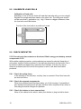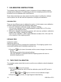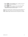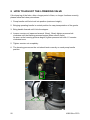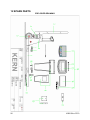
1
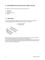
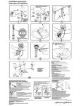
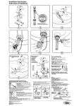
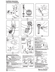
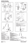
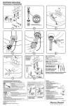
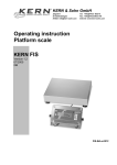
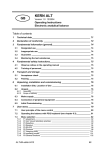
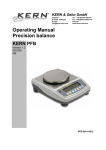
KERN & Sohn GmbH Ziegelei 1 D-72336 Balingen-Frommern E-Mail: [email protected] GB Service Manual Pallet truck scale KERN VHB Version 1.0 05/2007 Tel: 0049-[0]7433- 9933-0 Fax: 0049-[0]7433-9933-149 Internet: www.kern-sohn.com Page 2 CONTENTS 1 2 HOW TO USE THIS SERVICE MANUAL............................................................ 3 THE PRINCIPLE OF THE PALLET TRUCK SCALE ........................................... 4 2.1 MECHANICS................................................................................................ 4 2.2 LOAD CELLS ............................................................................................... 5 2.3 INDICATOR ................................................................................................. 6 2.4 BATTERY..................................................................................................... 6 3 POSSIBLE PROBLEMS...................................................................................... 7 4 DESCRIPTION OF PROBLEM AND WHERE TO LOOK FOR CAUSES............ 8 5 EXPLANATION OF POSSIBLE CAUSES AND HOW TO FIX THEM ................. 9 5.1 CHECK BATTERY ....................................................................................... 9 5.2 CHECK MECHANISM.................................................................................. 9 5.3 CHECK LOAD CELLS................................................................................ 10 5.4 CHECK CABLING AND LOAD CELL BOARD ........................................... 11 5.5 CALIBRATE LOAD CELLS ........................................................................ 12 5.6 CHECK INDICATOR .................................................................................. 12 6 PARAMETER SETTINGS ................................................................................. 14 7 CALIBRATION INSTRUCTIONS....................................................................... 18 7.1 TWO POINT CALIBRATION ...................................................................... 18 7.2 MULTI-POINT CALIBRATION ................................................................... 20 8 HOW TO ADJUST THE LOWERING VALVE.................................................... 22 9 ERROR MESSAGES ........................................................................................ 23 10 WIRING ......................................................................................................... 24 11 DIMENSIONS OF PALLET TRUCK SCALE.................................................. 25 12 SPARE PARTS.............................................................................................. 26 2 VHB-SH-e-0710 1 HOW TO USE THIS SERVICE MANUAL This service manual helps you to solve technical problems with your mobile weighing system. In addition there is a calibration and parameter instruction. Chapter 2 Explains the principle behind electronic weighing systems. Chapter 3 Lists the most frequently occurring problems (A, B, C, D etc.). If your problem is listed in this overview, remember the character and go to Chapter 4. Chapter 4 Connects the problem to possible causes (1, 2, 3, 4 etc.). The most encountered cause is marked with a “Æ”. Remember the number(s) of the cause you should check and go to Chapter 5. Chapter 5 Explains the possible causes in more detail and describes possible solutions. Chapter 6 Explains the parameter settings. Chapter 7 Explains the calibration procedure. Chapter 8 Explains how to adjust the lowering valve. !!! IMPORTANT !!! Do not weld on the system with the load cells mounted. If the welding current passes through the load cell, they will be destroyed. Do not touch the contacts on the electronic boards. Static electricity will destroy components. VHB-SH-e-0710 3 2 THE PRINCIPLE OF THE PALLET TRUCK SCALE The pallet truck scale consists of the following components: 1. 2. 3. 4. Mechanics Load cells Indicator (module) Battery 2.1 MECHANICS The mechanical part is the pallet truck chassis with a special fork construction. For the weighing system the pallet truck fork consists of two parts: 1. The basic chassis 2. The upper forks 2 1 Between the lower / basic fork construction and the upper fork, sensors / load cells are mounted that will sense the force placed on the upper fork. It is most important that all forces pass through the load cells and that no parts of the basic fork, pushrod or load wheel holder of the pallet truck have mechanical contact with the upper fork (weighing part). 4 VHB-SH-e-0710 2.2 LOAD CELLS One of the two most important components of weighing pallet truck are the load cells. A load cell is a rectangular steel component, built in the special pallet truck chassis, in the lower part of the fork. The load cell has a deformation 0.07mm under a load of 1000 kg. This deformation depends on the weight of the load. In the load cell, electrical resistor, called strain gauges, are glued to the load cell body. Strain gauge The electrical resistance of the strain gauges in the load cells changes linearly with the deformation of the load cell. The load cell is connected with four wires to the indicator. Two wires, black and red, supply an input voltage to the load cell. This voltage to the load cells is called excitation. The output voltage of the load cell, called “signal”, green and white wires, depends on the strain gauge resistance change. With a maximum load on the load cells (example: 4 x 1000 kg), the signal voltage (caused by the change in resistance) is approximately 0.01 Volt. The signal voltage at 100 kg is only 0.0002 Volt. The signal change level with 1 kg weight change is only 0.000002 Volt. When working with such small electrical signals, the cabling has to be 100%. Therefore, the signal is transmitted from the load cells to the indicator via a special cable. All connections have to be soldered and humidity or corrosion of contacts will cause instability in the reading. VHB-SH-e-0710 5 2.3 INDICATOR The indicator operates like an ohm/voltmeter. The change in resistance is measured, translated and displayed as a weight. The indicator is a multitude more accurate then a multimeter but in a very limited voltage range. It measures micro voltages at extreme high accuracies, independent from temperature changes and distortion of radio frequencies. The indicators have a power supply of 6 Volt. The power consumption of the indictor is below 20mA. Because of the extremely small signal levels the board is very sensitive to humidity and contact with chemical substances that will influence the solder contacts. 2.4 BATTERY The power supply takes place through 4x 1.5V type AA batteries. 6 VHB-SH-e-0710 3 POSSIBLE PROBLEMS The most frequently occurring causes of malfunctioning of the weighing systems are: • • • • • • Supply: Worn out battery, fuse, or power supply Bad or broken contacts Jammed or worn out cabling Loose screws or bolts Mechanical problems: the upper part of the fork has contact with the chassis or lifting mechanics of the pallet truck due to deformation, wear or accumulated dirt. Moisture in the electronics or load cells These problems cause 99% of all possible failures and will result in the following problem descriptions: A. Nothing works. The display is dead, even when pressing the keys. B. The indicator is unstable; the weight readout goes up and down. C. Different weights are displayed for the same load when weighed several times. D. The weighing system is accurate with lower weights but inaccurate with higher weights. E. The weighing system is inaccurate, however, the inaccuracy is linear, meaning the error is always the same percentage of the weighed load. F. Without a load, a positive or negative weight (Help 2 or 3) is displayed and it is not possible to reset the display to 0kg. The scale reacts normally when a load is placed on the scale. G. An error message indicates over- or underload, with or without load on the scale. H. The display does not react to loads being placed on or removed from the scale. I. Keys do not work. J. Segments fail on display. For error messages displayed on the indicator, please refer to chapter 9. VHB-SH-e-0710 7 4 DESCRIPTION OF PROBLEM AND WHERE TO LOOK FOR CAUSES A. 1 6 J Nothing works. The display is dead, even when pressing the keys. Check battery and charger. Check the indicator. Is the safety fuse still good, or is there a bad contact? 2 4 6 3 J The indicator is unstable; the weight readout goes up and down. Check the mechanism of the fork construction. Check the load cell cables and the load cell calibration board. Check the indicator for moisture or loose contacts. (5.6.2) up to (5.6.6) Check the load cells. Are the screws tight? 2 3 J The same load is lifted several times, but different weights are displayed. Check the mechanism of the fork construction. Check the load cells. The weighing parts may not have contact with fixed, non weighing parts. B. C. D. 2 J E. J F. 5 J H. The weighing system is inaccurate, however, the inaccuracy is linear. This means that with a load of 100 kg the inaccuracy is 1 kg, with 500 kg it is 5 kg, and with a load of 1000 kg the inaccuracy is 10 kg. See calibration procedure. Without a load on the forks a negative or positive weight is displayed. It is not possible to reset the display to zero. The system works normally once a weight is placed on the unit. See calibration procedure. The zero setting has a restricted capacity. Calibrating the system will bring the zero setting to within the restrictions. 6 4 3 The display does not react to loads being placed on the scale. Check the indicator. Only 5.6.1 and 5.6.4. Check the cabling. Check the load cells. 6 Keys do not work. Check the indicator. 6 Segments fail on display. Check the indicator. I. J. 8 The weighing system is accurate with small weights, however, it is inaccurate with heavy weights. Check the mechanism of the fork construction. Because of the bending of the loading part of the system, the weighing part has contact with the rigid part of the system. VHB-SH-e-0710 5 EXPLANATION OF POSSIBLE CAUSES AND HOW TO FIX THEM 5.1 CHECK BATTERY • Check the battery Empty batteries can be replaced with 4x 1.5V new AA batteries. See operating manual. 5.2 CHECK MECHANISM 5.2.1 Check whether weighing is obstructed mechanically. Weigh yourself while standing on the extreme corners of the system. Your weight must be identical on all corners. The difference between the weights maybe up to one graduation. If this is the case, it may be concluded that all load cells are working and the mechanics are fine with small loads. After finishing this test, load the weighing system with a normal or heavy load. Using the tare key, the display is reset to zero. Now, with this weight on the scale, load the corners of the weighing system by placing your own weight on top or side of the weight that is on the scale. Each corner should give an identical read-out plus or minus 1 or 2 kg. If the read-outs are not identical and show a difference larger than 2 graduations, see 5.2.2. 5.2.2 Try to determine where there is interference between weighing and non weighing components. It may be necessary to dismantle the system to see where the interference occurs. Often there are traces on the paint that indicate the most likely place. If there is doubt, assemble the weighing system with paper placed between the weighing and non weighing parts. After loading the system to its full capacity and maybe by moving (shacking) the load side ways, traces on the paper will show where the friction might be. Determine what can be done mechanically in order to end this friction. e.g. align the load cells and the upper fork shoes, allow less moving space for the lifting mechanics in the forks like the push rod and the load wheel holder. It might be necessary to align the rods of the load wheels to prevent them from touching the load cells. It can be that with an unloaded truck it is not possible to see that friction does occur. Therefore see if the rods can touch the load cells by pushing them towards the load cells. Clean the inside of the forks. 5.2.3 Are the bolts tightened correctly? The load cells are mounted with bolts. These must be tightened correctly. Check if all bolts are tightened firmly. 5.2.4 Are the fork shoes mounted freely? (Always check this!) Underneath the pallet truck you can see whether the fork shoes are mounted correctly and do not interfere with the frame (basis of the forks) at the sides. Especially welding of the load wheel axel fixture can interfere. Sometimes pieces of wood or stone can cause friction between weighing and nonweighing parts. VHB-SH-e-0710 9 5.3 CHECK LOAD CELLS 5.3.1 When the weighing system is inaccurate, check whether all load cells give the same weight Using your own weight, this is very easy to check. Weigh yourself while standing on the extreme corners of the system. Your weight must be identical in all corners. It may vary one graduation. When the load cells get older, or when one of them has been replaced, the difference may become somewhat larger. When a large difference occurs, continue from 5.3.2. 5.3.2 Check whether the problem lies with the load cells or with the mechanism Dismantle the forks shoe (or the upper part of the fork). Place bolts in the assembly holes of the load cells. Balance a test weight of approx. 1% of their capacity on each load cell (on the bolts) and check whether each load cell gives the same weight. The maximum difference may only be 1 graduation. When the difference is larger see 5.5. If there is no difference, see 5.2. 5.3.3 If a high weight is shown, without a load, and it is not possible to calibrate to 0kg, check if the load cells are working correctly. Try to recalibrate the system (see 5). To check whether the problem is caused by the indicator, it is most simple to replace the indicator and perform a simple calibration. If this does not solve the problem see 5.3.4 and 5.3.5. 5.3.4 When the indicator shows an error message or is unstable Turn off the indicator and measure with an ohm/voltmeter whether the resistance between all load cell wires and the pallet truck chassis is infinite. No resistance value at all is allowed between the black, white and green load cell wires to the chassis. The resistance between disconnected load cell excitation wires; black and red, should be: +/- 350 Ohm if one load cell is checked +/- 87 Ohm if all 4 load cells are checked when connected parallel. These values should also be measured between the load cell signal wires; white and green. With the indicator turned on, between the load cell excitation wires (black and red) the following values should be measured: • Standard system and without printer: 3.3 V DC. • Legal for trade system (class III) and / or with a printer: 2.5V AC. Because of a block voltage, depending on the voltmeter, a voltage between 2.2 or 2.5 will be measured. If not, the indicator has a problem. With the indicator turned on, with no load on the forks, between the load cell signal wires, green and white, the following values should be measures: • Standard system and without printer: 0.000 to 0.002 V DC. (V AC for printer and /or approved systems) 10 VHB-SH-e-0710 If the signal level is higher or negative, there is a problem with the load cells. If the signal is only slightly higher, it may be that it works anyway but may be temporary. If a problem is found, the last test can be repeated with the individual load cells connected to see if one or more and which load cell(s) have the problem. 5.3.5 Check each individual load cell The load cells are connected to the indicator with the load cell cables. The cables are connected to each other by a coupling cover. By removing this, the load cells can be tested individually. 1.Possibility: Measure the power supply. The power between +power supply (mostly red) and +signal (mostly green) and the power between –power supply (mostly black) and –signal (mostly white) should be equal to 2Ω. The power between the cables and the load cells should be infinite (∞). 2.Possibility: To check whether the problem is caused by a single load cell: connect the load cells to the indicator separately from each other (use the indicator as voltmeter) and compare the data on the indicator per load cell. The values should be almost identical. The weight shown is dependant on the calibration. Is a value instable or varies considerably from the other values, then this load cell should be replaced. Before replacing the load cell, the batteries should be replaced. 5.3.6 If the display is unstable, check which load cell is defective When the cables of the load cells are all disconnected, it is possible to test each load cell separately. Connect each load cell separately to the indicator in order to see if and which load cell is unstable. If the indicator reacts unstable at each load cell, check again if the indicator is not the cause for this problem, see 5.6. 5.4 CHECK CABLING AND LOAD CELL BOARD 5.4.1 Check for damaged cables Touch the load cell cable or move it back and forth, especially where the cable is connected. The indicator should not react to this. If the indicator reacts, then the cable is damaged internally or there is moisture in the cable and the cable needs to be replaced. The load cell board should also be checked. If the load cell board of the connected cables is bent, without touching the contacts points, and the indicator reacts, then there is a bad connection. If the load cell board is oxidized then warming the solder points with a soldering unit can offer a solution. The cable can be replaced (temporarily) by another cable to see if this will solve the problem. VHB-SH-e-0710 11 5.5 CALIBRATE LOAD CELLS Calibration of load cells Standing on one of the two forks will load the load cells with your own weight. Register the weight and then stand on the other fork. The difference should not be more than 1 graduation (eg. 1 kg). If there is a bigger difference, then the load cells could be broken. Position of the load cells in a pallet truck scale 5.6 CHECK INDICATOR !!!!!!! Do not touch the contacts on the board. Static energy can destroy several components !!!!!!!! With mobile weighing systems, most problems are caused by shocks. Keep this in mind when trying to locate a problem in the indicator housing or on the board. Don’t be afraid to check and apply heavy shocks to the indicator. It is the only way to discover problems that occur when the system is used. It will also show latent problems. 5.6.1 Check the safety fuses In the housing of the indicator, a safety fuse is mounted. Check this fuse with an ohm/volt meter. 5.6.2 Check the separate components When the indicator board has been taken out of the housing, it is possible to see whether everything looks all right, whether other components are loose or if bending the board changes the problem. 5.6.3 Check for broken or loose connections None of the cables to the switch, safety fuse holder or plug should be loose. 12 VHB-SH-e-0710 5.6.4 If the display is unstable or does not react to weights, check whether the indicator causes the problem Disconnect the indicator from the load cells (also if the display will give an error message). Connect each load cell individually. If the indicator remains unstable or does not react to the different load cells, most likely the indicator module is faulty. 5.6.5 If the display is unstable, check for moisture Look for condensation or water drops on the plugs. Look closely at the circuit board, when dismantling the upper plate and pulling out the plug from the indicator module. Dry it with warm air. If the board is oxidised, it can help to heat solder points carefully with a solder iron around the analogue circuit. 5.6.6 When can you be certain that the indicator board is faulty? The display is faulty when: - nothing changes when load cells are being disconnected - nothing lights up with +6 V DC at the right contacts, and functioning keyboard - the indicator remains unstable, even with only one load cell connected - the display reacts when the indicator module is subjected to shocks 5.6.7 Check the touch panel. Look at the flat cable. The silver conducting layer is very thin. Wear in a small area can cause the touch panel to dysfunction. The connector on the flat cable is very sensitive to humidity. Check for this. If humid, heat this component for a longer period of time. 5.6.8 Check LCD display on the indicator By bending the board slightly while functioning, in different directions and diagonally, broken display contacts can be located. VHB-SH-e-0710 13 6 PARAMETER SETTINGS ¾ Switch off the indicator. ¾ To activate the parameter menu, press the ❏ The indicator shows: “P 01“. ON/ OFF UNIT key for 23 seconds. TARE ¾ Press the key. ❏ The indicator shows the current value of parameter P 01. ¾ Use keys PRETARE and TOTAL to change the current value. TARE ¾ Confirm with . ❏ The indicator shows: “P 02“. Parameter P 02 can now be changed in the same way as P 01. TOTAL key it is possible to scroll through the parameters, until the ❏ With the desired parameter is reached. ON/ OFF UNIT ❏ When the key is pressed shortly while a parameter number is shown in the display, the parameter indication will automatically jump back to P 01. TARE key for 3 ¾ When all desired parameters have been changed, press the seconds to leave the parameter menu and to return to the weighing mode. Listed below are all available parameters. - Settings for specific options are indicated with an asterisk (*). Contact the producer to check whether you have the correct hardware for this option. If the hardware is not suitable for a certain function, it will not be possible to activate or change that function. - The factory settings for your board can be found in the table. Contact the producer to check which hardware version you have. 14 P 01: Option RF*(not available): RF-function identification number, to ensure that the correct devices are in communication. Available identification numbers: 0 - 7. Option RCS*(not available): delay time for the peak hold function, 0 - 9 seconds. Setting = 0 P 02: Sets smallest graduation of multi-range. 0.1 = 0.1 kg 0.2 = 0.2 kg 0.5 = 0.5 kg 1 = 1 kg 2 = 2 kg 5 = 5 kg 10 = 10 kg 20 = 20 kg 50 = 50 kg Setting = 1 VHB-SH-e-0710 P 03: Sets largest graduation of multi-range. 0.1 = 0.1 kg 0.2 = 0.2 kg 0.5 = 0.5 kg 1 = 1 kg 2 = 2 kg 5 = 5 kg 10 = 10 kg 20 = 20 kg 50 = 50 kg Setting = 1 Attention: P 02 must always have a lower value than P 03. If, by mistake, a higher value is set, then the indicator automatically sets the same value for both parameters, and the multi-interval function is not used. P 04: Sets the number of graduations per multi-range, per 100 graduations. Available values 0000 – 9900, for the legal for trade version 500 – 3000*. Attention: when P 02 and P 03 have equal values, and the multi-range is therefore inactive, the value for P 04 is represented as ‘’----“. Setting = - - - - - P 05: Sets the weighing capacity (full scale), adjustable per 100 kg. Available values 00000 – 99900. Setting = 02000 P 06: Sets the motion detection, in graduations per second. When the internal value varies per second more than the number of set graduations, the load stability pointer will not light up in the display. 0 = 0.5 graduation (standard for option* approved systems) 1 = 1 graduation 2 = 2 graduations 3 = 4 graduations Setting = 1 P 07: Not defined (- - - - -) P 08: Sets time for AUTO-OFF function in minutes. Available values 1- 99 (0 = inactive). Setting = 3 P 09: Sets number of wires per load cell cable. 4 = 4 wires 6 = 6 wires (prepared for approval) Setting = 4 VHB-SH-e-0710 15 P 10: Option: turns off automatic zero correction*. For certain dosage applications. 0 = off 1 = on Setting = 1 P 11: Not defined (- - - - -) P 12: Starting unit (also calibration unit) 0 = kg 1 = lb 2 = kg/lb 3 = lb/kg Setting = 0 P 13-16: Not defined (- - - - -) P 17: Option: peak hold function* (not available) 0 = standard function 1 = peak hold function Setting = 0 P 18 -19: Not defined (- - - - -) 16 P 20: Option: printer or printer output*. Sets baud rate. Available values: 600/1200/2400/4800/9600. Setting = 9600 P 21: Option: printer or printer output*. Sets the number of data bits. Available values: 7/8. Setting = 8 P 22: Option: printer or printer output*. Sets parity. E = even - = none 0 = odd Setting = - P 23: Option: printer or printer output*. Sets number of stop bits. Available values: 1/2. Setting = 1 P 24: Not defined (- - - - -) P 25: Option: printer or printer output*. Sets RS232-board function. 0 = Standard 1 = Standard with printer 2-7 = not used Setting = 0 VHB-SH-e-0710 P 26: Option: printer or printer output*. Sets number of line feeds after total print. Available values: 0-7. Setting = 5 P 27– 89: Not defined (- - - - -) P 90: Reset to factory settings. When after selection of parameter P 90 the TARE key is pressed, all parameter settings are automatically reset to the factory settings. NB: Be aware that the factory settings are incorrect for some systems. Make sure that you have a copy of the correct parameters before resetting the system. !!!Do not use this setting, the unit will need to be recalibrated!!! P 91: Not defined (- - - - -) P 92: Sets the low battery auto shut off function. When activated, the indicator will switch off automatically 2 minutes after the “lo-ba” indication comes on. 0 = inactive 1 = active Setting = 1 P 93: Main function keys 2 and 3 0 = all functions are activated 1 = PT deactivated 2 = ∑ deactivated 3 = PT and ∑ deactivated incl. the net and stability pointers Setting = 0 P 94–98: Not defined (- - - - -) P 99: Shows software version of the indicator (e.g. 7 51). VHB-SH-e-0710 17 7 CALIBRATION INSTRUCTIONS The indicator offers the possibility to enter a maximum of three calibration points (multiple point calibration). The advantage is that even weighing systems with bad hysteresis can be calibrated within specifications. Since these instructions are often used in the field, where it is difficult to calibrate various points, we will start with the explanation of single point calibration. POSSIBILITIES There are two different ways to calibrate the system. In both cases a zero calibration should be performed before the calibration takes place. 1. Two point calibration (calibration weight 1000kg to 1500kg). This is a zero calibration and 1 weight calibration at about 50% to 75% of the capacity of the weighing system. 2. Multi-point calibration for weighing systems with accuracy problems (calibration weights about 200kg, 1000kg and 1500kg) This is a zero calibration + three weight calibrations at about 10%, 50% and 75% of the capacity of the weighing system. DEFINING ZERO Unload the system. Switch the system on. Lift the weighing system by pumping the handle twice. The weighing system is not underneath anything and is standing completely free. TARE Push the key for about 9 seconds until the screen changes, then release the key. The weighing system shows several settings. The zero calibration is completed and the weighing system will return to standard weighing mode. 7.1 TWO POINT CALIBRATION The weighing system should be turned on and the zero calibration should already be completed. PRETARE key for 20 seconds. Press the The indicator shows the value of the first calibration point, the NET pointer is flashing. Use the PRETARE Press the 18 , TARE TOTAL and TARE keys to enter the correct calibration weight. key shortly, the right segment starts flashing. VHB-SH-e-0710 Use the to “2”). PRETARE Press the Use the TARE PRETARE Press the Use the or key to set the first calibration weight (eg. for 1472 kg, set key shortly to confirm, now the second segment is flashing. or TARE PRETARE TOTAL TOTAL key to set this to “7”. key shortly to confirm, now the third segment is flashing. or TOTAL key to set this to “4”. The thousands segment should be set, if necessary, to “1”, in the same way as the previous segments. Confirm all other segments with TARE until the NET pointer is flashing. Lift the calibration weight (in the above mentioned example 1472kg). TARE Press the key for about 4 seconds to confirm. The display counts down to “AF00”. The first calibration value is displayed. TOTAL key, the ~ pointer is flashing, the middle calibration value should Press the be set to “00000” for a two point calibration. TARE Press the Use the PRETARE , key shortly, the right segment starts flashing. TOTAL and TARE keys to set the middle calibration weight (00000kg) as described above. Confirm all segments with flashing. TARE until the ~ pointer is TARE Press the key for about 4 seconds to confirm. The display counts down to “AF00”. The middle calibration value is displayed. TOTAL Press the key, the NET + ~ pointers are flashing, the last calibration value should be set to “00000” for a two point calibration. TARE Press the Use the PRETARE , key shortly, the right segment starts flashing. TOTAL and TARE keys to set the middle calibration weight (00000kg) as described above. Confirm all segments with are flashing. TARE until the NET + ~ pointers TARE Press the key for about 4 seconds to confirm. The display counts down to “AF00”. The last calibration value is displayed. TOTAL Press the key to leave the calibration mode, the weigh systems displays eg. AP 11 (internal value). TARE Press the key for about 4 seconds, the system returns to standard weighing mode, shows the actual weight on the forks, the calibration is completed and the calibration load can be lowered. VHB-SH-e-0710 19 7.2 MULTI-POINT CALIBRATION The weighing system should be turned on and the zero calibration should already be completed. PRETARE Press the key for 20 seconds. The indicator shows the value of the first calibration point, the NET pointer is flashing. Use the PRETARE Press the Use the “0”). Use the TARE TARE keys to enter the correct calibration weight. TOTAL key to set the first calibration weight (eg. for 250 kg, set to key shortly to confirm, now the second segment is flashing. or TARE PRETARE and key shortly, the right segment starts flashing. or PRETARE Press the Use the TARE PRETARE Press the TOTAL , TOTAL key to set this to “5”. key shortly to confirm, now the third segment is flashing. or TOTAL key to set this to “2”. The thousands segment should be set, if necessary, to “0”, in the same way as the previous segments. Confirm all other segments with TARE until the NET pointer is flashing. Lift the calibration weight (in the above mentioned example 250kg). TARE Press the key for about 4 seconds to confirm. The display counts down to “AF00”. The first calibration value is displayed. The first calibration weight can be lowered. TOTAL key, the ~ pointer is flashing, the middle calibration value can Press the now be entered. Press the Use the TARE PRETARE , key shortly, the right segment starts flashing. TOTAL and TARE keys to set the middle calibration weight (eg. TARE 1250kg) as described above. Confirm all segments with until the ~ pointer is flashing. Lift the calibration weight (in the above mentioned example 1250kg). TARE Press the key for about 4 seconds to confirm. The display counts down to “AF00”. The middle calibration value is displayed. The middle calibration weight can be lowered. TOTAL Press the key, the NET + ~ pointers are flashing, the last calibration value can now be entered. Press the Use the TARE PRETARE , key shortly, the right segment starts flashing. TOTAL and TARE keys to set the last calibration weight (eg. 1875kg) TARE as described above. Confirm all segments with until the NET + ~ pointers are flashing. Lift the calibration weight (in the above mentioned example 1875kg). 20 VHB-SH-e-0710 TARE Press the key for about 4 seconds to confirm. The display counts down to “AF00”. The last calibration value is displayed. TOTAL Press the key to leave the calibration mode, the weigh systems displays eg. AP 11 (internal value). TARE Press the key for about 4 seconds, the system returns to standard weighing mode, shows the actual weight on the forks, the calibration is completed and the calibration load can be lowered. Attention: When a weighing system is calibrated using the multi-point calibration, the smallest weight should be used first, then the middle weight and finally the largest weight. If only 1 calibration weight is used, then values 2 and 3 must be set to “00000”. VHB-SH-e-0710 21 8 HOW TO ADJUST THE LOWERING VALVE If the lowering of the forks, after a longer period of time, no longer functions correctly, please follow the below procedures: 1. Pump handle until forks lock into position (maximum height). 2. Bringing operating handle in neutral position for easy transportation of the goods. 3. Bring handle forward until it hits the stopper. 4. Loosen counter nut (open-end wrench 10mm). Slowly tighten pressure bolt clockwise until the lowering process begins (Allen wrench 3mm). As soon as the lowering process begins, tighten pressure bolt with 1.5 counterclockwise turns. 5. Tighten counter nut completely. 6. The lowering process on the unit should work correctly on each pump handle position pressure bolt 22 counter nut VHB-SH-e-0710 9 ERROR MESSAGES HELP 1 Weighing system overloaded HELP 2 Taring impossible due to negative gross weight HELP 3 Negative signal of load cells to A-D converter / slant HELP 4 key again in order to Entered tare weight is too high. Press the cancel the HELP display and enter a new, reduced tare weight. HELP 7 The signal of the load cells on the A-D converter is too high. LO-BA The battery status is too low; replace batteries. PRETARE VHB-SH-e-0710 23 10 WIRING 24 VHB-SH-e-0710 11 DIMENSIONS OF PALLET TRUCK SCALE 103° B E 103° 65 F D C A A = 1150 mm B = 180 mm C = 85 mm D = 205 mm E = 555 mm F = 725 mm Production tolerance ±2 mm VHB-SH-e-0710 25 12 SPARE PARTS EXPLODED DRAWING 26 VHB-SH-e-0710 SPARE PARTS LIST KERN VHB 2T1 No. Part Number Description 1 RVHB-1001 Load cell 4 2 RVHB-9001 Mounting plate for load cell (3 mm) 4 3 RVHB-8001 Handle / drawbar 1 4 RVHB-8002 Pump 1 5 RVHB-8003 Steering wheel (rubber) 2 6 RVHB-8004 Chassis of the mobile weighing system 1 7 RVHB-6001 Upper forks / fork shoes 1 8 RVHB-8005 Load roller, tandem PU (kit) 2 9 RVHB-8006 Erection column of indicator module 1 10 RVHB-8007 Cover plate of hole for printer (1+2 ) 1 11 RVHB-4001 Overlay 1 12 RVHB-8008 Battery cover 1 13 RVHB-8009 Plastic housing 1 14 RVHB-2001 Indicator (PCB) 1 15 RVHB-2002 Load cell board 1 16 RVHB-2003 Indicator module complete (incl. overlay) 1 17 Local Batteries size AA 1.5V 4 18 RVHB-9002 Screws to fix the load cells 8 19 RVHB-9003 Screw + nut to fix the fork shoes 4 - RVHB-9004 Gasket set of hydraulics 1 VHB-SH-e-0710 Quantity 27