1
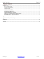
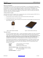
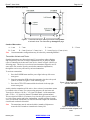
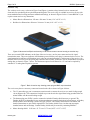
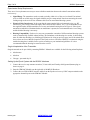
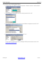
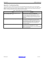
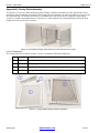
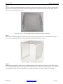
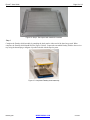
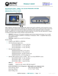
Doc83 v5 ™ Epoch User Manual Epoch™ Wireless EEG System For Life Science Research Applications 42 Aero Camino, Goleta, CA 93117 Tel (805) 685-0066, Fax (805) 685-0067 WWW.BIOPAC.COM Epoch™ User Guide Page 2 of 13 TABLE OF CONTENTS System Overview .............................................................................................................................................................................3 How to Use This Manual..........................................................................................................................................................3 The Epoch Wireless System.....................................................................................................................................................3 Transmitter Implant..................................................................................................................................................................3 Transmitter Electrode Spacing .................................................................................................................................................4 Transmitter Activator and Tester..............................................................................................................................................4 Receiver Tray ...........................................................................................................................................................................5 Experimental Setup Requirements ...........................................................................................................................................7 Surgical Implantation of the Transmitter..................................................................................................................................7 Setting Up the Epoch System with the BIOPAC Hardware.....................................................................................................7 Epoch Module Setup in AcqKnowledge Software ...................................................................................................................8 Appendix A: Troubleshooting Guide ............................................................................................................................................9 Appendix B: Faraday Shield Assembly.......................................................................................................................................10 Intended Use ..................................................................................................................................................................................13 Warranty .......................................................................................................................................................................................13 R01839_04b WWW.BIOPAC.COM 5/21/2015 Page 3 of 13 BIOPAC Systems, Inc. System Overview How to Use This Manual This manual provides an overview of the Epoch wireless dual-channel in vivo recording system for small animal research and how to set up the system in AcqKnowledge software. The specifications and diagrams that are provided in this manual are to assist users in understanding the capabilities of the Epoch system. This document is not intended as a service manual. Only authorized BIOPAC employees and representatives are qualified to repair any component of the system. All rights of the warranty for said component are voided if any other party modifies any component without the written consent of BIOPAC. The Epoch Wireless System The Epoch wireless system is comprised of three components that can be used for the acquisition of EEG, ECoG, or LFP signals from naturally or freely-behaving, small animals: The dual-channel wireless transmitter, which is affixed to the head of the animal, Figure 1. The dual-channel wireless receiver base, Figure 2. The Faraday shield used to reduce the amount of noise interference from the ambient environment if present, shown in Figure 9. (Page 6) Figure 1. Epoch wireless transmitter Figure 2. Epoch wireless receiver tray Transmitter Implant The wireless transmitter implant, Figure 1, contains a small amplifier, transmitter, and a battery encapsulated in medical-grade epoxy. Each electrode is made of Platinum-Iridium (Pt90/Ir10) material insulated with Teflon, with a 0.127 mm diameter (0.005 in.). Two of these leads are for acquiring independent biopotentials with the third lead being the common reference electrode. Spacing for these details is detailed on the following page. The transmitter is shipped activated, and is available with a two-month battery life (2 mo) commonly used for mouse studies, or a six-month battery life (6 mo) commonly used for rat studies. The output gain of the transmitter is set at 2000x during production (±1.0 mV range), but can be set to the follow gains depending on your needs: 800x (Status-Epilepticus in adult animals) or 2000x (EEG, ECoG, LFP). A transmitter activator may be used to activate transmitters on-site. The technical details of the transmitters are as follows: Footprint: 7 mm x 9 mm (2m), 7 mm x 12 mm (6m) Weight: 2.3 g (2 m), 4.0 g (6 m) Volume: 0.756 cm3 (2 m), 1.344 cm3 (6 m) System Gain Options: 800x -- (±2.5 mV range, 2.5 mV in = 2 V out) 2000x -- (±1.0 mV range, 1.0 mV in = 2 V out) Bandwidth: 0.1 – 100 Hz per channel Input Referred Noise: < 7.0 μV rms R01839_04b WWW.BIOPAC.COM 5/21/2015 Epoch™ User Guide Page 4 of 13 Transmitter Electrode Spacing Figure 3. Transmitter electrode spacing schematic looking down at animal’s head. The electrodes go through the page. Standard Dimensions: A – 1 mm C – 7 mm E – 5 mm B – 5 mm D – 2 mm (2 mo) or 3.5 mm (6 mo) F – 9 mm (2 mo) or 12 mm (6 mo) Note G – 3.5 mm Custom transmitter configurations may be ordered by contacting BIOPAC. Transmitter Activator and Tester Standard transmitters are shipped activated. For researchers whose shipping and customs may take time, or whose implantations may be delayed, Ripple offers a Transmitter Activator and Tester device, shown in Figure 4 below (see following page). This device is used to activate transmitters shipped in an offstate, and to test an entire Epoch system before transmitter implantation, through the receiver tray and a newly activated transmitter. To activate a transmitter: 1. Press the POWER button until the power light in the top left corner turns green. 2. Insert the transmitter PCB so that the transmitter sits above the epoch symbol, as shown in Figure 5 on the following page. 3. Press the ACTIVATE button until the check mark in the top right corner turns green. Figure 4. Dual channel transmitter activator and tester At this point the transmitter will be active. Once activated, a transmitter cannot be returned to the off state. For system testing purposes, the Activator and Tester device delivers a 54-Hz, ± 1-V signal via channel 1 of the transmitter, and a 27-Hz, ± 1-V signal via channel 2 (standard 2000x gain transmitter). This test signal will last for 2.5 minutes every time the device power is turned on. After system testing and before implantation, carefully snip the electrode wires, free from the circuit board, to a desired electrode length. The transmitter circuit board can then be discarded. Note The transmitter must be activated within 6 months of shipment to ensure the full 2-month or 6-month active battery-life. R01839_04b WWW.BIOPAC.COM Figure 5. Activation of dual channel transmitter shipped in off state 5/21/2015 Page 5 of 13 BIOPAC Systems, Inc. Receiver Tray The wireless receiver tray, as shown in Figure 2 and Figure 6, contains a large internal receiver antenna and electronics for reproducing the acquired biopotential signals. The receiver tray is available in two sizes for use with most standard mouse housings and most standard rat housings, as shown in Figure 6 below. Contact BIOPAC if you require custom receiver tray dimensions. Mouse Receiver Dimensions: 345 mm x 210 mm x 21 mm (13.6" x 8.25" x 1.0") Rat Receiver Dimensions: 429 mm x 216 mm x 21 mm (16.9" x 8.5" x 1.0") Figure 6. Mouse and rat Epoch receiver trays. Inset shows common mouse housing on receiver tray. There are two small LED indicators on the front of the receiver tray, one for power status and one for signal transmission status. The power indicator will illuminate green when the power plug is connected to the receiver. The signal transmission indicator will illuminate green when an activated transmitter is within range of the receiver. On the back of the receiver tray are the power plug connector and two BNC connectors, one for each channel of acquired analog data, as shown in Figure 7 below. The maximum output of each Channel is ±4 V and can be acquired by standard ±5 V analog data acquisition systems. Figure 7. Back of receiver tray showing power plug and BNC output terminals The receiver tray has two accessory connectors located on the side as shown in Figure 8 below. The 3.5 mm audio-type port is an antenna extension used to connect the receiver to a metal feeding trough via an alligator clip. This connection is helpful to prevent the wireless signal from being grounded when an animal climbs onto the metal feeding trough. The banana-plug port (GND) is used to connect the included Faraday shield accessory to ground. The Faraday shield is recommended in any environment that may contain electrical noise interference. A Faraday shield around a mouse housing is shown in Figure 9 below. The Faraday shield must be assembled, and detailed instructions are provided in Appendix B. The Faraday shield is two sizes that can encompass standard mouse and rat housings. Custom Faraday shields may be created by contacting BIOPAC. Mouse housing shield: 36.20 cm x 31.75 cm x 31.75 cm (14.25" x 12.5" x 12.5") R01839_04b WWW.BIOPAC.COM 5/21/2015 Epoch™ User Guide Rat housing shield: Page 6 of 13 51.44 cm x 36.83 cm x 36.83 cm (20.25" x 14.5" x 14.5") Figure 8. Antenna extension and Faraday shield connections R01839_04b WWW.BIOPAC.COM Figure 9. Epoch mouse wireless system with Faraday shield 5/21/2015 Page 7 of 13 BIOPAC Systems, Inc. Experimental Setup Requirements There are a few requirements necessary to ensure reliable transmission between the animal’s transmitter and the receiver tray: Signal Range. The transmitter needs to remain vertically within 6 in. of the receiver board. If an animal were to climb out of this range, the signal reliability may be compromised. Note that connecting the metal feeding trough to the receiver base eliminates this issue for most animal housing systems. Electrical Noise Interference. In the event that the room contains high environmental noise (e.g., RF interference, power strips, fluorescent lights, other 50/60 Hz noise sources, etc.), it is recommended to use the supplied Faraday shield around the receiver tray and animal housing shown in Figure 9. If the signal transmission indicator is illuminated when no transmitter is present, the environmental noise is too strong and the shielded housing is necessary. Housing Compatibility. Each receiver tray can accommodate a number of different animal housing systems such as commercially-available rodent housing. The limitations on the housing size are that 1) the housing must fit within the shielding (see shielding specifications for sizing on previous page) and 2) the animal must have at least one foot within the footprint of the Epoch receiver at all times. BIOPAC recommends using the smallest housing that is suitable for the species according to your institutional guidelines. It is also recommended that the housing be centered on the receiver. Surgical Implantation of the Transmitter Surgical manuals can be provided by contacting BIOPAC. Manuals are available for the following animal implants: Adult mouse Adult rat Rat pup - post-natal day 18. Setting Up the Epoch System with the BIOPAC Hardware 1. Connect the receiver tray antenna extension (3.5 mm cable) and Faraday shield ground (banana plug) as shown on page 6. 2. Snap the UIM100C Module onto the right side of the MP150 Hardware. 3. Connect the two CBL102 BNC interface cables from the Epoch receiver tray’s BNC output terminals to the appropriate channel inputs on the UIM100C Module. R01839_04b WWW.BIOPAC.COM 5/21/2015 Epoch™ User Guide Page 8 of 13 Epoch Module Setup in AcqKnowledge Software 1. In AcqKnowledge, go to “MP150 > Set Up Data Acquisition > Channels” and choose “Add New Module.” 2. Select the UIM100C corresponding to the desired Analog channel and click “Add.” 3. Select the Epoch Transmitter (and desired gain) from the UIM100C Configuration list and click “OK.” 4. Enter a channel label for the new configuration and click “Close.” For more details on AcqKnowledge software, including the EEG Specialized Analysis routines see the AcqKnowledge 4 Software Guide. R01839_04b WWW.BIOPAC.COM 5/21/2015 Page 9 of 13 BIOPAC Systems, Inc. Appendix A: Troubleshooting Guide This appendix provides helpful hints and solutions for troubleshooting the Epoch wireless system. This appendix addresses issues that may not be consistent across all customers. Consistent, replicable problems will be addressed by BIOPAC engineers. This appendix will be updated with problems found by customers and solutions determined by BIOPAC. All solutions have been tested as much as possible by BIOPAC. Table 1. Epoch wireless system troubleshooting solutions: Error Solution The signal status indicator is illuminated even when there is no transmitter in range. This occurs when there is too much electrical interference in the environment. BIOPAC recommends the use of the provided Faraday shield that can be grounded to the Epoch receiver GND port. It can also be helpful to use the Epoch system on racks that can be grounded. Signal appears to be extremely noisy and/or floating. This can occur if the ground electrode on the transmitter is not making a low-impedance connection with the surrounding tissue, or if the electrode becomes encased in glue during implantation fixation. The solution is to recheck the electrode placement and possibly the electrode tip as well. The signal looks noisy directly after implantation. The surgical implant procedure often results in acute trauma that can cause degradation of the signal. BIOPAC recommends waiting 24 hours post-implantation before recording signals. R01839_04b WWW.BIOPAC.COM 5/21/2015 Epoch™ User Guide Page 10 of 13 Appendix B: Faraday Shield Assembly The Epoch in vivo wireless EEG monitoring system includes a Faraday shield that can reduce the amount of noise interference from the ambient environment. This Faraday shield is designed to be placed around the receiver tray and the animal housing. The Faraday shield must be assembled by the end user because it is shipped with the Epoch system in a compact unassembled form to reduce the size of the shipment. The assembled Faraday shield will look similar to those shown in Figure 10 below. Figure 10. Assembled Faraday shield (Rat size on left / Mouse size on right) List of Components The Faraday shield kit, as shown in Figure 11 below, contains the following components: Item: Quantity: Description: 1 20 M4 x 8 mm oval-head screws 2 5 8" long tapped-hole L-brackets 3 3 Long panels – 2 side, 1 top - 14" x 12" for mouse, 20" x 14" for rat (L x W) 4 1 Back panel – 10" x 12" for mouse, 14" x 12" for rat (L x W) Figure 11. Unassembled Faraday shield components R01839_04b WWW.BIOPAC.COM 5/21/2015 Page 11 of 13 BIOPAC Systems, Inc. Step 1 Take one of the long panels and attach two L-brackets to the long sides as shown in Figure 12 below, using the outer tapped hole on one end of the L-bracket and the inner tapped hole on the other end of the L-bracket. Note: either set of holes on the L-bracket may be used. Figure 12. Step 1 – Top assembled using one long panel and two L-brackets Step 2 Using the two remaining long panels, attach one panel to each of the open faces of the L-brackets placed in Step 1 above. At the completion of Step 2, the Faraday shield should look like Figure 13 below. Figure 13. Step 2 – Top and sides assembled Step 3 Attach the three remaining L-brackets to the smaller back panel as shown in Figure 14 below. For the top L-bracket, use one outer tapped hole and one inner tapped hole, similar to Step 1. For the two side L-brackets, be sure to use the outer tapped hole on the side of the L-bracket closest to the top L-bracket, as shown in Figure 14 (next page). R01839_04b WWW.BIOPAC.COM 5/21/2015 Epoch™ User Guide Page 12 of 13 Figure 14. Step 3 - Back panel with attached L-brackets Step 4 Complete the Faraday shield assembly by attaching the back panel to either end of the three long panels. When complete, the Faraday shield should look like Figure 15 below. Connect the assembled Faraday shield to the receiver tray using the banana plug to alligator clip cable included with the Epoch system. Figure 15. Completed Faraday shield assembly R01839_04b WWW.BIOPAC.COM 5/21/2015 Page 13 of 13 BIOPAC Systems, Inc. Intended Use BIOPAC Systems, Inc., instruments, components, and accessories are designed for educational- and researchoriented life science applications and investigations. BIOPAC Systems, Inc. does not condone the use of its instruments for clinical medical applications. Instruments, components, and accessories provided by BIOPAC Systems, Inc., are not intended for the diagnosis, cure, mitigation, treatment, or prevention of disease. Warranty BIOPAC Systems, Inc. warrants to the original end purchaser that the Epoch™ hardware shall be free from material defects in material and workmanship for a period of one (1) year from the original date of purchase (the "Hardware Warranty Period") the software shall be free from material defects or errors for a period of one (1) year from the original date of purchase (the “Software warranty period”). If the product is determined to be materially defective during the Warranty Period, your sole remedy and BIOPAC’s sole and exclusive liability shall be limited to the repair or replacement of this product with a new or refurbished product at BIOPAC’s or its licensed distributor’s option. For purpose of this Limited Hardware Warranty and Liability, "refurbished" means a product that has been returned to its original specifications. Visit WWW.BIOPAC.COM for instructions on how to deliver the product to an authorized service facility. This warranty shall not apply if this product a) is used with products that are not compatible with this product b) is modified, or tampered with c) is damaged by acts of God, misuse, abuse, negligence, accident, wear and tear, unreasonable use, or by other causes unrelated to defective materials or workmanship d) has had the serial number altered, defaced or removed e) has, in the reasonable opinion of BIOPAC or its licensed distributors, been opened, altered, or defaced. This warranty shall also be voidable by BIOPAC or its licensed distributors If (1) BIOPAC reasonably believes that the Epoch™ system has been used in a manner that would violate the terms and conditions of a separate end user license agreement for system software; or (2) the product is used with products not sold or licensed by BIOPAC. You assume all risks and liabilities associated with use of third party products. This warranty is provided to you in lieu of all other express or implied warranties including warranties of merchantability and fitness for a particular purpose for the Epoch™ system, which are disclaimed hereunder. However, if such warranties are required as a matter of law, then they are limited in duration to the warranty period. Our sole and exclusive recourse in the event of any dissatisfaction with or damage arising from the use of the Epoch™ system and BIOPAC's maximum liability shall be limited to repair or replacement of the Epoch™ system. Except as expressly stated above, BIOPAC excludes all liability for any loss of data, loss of profit, or any other loss or damage suffered by you or any third party, whether such damages are direct, indirect, consequential, special, or incidental and however arising under any theory of law, as a result of using your Epoch™ system. Some countries, states or provinces do not allow limitation on how long an implied warranty lasts and some countries, states and provinces do not allow the exclusion or limitations of consequential or incidental damages, so the limitations or exclusions may not apply to you. This warranty gives you specific legal rights, and you may also have other rights which vary from country to country, state to state or province to province. This warranty is in all countries where BIOPAC has an office or a licensed distributor. The warranty offered by BIOPAC Systems, Inc. on your Epoch™ hardware is the same whether or not you register your product. EPOCH™ is a trademark of Ripple LLC. R01839_04b WWW.BIOPAC.COM 5/21/2015