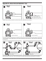
1
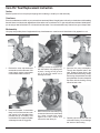
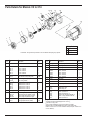
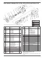
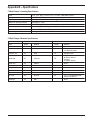
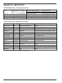
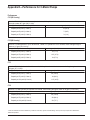
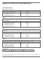
IF101J Installation, Operation & Maintenance Manual Coro-Flo® Pumps C-Model DS-/DL-Model F-Model Warning: (1) Periodic inspection and maintenance of Corken products is essential. (2) Inspection, maintenance and installation of Corken products must be made only by experienced, trained and qualified personnel. (3) Maintenance, use and installation of Corken products must comply with Corken instructions, applicable laws and safety standards (such as NFPA Pamphlet 58 for LP-Gas and ANSI K61.1-1972 for Anhydrous Ammonia). (4) Transfer of toxic, dangerous, flammable or explosive substances using Corken products is at users risk and equipment should be operated only by qualified personnel according to applicable laws and safety standards. Warning Install, use and maintain this equipment according to Corkens instructions and all applicable federal, state, local laws and codes. Periodic inspection and maintenance is essential. Corken One Year Limited Warranty Corken, Inc. warrants that its products will be free from defects in material and workmanship for a period of 12 months following date of purchase from Corken. Corken products which fail within the warranty period due to defects in material or workmanship will be repaired or replaced at Corkens option, when returned, freight prepaid to Corken, Inc., 3805 N.W. 36th Street, Oklahoma City, Oklahoma 73112. Parts subject to wear or abuse, such as mechanical seals, blades, piston rings, packing and other parts showing signs of abuse are not covered by this limited warranty. Also, equipment, parts and accessories not manufactured by Corken but furnished with Corken products are not covered by this limited warranty and purchaser must look to the original manufacturers warranty, if any. This limited warranty is void if the Corken product has been altered or repaired without the consent of Corken. All implied warranties, including any implied warranty of merchantability or fitness for a particular purpose, are expressly negated to the extent permitted by law and shall in no event extend beyond the expressed warranty period. Corken disclaims any liability for consequential damages due to breach of any written or implied warranty on Corken products. Transfer of toxic, dangerous, flammable or explosive substances using Corken products is at the users risk. Such substances should be handled by experienced, trained personnel in compliance with governmental and industrial safety standards. Important notes relating to the European Union (EU) Machinery Directive Pumps delivered without electric motors are not considered as machines in the EU Machinery Directive. These pumps will be delivered with a Declaration of Incorporation. The fabricator of the machinery must assure and declare full compliance with this Directive before the machine in which the pump will be incorporated, or of which it is a part, is put into service. Contacting the Factory Before you contact the factory, note the model number and serial number of your pump. The serial number directs us to a file containing all information on material specifications and test data applying to your specific pump. When ordering parts, the Corken service manual or Installation, Operations and Maintenance (IOM) manual should be consulted for the proper part numbers. ALWAYS INCLUDE THE MODEL NUMBER AND SERIAL NUMBER WHEN ORDERING PARTS. The model and serial numbers are shown on the nameplate of the unit. Record this information for future reference. Model number: Serial number: Date purchased: Date installed: Purchased from Installed by 2 Table of Contents Principles of the Corken Coro-Flo® Pump ...................................................................................................................... 4 Exclusive Features of Your Corken Coro-Flo® Pump ..................................................................................................... 4 Installation of Your Corken Coro-Flo® Pump ................................................................................................................... 4 Inlet ............................................................................................................................................................................. 5 Outlet Piping ............................................................................................................................................................... 5 By-Pass System .......................................................................................................................................................... 5 Piping Recommendations .............................................................................................................................................. 6 Pump Foundation F-Models ........................................................................................................................................... 8 Wire Sizing Chart ........................................................................................................................................................... 9 Operation of Your Coro-Flo® Pump .............................................................................................................................. 10 Filling New Cylinders and Tanks .................................................................................................................................. 10 Pumping From Underground Tanks ............................................................................................................................. 10 Preventative Maintenance for Your Coro-Flo® Pump .................................................................................................... 11 Repair Service on Your Coro-Flo® Pump ...................................................................................................................... 11 Coro-Flo® Seal Replacement Instructions .................................................................................................................... 12 Parts Details for Coro-Flo® Pump ................................................................................................................................. 14 Parts Details for Balanced Seal Assembly 113-CX....................................................................................................... 17 Coupling Guard for Coro-Flo® Pump ............................................................................................................................ 18 Parts Details for Coro-Flo® Pump Motors ..................................................................................................................... 19 New Part Interference Dimensions for Coro-Flo® Pump .............................................................................................. 20 Appendix AModel Number Identification and Available Options C-Model ..................................................................................................................................................................... 21 F-/DS-/DL-Model ....................................................................................................................................................... 22 Appendix B Operating and Material Specifications ....................................................................................................................... 23 Appendix CPerformance C-Model Pumps ........................................................................................................................................................ 25 F-/DS-/DL-Model Pumps ........................................................................................................................................... 26 Appendix DOutline Dimensions C-Model Pumps ........................................................................................................................................................ 29 F9 thru F15 Model Pumps ......................................................................................................................................... 30 FF9 thru FF15 Model Pumps .................................................................................................................................... 31 DS9 thru DS15 Model Pumps ................................................................................................................................... 32 DSF9 thru DSF15 Model Pumps ............................................................................................................................... 33 DL9 thru DL15 Model Pumps .................................................................................................................................... 34 DLF9 thru DLF15 Model Pumps ................................................................................................................................ 35 F9-101 thru F15-101 Model Pumps .......................................................................................................................... 36 F9-103 thru F15-103 Model Pumps .......................................................................................................................... 37 Appendix ETroubleshooting Guide ........................................................................................................................... 38 Appendix FExtended Storage Procedures ............................................................................................................... 39 Appendix GAbove Ground Installation Tips .............................................................................................................. 40 Appendix H Underground and Piping Diagram ............................................................................................................................. 42 Bill of Materials for Underground Installation ............................................................................................................. 43 3 Principles of the Corken Coro-Flo® Pump The Corken Coro-Flo ® Pump is a special type of pump known as a regenerative turbine pump. The liquid flows into the inlet nozzle and into the passageway on each side of an impeller (the rotating element) and is recirculated constantly between the vanes or teeth of the impeller and this passageway as the impeller rotates. The fluid makes a complete revolution in the pump case and is diverted out the outlet nozzle. The horsepower required to drive the pump increases as the differential pressure increases, but the capacity decreases at the same time (differential pressure is the difference between the pressure at the inlet of the pump and at the outlet of the pump). The impeller is the only moving part and has no contact with the casing. Consequently, practically no wear occurs to the impeller, even when pumping volatile liquids such as LP-gas or ammonia which offer little lubrication. Exclusive Features of Your Corken Coro-Flo® Pump The pumping of volatile liquids is one of the most difficult of all pumping jobs. Unlike other pumping operations, more attention must be given to the design, manufacture installation and operation of the pump. The impeller floats on a shaft and may be replaced easily without disturbing the piping or driver by simply removing the cover. No special tools are needed. The pump nozzles may be rotated into four different positions, 90 degrees apart, if desired. A bypass connection, 3/4" pipe thread, has been located on the outlet nozzle to make the piping of the pump more simple. Pressure guage connections, 1/4" pipe thread, have been located on the outlet nozzle. Motors on models C10, C12, C13 and C14 are explosion-proof, Class I, Group D - UL and CSA listed. The C10, C12 and C13 motors are all single phase. 60 Hertz (50/60 Hertz on C13 only), 3450 RPM, 115/230 volt. The C14 motor is three-phase, 60 Hertz, 3450 RPM, 230/460 bolts. Corken can provide manual motor starters for models C10, C12 and C13 with a built-in thermal overload protection. Both motor-mounted and wall-mounted manual starters are available for models C10, C12 and C13. These motors (after pump serial number TS185540) are provided with a conduit seal in the 3/4" NPT rigid galvanized steel nipple, fulfilling the 1996 requirement of NFPA 70-NEC, paragraphs 501.5.a.1 & 3. Separate motor starters with overload protection must be provided for the model C14 and all F series pumps. If it is desirable to rotate the nozzles of the pump to a new position, remove the four cap screws connecting the pump case to the motor or the frame. Be careful to do this without moving the case away from the motor or frame; otherwise, the mechanical seal may be damaged. Underwriters Laboratories, Inc. have tested and inspected the C-model pumps and have listed them for use in the handling of LP-gas and ammonia fluids. The nameplate on the pump shows the UL label. Ductile iron, the metal with the strength of steel, has been used in the manufacture of this pump for parts under pressure of the liquid. The installation of a Coro-Flo® pump is a simple matter. However, in order for the pump to deliver the performance you expect, the principles discussed in this book must be followed exactly. The piping details are furnished to illustrate methods proved by hundreds of installations. Your own needs may require some slight variations, but they must be slight, and no compromise made. The C-model pumps of this series are manufactured directly connected to the electric motor or with their own frame for connection to a separate driver by means of a flexible coupling. The close-coupled pumps are the models C10, C12, C13 and C14. The frame pumps are available in the F- and DS/DL-models with the following pump sizes: 9, 10, 12, 13, 14 and 15. The mechanical seal assembly may be replaced easily by removing the cover and the impeller, and without disturbing the piping or driver. No special tools are needed. Installation of Your Corken CoroFlo® Pump In addition to being a pump type especially suited for handling volatile liquids, your Coro-Flo ® pump has a number of features which help to make it more easily operated and maintained. No pump can discharge more liquid than it receives, so the location and the inlet piping must be given careful attention. If the inlet piping is inadequate to supply the demand of the pump, you may expect trouble! The inlet line sizes shown on Figures 1 and 2 are the smallest size piping you can use with success. The pump must be located as near the storage tank as possible. The complete inlet line, including the vertical line from the tank must not exceed 12 feet in length. 4 The bottom of the tank must be at least two feet above the pump inlet nozzle, and four feet should be considered standard. The Outlet Piping Should Include the Following: Pump Weights 1. A pressure gauge should be installed in the opening provided on the outlet nozzle or in the outlet piping near the pump. This pressure gauge will tell you the complete story of the operation inside your pump. Be sure you have one installed. Model No. Weight C10 76 C12 86 C13 126 C14 150 F9F15 48 DS9DS15 52 DL9DL15 62 2. A hydrostatic relief valve is required to be installed in the outlet piping. 3. If the outlet piping exceeds 50 feet in length, a check valve should be installed near the pump outlet. 4. The minimum outlet piping sizes shown in Figures 1 and 2 must be observed. Add 6 lbs for 300# ANSI flanges The Bypass System Must Include the Following: 1. The pump bypass system must be installed. Without this system, the pump has little chance of performing. The Inlet Should Include the Following: 2. A Corken B166 Bypass valve (a special valve to vent the pump of vapors and to act as a differential relief valve) makes the ideal installation. 1. The tank excess flow valve should have a flow rate of 11/2 to 2 times the capacity of the pump. Do not use an EVF without knowing its flow capacity. 2. The tank shutoff valve should be an angle valve or a free flow typenot a standard globe valve. 3. The bypass line must rise uninterrupted to an opening in the vapor section of the storage tank. The tank fitting must be either an excess flow valve or a vapor return valve; it should never be a filler valve or a back check valve. 3. A strainer of the "Y" type, with 1/16" mesh screen, must be on the inlet line of the pump. For simpler inlet lines use a Corken 1836-X1 right angle strainer to replace an elbow and "Y" strainer. For more piping tips, see Appendix G. For a discussion of pumping from underground tanks, see Appendix H and you may also reference IF103, Underground Tank Application Installation Guide. 4. A flexible connection should be used on the pump inlet or outlet to care for piping strains. 5. Unions must be installed near the pump inlet and outlet nozzles. 6. An eccentric swage should be used at the pump inlet nozzle to change line size (flat side up, to avoid vapor formation.) 7. The inlet line must be level or slope downward to the pump. 8. The minimum inlet piping sizes shown in Figures 1 and 2 must be observed. 5 Piping recommendations Vapor line from meter vapor eliminator or meter back pressure valve Either Coro-Flo® frameF-models or close-coupled C-modelsmay be used. 4 0 Recommended distance Figure 1 Item No. Motor fueling If discharge line is over 50 feet long, install a check valve between valve 15 and ell 16. Size of Fitting in Inches Description 1 Model 9, 10 1-1/4 Model 12, 13 2 Model 14, 15 2 2 1-1/4 --- 2 2A --- 2 x 1-1/2 --- Swage nipple 3 1-1/4 1-1/2 2 Shutoff valve 4 5 1-1/4 1-1/4 1-1/2 1-1/4 2 2 Tee Double check filler valve 5A --- 1-1/2 x 1-1/4 --- Bushing 6 1-1/4 1-1/2 2 Strainer with 1/16 mesh screen 7 1-1/4 1-1/2 2 Flexible hose connection with male hose connection 8 1-1/4 1-1/2 2 9 9A 1-1/4 --- 1-1/2 --- --2 x 1-1/2 Excess flow valve Nipple Union Nipple Swage nipple 10 1 1 1 Union 11 1 1 1 Tee Shutoff valve 12 1 1 1 13 1 x 3/4 1 x 3/4 --- 13A 14 --1 x 1/2 --1 x 1/2 1 1 x 1/2 15 1/2 1/2 1/2 16 1 1 1 Ell 17 3/4 3/4 1 Corken bypass valve B-166 Swage nipple Nipple Bushing Hydrostatic relief 18 3/4 3/4 1 Ell 19 20 3/4 3/4 3/4 3/4 1 1 Union Tee 21 --- --- 1 x 3/4 22 3/4 3/4 3/4 Swage nipple Vapor return valve 23 3/4 3/4 1 Angle valve 24 3/4 3/4 --- Nipple 24A 25 --3/4 --3/4 1 x 3/4 3/4 26 1/4 1/4 1/4 6 Swage nipple Excess flow valve Pressure gauge with 1/4 x 2 nipple and 1/4 90° ell Piping recommendations Tubing NOTE: 1. Pipe, valves, fittings and electrical wiring must be in accordance with local, state or federal codes, standards and regulations having jurisdiction. Reference NFPA 58 Standards for the Handling of Liquefied Petroleum Gases. 2. This configuration is not suitable for Models 14 and 15. Figure 2: Piping Your Coro-Flo® Pump Bill of Materials Model 9, 10 Size in inches Model 12, 13 Size in inches 1 1-1/4 1-1/4 2 1-1/4 x 4 1-1/2 x 1-1/4 swage 3 1-1/4 1-1/2 LPG shutoff valve 4 1-1/4 1-1/2 X.H. 90½ ell 5 1-1/4 1-1/2 L.P.G. strainer with 1/16 mesh screen 6 1-1/4 1-1/2 7 1/4 NPT 1/4 NPT Pressure gauge 2-1/2 face bottom connected 8 1 x 3/4 1 x 3/4 Concentric steel swage 9 3/4 3/4 Item Cylinder filling 10 3/4 3/4 11 3/4 FPT x 1/2 SAE flare 3/4 FPT x 5/8 SAE flare 13 3/4 x 1/2 None 14 1/2 x 10-0 3/4 x 10 0 12 Description Excess flow valve Swage or nipple X.H.G.J. union X.H. tee Corken by-pass valve with hydrostatic relief Tube adapter O.D. tubing Excess flow valve Hex steel bushing Single wire braid hose with male couplings both ends 15 1/2 3/4 L.P.G. shutoff valve 16 1/2 MPT x 1-3/4 6 ACME (female) 3/4 MPT x 1-3/4 6 ACME (female) Filler valve coupling 17 1/4 FPT x 1-3/4 6 ACME (male) 1/4 FPT x 1-3/4 6 ACME (male) Adapter 18 1/4 MPT x male POL 1/4 MPT x male POL 19 1-1/4 x 4 1-1/2 x 4 7 Cylinder filling connector with handwheel extension X.H. nipple Pump Foundation F-Models If misalignment exists, adjust the shims between the pump base and the foundation until exact alignment is accomplished. Every pump deserves a firm, neat concrete foundation (see figure 3). There are many ways to construct a foundation, and the example in Figure 3 is only a suggestion. The important features are to make the foundation level, and deep enough to get below the frost line for your locality (see Appendix C for outline dimensions). Back-up Wrench To keep from breaking the pump nozzle or springing the pump out of alignment, always use a back-up wrench as shown in Figure 6. Use the proper wrench size, and be sure the pipe threads are clean and well doped with the proper thread seal for the service. Avoid using excessive dope, for it may enter the pump and damage the mechanical seal. Figure 3 Level Base Figure 6 After the concrete has set, check the pump base for level. Drive metal shims under the base near the anchor bolts as below. Tighten anchor bolts and recheck the base for level (see Figure 4). Driver Installation The wiring of your electric motor is extremely important and must be done by a competent electrical contractor. The wire size chart on page 9 indicates the minimum standards for wire sizes. Improper motor wiring will cause you to experience expensive motor difficulties from low voltage. If you suspect you have low voltage, call your power company. Connecting your motor for the voltage you have available is important too. Be sure your motor is connected to the proper voltage. Connecting to improper voltage will completely destroy your motor. Figure 4 Coupling alignment F-Models In explosion-proof motor applications in humid climates, the normal breathing and alternating temperatures of the motor (warm during operation and cold when stopped) will often cause moist air to be drawn into the motor housing. This moist air will condense and may eventually add enough free water to the inside of the motor to cause it to fail. To prevent this, make a practice of running the motor and pump at least once a week on a bright, dry day for an hour or so (pump through the bypass system). During this time, the motor will heat up and vaporize the condensed moisture. No motor manufacturer will guarantee their explosion-proof or totally enclosed motor against damage from moisture. The coupling alignment must be near perfect to give quiet, longlife service to the pump and driver. The pump and driver shafts are carefully aligned at the factory but always should be checked after the pump is installed and before the initial operation. Lay a straight edge across coupling halves, top, and side; both positions must line up to be correct (see figure 5). Engine drivers pose a special consideration. The manufacturer's instructions must be followed. When the Coro-Flo® Pump is equipped with an engine from the factory, the engine speed should normally not exceed 3600 rpm. Excessive engine speed will overload the engine and cause early failure. The engine loses 3% of its power for every 1000 feet above sea level, so if your installation is at a higher altitude than normal, consult the factory. Figure 5 8 Wire Sizing Chart Motor (a) Recommended Wire Size, AWG Model Hp Motor Phase Volts Approximate Full Load Amperes 0100 Length of Run in Feet to 200 to 300 C9 C10 3/4 1 115 230 9.0 5.0 12 12 8 12 6 12 C12 1 1 115 230 16.0 8.0 8 12 6 12 4 10 C13 2 1 115 230 20.0 10.0 8 12 4 10 2 8 C14 3 3 230 460 8.0 4.0 12 12 12 10 12 8 Pump must rotate in the direction shown on pump case. If not, switch any two of the three incoming 3 phase lines. F/DS/DL 3/4 1 3 F/DS/DL 1 1 3 F/DS/DL 1-1/2 1 3 F/DS/DL 2 1 3 F/DS/DL 3 1 3 F/DS/DL 5 1 3 115 230 230 460 10.0 5.0 2.8 1.4 12 12 12 12 8 12 12 12 6 12 12 12 115 230 230 14.0 7.0 3.6 1.8 10 12 12 12 6 12 12 12 6 12 12 12 115 230 230 460 18.0 9.0 5.2 2.6 8 12 12 12 6 12 12 12 4 10 12 12 115 230 230 460 24.0 12.0 6.8 3.4 8 12 12 12 4 10 12 12 2 8 12 12 115 230 230 460 34.0 17.0 9.6 4.8 6 12 12 12 4 8 12 12 2 8 12 12 115 230 230 460 56.0 28.0 15.2 7.6 4 10 12 12 1 6 12 12 1/0 4 10 12 F/DS/DL 7-1/2 1 3 230 230 460 40.0 22.0 11.0 8 10 12 6 10 12 4 8 12 F/DS/DL 10 3 230 460 28.0 14.0 8 12 6 12 4 10 F/DS/DL 15 3 230 460 42.0 21.0 6 10 4 10 4 8 9 Operation of Your Coro-Flo® Pump Liquefied gases are stored at exactly their boiling points. Any increase in temperature, as well as any decrease in pressure, will cause the product to boil and form vapor. To minimized the amount of vapor formation at the pumps suction, the design of the suction piping system is an important aspect. For boiling liquids, the net positive suction head available (NPSHA) of an installation is reduced to the height of the liquid level above the pump minus the frictional losses. For an underground tank where the pump is located above the liquid level, the net static suction head becomes the net suction lift, which is negative not positive. This means that for aboveground pumps pumping from underground tanks, the installation NPSHA will always be negative, and the pump will always handle vapor in the liquid stream. The following steps should be performed for the initial pumping operation: 1. Close shutoff valve on the end of the delivery hose. 2. Open the storage tank bottom shutoff valve. 3. Open the storage tank shutoff valve of the bypass system. 4. Check the motor for the proper voltage. (See instructions under driver installation.) 5. Start the pump and circulate liquid through the bypass system. The Coro-Flo® regenerative turbine pumps are designed to handle some vapor without the damaging effects of cavitation. They are designed with a floating impeller which minimizes ware and noise in these types of applications. Properly installed, the Corken Coro-Flo pumps will provide excellent service in underground tank applications. 6. Adjust the B166 bypass valve by turning the adjusting screw out until the pump pressure gauge shows nearly the same pressure it did before you started the pump. Screw the adjusting screw in until the pressure gauge indicates the pump is starting to lose discharge pressure (you will know this by the rapid fluctuating of the pointer); then back the adjusting screw out a turn or two until the pressure gauge again indicates a steady pressure. Lock the lock nut, and permit the pump to circulate liquid for a half hour or more. If the motor overload protection device stops the motor during this period, this indicates the bypass system valve is set too high and should be readjusted by turning the adjusting screw out until the motor will run for this period. Installation Design Criteria for Underground Tank Applications Minimize frictional losses: Pump should be as close as possible to the tanks liquid outlet connection Filling New Cylinders and Tanks Use a minimal number of fittings and elbows All new containers are full of air and since air will not liquefy under reasonable filling pressures, it must be purged. To assure relatively easy filling and the proper gas supply to burners and carburetors, purging air from new containers is essential (see IG100 for information on Corkens Coro-Vac®). No strainer is necessary since the tank itself acts as a gravity collector Use full-port ball valves, or low restriction valves Some cylinders are difficult to fill because they are equipped with a fill tube that extends down into the liquid portion of the container. If possible, these cylinders should be refitted, so the incoming liquid enters the vapor section of the cylinder. If refitting is impossible or impractical, rock the cylinder as it is being filled so that liquid will splash up into the vapor sectionthis will help keep the cylinder filling pressure down to a reasonable limit. Don't blame your pump for not filling a small container! A properly fitted cylinder and filling manifold or connection will permit filling with not more than 50 to 60 psi differential pressure. Use at least the minimum piping sizes shown in the chart Pumping From Underground Tanks Vent the vapor eliminator on the liquid meter back to the on page 43. Minimize the net static suction lift to approximately 14 feet (4.3 M) Use vapor eliminator valves (Corken B166 by-pass valves have this feature) Use back-pressure check valves downstream of the pump tank, not to the by-pass line. The pumping of boiling liquids, like LPG and other liquefied gases, offers a unique set of challenges for underground tank installations. The Coro-Flo® pumps give superior performance in these applications if the system is well designed to function with the pump in mind. Limit the capacity of the pump to a maximum of 1.5% of the tanks capacity or a 1000 gallon (3,785 L) tank, limit the capacity of the pump to 15 gpm (56.8 L/min) See appendix H for piping diagram. 10 Preventative Maintanance for Your Coro-Flo® Pump The only maintenance necessary on this pump is to lubricate the bearings about once every three months. NOTE: Continuous duty applications may require monthly lubrication. The bearings have been lubricated at the factory for the initial operation. Lubrication for models C10, C12, C13 and C14 These models are equipped with lifetime lubricated bearings. Lubrication for models F9 F15, DS/DL9 DS/DL15 There are two bearings on the pump frame of these models that require lubrication. In addition, if the pump is driven by a motor, you may also have two bearings on the motor that require lubrication as well. If the driver is an engine, follow the engine manufacturer's instructions. Lubricating the ball bearing is simple. Use only ball bearing greasenothing else will do. Remove the plug or fitting over the bearing, add a small amount of grease, and run the pump and driver for several minutes with the plug removed. The bearings will pump out the excess grease. Replace the plug. Repair Service on Your CoroFlo® Pump After a long service life, repairs are limited to replacing the impeller or mechanical seal. The only wearing part influencing the pumping action is the impeller, so we suggest the pump be given an "efficiency" test before any attempt is made to repair it. The trouble may lie in the piping system rather than in the pump. If the pump will still produce as much differential pressure when circulating through the bypass system as it did when new, you may be sure your problem is elsewhere. If the pump does not produce as much pressure as it did originally, remove the cover and inspect the impeller. If visual inspection indicates the impeller is in good condition, remove the thin shim gasket and replace the cover. Many times this procedure will adjust for slight Impeller wear. If the Impeller is badly damaged, it must be replaced. Replacement is a matter of removing the cover and removing the old impeller from the shaft. If the old impeller is tight on the shaft, threaded bolt holes are provided in the impeller to use for pulling. The new impeller must be a good slip fit on the shaft; it should "float" on the shaft, so it may be necessary to sand the shaft lightly to get the proper fit. 11 Coro-Flo® Seal Replacement Instruction Caution Bleed all pressure from the pump and piping before starting to install your seal assembly. Cleanliness Even the smallest amount of dirt on your new seal can cause early failure. Keep all parts, tools and your hands clean while installing the seal. Never touch the smooth lapped faces of the carbon rotor or seal seat. For LP-gas, anhydrous ammonia and similar liquids, you are trying to seal a fluid that is 5 to 10 times thinner than water! Your new seal needs every chance it can get, so keep it clean. Workmanship Your pump is a precision piece of equipment with very close clearancestreat it as such. Never beat on it to get parts in or out. 1. Remove the cover cap screws and remove the cover from the case. If the cover is stuck, use two cover screws in the threaded holes to loosen it. 3. Carefully remove the impeller key with side cutters or by tapping with a punch, forcing the key up and out of its slot. Be careul not to damage the shaft. 2. Remove the impeller. It should slide freely, but if it is stuck use two cover cap screws in the threaded holes provided and pry off carefully. Care must be taken not to warp the impeller or damage the case O-ring groove. 4. Remove the three seal clamp ring screws and remove the seal clamp ring. Using a screw driver, press against the seal sleeve and remove the seal drive pin. 12 5. Remove the pump nameplate. Through the exposed holes in the case, engage a screw driver in the grooves on the seal housing and pry the housing and seal sleeve from the pump chamber. Be sure to keep all of the shims with the housing so they will not be bent or lost. 6. Carefully tap the old seal seat out of the seal housing. Do not damage the interior of the housing. coat of oil to the outside surfaces. Reinstall the seal housing into the pump case. 7. Clean the seal housing and apply a light coat of oil on the inside surfaces. Remove the new seal seat from its package and oil the seal seat O-ring. Wipe the smooth lapped face clean, being very careful not to scratch it or leave any fingerprints on it. Insert the seal seat with the notch pointing down and in line with the locator pin in the back of the seal housing. Place the small round piece of cardboard found in the seal package (being sure it is very clean) on the seal seat face. Use a hammer handle with cardboard disc to push the seal seat into place. Check to make sure the locator pin is in the seal seat notch. 9. Carefully unwrap the remainder of your seal assembly, which includes the new retainer shell, carbon rotor and seal sleeve assembly. Carefully wipe the carbon rotor clean with a soft cloth, being sure that it is not scratched. Apply a thin coat of oil to the carbon face and the O-ring behind the carbon. Slide the entire assembly in place on the shaft. Oil and insert the follower O-ring and the follower ring. Make certain the follower ring is pointing out. hole in the shaft. Then, install the clamp ring. 11. Install the new impeller key by using pliers to squeeze the key into the keyway slot. A small piece of cardboard should be used as a pad between the pliers and the shaft. The impeller must slide on the shaft very freely. If it is tight, carefully remove any burrs from the keyway or key with a small file. Be certain to clan all fillings off of the impeller before reinstalling. 12. Replace the cover O-ring or any shims which may have been damaged during removal. To obtain proper clearance, remove shims one at a time until binding is noted, then reinstall one shim. 13. Replace the cover and nameplate and check to see if the pump will spin freely. If at all possible, pressurize the pump case with vapor first. After the pump has been pressurized with vapor, allow liquid to slowly enter the pump. 8. Using a knife, remove the old seal housing O-ring groove and install a new O-ring after applying a thin coat of oil. Clean the shaft and remove any burrs around the keyway. Replace all the shims on the seal housing and apply a light 10. Align the notches in the seal sleeve and the follower ring with the small hole in the shaft. With a screw driver push the seal sleeve and the follower ring back in order to drop a new drive pin into the 13 Parts Details for Models C9 to C14 14 15 16 15 13 11 12 10 8 6 18 9 7 17 5 3 1 4 2 O-ring Code CAUTION: Always relieve pressure in the unit before attempting any repairs. Ref. No. Part No. Description 1 7001-031NC100A Hex head cap screw 2 Qty. 8 1001-09 1001-0 1001-2 1001-3 1001-4 1001-5 Covermodel 9 Covermodel 10 Covermodel 12 Covermodel 13 Covermodel 14 Covermodel 15 1 1 1 1 1 1 3 10142 1014-12 Case clearance shim (.002 red) Case clearance shim (.003 green) 4 2-246_2,3 2-247E2 Case O-ring (non-Teflon®1) Case O-ring Teflon®1 1 1 5 1003-096 1003-06 1003-26 1003-36 1003-46 1003-56 Impeller, brassmodel 9 Impeller, brassmodel 10 Impeller, brassmodel 12 Impeller, brassmodel 13 Impeller, brassmodel 14 Impeller, brassmodel 15 1 1 1 1 1 1 6 113-CX_3 Seal assembly 1 7 1004-1X 1004-11X 1004-2X 1004-21X Seal housing, steel (non-Teflon®1 O-rings) Seal housing, SS (non-Teflon®1 O-rings) Seal housing, steel (Teflon®1 O-rings) Seal housing, SS (Teflon®1 O-rings) 1 1 1 1 8 1013 1013-1 Housing adjustment shim (0.010) Housing adjustment shim (0.020) As req. As req. As req. As req. A Buna-N B Neoprene®1 E Teflon®1 Ref. No. Part No. Description 9 2-224_3 Housing O-ring 1 10 3442 Pipe plug, 1/4 NPT 1 11 3444 Pipe plug, 3/4 NPT 1 12 1002-09 1002-0 1002-2 1002-3 1002-4 1002-5 Casemodel 9 Casemodel 10 Casemodel 12 Casemodel 13 Casemodel 14 Casemodel 15 1 1 1 1 1 1 Qty. 13 1914-1 Nameplate 1 14 7012-006SF019E Phillips head screw 6-32 x 1/4 2 15 7002-037NC087A Socket head cap screw 8 16 1015 Adapter ring 1 17 2497 2497-1 Woodruff key, steel Woodruff key, SS 1 1 18 2555 2556 25575 28955 28965 42614 Motor 3/4 hp models 9, 10 Motor 1 hp model 12 Motor 3 hp models 14, 15 Motor 3/4 hp, obsolete models 9E,10 Motor 1 1/2 hp, obsolete model 12E Motor 2 hp model 13 1 1 1 1 1 1 Registered trademarks of the DuPont company. Included with seal assembly/repair kit 113-CX_. 3 _Denotes O-ring code. 4 Prior to S.N. PR166727 motor part number was 3760. 5 Starting with S.N. PW168290 will be new motor frame size. 6 Add a 1 to # for iron or a 2 for stainless steel (example: model 10 w/ iron is 1003-01). 1 2 14 Parts Details for Models F9C to F15C, FF9 to FF15C and F109 to F115 O-ring Code A B D E G K CAUTION: Always relieve pressure in the unit before attempting any repairs. Ref. No. Part No. Description 1 7001-031NC100A Hex head cap screw 8 2 1001-09 1001-0 1001-2 1001-3 1001-4 1001-5 Covermodel 9 Covermodel 10 Covermodel 12 Covermodel 13 Covermodel 14 Covermodel 15 1 1 1 1 1 1 3 10142 1014-12 Case clearance shim (0.002 - red) Case clearance shim (0.003 - green) 4 2-246_2,3 2-247E2 Case O-ring (non-Teflon®1) Case O-ring Teflon®1 1 1 5 1003-094 1003-04 1003-24 1003-34 1003-44 1003-54 Impellermodel 9 Impellermodel 10 Impellermodel 12 Impellermodel 13 Impellermodel 14 Impellermodel 15 6 113-CX_3 7 1004-1X 1004-11X 1004-2X 1004-21X Ref. No. Qty. As req. As req. Buna-N Neoprene®1 Viton®1 Teflon®1 Ethylene Propylene®1 Kalrez®1 Part No. Description 1002-3 1002-4 1002-5 4206-09 4206-0 4206-2 4206-3 4206-4 4206-5 Casemodel 13 Casemodel 14 Casemodel 15 CaseANSI flanged model 9 CaseANSI flanged model 10 CaseANSI flanged model 12 CaseANSI flanged model 13 CaseANSI flanged model 14 CaseANSI flanged model 15 Qty. 1 1 1 1 1 1 1 1 1 13 1914-1 Name plate 1 14 7012-006SF019E Philips head screw 6-32 x 1/4 2 1 1 1 1 1 1 15 5002-281 Bearing retainer ring 1 1 Seal assembly 1 Seal housing, steel (for non Teflon®1 O-rings) Seal housing, stainless steel (for non Teflon®1 O-rings) Seal housing, steel (for Teflon®1 O-rings) Seal housing, stainless steel (for Teflon®1 O-rings) 1 1 1 1 8 1013 1013-1 Housing adjustment shim (0.010) Housing adjustment shim (0.020) As req. As req. 9 2-224_2,3 O-ring (housing) 1 10 3442 Pipe plug 1/4 1 11 3444 Pipe plug 3/4 1 12 1002-09 1002-0 1002-2 Casemodel 9 Casemodel 10 Casemodel 12 1 1 1 16 1238 Bearing cap 17 1006 Grease seal 1 18 5102-118 Bearing retainer ring 1 19 2758 Ball bearing 1 20 5000-281 Bearing retainer ring 1 21 24972 2497-12 #5 Woodruff key, steel #5 Woodruff key, stainless steel 1 1 22 1234 1234-1 Shaft Shaft, stainless steel 1 1 23 3226 key 1 24 2759 Ball bearing 1 25 1010-2 Frame 1 26 7002-037NC087A Socket head screw 4 27 2158 Grease zerk 2 28 2159 Lubricap 2 Registered trademarks of the DuPont company. Included with seal assembly/repair kit 113-CX 3 _Denotes O-ring code. 4 Add a 1 to # for iron or a 2 for stainless steel (example: model 10 w/iron is 1003-01). 1 2 15 Parts Details for Models DS9 to DS15, DSF9 to DSF15, DL9 to DL15 and DLF9 to DLF15 O-ring Code A B D E G K CAUTION: Always relieve pressure in the unit before attempting any repairs. Ref. No. Part No. 1 7001-031NC100A Hex Head Cap Screw 8 2 1001-09 1001-0 1001-2 1001-3 1001-4 1001-5 Cover model 9 Cover model 10 Cover model 12 Cover model 13 Cover model 14 Cover model 15 1 1 1 1 1 1 3 10142 1014-12 Case clearance shim (0.002 - red) Case clearance shim (0.003 - green) Description Ref. No. Qty. Buna-N Neoprene®1 Viton®1 Teflon®1 Ethylene Propylene®1 Kalrez®1 Part No. Description 1002-4 1002-5 4206-09 4206-0 4206-2 4206-3 4206-4 4206-5 Case model 14 Case model 15 Case ANSI flanged model 9 Case ANSI flanged model 10 Case ANSI flanged model 12 Case ANSI flanged model 13 Case ANSI flanged model 14 Case ANSI flanged model 15 Qty. 1 1 1 1 1 1 1 1 As req. As req. 14 1914-1 Name plate 1 7012-0065F019E Philips head screw 6-32 x 1/4 2 4 2-246_ 2-247E2 Case O-ring (non-Teflon® ) Case O-ring Teflon®1 1 1 15 16 7001-037NC100A Hex head mounting bolts 5 1003-094 1003-04 1003-24 1003-34 1003-44 1003-54 Impeller model 9 Impeller model 10 Impeller model 12 Impeller model 13 Impeller model 14 Impeller model 15 1 1 1 1 1 1 17 2158 Grease zerk 2 17a 2159 Lubricap 2 18 4298 4308 Mounting frame DL Mounting frame DS 1 1 19 5002-281 Bearing retainer ring 1 6 1009 Seal pin 1 4378 Bearing 1 7 113-CX_3 20 Seal assembly 1 21 3226 Key 1 8 1004-1X Seal housing, steel (for non Teflon®1 O-rings) Seal housing, stainless steel (for non Teflon®1 O-rings) Seal housing, steel (for Teflon®1 O-rings) Seal housing, stainless steel (forTeflon®1 O-rings) 1 22 4303 Shaft 1 1 23 24972 2497-12 #5 Woodruff key, steel #5 Woodruff key, stainless steel 1 1 1 1 24 2758 Bearing 1 25 5102-118 Bearing retainer ring 1 26 1006 Grease seal 1 27 1238 Bearing cap 1 28 5000-281 Bearing retainer ring 1 2,3 1004-11X 1004-2X 1004-21X 9 1013 1013-1 1 Housing adjustment shim (0.010) Housing adjustment shim (0.020) 2,3 As req. As req. 10 2-224_ O-ring (housing) 1 11 3442 Pipe plug 1/4 1 1 12 3444 Pipe plug 3/4 1 2 13 1002-09 1002-0 1002-2 1002-3 Case model 9 Case model 10 Case model 12 Case model 13 1 1 1 1 4 Registered trademarks of the DuPont company. Included with seal assembly/repair kit 3 _ Denotes O-ring code 4 Add 1 to # for iron or a 2 for stainless steel (example: model 10 w/ iron is 1003-01). 16 Parts Details for Balanced Seal Assembly 113-CX Models C9 to C15, DS/DL9 to DS/DL15, F9 to F15, F109 to F115 (obsolete) Shaft Impeller O-ring Code Impeller CAUTION: Always relieve pressure in the unit before attempting any repairs. Buna-N Neoprene®1 Viton®1 Teflon®1 Ethylene Propylene®1 Kalrez®1 Ref. Part No. No. Description 1 1008 Seal clamp ring 1 17 2 1080 1080-1 Follower, aluminum Follower, stainless steel 1 1 2497 2497-1 #5 Woodruff key, steel #5 Woodruff key, stainless steel 18 1009 Seal drive pin 1 3 2-018_3 Follower O-ring 1 19 2-224_3 Seal housing O-ring 1 4 10072 1007-2 Seal sleeve, aluminum Seal sleeve, stainless steel 1 1 20 3520 Roll pin (included with seal housing) 1 5 27342 Spring 1 21 7012-006NC025B Screw, 6-32 x 1/4 phillip pan head 3 6 27352 Drive band 1 7 27362 Retainer 1 8 27372 Assembly No. Disc 1 9 2-118_3,6 2343-X4,7 113-CX_3,4 Rotor O-ring Coro-seal (not shown) 1 1 27382,6 2738-14,7 1007-X Seal sleeve assembly with 1007, 2734,2735 10 Rotor Rotor for Coro-Seal 1 1 1007-2X Seal sleeve assembly, stainless steel, with 1007-2, 2734, 2735 11 27392 2739-12 2739-22 2739-32 2739-42 Seat, cast iron Seat, ceramic Seat, ni-resist Seat, stainless steel Seat, tungsten carbide 1 1 1 1 1 2739-X_3,4 Rotor-seat assembly, cast iron, with 2738, 2739, 2-118, 2-216 2739-1X_3,4 Rotor-seat assembly, ceramic, with 2738, 2739-1, 2-118, 2-216 3 Ref. Part No. No. A B D E G K Qty. 12 2-216_ Seat O-ring 1 13 1004-1X5,6 1004-11X5,6 1 1 1004-2X5,7 1004-21X5,7 Seal housing, steel (with pin) Seal housing, stainless steel (with pin) Seal housing, steel Seal housing, stainless steel 14 10135 1013-15 Housing adjustment shim (0.010) Housing adjustment shim (0.020) As req. As req. 15 10145 1014-15 Case clearance shim (0.002) Case clearance shim (0.003) As req. As req. 16 2-246_3 2-247E Case O-ring (Non-Teflon®1) Case O-ring, Teflon®1 1 1 Description Qty. 1 1 Assembly Name Seal assembly with 1007-X, 1008, 1009, 1014, 1014-1, 1080, 2497, 2736, 2737, 2739-X, 2-018, 2-224, 2-246 2739-2X_3,4 Rotor-Seat assembly, nI-resist, with 2738, 2739-2, 2-118, 2-216 2739-3X_3,4 Rotor-seat assembly, stainless steel, with 2738, 2739-3, 2-118, 2-216 2739-4X_3,4 Rotor-seat assembly, tungsten carbidel, with 2738, 2739-4, 2-118, 2-216 1 1 Registered trademarks of the DuPont company. These parts are not available separately. 3 _Denotes O-ring code 4 For Teflon®1 fitted seals, O-ring 2-118 is replaced by Coro-Seal 2343-X and rotor 2738 is replaced by 2738-1. 5 Not included in 113-CX. 6 Except Teflon®1 O-rings. 7 For Teflon®1 O-rings Only. 1 2 17 Coupling Guard for Models F9C to F15C and F109 to F115 (Obsolete) 7003-010NC050B 2800 coupling guard Coupling Pump Motor Coupling spider 7101-010WL06B CAUTION: The power supply to the motor must be disconnected before working on the pump drive system. Part No. Description 1344 Coupling AL/L-095, special bore 1344-1 Coupling AL/L-095, 1 x 5/8 1344-2 Coupling AL/L-095, 1 x 3/4 1344-3 Coupling AL/L-095, 1 x 7/8 1344-4 Coupling AL/L-095, 1 x 1-1/8 1345 Coupling AL/L-100, special bore 1345-1 Coupling AL/L-095, 1 x 1-3/8 1346 Coupling AL/L-110, special bore-hytrel 1351 Coupling spider AL/L-095 1352 Coupling spider AL/L-100 1353 Coupling spider AL/L-110/hytrel 2800-X Coupling guard assemblyCoro-Flo® (includes (2) 2800, (4) 7003-010NC050B, and (4) 7101-010WL06B) 18 Parts Details for Coro-Flo® Pump Motors Models C9, C10, C12, C13, C14 Specification: H and J CAUTION: Always relieve pressure in the unit before attempting any repairs. CAUTION: To help prevent shock or ignition of hazardous atmospheres, always disconnect and lock out power circuit. Ref. No. Part No. Description 1 2660-2 Fan guard, Franklin (models C9, C10, C12) 2 3547 FanFranklin (models C9, C10, C12) 3 2686-X Conduit box assembly (model C14 only) 4 2555 2556 2557 4261 Motor3/4 hp (models C9, C10) Motor1 hp (model C12) Motor3 hp (model C14) Motor2 hp (model C13) 5 2497 Key 1 Individual motor parts other than those shown are not available. When repair is necessary, consult a manufacturer authorized UL repair depot. 1 19 New Part Interference Dimensions All Models Cover Impeller C B A Model A (maximum) B (maximum) C (maximum) 9 1.489 0.142 4.126 D. 10 1.489 0.142 4.126 D 12 1.398 0.208 4.062 D 13 1.388 0.227 4.374 D 14 1.351 0.301 4.374 D 15 1.398 0.208 4.374 D 150 1.098 0.372 5.870 D 20 Appendix A C-ModelModel Number Identification and Available Options Base Model Inlet Outlet C10 C12 C13 C14 1-1/4 1-1/2 1-1/2 1-1/2 NPT NPT NPT NPT 1 1 1 1 NPT NPT NPT NPT CF10 CF12 1-1/2 1-1/2 300# ANSI 300# ANSI 1 1 300# ANSI 300# ANSI CF13 CF14 Model Number 1-1/2 1-1/2 Base X X X X 300# ANSI 300# ANSI 1 1 300# ANSI 300# ANSI Weight bare1 76 86 126 150 82 92 132 156 pump lb (kg) (35) (39) (57) (68) (37) (42) (60) (71) Weight corresponds to standard motor. 1 3/4 hp Single phase Standard Standard D 115/208/230 Volt, 60 Hz 1 hp3 Single phase Optional Standard Optional Standard E Motor 115/208/230 2 Options Volt, 60 Hz 2 hp Single phase Optional Optional Standard Optional Optional Standard F 115/208/230 Volt, 50/60 Hz 3 hp Three phase Optional Optional Optional Standard Optional Optional Optional Standard G 230/460 Volt 50/60 Hz 2 These motors are listed by Underwriters Laboratories, Inc. and CSA for Class 1, Group D, explosion proof service. These motors do not have internal overload protection. 3 This is a special motor with a 1.5 service factor. Material Selection Impeller Seal Sleeve Follower Shaft Seal seat O-rings Bronze Aluminum Standard D Steel Cast iron Buna-N Standard Standard 2 A Part Number Accessory Options 3000-X4 Hydrostatic test B166B-.75BAU-Y 3/4 By-pass valve purchased with C-Model pump B166B-1BAU-Y 1 By-pass valve purchased with C-Model pump 113-CXA Repair kitseal assembly 2555 3/4 hp, 60 Hz Coro-Flo® motor 2556 1 hp, 60 Hz Coro-Flo® motor 4261 2 hp, 50/60 Hz Coro-Flo® motor 2557 3 hp, 50/60 Hz Coro-Flo® motor SM-10 Motor mounted starter for 3/4 hp motor4 S-10 Remote wall mounted starter for 3/4 hp motor4 SM-20 Motor mounted starter for 1 hp motor4 S-20 Remote wall mounted starter for 1 hp motor4 SM-30 Motor mounted starter for 2 hp motor4 S-30 Remote wall mounted starter for 2 hp motor4 Starters provide thermal overload protection, manual reset and heater. 4 21 Appendix A F-/DS-/DL-ModelModel Number Identification & Available Options Base Model Inlet Outlet Pump weight lb (kg) F13 1-1/2 NPT 1 NPT 48 (22) F14 1-1/2 NPT 1 NPT 48 (22) F15 1-1/2 NPT 1 NPT 48 (22) Base Model FF9 FF10 FF12 FF13 Inlet 1-1/2 ANSI 1-1/2 ANSI 1-1/2 ANSI 1-1/2 ANSI Outlet 1 ANSI 1 ANSI 1 ANSI 1 ANSI Pump weight lb (kg) 52 (24) 52 (24) 52 (24) 52 (24) FF14 1-1/2 ANSI 1 ANSI 52 (24) FF15 1-1/2 ANSI 1 ANSI 52 (24) Base Model Inlet Outlet Pump weight lb (kg) DS13 1-1/2 NPT 1 NPT 52 (24) DS14 1-1/2 NPT 1 NPT 52 (24) DS15 1-1/2 NPT 1 NPT 52 (24) Base Model DSF9 DSF10 DSF12 DSF13 Inlet 1-1/2 ANSI 1-1/2 ANSI 1-1/2 ANSI 1-1/2 ANSI Outlet 1 ANSI 1 ANSI 1 ANSI 1 ANSI Pump weight lb (kg) 58 (26) 58 (26) 58 (26) 58 (26) DSF14 1-1/2 ANSI 1 ANSI 58 (26) DSF15 1-1/2 ANSI 1 ANSI 58 (26) Base Model Inlet Outlet Pump weight lb (kg) DL13 1-1/2 NPT 1 NPT 62 (28) DL14 1-1/2 NPT 1 NPT 62 (28) DL15 1-1/2 NPT 1 NPT 62 (28) Base Model DLF9 DLF10 DLF12 DLF13 Inlet 1-1/2 ANSI 1-1/2 ANSI 1-1/2 ANSI 1-1/2 ANSI Outlet 1 ANSI 1 ANSI 1 ANSI 1 ANSI Pump weight lb (kg) 68 (31) 68 (31) 68 (31) 68 (31) DLF14 1-1/2 ANSI 1 ANSI 68 (31) DLF15 1-1/2 ANSI 1 ANSI 68 (31) Motor F9 1-1/4 NPT 1 NPT 48 (22) DS9 1-1/4 NPT 1 NPT 52 (24) DL9 1-1/4 NPT 1 NPT 62 (28) F10 1-1/4 NPT 1 NPT 48 (22) DS10 1-1/4 NPT 1 NPT 52 (24) DL10 1-1/4 NPT 1 NPT 62 (28) F12 1-1/2 NPT 1 NPT 48 (22) DS12 1-1/2 NPT 1 NPT 52 (24) DL12 1-1/2 NPT 1 NPT 62 (28) Model Number Base X X X X No integral motor Standard C Bronze Ductile iron Standard No charge option D F Standard N/A Standard Standard No charge option 2 A B Material Impeller Sleeve follower Shaft Seal seat O-rings Aluminum Steel Cast iron Buna-N Neoprene®1 Mounting Options Mounting set-up for Direct Drive includes steel baseplate, flexible coupling and coupling guard Mounting set-up for V-Belt Drive Includes steel baseplate, adjustable driver slide base, V-belt drive and enclosed belt guard Coupling for DS (specify motor shaft size) Coupling for DL (specifiy motor shaft size) Part Number 3000-X4 113-CXA 113-CXB 1010-2X Model Reference Part Number Motor Frame Size Range Ship Weight lb (kg) Mounting Only F-Model and FF-Model pumps only 101-8 145T215T 128 (58) F-Model and FF-Model pumps only 103-12 184T256T 175 (79) DS-Model pumps only DL-Model pumps only 1344 1345 56C145TC 182TC215TC Accessory Options Hydrostatic test Seal assembly (Buna-N) Seal assembly (Neoprene®1) Conversion kit (3/4 input shaft to 1 input shaft) Neoprene® is a registered trademark of the DuPont company. 1 22 Appendix BSpecifications C-Model PumpsOperating Specifications Inlet: C10: 1-1/4 NPT, C12 thru C14: 1-1/2 NPT, 300# ANSI optional Outlet: 1 NPT, 300# ANSI optional RPM: 3450 @ 60 Hz, limited use in 50 Hz @ 2880 RPM Maximum working pressure: 400 psig (27.6 bar) Maximum differential pressure: C10: 75 psig (5.2 bar), C12: 100 psig (6.9 bar), C13,C14: 125 psig (8.6 bar) Driver range: 1/2 to 3 hp (0.372.2 kW) Temperature range: -25° to 225°F (-32° to 107°C) Flow range: 236 gpm (7.6136.3 L/min) C-Model PumpsMaterials Specifications Standard Optional Part Model Material Model Material Case, cover All Ductile iron ASTM A536 Impeller All Bronze All Ductile iron 416 Stainless steel Impeller key All Steel All Stainless steel All 304 Stainless steel Ni-Resist cast iron Ceramic Tungsten carbide None Seal seat All Cast iron Seal rotor All Carbon None Seal metal parts All Steel None Seal sleeve All Aluminum All 416 Stainless steel Seal follower All Aluminum All 416 Stainless steel Seal housing All Steel, cadmium plated All 416 Stainless steel O-rings All Buna-N All PTFE, Viton®,Neoprene®1 ethylene-propylene Bearings All Ball None Viton® and Neoprene® are registered trademarks of the DuPont Company. 1 23 Appendix BSpecifications F-/DS-/DL-Model PumpsOperating Specifications Inlet: optional: Outlet: RPM: Rotation: F/DS/DL 9 thru 10, 1-1/4 NPT F/DS/DL 12 thru 14, 1-1/2 NPT 1 NPT, 1 or 1-1/2 300# ANSI 1 NPT, 300# ANSI optional 3450 @ 60 Hz, 2880 @ 50 Hz Clockwise only Maximum working pressure: Maximum differential pressure: Optional driver range: Temperature range: Flow range: Maximum viscosity: 400 psig (27.6 bar) 125 psig (8.6 bar) 1/2 to 10 hp (0.37 to 7.5 kW) -25° to 225°F (-32° to 107°C) 236 gpm (7.6136.3 L/min) 400 SSU (88 cSt) F-/DS-/DL-Model PumpsMaterials Specifications Part Model Standard Material Optional Material Case, cover All Ductile iron ASTM A536 None Impeller All Bronze Ductile iron, 416 SS Impeller key All Steel Stainless steel Seal seat All Cast iron 304 SS, N-Resist, ceramic, tungsten carbide Seal rotor All Carbon None Seal metal parts All Steel None Seal sleeve All Aluminum 416 Stainless steel Seal follower All Aluminum 416 Stainless steel Seal housing All Steel, cadmium plated 416 Stainless steel Shaft F-Models Stressproof steel 416 Stainless steel Frame F-Models Gray iron ASTM A48 Class 30 None Bearing cap F-Models Aluminum None O-rings All Buna-N PTFE, Neoprene®, Viton®, ethylene-propylene1 Retainer rings F-Models Steel None Bearings All Ball None Neoprene® and Viton® are registered trademarks of the DuPont company. 1 24 Appendix DPerformance for C-Model Pumps Performance C10 (60 Hz only) Service: Fill 20# cylinders in 30 seconds to 1 minute, 100# cylinders in 2-1/2 to 3-1/2 minutes, motor fueling through a meter at 7 gpm (26.5 L/min)1 3/4 hp (0.56 kW) Continuous Duty Motor gpm (L/min) Capacity at 20 psid (1.4 bar d) 12 (45.4) Capacity at 50 psid (3.4 bar d) 7 (26.5) Capacity at 75 psid (5.2 bar d) 3 (11.4) C12 (60 Hz only) Service: Fill 20# cylinders in 15 to 30 seconds, 100# I.C.C cylinders in 2 to 3 minutes, motor fueling through a meter at 15 gpm (56.8 L/min)1 1 hp (0.75 kW) Continuous Duty Motor gpm (L/min) Capacity at 20 psid (1.4 bar d) 19 (71.9) Capacity at 70 psid (4.8 bar d) 12.5 (47.3) Capacity at 85 psid (5.9 bar d) 10 (37.9) C13 Service: Fill 20# cylinders in 10 to 20 seconds, 100# cylinders in 1-1/2 minutes, motor fueling through a meter at 23 gpm (87.1 L/min)1 2 hp (1.5 kW) Continuous Duty Motor gpm (L/min) Capacity at 20 psid (1.4 bar d) 28 (106.0) Capacity at 75 psid (5.2 bar d) 16 (60.6) Capacity at 100 psid (6.9 bar d) 11.5 (43.5) C14 Service: Fill 100# cylinders in less than one minute, motor fueling through a meter at 30 gpm (113.6 L/min)1 3 hp (2.2 kW) Continuous Duty Motor gpm (L/min) Capacity at 20 psid (1.4 bar d) 38 (143.8) Capacity at 70 psid (4.8 bar d) 26 (98.4) Capacity at 100 psid (6.9 bar d) 20 (75.7) Times are estimates and will be affected by conditions at the site, cylinder and OPD design. Psid is pounds per square inch differential or differential pressure 1 25 Appendix D Performance for F-/DS-/DL-Model Pumps Cylinder Filling Performance Model 9 (usable at 60 hz only) Fill small cylinders, fork lift cylinders and 20# cylinders in 30 to 45 seconds1 3/4 hp (0.56 kW) continuos duty motor gpm (L/min) Capacity @ 20 psid (1.4 bar d) 7 (26.5) Capacity @ 60 psid (4.1 bar d) 3.5 (13.2) Capacity @ 85 psid (5.9 bar d) 1.5 (5.7) Model 10 Fill 20# cylinders in 30 seconds to 1 minute, 100# cylinders in 2.5 to 3.5 minutes. Motor fueling through a meter at 7 gpm (26.5 L/min)1 3/4 to 1 hp (0.56 to 0.75 kW) continuos duty motor gpm (L/min) Capacity @ 20 psid (1.4 bar d) 12 (45.4) Capacity @ 50 psid (3.4 bar d) 7 (26.5) Capacity @ 75 psid (5.2 bar d) 3 (11.4) Capacity @ 80 psid (5.5 bar d) 2 (7.6) Model 12 Fill 20# cylinders in 15 to 30 seconds, 100 # cylinders in 2 to 3 minutes. Motor fueling through a meter at 15 gpm (56.8 L/min)1 1 to 2 hp (0.75 to 1.5 kW) continuos duty motor gpm (L/min) Capacity @ 20 psid (1.4 bar d) 19 (71.9) Capacity @ 70 psid (4.8 bar d) 12.5 (47.3) Capacity @ 100 psid (6.9 bar d) 7.5 (28.4) Capacity @ 85 psid (5.9 bar d) 10 (37.9) Model 14 Fill 100# cylinders in less than one minute. Motor fueling through a meter at 30 gpm (113.6 L/min)1 3 to 5 hp (2.2 to 3.7 kW) continuos duty motor gpm (L/min) Capacity @ 20 psid (1.4 bar d) 38 (143.8) Capacity @ 70 psid (4.8 bar d) 26 (98.4) Capacity @ 100 psid (6.9 bar d) 20 (75.7) Capacity @ 125 psid (8.6 bar d) 14 (53.0) Driver Range F-Models 56256T DS-Models 56C145TC DL-Models 182TC215TC 1 Times are estimates with pumps running at 60 Hz and will be affected by conditions at the site, cylinder and OPD design. Psid is pounds per square inch differential, or differential pressure. 26 Appendix DPerformance (Differential Pressure vs Capacity) F- /DS- /DL- Model Pumps 7 2880 RPM @ 50 Hz Differential Pressure (bar) 6 5 4 Model 15 3 Model 14 Model 10 2 Model 13 1 Model 12 0 0 25 50 75 100 Capacity (L / min) 125 150 1 150 3450 RPM @ 60 Hz Differential Pressure (psi) 125 100 Model 14 Model 12 75 Model 13 50 Model 15 Model 10 Model 9 25 0 0 2 4 6 8 10 12 14 16 18 20 22 Capacity (gpm) 24 26 28 30 32 34 36 38 40 1 1 The performance curves are based on aboveground LPG installations. Performance curves for underground LPG tanks will vary based on the specific installation. Consult factory. 27 Appendix D Performance (Power Required vs Capacity) F-/DS-/DL-Model Pumps Flow vs. Power Required 3.5 2880 RPM @ 50 Hz 3 Power Required (kW) 2.5 2 Model 12 Model 15 Model 14 1.5 1 Model 13 Model 10 .5 0 0 25 50 75 100 125 150 Capacity (L /min)1 Flow vs. Differential Pressure 6 3450 RPM @ 60 Hz Power Required (hp) 5 4 Model 15 Model 14 3 Model 13 Model 12 2 Model 10 1 Model 9 0 0 2 4 6 8 10 12 14 16 18 20 22 Capacity (gpm) 24 26 28 30 32 34 36 38 40 1 1 The performance curves are based on aboveground LPG installations. Performance curves for underground LPG tanks will vary based on the specific installation. Consult factory. 28 Appendix C Outline Dimensions for C-Model Pumps 3/4 to 2 Hp Motors Driver 3/4 hp (0.56 kW) 1 hp (0.75 kW) 2 hp (1.5 kW) Motor part number 2555 2556 4261 Outline DimensionsInches (Centimeters) Model hp A B C C9, C10 3/4 15-5/8 15-1/4 12-1/2 D E F G H 2 3/4 1 4 5-7/8 I J K L M N 5-7/8 8-11/16 1-5/16 5-3/8 4-5/16 4-3/16 O P Q R S T 1 1/4 1-1/4 6-1/8 8-1/2 5-3/4 U V (39.69) (38.74) (31.75) (5.08) (1.91) (2.54) (10.16) (14.90) (14.90) (22.06) (3.33) (13.65) (10.95) (10.63) (2.54) (0.64) (3.18) (15.56) (21.59) (14.61) (8.89) (0.64) C12 1 17-1/8 16-3/4 14 2 3/4 1 4 5-7/8 5-7/8 8-11/16 1-5/16 5-3/8 4-5/16 4-3/16 1 1/4 1-1/2 6-1/8 8-1/2 5-3/4 3/4 1 4 5-7/8 6-1/2 9-5/16 1-5/16 6 4-5/16 4-13/16 1 1/4 1-1/2 7-1/8 3 Hp Motor Driver 3 hp (2.2 kW) Motor part number 2557 Outline DimensionsInches (Centimeters) Model hp A C13, C14 3 17-1/4 B C D 2 9-11/16 3/4 E F G H I 4-1/2 6-15/16 5-1/2 1-5/16 7-5/8 J K 4-5/16 5-3/4 L M N O 1 1/4 1-1/2 8-1/8 P Q (43.80) (5.08) (24.60) (1.91) (11.43) (17.62) (13.97) (3.33) (24.60) (10.95) (14.60) (2.54) (0.64) (3.81) (20.64) (24.13) (17.30) 29 R S 9-1/2 6-13/16 5/16 bolt 3-3/4 (0.79) T 8-3/4 (9.52) (22.23) 6-1/2 (6.19) (16.51) 9-1/2 6-13/16 3-1/2 3/8 bolt 2-7/16 (47.07) (45.88) (39.94) (5.08) (1.91) (2.54 (10.16) (14.90) (16.51) (23.65) (3.33) (15.24) (10.95) (12.22) (2.54) (0.64) (3.81) (18.10) (24.13) (17.30) (8.89) (0.95) X 6-1/2 (6.19) (16.51) 3-1/2 1/4 bolt 2-7/16 (43.50) (42.55) (35.58) (5.08) (1.91) (2.54) (10.16) (14.90) (14.90) (22.06) (3.33) (13.65) (10.95) (10.63) (2.54) (0.64) (3.81) (15.56) (21.59) (14.61) (8.89) (0.64) C12, C13 2 18-17/32 8-1/16 14-15/16 2 W 3-1/2 1/4 bolt 2-7/16 6-1/2 (6.19) (16.51) Appendix C Outline Dimensions for F9 thru F15 Model Pumps A (inlet) Models F9, F10 = 1-1/4 Models F12, F13, F14, F15 = 1-1/2 C B (outlet) F D 3/4" NPT E Diameter 1.000 (2.540) 0.998 (2.535) K 1/4 (0.64) Keyway G J H M L N T V Q S V W R U (bolts) X P Flange Dimensions Model A (inlet) B (outlet) F9F10 1-1/4 NPT 1 NPT F12F15 1-1/2 NPT 1 NPT F9F15 NPT Outline DimensionsInches (Centimeters) C D E F G H J K L M 1-5/16 4-5/16 2 12-13/16 7-1/8 8-1/2 2-1/4 1/4 3-1/2 1 diameter (3.33) (10.95) (5.08) (32.54) (18.10) (21.59) (5.71) (0.64) (8.90) (2.54) F9F15 NPT Outline Dimensionsinches (Centimeters) N P Q R S T U V W X 1-11/16 4-7/16 4-5/8 5-1/2 1-3/4 1/2 5/16 bolt 2-1/16 5-1/2 7-3/4 (4.29) (11.27) (11.75) (13.97) (4.45) (1.27) (0.79) (5.24) (13.97) (19.69) 30 Appendix C Outline Dimensions for FF9 thru FF15 Model Pumps A (inlet) 1-1/2 ANSI 300# flange B (outlet) 1" ANSI 300# flange E D C Auxiliary discharge 3/4 NPT F OUT 1/4" NPT 1/4" NPT IN Diameter 1.000 (2.540) 0.998 (2.535) J G CORKEN H K M L Q N S N P V T R (bolts) U Flange Dimensions Model A (inlet) B (outlet) FF9FF15 1-1/2 300# ANSI 1 300# ANSI FF9FF15 300# ANSI Outline DimensionsInches (Centimeters) C D E F G H J K L 1-5/16 5-1/2 3-1/16 13-15/16 8-13/16 6-7/8 2-5/16 1 diameter 1-11/16 (3.33) (13.97) (7.78) (35.41) (22.40) (17.48) (5.87) (2.54) (4.29) FF9FF15 300# ANSI Outline DimensionsInches (Centimeters) M N P Q R S T U V W 3-1/2 2-1/16 5-1/2 1-1/2 5/16 bolt 1-13/16 4-5/8 5-1/2 4-7/16 8-7/8 (8.90) (5.24) (13.97) (3.81) (0.79) (4.61) (11.75) (13.97) (11.27) (22.54) 31 Appendix COutline Dimensions for DS9 thru DS15 Model Pumps A (inlet) Models DS9, DS10 = 1-1/4 NPT Models DS12, DS13, DS14, DS15 = 1-1/2 NPT Auxiliary discharge 3/4" NPT Diameter 1.000 (2.540) 0.998 (2.535) B (outlet) C F D E 1/4" NPT J G CORKEN H K 1/4" (0.64) Keyway Q R S S N P T Notes: Bolt circle diameter is 5-7/8" Rabbet diameter is 4-1/2" Up to 145TC frame motors Motor mounting bolts are 3/8-16 x 1" H.H. U (bolts) M Flange Dimensions Model A (inlet) B (outlet) DS9 DS10 1-1/4 NPT 1 NPT DS12 DS15 1-1/2 NPT 1 NPT DS9DS15 NPT Outline DimensionsInches (Centimeters) C D E F G H J K 1-5/16 4-5/16 2 12-21/32 9 7-5/8 2-5/16 1 diameter (3.33) (10.95) (5.08) (32.15) (22.86) (19.37) (5.87) (2.54) DS9DS15 NPT Outline DimensionsInches (Centimeters) L M N P Q R S T U 1/4 4-1/2 3-5/8 7-11/16 4 1/2 2-7/8 6-3/4 5/16 bolt (0.64) (11.43) (9.21) (19.52) (10.16) (1.27) (7.30) (17.15) (0.79) 32 Appendix COutline Dimensions for DSF9 thru DSF15 Model Pumps B (outlet) 1" ANSI 300# flange Auxilliary discharge 3/4" NPT C Diameter 1.000 (2.540) 0.998 (2.535) A (inlet) 1-1/2 ANSI 300# flange F D E OUT 1/4 NPT 1/4 NPT IN J G CORKEN H K L 1/4 (0.64) Keyway Q R S S P Notes: Bolt circle diameter is 5-7/8" Rabbet diameter is 4-1/2" Up to 145TC frame motors Motor mounting bolts are 3/8-16 x 1" H.H. T U (bolts) N M Flange Dimensions Model A (inlet) B (outlet) DSF9DSF15 1-1/2 300# ANSI 1 300# ANSI DSF9DSF15 300# ANSI Outline DimensionsInches (Centimeters) C D E F G H J K 1-5/16 5-1/2 3-1/16 13-23/32 9-5/16 7-3/8 2-5/16 1 diameter (3.33) (13.97) (7.78) (34.84) (23.65) (18.73) (5.87) (2.54) DSF9DSF15 300# ANSI Outline DimensionsInches (Centimeters) L M N P Q R S T U 1/4 4-1/2 3-5/8 7-11/16 4 1/2 2-7/8 6-3/4 5/16 bolt (0.64) (11.43) (9.21) (19.52) (10.16) (1.27) (7.30) (17.15) (0.79) 33 Appendix COutline Dimensions for DL9 thru DL15 Model Pumps Auxilliary discharge 3/4" NPT B (outlet) 1" NPT C Diameter 1.000 (2.540) 0.998 (2.535) A (inlet) Models DL9, DL10 = 1-1/4 Models DL12, DL13, DL14, DL15 = 1-1/2 NPT F E D 1/4 NPT J CORKEN G K H L 1/4 (0.64) Keyway Q R S S N P Notes: M Bolt circle diameter is 7-1/4 Rabbet diameter is 8-1/2" 182TC to 256TC frame motors Motor mounting bolts are 1/2-13 x 1-1/4" H.H. T U (bolts) Flange Dimesions Model A (inlet) B (outlet) DL9DL10 1-1/4 NPT 1 NPT DL12DL15 1-1/2 NPT 1 NPT DL9DL15 NPT Outline DimensionsInches (Centimeters) C D E F G H J K L 1-5/16 4-5/16 2 14-3/32 10-3/8 9 2-5/16 1 diameter 1/4 (3.33) (10.95) (5.08) (35.79) (26.35) (22.86) (5.87) (2.54) (0.64) DL9DL15 NPT Outline DimensionsInches (Centimeters) M N P Q R S T U 5-1/2 4-5/8 8-3/64 5-3/8 1/2 3-7/8 9-1/4 5/16 bolt (13.97) (11.75) (20.45) (13.65) (1.27) (9.84) (23.49) (0.79) 34 Appendix COutline Dimensions for DLF9 thru DLF15 Model Pumps B (outlet) 1" ANSI 300# flange Auxilliary discharge 3/4" NPT C A (inlet) 1-1/2 ANSI 300# flange F D OUT Diameter 1.000 (2.540) 0.998 (2.535) E 1/4" NPT IN 1/4 NPT J CORKEN G K H L 1/4 (0.64) Keyway Q R S S P N Notes: M Bolt circle diameter 7-1/4" Rabbet diameter 8-1/2" 182TC to 256TC frame motors Motor mounting bolts are 1/2-13 x 1-1/4" H.H. T U (bolts) Flange Dimesions Model A (inlet) B (outlet) DLF9DLF15 1-1/2 300# ANSI 1 300# ANSI DLF9DLF15 300# ANSI Outline DimensionsInches (Centimeters) C D E F G H J K L 1-5/16 5-1/2 3-1/16 15-5/32 10-11/16 8-3/4 2-5/16 1 diameter 1/4 (3.33) (13.97) (7.78) (38.49) (27.15) (22.23) (5.87) (2.54) (0.64) DLF9DLF15 300# ANSI Outline DimensionsInches (Centimeters) M N P Q R S T U 5-1/2 (13.97) 4-5/8 (11.75) 8-3/64 (20.45) 5-3/8 (13.65) 1/2 (1.27) 3-7/8 (9.84) 9-1/4 (23.49) 5/16 bolt (0.79) 35 Appendix COutline Dimensions for F9-101 thru F15-101 Model Pumps B (outlet) 1" NPT Auxiliary discharge 3/4 NPT A (inlet) F9-F10 = 1-1/4" NPT F12-F15 = 1-1/2 NPT 1/4" NPT N P OUT IN CORKEN H M J E Four bolts, 1/2" diameter G L G F C K D Flange Dimesions Model A (inlet) B (outlet) F9F10 1-1/4 NPT 1 NPT F12F15 1-1/2 NPT 1 NPT F9101 thru F15101 Mounting DimensionsInches (Centimeters) Mtr. Frame 56 C D E F G H J K 22 10 2-1/2 20 4 8-1/4 11 1 (56.0) (25.0) (6.3) (51.0) (10.2) (21.0) (28.0) (2.50) 9-3/8 12-1/8 (23.8) (30.8) 66 143T, M N P 8-13/16 11-1/2 145T 182T, 30 15 3 27-1/2 6 184T (76.2) (38.1) (7.6) (69.8) (15.2) (22.4) (29.2) 9-3/4 12-1/2 1-1/4 11/16 10-1/8 1-5/16 4-5/16 (3.2) (1.7) (25.7) (24.8) (31.7) 213T 10-1/2 13-1/4 215T (26.7) (33.7) 254U L 34 31-1/2 11-1/2 14-1/4 (86.4) (80.0) (29.2) (36.2) 36 (3.33) (10.95) Appendix COutline Dimensions for F9-103 thru F15-103 Model Pumps A (inlet) F9-F10: 1-1/4" NPT F12-F15: 1-1/2" NPT B (outlet) 1" NPT Belt guard 3/4" NPT 1/4" NPT P N M L K H E F G J Q D C Adjusting base Four bolts, 1/2" diameter Flange Dimesions Model A (inlet) B (outlet) F9F10 1-1/4 NPT 1 NPT F12F15 1-1/2 NPT 1 NPT F9103 thru F15103 Mounting DimensionsInches (Centimeters) Motor Frame 56 66 143T 145T 182T 184T 213T 215T 254U 256U C D E F 30 12 27-1/2 9 (76.2) (30.5) (69.8) (22.9) 15 (38.1) 34 (86.4) G 1-1/2 (3.8) H J 7-9/16 1-1/4 (19.2) (3.2) 12 (30.5) 31-1/2 (80.0) 37 K L M 4-1/4 (10.8) 3 (7.6) 8-3/4 (22.2) N P Q 11-1/2 4-5/16 5 (29.2) (10.9) (12.7) Appendix ETroubleshooting Guide In diagnosing pump and "system" troubles, the following information is essential: 1. Pump model and serial number 2. Electric motor; hp and RPM 3. Product specific gravity 4. Product temperature 5. Pressure at pumps suction port 6. Pressure at pumps discharge port 7. Pressure in the storage tank 8. Pressure in the tank being filled 9. Size and length of the discharge pipe and hose Problem Cause What to do Low Capacity Pump speed too low Wrong electric motor Check the RPM of the electric motor. High differential pressure Remove the restrictions in the discharge piping/hose, or increase their sizes. Vapor lock Regenerative turbine pumps "vapor-lock" when reaching their maximum differential pressure capability. See above for high differential pressure. By-pass valve stuck open or set too low Readjust, repair or replace the by-pass valve Clogged strainer Clean strainer screen Worn impeller Replace the impeller. Suction pipe too small or restricted Indicated by pumps inlet pressure dropping when the pump is started. Remove restrictions and/or increase pipe size. Valve closed Check valves and make sure they are in the open position. Pump runs but no flow Excess flow valve slugged Stop pump until the excess flow valve opens. If the problem or closed continues, install a new or larger capacity excess flow valve. Wrong rotation Check the rotation of the electric motor and change the rotation. Suction pipe too small or restricted Indicated by pumps inlet pressure dropping when the pump is started. Remove restrictions and/or increase pipe size. Pump will not turn Foreign matter in the pump Clean out the pumpinspect the strainer screen. locked Pump will not build pressure Bearing seized Replace the pumps bearingsgrease bearing every three months, using a ball bearing grease. Moisture in the pump Thaw and break loose carefully. Check with the product supplier if the product contains water. Properly remove the moisture from the product. Poor suction conditions Check the storage tank excess flow valveclean filter screen. The suction pipe might be too small or restricted. Remove restrictions and/or increase pipe size. By-pass valve set too low Set the valve for higher pressure (see valves instructions). Too much impellers clearance Do a Performance Test on the pump (see Preventive Maintenance Program). Noise or vibration Cavitation from poor in the pump suction conditions Make sure all valves are open, look for restrictions on the suction piping and clean the strainer screen. Coupling misaligned Align the coupling. Coupling or coupling guard loose Tighten the coupling and its guard. Coupling rubber insert worn Replace the rubber insert and check coupling alignment. or damaged Worn bearings Replace if necessaryLubricate every three months. 38 Appendix ETroubleshooting Guide Problem Cause What to do Noise or vibration Defective or wrong size in the pump By-pass valve Confirm the size of the by-pass valve required for your application. Inspect, repair or replace the valve. (continued) Tighten all pumps anchor bolts. Loose anchor bolts Electric motor High differential pressure gets hot or overload protection kicks out Leaks Check the motors full load amperage. Adjust the by-pass valve setting to a lower setting. See recommendations for low capacity due to high differential pressure. Low line voltage Check line voltage when in operation. Be sure motor is wired for the proper voltage. Check the electric motors nameplate. Starter overload Heaters too small Check the motor load with an ammeter and confirm the heater size with the starters manufacturer. Motor shorted Totally Enclosed Fan-Cooled electric motors (TEFC) and explosion proof electric motors are subject to moisture condensation inside when used intermittently. To eliminate moisture you might allow the motor to operate at least once a week until it get sufficiently hot to evaporate the moisture. Failed O-rings or mechanical Inspect and replace the seals and O-rings, if needed. seal assembly Appendix FExtended Storage Procedures If your Coro-Flo® pump is to be removed from service for some time, the pump must be protected, as propane, butane and anhydrous ammonia all leave the metal bare and open to corrosion. Piping and tanks not in service should also be protected, as the rust that forms can destroy the pumps seals almost immediately after startup. 2. Plug all pump openings. 1. Fill or thoroughly flush the pump with a light rust-inhibiting oil. (If the pump is flushed with oil, placing some desiccant packets inside the pump will provide added protection.) 5. Refer to Operation of your Coro-Flo® pump on page 10. 3. Store in a dry location. 4. Before placing the pump back into service, drain the oil and remove any desiccant packets. 39 Appendix GAbove Ground Installation Tips 1 No! 2 Yes! Use inlet line larger than pump suction nozzle. Same size nozzle OK on short runs. Do not use restricted inlet line! Pressure drop caused by restriction in suction line will cause vaporization and cavitation. 3 No! 4 Concentric Reducer Yes! Eccentric Reducer An eccentric reducer should always be used when reducing into any pump inlet where vapor might be encountered in the pumpage. The flat upper portion of the reducer prevents an accumulation of vapor that could interfere with pumping action. 5 No! 6 Do not allow by-pass line to have low spot. Yes! Keep return line level or go up toward tank! Low spots in by-pass line can collect liquid which prevents normal vapor passage for priming purposes just like the P trap in the drain of a kitchen sink. This is not a problem for by-pass lines where vapor elimination is not required. 40 Appendix GAbove Ground Installation Tips 7 Yes! 8 No! Never locate pump above level of liquid feeding pump. Product must be able to flow by gravity into pump. Always locate pump below tank level ...the lower the better! Since liquefied gases boil when drawn into a pump by its own suction, the pump must be fed by gravity flow to give stable, trouble-free operation. No! 9 Positive closure of back check valve prevents proper vapor return for pump priming. 11 Yes! 10 Necessary for proper vapor elimination when using priming type by-pass No! 12 Yes! Always pipe by-pass valve back to tank! Make sure by-pass line is large enough to handle full pump flow without excessive pressure build-up. Note that by-pass line must be capable of bypassing full pump capacity without excessive pressure build-up. High pressure rise can cause by-pass valve to chatter and vibrate. Do not pipe by-pass line back into suction piping! Heat building in recirculated products causes flashing of liquid to vapor with immediate cavitation and ultimate dry-running. This is why the by-pass relief valves which are built into many positive displacement pumps should not be used for normal by-pass action when handling liquefied gases. The internal valve should be considered to be a back-up safety relief in addition to a back-to-tank by-pass valve and should be set to relieve at pressure 10 to 20 psi higher than the working by-pass valve. Some built-in by-pass valves have the capability of being piped back-to-tank so check with the pump manufacturer. 41 Appendix HUnderground Piping Diagram 5 feet (1,524 mm) maximum 6 7 9 5 5 8 11 4 3 10 2 Underground tank Minimum liquid level of 12 inches (304 mm) above end of dip tube 1 42 Approximately 14 feet (4,267 mm) maximum Appendix HBill of Materials for Underground Installations Ref. No. Description 1 Schedule 80 pipe 2 Man way cover Size Remarks Model 9, 10, 15 Model 12 Model 13, 14 3/4 1 1-1/4 Existing 3 Ball valve, full port 4 Corken Coro-Flo® pump 3/4 1 1-1/4 9,10 or 15 12 13 or 14 Manual or remote control 5 1/4 NPT pressure gage 6 Corken B166 by-pass valve 7 1/4 NPT hydrostatic relief valve Set at 450 psig (31 bar g) 8 In-line excess flow valve Closing flow of 1015 gpm (3757 L/min) 9 Back pressure check valve Corken Flo-Chek valve 10 By-pass return line valve Existing 11 Eccentric reducer if required with appropriate motor 0400 psig (028 bar g) 1 1 1 With spring code C Warning: 1. No excess flow valves on the tanks liquid outlet connections are shown in these schematics. If local regulations require the use of excess flow valves, its closing flow should be approximately 1.5 times higher than the pumps rated capacity for the operational conditions. 2. Periodic inspection and maintenance of Corken products is essential. 3. Only experienced, trained and qualified personnel must make inspection, maintenance and installation of Corken products. 4. Maintenance, use and installation of Corken products must comply with Corken instructions, applicable laws and safety standards such as NFPA 58 for LP-Gas and ANSI K6.1-1972 for Anhydrous Ammonia. 5. Transfer of toxic, dangerous, flammable or explosive substances using Corken equipment is at the users risk. Only qualified personnel should operate Corken equipment according to the applicable laws and safety standards. 43 P.O. Box 12338, Oklahoma City, OK 73157 U.S.A. 3805 N.W. 36th St., Oklahoma City, OK 73112 Phone (405) 946-5576 Fax (405) 948-7343 E-mail [email protected] Web address http://www.corken.com Printed in the U.S.A. July 2003