1
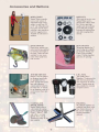
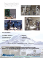
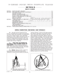
Service Manual# M5-0611
OPERATION AND MAINTENANCE MANUAL
FOR
SHARPE M5 PORTABLE MIXERS
TABLE OF CONTENTS
PAGE
Section 1: Initial Inspection, Receiving and Storage……………… 1
Section 2: Mounting…………………………………………………..
1
Section 3: Installing the Mixer Shaft & Impeller……………………. 1
Section 4: Positioning……………………………………………….. 2 & 5
Section 5: Motor Connections……………………..………………… 2
Section 6: Lubrication………………….……………………………… 3
Section 7: Operation…………………….……………………………. 3
Section 7.1: Start-Up Checklist……………………………………… 4
Section 8: Quick-Release Mount..…………………………………..
5
Section 9: Direct Drive Disassembly……………………...………… 6
Section 9.1: Direct Drive Parts List……………………...………….. 7
Section 9.5: Gear Drive Parts List……...………………..………….. 8
Section 10: Gear Drive Disassembly…….……………..…………… 9
Section 11: Trouble Shooting Guide………………………………… 10
Section 12: Accessories and Options……………………………….. 12
Service Manual# M5-0611
www.sharpemixers.com
(800) 237-8815
FAX (206) 767-9170
OPERATION and MAINTENANCE INSTRUCTIONS for
SHARPE PORTABLE MIXERS
SECTION 1
INITIAL INSPECTION, RECEIVING AND STORAGE
1.1 Immediately upon receipt of the equipment
check the crating and contents for any damage that
may have occurred in transit. Report any damage
immediately to the carrier and to Sharpe Mixers.
Check against packing slip to be sure that all parts
were received. Report missing items to Sharpe Mixers.
Store the entire unit off the floor, covered with plastic,
and use desiccants to reduce moisture build-up. Do
not seal the plastic cover as this traps moisture. If the
motor shows signs of moisture absorption before startup, dry the motor out by applying 10% voltage on two
leads (if in doubt, measure resistance in windings).
This should give approximately 50% rated current.
1.2 Mixer and impellers are normally packed toThere are also sprays available to help dry out motors.
gether. The mixer shaft is packed in a separate
Relubricate motor before start-up when in storage six
container. Impellers are usually banded to mixer drive months or more. When gear drive models have been
or lag-bolted to drive skid. If space allows, keep
in storage for more than a year, the condition of the
shipping containers for possible future use.
gear lubricant must be inspected (see Section 6,
Lubrication).
1.3 Storage: Store mixer in a clean dry location, with
circulating air free from wide variations in temperature. Electric motors are easily damaged by moisture.
SECTION 2
MOUNTING
2.1 Set the mixer drive on the tank mounting surface
and tighten the clamp screw until stabilized. Check
to see that both the horizontal and vertical mounting
surfaces are in even contact. Tighten the clamp
screw securely. If the unit is supplied with a cup plate
instead of a C-clamp, bolt the cup plate securely in
place using four (4) 3/8" hex bolts ( see page 6 for cup
plate dimensions). Lock washers or double-nutting is
recommended to prevent bolts from loosening by
equipment vibration.
2.2 Mounting structure must be stable. If mounting to
a flexible tank wall or other unstable support, mixer
loads may cause dismounting, damage to the tank,
or other hazards. A free standing mounting bracket
may be fabricated, or ask for Bulletin MS9-6 describing
the portable mixer stands we have to offer.
SECTION 3
INSTALLING THE MIXER SHAFT & IMPELLER
(refer to pages 6 or 7)
WARNING: Always lockout power before installing
or removing mixer shaft or impeller.
3.1 The mixer shaft will have one end (marked "motor
end") ground to fit the drive bearing and coupling.
Slide the impeller(s) onto the opposite end with the
concave side of the blades facing AWAY from motor
end of shaft (for standard clockwise rotation, down
pumping only). A single impeller is mounted at the
end of the shaft. The upper impeller (if supplied) is
normally mounted a minimum of 2 impeller diameters
below the liquid surface. Tighten the set screws
securely. High horsepower units will have “divots” into
which the set screws must be tightened.
4366 - 1 - 0499
1
3.2 Remove the service window 512 from the
mixer nosecone so the bearing and coupling are
visible (see page 6 or 7). Rotate the coupling until the
two clamping bolts 651 are accessible. Install the
mixer shaft (with the end marked "motor end") up
through the lip seal, bearing, and into the drive
coupling 650 . Do not use oil to aid in assembly or
slippage may occur. Using the 3/16" hex wrench
supplied, TIGHTEN THE TWO BOLTS IN THE COUPLING
651 , gripping the mixer shaft in position. Tighten
SECURELY as these bolts transmit the mixer torque.
TIGHTEN THE TWO BEARING SET SCREWS
310 , using
the 1/8" hex wrench provided.
SECTION 4
POSITIONING
4.2 Rotate the mixer shaft by hand to assure that the
4.1 The “ball and socket” mounting design allows for
360o rotation of the mixer drive, and 90o adjustment of impeller runs free of any obstructions in the tank, i.e.,
the shaft angle. The best positioning for your particular baffles or heating coils, etc.
application depends on your tank shape and process
See page 5 for instructions on adjusting the M5
requirements. Refer to the illustrations below:
Quick-Release Mounting System
10 -20
10 -20
R/2
2D
R
D
4.3 If tank diameter is approximately
equal to liquid depth, use one propeller, placed at least 2 propeller
diameters from the bottom of the tank.
4.4 Position the mixer shaft 10o to 20o
off vertical.
4.5 Pivot mixer clockwise until shaft
points 10o to 20o off tank centerline,
and the propeller is about halfway
from center to edge of tank.
>1.5D
D
4.6 If tank height is greater than 1.5 x
the diameter, use two props. Position
lower prop at least 2 prop diameters
from bottom. Place upper prop
halfway between bottom and top of
liquid level.
4.7 For drawing down light powders,
position mixer in center of tank to
create a vortex. A vortex may not be
recommended for other products.
Depth of propeller will vary vortex.
4.8 Baffles may be used to prevent
vortexing when mixer is mounted on
center. Baffling may not be required
with more viscous products.
SECTION 5
MOTOR CONNECTIONS
5.3 Electric motors - single phase: If your mixer is
supplied with a single phase motor it will normally be
wired by the factory with a ten foot cord and an on/
off switch. If no cord or switch is provided refer to the
wiring diagram on the motor for correct connections.
Check that the switch is in the off position before
plugging the cord into a 110 volt outlet. Check
rotation!
WARNING: High voltage and rotating parts can
cause serious or fatal injury. Electric machinery can
be hazardous. Installation, operation, and maintenance of electric machinery should be performed
by qualified personnel. Familiarity with NEMA safety
standards, National Electric Code and local building
codes are required.
5.4 Electric motors - 3 phase: Motors requiring 3
phase power must be wired according to the wiring
diagrams on the motor. Interchange lines if necessary
for proper rotation. Size heaters for correct amperage ( see motor nameplate ) to provide overload
protection.
5.1 Wiring: Starting and overload control devices must
be matched to motor rating. Follow control
manufacturer's instructions for proper connections
and installation.
5.2 Electrical connections must conform to National
Electrical code and all local regulations. Line voltage
and wire capacity must match motor rating stamped
on motor nameplate.
5.5 Electric Variable Speed: Electric motors using an
SCR or variable frequency controller must be wired
4366 - 2 - 0499
2
following the instructions supplied with the controller.
Many adjustments are often required to the controller
and instructions must be read carefully before
applying power. Adjust the controller to limit the
maximum speed to the motor nameplate R.P.M. ( or
refer to the motor speed in the data sheet at the front
of this manual ).
line ahead of the motor to prevent damage. Use
the same or one pipe size larger than intake port of
motor. A regulator may be used to govern the
mixer speed. Install the air line in the proper port to
provide proper rotation. These accessories are
available from Sharpe Mixers.
WARNING: Damage to equipment or serious
injury to personnel can result if speed limitations are
not followed.
5.6 Air motors: Air driven mixers must always have a
filter, lubricator, and moisture trap installed in the air
SECTION 6
LUBRICATION
6.1 Your mixer has been lubricated at the factory with
the proper type and amount of lubrication for normal
service (gear drive units only). This lubricant needn’t
be changed under normal conditions for a period of
3 years. Under extreme conditions it is recommended
that the lubricant in the gear box be changed more
SERVICE
frequently. Remove motor to repack gearbox. Refer
to the chart below for the lubricant recommended
for temperatures in your area. (When changing to a
different lubricant, clean gearbox with mineral spirits
before repacking.)
LUBRICANT
CHEVRON EQUIVALENT
32oF (0oC) and up
Oil based EP
Semi fluid grease
Black Pearl NLGI 1
(standard from factory)
Down to -20oF (-29oC)
and up to 300°F (149°C)
Synthetic EP
ULTI-PLEX synthetic grease EP
Food grade
Food grade EP-2
Chevron FM grease EP2
6.2 Electric motor bearings are usually sealed and
need no relubrication. If zirc fittings are present
relubricate a No. 2 consistency lithium soap base and
petroleum compound every 6 months to 3 years
depending on usage. Open and clean drains. Add
grease until new grease is forced out drain. Remove
excess grease and replace input plugs. Run motor
one half hour before replacing drain plugs. Mixer
shaft bearings are sealed and need no relubrication.
6.3 Air motor lubrication: The lubricator needs to be
adjusted to feed one drop of oil for every 50 -75 CFM
of air through the motor. Use a detergent SAE #10
automotive engine oil.
SECTION 7
OPERATION
excessive vibration of the equipment. When mixing
products of dissimilar viscosities and/or specific
gravities the lighter or less viscous material should be
introduced first. Gradually add the heavier material
or powders into the center of the tank while the
agitator is running. Never dump large amounts of
powder or solids into the mixing tank. This may create
clotting or “sanding in” of impeller and cause damage to the equipment.
WARNING: High voltage and rotating parts can
cause serious or fatal injury. Lockout power before
servicing.
7.1 Rotate mixer shaft by hand to check shaft
straightness and to assure that the impeller is free of
any obstructions in the tank.
7.2 Never operate mixer without the lower impeller
immersed in the liquid by at least one prop diameter.
Never operate mixer if fluid falls below this level.
CAUTION: Do not start mixer with impeller buried
in solids or with liquid solution solidified. Damage
will occur.
7.3 Unless otherwise indicated on the DATA SHEET in
front of this manual, the propeller rotates clockwise
7.5 If impeller is buried in solids prior to starting mixer,
(pumping down) when viewed from above. Opposite solids must be dispersed. This may be achieved with
rotation may cause overload and inefficient mixing.
an air hose, a recirculating pump, or a large stirring
stick if necessary.
7.4 Optimum mixing is achieved by following the
positioning recommendations in Section 4. Vortexing
7.6 Shaft vibration is normal with a portable mixer.
may occur if liquid level is too close to the upper
The rubber vibration pad in the mixer mount is designed to allow shaft vibration without damaging the
impeller. This will cause aeration of the product and
mixer drive.
4366 - 3 - 0499
3
Excessive vibration may be caused by a shaft or
impeller which has been bent, possibly in shipment.
Consult factory for recommendations.
7.8 Do not drive air motors above 1750 R.P.M.. See
Figure 7.1 and 7.2 for proper air consumption and
pressure. See DATA SHEET for motor size.
7.7 Keep motors free from oil, dust, dirt, water, and
chemicals. Keep air intakes and outlets free from
foreign material. Electric motors supplied, although
designed for outdoor use, may be damaged due to
weather. A rain hood or similar protection may be
necessary to prolong motor life.
7.9 Regular maintenance is the best assurance of
trouble free, long life mixer operation. Inspect and
relubricate at regular intervals. Frequency and
thoroughness depends on operation, nature of
service, and environment.
6 AM AIR MOTOR @ 1750 R.P.M.
4 AM AIR MOTOR @ 1750 R.P.M.
H.P.
0.25
0.5
0.75
1.0
1.2
H.P.
0.5
1.0
1.6
2.2
2.6
C.F.M.
14
22
30
39
48
C.F.M.
23
39
53
68
82
P.S.I.
20
40
60
80
100
P.S.I.
20
40
60
80
100
FIGURE 7.1
FIGURE 7.2
7.10 Start-Up Checklist
Prior to and during start-up please check that the following things have been done:
a. Manual has been read and followed
b. Shaft coupling bolts tight (3/16" hex “tee” wrench)
c. Bearing setscrews tight (1/8" hex allen wrench)
d. Sufficient weather protection for motor (if outdoors)
e. Wiring correctly installed, grounded and
insulated
f.
Correct heaters installed for overload protection
g. All mounting bolts tight
h.
Impeller bolts tight
i.
Impeller(s) installed correctly (see Section 3)
j.
Impellers spaced correctly (if two or more)
for maximum and minimum liquid level
(see Section 3)
k.
Impeller immersed in liquid
l.
Proper type and amount of lubricant
(when serviced; see Section 6)
m.
n.
o.
Proper shaft rotation (clockwise looking down, unless otherwise noted)
Correct voltage/amperage upon starting
(check against motor nameplate data)
Record: __
Excessive noise after start-up?
Record: ____
Volts______Amps
_db @ 3ft
p. Excessive vibration of tank or support?
INSPECTOR_____
_____
_
_____________ DATE____________
4366 - 4 - 0499
4
M5 QUICK-RELEASE MOUNTING SYSTEM - Installation Procedure
Sharpe Mixers’ M5 Quick-Release Mounting System is relatively simple to assemble, but it won’t work
properly if not installed & adjusted correctly. The following procedure will help this installation:
4)- The Swivel Screw must be loose enough at this
point so the Nosecone can still be rotated and
moved around in the Clamp.
1)- “Loosen” the handwheel fully counterclockwise
until it stops, pulling the WedgeLOCK in the
direction of the gray arrow, as shown.
2)- Install the assembly with the Swivel Screw
through the slot in the nosecone swivel mount.
Install the Vibration Pad over the screw, and thread
the screw into the Clamp.
5)- Turn the Handwheel clockwise to tighten the
WedgeLOCK and secure the mixer in position.
3)- Push the nosecone into the Clamp to stretch the
Vibration Pad enough so the Screw will reach the
tap in the Clamp. Continue to push the Nosecone
into the Clamp and tighten the Swivel Screw until all
slack is removed and the bolt is finger tight.
www.sharpemixers.com
NOTE: If the mixer is still loose when the
handwheel is tightened, loosen the handwheel fully
counter-clockwise and re-tighten the Swivel Bolt.
This adjustment is especially necessary when the
Vibration Pad is new and is not yet formed to fit into
the Clamp.
P.O. Box 3906, Seattle WA 98124
5
(206) 767-5660
SECTION 9
DIRECT DRIVE DISASSEMBLY
8.1 Disconnect power from mixer.
8.4 Reinstall the bearing from the inside of the
nosecone, using a LOCTITE sealant (271 or better) to
hold the bearing in place. The lipseal 360 must be
installed from the outside of the nosecone into
position as shown in the drawing.
WARNING: High voltage and rotating parts can
cause serious or fatal injury. Lockout power before
servicing.
8.2 Remove the service window 512 . Loosen the
two bearing setscrews 310 and the two lower
coupling bolts 651 and remove the mixer shaft.
Remove the four 3/8" bolts mounting the motor to the
nosecone and then the two may be separated.
8.5 To reassemble, reverse procedure, being sure
shaft has full engagement in the split coupling 650
and all fasteners are tight.
8.3 Bearing and seal removal: Place the mixer
nosecone in a bench press with the motor mounting
face down. Use a 1-1/2" diameter arbor in the press
on top of the lip seal 360 and press the lip seal and
the bearing 301 down and out of the nosecone.
STANDARD DIRECT DRIVE IMPELLERS
MARINE PROPELLER
HIGH SHEAR
4366 - 6 - 0499
6
DIRECT DRIVE PARTS LIST
100
511
521
518
512
519
650
513
310
514
301
600
360
100 - MOTOR
301 - BEARING*
310 -(2) S. S. BRASS TIPPED SET SCREWS
360 - LIP SEAL*
511 - NOSECONE
512 - SERVICE WINDOW
513 - SERVICE WINDOW GASKET
514 - C-CLAMP
515 - CLAMP SCREW
516 - CLAMP SCREW SWIVEL END
518 - QUICK-LOCK
SWIVEL WASHER
MOUNTING ASSEMBLY
519 - VIBRATION PAD
520 - CUP PLATE
521 - SWIVEL BOLT
600 - MIXER SHAFT*
650 - COUPLING*
651 - (4) SPLIT COUPLING BOLTS
700 - IMPELLER (SEE OPPOSITE PAGE)
516
515
3-3/4" MAX
520
* NOTE - WHEN ORDERING PARTS, GIVE SERIAL NO. AND SHAFT SIZE.
DENOTES RECOMMENDED SPARE PART
(4) 7/16" Ø ON 3-1/4" SQUARE SPACING
4366 - 7 - 0499
7
GEAR DRIVE PARTS LIST
100
211
118
233
232
203
205
231
204
230
104
201
227
511
221
223
650
SEE DIRECT DRIVE
FOR C-CLAMP & CUP - PLATE
DETAILS
512
513
651
310
301
600
360
100 - MOTOR
104 - PINION GEAR KEY
118 - C-FACE GASKET
201 - BEARING PLATE
203 - GEAR HOUSING
204 - PINION GEAR
205 - HELICAL GEAR
211 - GEAR SHAFT
221 - GEARBOX BEARING
223 - LIP SEAL
227 - GEARBOX GASKET
230 - BEARING RETAINER
231 - GEAR SPACER RING
232 - STAR WASHER
233 - GEAR NUT
301 - SHAFT BEARING*
310 - (2) S. S. BRASS TIPPED SET SCREWS
360 - SHAFT LIP SEAL*
511 - NOSECONE
512 - SERVICE WINDOW
513 - SERVICE WINDOW GASKET
600 - MIXER SHAFT*
650 - COUPLING*
651 - (4) SPLIT COUPLING BOLTS
* NOTE - WHEN ORDERING PARTS, GIVE SERIAL NO. AND SHAFT SIZE.
DENOTES RECOMMENDED SPARE PART
4366 - 8 - 0499
8
SECTION 10
GEAR DRIVE DISASSEMBLY
9.4 To remove pinion gear 204 from the motor
shaft, first clean the pinion gear and motor shaft of
grease. Support the motor shaft with a soft block to
prevent damage when removing the pinion gear.
The pinion gear may be removed from the motor
shaft using a gear puller. Use care to not chip the
teeth of the hardened gear. Apply heat to break the
adhesion of the Loctite®.
9.1 Disconnect power from mixer.
WARNING: High voltage and rotating parts can
cause serious or fatal injury. Lockout power before
servicing.
9.2 Remove the service window 512 . Loosen the
two bearing setscrews 310 and the two lower
coupling bolts 651 and remove the mixer shaft.
9.3 Remove the three motor bolts and the motor may
be lifted off the gear head assembly. Remove the
four (4) 3/8" gear head assembly bolts and lift off the
gearbox housing 203 . The bearing plate 201
may now be removed with the gear, gear shaft and
coupling assembled. Clean the assembly of grease
and rinse with mineral spirits. Handling the gear shaft
sub-assembly is best accomplished using a piece of
round bar the same diameter as the mixer shaft.
Clamp the round bar in a bench vise and tighten the
drive coupling 650 onto the round bar. If a round
bar is not available clamp the coupling in the vise
using two pieces of wood so as not to damage the
coupling. To remove the gear nut 233 first bend
down the locking tab on the star washer from the slot
in the gear nut. Using a spanner wrench, loosen the
gear nut from the shaft. Remove the gear nut and
the star washer. The slow speed gear 205 may be
removed using a gear puller if it is too tight to remove
by hand. Gear teeth are hardened and are easily
chipped. Use care when handling. Loosen the upper
two coupling bolts and remove the gear shaft/
bearing plate assembly from the coupling. Place the
subassembly in a press with the threaded end of the
shaft pointing up. Remove the spacer ring
231
from the gear shaft. Press the gear shaft 211 down,
out of the bearing plate. Remove the four 1/4" cap
screws and the bearing retaining ring 230 . Turn
the bearing plate upside down so that the lip seal
223 is on top. Using a 2" diameter arbor press the lip
seal and the bearing out of the bearing plate. See
Section 8.2 for removal of bearing and lipseal in the
nosecone.
9.5 To reassemble a new gear on an existing motor,
clean all parts and trial fit the pinion gear on the shaft.
Never pound the pinion gear into place. Assemble
gear and key flush with the end of the motor shaft
using Loctite® # RC-680 compound. Remove any
excess Loctite® from the gear, especially from the
gear teeth. If replacing both the motor and pinion
gear, Sharpe Mixers will normally supply the motor with
the pinion gear installed. Pack the gearbox full with
the appropriate lubricant (see Section 6).
HYFLO II ENERGY EFFICIENT IMPELLERS ARE
STANDARD ON GEAR DRIVE PORTABLE MIXERS
Always reference mixer serial number when making
a parts inquiry or placing an order. This serial
number is located on the Sharpe Mixer nameplate
and on the front cover of the service manual.
4366 - 9 - 0499
9
SECTION 11
TROUBLE SHOOTING GUIDE
PROBLEM
POSSIBLE CAUSE
POSSIBLE SOLUTION
•Shaft will not fit into drive
•Wrong end of shaft
(only one end fits)
•(2) bearing set screws 310
extend into bearing bore
•(2) coupling bolts 651 too tight
•Shaft over size
(proper dia. 0.001" - 0.002"
under nominal dia.
•Wrong size shaft 600 ,
coupling 650 ,
or bearing 301
•Damaged shaft 600 ,
coupling 650 ,
or bearing 301
•Install end marked
"motor end"
•Loosen set screws
•Mixer will not
start
•Incorrect wiring
•Loose connections
•Blown fuse
•Incorrect voltage
•Mechanical jamming
•Water damage to motor
•Wrong size heaters in starter
•Mixer will not
reach correct
speed
•Overload of motor
•Loose drive coupling bolts 651
•Air motor vanes/ports dirty
•Insufficient pressure for air motor
•Loosen bolts
•Measure and consult factory
•Consult factory
•Consult factory
•Check wiring diagram
and wire correctly
•Check and tighten connections
•Replace fuse
•Wire for correct voltage
•Free all debris for rotation
•Service or replace motor
•Replace heaters
•Check amperage against
nameplate data
•Check coupling bolt tension
(coupling and/or shaft maybe
damaged if mixer has been run
with slipping coupling)
•Flush air motor with noncombustible solvent & relubricate
•increase air line, compressor size,
decrease air compressor
distance from air motor
•See “Mixer will not start”
•Motor runs hot
•Low or high voltage
•Amperage overload
•Product too viscous
•Wire for correct voltage
•Contact factory
•Check viscosity and specific
gravity of product (consult factory)
•Restricted ventilation
•Frequent starting and stopping
•Clear vents
•Check with factory - a special
motor may be required
•Consult electrician
•Unbalanced voltage
between phases
•Incorrect rotation
•Air motor not lubricated properly
•Impeller(s) upside-down
•Exceeding maximum speed
•Change motor leads per
nameplate instructions
•Lubricate (see Section 6)
•Reinstall in correct position
•Adjust variable speed drive to
limit R.P.M.
4366 - 10 - 0499
10
PROBLEM
POSSIBLE CAUSE
POSSIBLE SOLUTION
•Noisy
•Loose drive coupling
bolts 651 or bearing
set screws 310
•Insufficient lubricant
•Foreign material in
lubricant
•Incorrect lubricant
•Worn or faulty bearings / gears
•Check and tighten coupling
bolts and set screws
•Dry lip seal 360
•Bearing failure
in spool
•High temperature product
•Excessive overhung load
•Water damage
•Fill proper amount of lubricant
•Change lubricant
•Change to correct lubricant
•Check bearings/gears
replace if necessary
•Apply lubricant to lip seal
•Provide heat shield
•Consult factory
•Replace bearing
(check all other parts)
•See all items under “Noisy”
•Gear failure
•Excessive loading
(check amps)
•Lack of (or improper)
lubrication
•Start-stop-start loading
(product burying
impeller with solids)
•Foreign material in lubricant
•Oil leakage
•Excessive lubricant
•Damaged/broken gasket
•Loose bolts around
side plates
•Seals worn or
damaged
•Shaft vibration
•Impeller not immersed in liquid
•Impeller too close to surface
•Bent mixer shaft
•Unstable mounting platform
•Bent or uneven impeller blades
•Worn or damaged drive bearings
or coupling
•Operating at critical speed
4366 - 11 - 0499
11
•Consult factory
•Fill with recommended
lubricant or equivalent
(see Section 6)
•Free impeller of any solids at
start-up (pre stir with air
hose or paddle)
•Replace lubricant
•Check manual for proper
amount lubricant and
drain excess
•Replace gasket
•Check and tighten bolts
•Replace seals
•Fill tank
•Fill tank or lower impeller
(see Section 3)
•Consult factory
•Reinforce platform
•Consult factory
•Replace damaged parts
•Consult factory
S H A R P E M I X E R S, INC.
STANDARD TERMS & CONDITIONS OF SALE
In consideration of the mutual promises and agreements contained
herein, the buyer (“Buyer”) and SHARPE MIXERS, INC. (“SHARPE” or
“WE”) hereby agree to the following terms and conditions; provided,
that the terms and conditions (including the price quotations) shall only
become binding on SHARPE upon the mailing or other transmission of
SHARPE’s Acknowledgment Form as described in Section 6 Below.
1. Warranty
We warrant that we shall repair or replace, without additional charge, or
refund the price of, the products provided to the Buyer herewith (collectively
“Mixer”) if the Mixer (a) is defective in materials or workmanship, (b) fails to
provide the process results specified in SHARPE’s proposal (“Proposal”), or
(c) if no process results are specified in SHARPE’s proposal, Mixer fails to
provide the process results described in Buyer’s written specifications. While
we warrant that the Mixer is made from the materials specified in the Proposal
or its commercial equivalent, WE DO NOT GUARANTEE THE MIXER
AGAINST CHEMICAL ATTACK OR OTHER DETERIORATION DUE TO
EXPOSURE.
THE FOREGOING WARRANTIES EXTEND ONLY FOR TWELVE (12)
MONTHS AFTER FIRST INSTALLATION OF THE MIXER AT BUYER’S
FACILITY OR FOR EIGHTEEN (18) MONTHS AFTER ITS SHIPMENT
FROM SHARPE’S FACILITY, WHICHEVER PERIOD IS SHORTER.
ADDITIONALLY, SUCH WARRANTIES ARE EXPRESSLY IN LIEU OF ALL
OTHER WARRANTIES, EXPRESSED OR IMPLIED, ORAL OR WRITTEN,
INCLUDING THE WARRANTIES OF MERCHANTABILITY AND FITNESS
FOR A PARTICULAR PURPOSE, AND OF ALL OTHER OBLIGATIONS OR
LIABILITIES ON THE PART OF SHARPE. THESE WARRANTIES SHALL
NOT APPLY TO FAILURES RESULTING FROM (A) NORMAL WEAR AND
TEAR, (B) ACCIDENT, NEGLIGENCE, ALTERATION, ABUSE, MISUSE OR
USE INCONSISTENT WITH ANY INSTRUCTIONS PROVIDED AS TO
STORAGE, HANDLING, MAINTENANCE, LUBRICATION, INSTALLATION,
STARTUP, OPERATION AND SAFETY, (C) IMPROPER INSTALLATION
AND/OR (D) INACCURATE AND/OR INCOMPLETE SPECIFICATIONS,
DESIGN CONDITIONS OR OTHER DATA FURNISHED BY OR ON
BEHALF OF BUYER. WE MAKE NO WARRANTY WHATSOEVER WITH
RESPECT TO ACCESSORIES OR PARTS NOT SUPPLIED BY SHARPE.
2. LIMITATION OF REMEDIES
Buyer’s remedy for breach of any of the foregoing warranties shall be
limited to those set forth in Section 1 above; provided, WE will not be
responsible for removal, loading, installation, freight or similar related
expenses in connection with any replacement, repair or return. The
determination of which such remedy shall be applicable shall be determined
by SHARPE, in its sole discretion. THE ABOVE STATED REMEDIES ARE
SHARPE’S ENTIRE AND EXCLUSIVE LIABILITIES AND BUYER’S
EXCLUSIVE REMEDIES FOR ANY CLAIM FOR DAMAGES IN
CONNECTION HEREWITH. By way of illustration and not limitation, in no
event shall we be liable for any direct, indirect, special or consequential
damages or delay whatsoever or loss of use, and SHARPE’S liability under
no circumstance will exceed the contract price for the Mixer for which liability
is claimed. All claims for breach of any of SHARPE’S warranties shall be
barred unless Buyer notifies SHARPE in writing within 30 days of discovery of
the breach. WE shall not be responsible for any repairs performed by third
parties unless the extent, terms and costs of such repairs are authorized by
SHARPE in writing in advance. Buyer shall be solely responsible for any
agreement that Buyer makes with its customers which is contrary to the
foregoing provisions.
3. DELIVERY / SHIPMENTS
Unless otherwise quoted, shipments are F.O.B. shipping point. Risk of
loss and damage to the Mixer shall pass to Buyer upon delivery to the carrier
and at such time, Buyer shall be solely responsible for the Mixer. We will
make every effort to ship on the date specified in the contract; provided, that
such dates are approximations only. We will not be liable for or penalized as
a result of delays in shipment, for any cause, including but not limited to
delays that are beyond our control.
Buyer may not defer shipments beyond the specified shipment date after
commencement of manufacture without SHARPE’s written consent. When
shipping is deferred for Buyer’s convenience, due to lack of shipping
instructions, failure to complete credit arrangements satisfactory to SHARPE
or late delivery of customer supplied material, Buyer agrees to pay
reasonable storage charges, interest and any other expenses incurred by
SHARPE due to the delay. Orders on which delivery is deferred shall be
invoiced upon completion of manufacture and are subject to finance charges
of 1.5% per month.
4. CHANGES
Any changes requested by Buyer and approved by SHARPE with respect
to the Mixers shall be subject to adjustments to the delivery schedule and/or
price of the Mixer, as shall be determined by SHARPE, in its sole discretion.
5. PRICES / PAYMENT
Price quotations set forth on any Proposals from SHARPE are for informational
purposes only and represent an estimate of the prices that will be available to Buyer.
Such price quotations are not binding upon SHARPE until an authorized
representative of SHARPE (at SHARPE’s home office in Seattle, Washington)
accepts and confirms in writing any offer to purchase submitted by the Buyer by way
of a Contract Acknowledgment. Prices set forth on SHARPE’s Acknowledgment
Form shall be binding with respect to the order described therein; provided, that
orders placed “on-hold” or held over 3 months or more (i.e., awaiting Buyers
approval) are subject to price adjustments.
Upon approval of Buyer’s credit by SHARPE, unless stated otherwise on the face
hereof (in which case such terms shall control), terms are net 30 days, F.O.B.
Seattle, WA-Freight Collect; provided, that if, in the sole discretion of SHARPE, (a)
the order is for a customized or otherwise unique Mixer or is of a substantial
magnitude or for any other reason, or (b) Buyer’s credit is not approved or the
financial condition of Buyer becomes such that it does not justify continuance of
production, shipment or delivery on the terms of payment specified, we may require
full or partial payment in advance or payment upon delivery. Prices do not include
customs, duties or taxes such as sales, use, excise, retailer’s occupation or similar
taxes, and if, in connection with this transaction, SHARPE is subject to any such
customs, duties or taxes, the same will be added to the purchase price to be paid by
Buyer. If payment is not made when due, Buyer shall pay SHARPE a finance charge
of 1.5% per month and (ii) ALL WARRANTIES PROVIDED BY SHARPE
HEREUNDER SHALL IMMEDIATELY BE NULL AND VOID. All price lists and
discount schedules are subject to change without notice.
6. ACCEPTANCE
All orders by Buyer are subject to acceptance by SHARPE’s authorized
representative at SHARPE’s main office; provided, that any terms or conditions which
are additional or different to the terms and conditions set forth herein or which may
have been included in any communication between Buyer and SHARPE, whether
written or oral, are hereby objected to by SHARPE and shall not be effective or
binding upon SHARPE unless specifically assented to by a duly authorized officer of
SHARPE in Writing. No waiver, alteration or modification of any of the provisions
hereof shall be binding on SHARPE unless made in writing and signed by a duly
authorized officer of SHARPE. Buyer’s acceptance of delivery of the Mixer shall
constitute full acceptance of all of the terms and conditions set forth herein. The
failure of either party to enforce any of its rights hereunder shall not constitute a
waiver of such rights or of any other rights hereunder. The terms and conditions of
the Acknowledgment contain the entire agreement of the parties. Clerical and
typographical errors are subject to correction.
7. CANCELLATION CHARGES
Orders placed by Buyer may not be canceled without SHARPE’s written consent.
Buyer agrees to indemnify SHARPE against all loss, damage or expense incurred
due to cancellation including, but not limited to the cost of special materials, nonresalable goods, completed or in process, labor, freight, engineering time, overhead
and profit. A minimum charge of 20% will be applied in the event of a cancellation.
8. OCCUPATIONAL SAFETY AND HEALTH ACT OF 1970
WE do not warrant or represent that any of SHARPE’s products by themselves or
in a system or with other equipment will conform to or comply with the provisions of
the Occupational Safety and Health Act of 1970 and the standards and regulations
thereunder, or any other federal, state, or local law or regulation of the same or
similar nature.
9. PATENTS
SHARPE certifies that to its knowledge the Mixer does not infringe upon any
patents granted to others by the United States of America. WE do not assume any
responsibility or liability for any claim of infringement brought against the Buyer, its
successors, assigns, customers or users of the Mixer.
10. ATTORNEY FEES
In the event an arbitration, suit or action is brought by any party under this
agreement to enforce or interpret any of its terms, or in any appeal therefrom, it is
agreed that the prevailing party shall be entitled to reasonable attorneys fees to be
fixed by the arbitrator, trial court, and/or appellate court. Buyer shall be responsible for
any and all costs of collection incurred by SHARPE in connection herewith, including
attorney’s fees and costs.
11. JURISDICTION/VENUE
This agreement shall be binding upon the successors and assigns of SHARPE and
Buyer, and shall be deemed entered into at Seattle, Washington, and shall be
governed by and construed in accordance with the laws of the State of Washington. In
the event of litigation between the parties to enforce any terms of the agreement, the
parties agree that venue shall be the Superior Court of the State of Washington for
-------------------------------King County.
Document #0051848.05
December 5th, 2006
Sharpe Mixers manufactures a full line of liquid
mixing equipment including top and side entry
mixers and custom designs to meet specific
requirements. Contact your local representative
or visit our web site to find out more
Applications
• FOOD AND BEVERAGE
• CHEMICAL
• PHARMACEUTICAL
• MUNICIPAL
• PULP AND PAPER
• WASTE TREATMENT
• PETROLEUM
• MINING
Built with pride in the United States of America
Sharpe Mixers’ strength originates from the teamwork and energy of our people experienced and innovative employees dedicated to providing exactly what our customers demand:
superior equipment, excellent service and timely delivery at a competitive price.
P.O. Box 3906 Seattle, WA 98124
Tel: 800-237-8815 • Fax: 800-767-5670
Internet: http://www.sharpemixers.com
16
#PORT1201
ServiceBrochure
Manual#
M5-0611