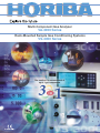
1
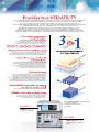
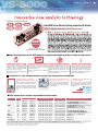
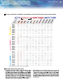
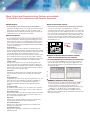
Multi-Component Gas Analyzer
VA-3000 Series
Rack-Mounted Sample Gas Conditioning Systems
VS-3000 Series
01
From environmental monitoring to developing new energy sources and chemicals for the new era, gas analysis systems are faced with needs
and challenges that have changed dramatically over time. Responding to these new needs, Horiba has developed the VA-3000,
the versatile gas analyzer that’s ready for the future. A single analyzer is now capable of measuring a wider selection
of gas components utilizing many different types of sensor technology. Non-dispersive infrared (NDIR) modules are available to measure gases
such as CO, CO2, NO, N2O, CH4, SO2 and others. A chemiluminescent sensor module may be included to measure
NO or NOx with a standard converter. And four different types of sensor modules are available to measure O2 – galvanic,
paramagnetic, zirconium oxide or magnetopneumatic. Designed to be compact and lightweight, the VA-3000 may have up to
three sensor modules installed in a single analyzer case. This unique feature means the VA-3000 can be used today for a broad range
of applications including research and development or environmental pollution monitoring, where efficiency and space-saving are crucial.
A single VA/VS-3000 analyzer is capable of simultaneously
measuring multiple gas components such as CO, CO2, O2, NOx, SO2,
CH4, N2O and other gases. With the VS-3000 sampling system,
the VA/VS-3000 will meet the needs of a diverse range of applications.
Development of smaller sensor modules now makes it possible to install up to
three sensor modules in a single unit. You can install three NDIR modules in a single
case or substitute a chemiluminescent or oxygen module for any of the NDIR modules.
s
ule
od
M
or
ns
Se IR
D
N
A
CL
PA nic
●M
a
alv ia etic
●G
on n
rc mag
i
●Z
a
ar
●P
●
●
The VA-3000 also features dynamic ranges up to 20x the base (first) range.
And the dynamic range can be further expanded by installing multiple sensor
modules for the same component gas in a single analyzer case.
Now a single unit can perform measurements over a wide range from ppm to
100 percent concentrations. With our diversified lineup of modules,
you can always choose the optimum range for your application.
The VA-3000 achieves repeatability of ± 0.5% of F.S.R. (Full Scale Range),
linearity of ±1.0% F.S.R., and drift of less than ±2.0% per week without requiring
recalibration with a gas standard saving you money. For optimum precision,
use the auto daily calibration feature, to virtually eliminate drift. Or specify the optional gas
filled calibration cell that is used to routinely check and adjust the calibration
of the NDIR modules without the need for external gas cylinders. With these features,
high precision measurement is maintained throughout the entire measurement range.
it
is
s
aly
Un
An
nit
gU
n
pli
Analog outputs are also available for direct connection to control systems.
m
Sa
As an expert on gas analysis systems, with a wealth of experience,
Horiba can provide consulting services and/or appropriate hardware
for pretreatment of even the most difficult sample gases.
VA-3000
The VA-3000 and VS-3000 are UL/CSA approved.
UL Code No. UL60101A-1
CSA Code No. C22.2 No.1010.1
TUV Pending
Determines gas concentrations.
VS-3000
Conditions sample gases that contain
particulates, water vapor or acids prior
to analysis.
VA-3000 Series / VS-3000 Series 02
Some of the common gases measured
New NDIR Sensor Module utilizing proprietary IR detector
NDIR
Dual-beam Non-Dispersive Infrared Absorption Method
NEW
development
Results in compact size
and improved performance and reliability
Newly developed pneumatic NDIR detector and patented chopper provide a number of new benefits
[Reduction of warm-up time]
[Compact and light weight modules] [Virtually immune to vibration]
[Reliable noise free chopper]
The warm-up time required for the NDIR
analysis module to reach full stability and
performance has been substantially reduced
to about 10 minutes (conventional NDIR
analyzers need an hour or longer).
The small size and weight of each sensor
module allows up to three to be installed in
a single 19-inch rack mount case without
sacrificing performance.
The VA-3000 series incorporates Horiba’s
patented axis-less chopper motor to maintain
stable rotation. This assures that infrared energy
passes through the measurement and reference
cells precisely all the time. The chopper motor
design virtually eliminates noise and extends the
lifetime of the module significantly.
Measurement is now possible within minutes
after power is turned on.
The proprietary Horiba IR flow sensor in the
VA-3000 series NDIR modules is not affected
by external vibration because there are no
moving parts in the detector. This allows
stable and reliable measurement in a wide
variety of locations and environments as well
as mobile applications.
Now more instruments can be installed in
less space.
3 modules in 1 case-Compact analyzer creates new measurement possibilities
Three modules can be easily
installed in a 19-inch rack case
Small size makes the VA/VS-3000
ideal for bench top use
Multiple ranges of the same
gas are possible
Both the analysis unit and the sampling unit
can be mounted in a standard 19-inch rack.
Thanks to the small size, the VA/VS-3000
series analyzer and sampling conditioning
system is ideal for use on a bench top in a
crowded R&D lab.
Up to three of the same sensor modules (NDIR)
can be installed in a single analyzer case. This
expands the dynamic range that can be used to
measure a gas.
Up to three components can be simultaneously
measured in a single analyzer unit. A broader
range of gases can be measured in a smaller
space.
Wide measurement ranges are provided for each module.
Measurement
method
NDIR
CLA
MPA
Galvanic
Zilconia
Paramagnetic
Component
Standard
Minimum range Maximum range
Zero and span drift
Repeatability
Example of ranges (See Notes below)
CO
0-200 ppm
0-100 vol%
±2.0% full scale per week
±0.5% of full scale
CO2
0-100 ppm
0-100 vol%
±2.0% full scale per week
±0.5% of full scale
N2O
0-100 ppm
0-5000 ppm
±2.0% full scale per week
±0.5% of full scale
CH4
0-200 ppm
0-100 vol%
±2.0% full scale per week
±0.5% of full scale
SO2
0-200 ppm
0-10 vol%
±2.0% full scale per week
±0.5% of full scale
NOx
0-20 ppm
0-5000 ppm
±2.0% full scale per week
±0.5% of full scale
(±1.0 % for 0-100 ppm)
① 0-20/50/100/200/500/1000/2000 ppm
② 0-50/100/200/500/1000/2000/5000 ppm
O2
0-5 vol%
0-100 vol%
±2.0% full scale per week
±0.5% of full scale
① 0-5/10/25 vol% ②0-10/20/50 vol%
O2
0-5 vol%
0-25 vol%
±1.0% full scale per day
±0.5% of full scale
0-5/10/25 vol%
O2
0-5 vol%
0-25 vol%
±2.0% full scale per week
±0.5% of full scale
0-5/10/25 vol%
O2
0-5 vol%
0-25 vol%
±1.0% full scale per week
±0.5% of full scale
0-5/10/25 vol%
①
②
③
④
⑤
0-100/200/500/1000 ppm (CO2, N2O)
0-200/500/1000/2000 ppm (CO, CH4, SO2)
0-1000/2000/5000 ppm/1 vol% (CO, CO2, CH4, SO2)
0-5/10/20/25 vol% (CO, CO2, CH4)
0-10/20/50/100 vol% (CO, CO2, CH4)
Note 1: Select the lowest range and maximum range ratio within the above concentration ranges according to the following conditions. [NDIR] 4 ranges with a maximum ratio between the lowest and highest range (range ratio) of 10x (or
20x as an option, although this may be limited by the cell length). [CLA] 8 ranges with a maximum range ratio of 100x (if the maximum range exceeds 2000ppm, the minimum range should be 50ppm or more).
[MPA] 4 ranges with a maximum range ratio of 10x; [Galvanic] 4 ranges with a maximum range ratio of 5x; [Zirconia] 4 ranges with a maximum range ratio of 5x; [Paramagnetic] 4 ranges with a maximum range ratio of 5x.
Note 2: Contact us if you require any ranges below the concentration ranges noted above.
Note 3: Contact us if you require measurement of special gases such as NH3 or C2H4.
03
The NOx analysis module uses the sensitive chemiluminescence method (CLA)
which permits NOx measurements in a range as low as 0 –10 ppm.
The chemiluminescence analyzer has virtually zero Interference.
Horiba design technology and experience have virtually
eliminated CO2 quenching and water vopor Interference;
operates at atmospheric pressure.
Chemiluminescence
Measurment principle
Magnetopneumatic
Measurment principle
Zirconia
MP
A
Zir
co
n
Ga ia
lva
nic
Pa
ram
ag
ne
tic
Choose from four analysis methods for the oxygen analyzer module.
Select the sensor module based on your specific requirements and
sample gas conditions.
Measurment principle
Stability by design
Performance Low-concentration gas is measured
Warm-up and startup performance is important
Flammable gas is also present
High-concentration acidic gas is also present
Sample gas Alkaline gas is also present
condition
Water in a liquid state may be contained in the gas
Sample flow rate should be minimized
Measurment principle
Galvanic
Measurment principle
Paramagnetic
Carrier gas is not available
Installation VS-3000 sample conditioning system is not used
environment
Back pressure exists
Installation environment is vibrating
Cost and Operating costs should be minimized
other points Maintenance should be minimized
Best
Can be used
Easy operation from the front panel
●Up to the three components can be measured
simultaneously with a single analyzer.
●Measure a wide range of the same gas using two
sensor modules.
●Setting measurement parameters is simple with a
push of a button on the front panel.
VA-3000 Series / VS-3000 Series 04
The free combination of modules and sampling units can satisfy diverse measurement needs.
30 0 2
30 0 3
30 0 4
30 0 5
30 0 6
30 1 1
30 1 2
30 1 3
30 1 4
30 1 5
30 1 6
30 2 3
30 2 4
30 2 5
30 2 6
31 1 1
31 1 3
31 1 4
31 1 5
31 1 6
31 2 3
31 2 4
31 2 5
31 2 6
Note: Modules to measure other gases are available.
VS-300X Standard Sampling Units
04
-30
VS
-30
03
02
VS
-30
VS
-30
01
tic
VS
ma
gne
Par
a
a
oni
Zirc
Ga
lva
ni
c
30 0 1
MP
A
CL
A
IR
ND
IR
ND
IR
ND
An
aly
sis
un
it
See Note below
05
Many Output and Communication Options are available.
To Facilitate Data Collections and Remote Operation.
●Analog
Outputs:
Two Analog outputs for each component measured by the VA-3000 are
available through a DB15 connector on the rear panel of the instrument. Each
output may be set to either 4 to 20mA or 0 to 1Vdc non-isolated. If an O2
measurement module is included in the instrument, separate outputs may be
configured by the user for the raw and O2 corrected values.
●Discrete
I/O options:
The optional VA-PIO-01 board provides 16 channels of digital inputs and 16
channels of digital outputs. The inputs require an external dry contact closure
from the users control system (some commands require momentary closures)
and the outputs are form C dry contacts rated 24V DC, 0.5A. The following
functions are provided by the optional VA-PIO-01 circuit board via three DB25
connectors on the rear panel:
Analyzer Alarm:
Activated when diagnostic values monitored in each analyzer module are
abnormal including module temperature, chopper motor failure and low sample
flow-rate. The alarm activates when the temperature is outside the range of-10
to 70° C. When NDIR modules are installed, the alarm is active if the
movement of the chopper motor becomes abnormal or stops. If the flow sensor
option is installed, the alarm is active if the gas flow in sample or calibration
mode is too low. All alarms are identified on the LCD display. See the operator
manual for a complete list of alarm conditions for each analyzer module.
Calibration Alarm:
Active when a zero calibration exceeds +/-50% of the maximum full scale
range or when a span value is less than 0.60 or greater than 1.30 times the
initial span adjustment. Initial adjustments are the values recorded during the
analyzer set-up by service personnel. Other conditions may also activate this
alarm. Refer to the service manual for details.
●Serial
communication function
Serial communication is available through two RS-232 serial ports with DB9
connectors on the rear panel. The first RS-232 port is configured to
communicate using Horiba’s generic communication protocol. The commands
for the Horiba generic protocol are available for customer use on request. This
port is used by Horiba service personnel to set-up and service the instrument.
It also connects to the optional Horiba data collection software package. The
second serial port can be easily converted to RS-485 and is available for data
collection by customer-supplied software. This port communicates via the
optional Modbus protocol.
RS-232C
●Optional
Horiba data collection software facilitates
remote data management from your computer
The optional HORIBA data collection software allows you to transfer the data
to your computer using the HORIBA protocol. The software is similar to an
electronic strip chart recorder. The data is displayed in graphical form and
saved as a CSV format file and accessed via standard spreadsheet software
such as Microsoft Excel®.
In Calibration:
Active when the instrument is placed in the calibration mode either manually
from the front panel or remotely via one of the instrument communication
modes.
Range Identification:
A combination of two or three contact outputs allows identification of up to four
ranges and a third contact will identify up to eight ranges using BCD logic.
There is one set of contacts for each analyzer module. Single range
configuration is standard for all analyzer modules; additional ranges are
optional.
Concentration Alarm:
The instrument software allows the user to set an alarm for the concentration
measured on each channel. These may be set at a Low level or a High level.
Remote Range Change:
Allows the user to remotely select any of the configured ranges on the analyzer
modules. Depending on the number of ranges, this function requires two or
three contact inputs per analyzer module.
Output Hold:
Allows the user to request the instrument to hold the analog outputs at the
current value when the instrument is put into calibration mode.
Zero Calibration Request:
Allows the user to remotely put the instrument into zero calibration mode.
All modules zero simultaneously.
Span Calibration Request:
Allows the user to remotely put the instrument into span calibration mode
individually by module.
●MODBUS
and Ethernet Protcols optional
There are three methods of customer communication with the VA-3000:
1. Connect using the optional Horiba data collection software program.
2. Develop a program to communicate using the Horiba protocol.
3. Connect using a customer supplied program which communicates using a
Modbus protocol. The Modbus protocol in the VA-3000 is optional.
Ethernet (TCPIP) communication is available for the Modbus option. All
Modbus functions are available through an optional Ethernet connection on the
rear panel of the analyzer.
VA-3000 Series / VS-3000 Series 06
Wide Variety of Standard Features and Functions as well as Optional Features.
Allow the VA-3000 to be Configured to Meet the Requirements of Any Application.
●Standard
functions configured prior to shipment include:
Output:
Select 0-1Vdc or 4-20 mA for each of two channels per module
Communication Ports:
One of two RS-232 may be changed to RS-485
Automatic Calibration:
Activate this function to allow the instrument to reset the zero and span
calibrations when the instrument is manually or remotely put in the calibrate
mode.
Select Automatic Range Change:
Allows the user to set a point where the analyzer will automatically change
from the measurement range it is currently on to the next highest or lowest
range available in the analyzer module depending on whether the measured
concentration is increasing or decreasing.
Select Negative Display:
Negative measurement value means you will never see any value on the
screen less than 0.000.
Select O2 Correction:
If an O2 module is installed in the instrument case with other modules such as
CO and NOx and if this function is activated, the measured values for CO and
NOx will be corrected for dilution based on the measured O2 concentration in
accordance with US EPA procedures. The instrument will have analog and
digital (if communication options are installed) outputs for both the raw CO and
NOx values as measured and the corrected values.
Select the Concentration HOLD Function:
If this function is activated, when the instrument is put into the zero or span
calibration mode, the concentration values indicated at the analog outputs and
any digital outputs (if additional communications options are installed) will be
held at the concentration value last measured before the instrument mode was
changed.
Set Alarms for the Gas Concentration:
There are two alarm points that can be set for each analyzer module. These
can be set to alarm at a Low (zero) and a High value, or at a High and a Higher
value. The alarm will show on the instrument front panel screen and will
transmit information via the RS-232 port and if the optional PIO board is
installed, contact closures are also available.
Select Memory of Calibration and Alarm History:
The processor in the instrument stores the zero and span calibration
coefficients for each module installed in the case for 15 days. This information
can be displayed on the front panel to indicate if there is a significant trend in
calibration shift that would indicate that there might be a problem with the
analyzer module. The processor also stores the last 30 analyzer alarms that
occurred for each module installed in the case. This information can be
displayed on the front panel.
Alarms recorded include:
Zero/ Span Calibration alarm, Cell Temperature and Chopper alarm for NDIR,
Detector Temperature alarm for CLD module.
●Other
Optional Features:
Calibration Gas Cuvette for NDIR Modules:
The calibration gas cuvette is a sealed cell with quartz windows on each end
filled with a specific concentration of the gas that the analyzer module will
measure. The gas concentration in the cell is selected to give a response
equal to a span gas at approximately 80 to 90% of full-scale response on the
primary analyzer range. When automatic calibration is initiated, the sample
cell is filled with zero gas. This cell is then moved into the optical path of the
infrared source and detector. This simulates flowing a span calibration gas into
the sample cell and eliminates the need to calibrate the analyzer module with
an external cylinder gas. This option is applicable only to NDIR analyzer
modules measuring CO, CO2, SO2, NO and N2O and must be installed when
the analyzer is first purchased and the primary range established.
Atmospheric Pressure Correction:
The pressure compensation function corrects the output signal from the NDIR
and MPA O2 modules for changes in sensitivity caused by changes in the
atmospheric pressure since the instrument was last calibrated with a cylinder
calibration gas. Galvanic, PMA and Zirconia O2 modules and the CLD module
do not have pressure compensation. This option is useful if you desire the best
possible accuracy over a period of time when you will not calibrate the
instrument with cylinder gas.
Flow Rate Display:
A miniature mass flow meter is installed to monitor the flow rate of gas through
the instrument. The flow rate is displayed on the front panel and if the flow rate
deviates from a preset value an alarm will be displayed on the front panel and,
if the VA-PIO-01 board or other communication options are installed, will be
transmitted external to the instrument.
Stainless Steel Tubing with Swaglok Fittings
Stainless Steel Tubing and Swaglok Fittings can be provided as an option
when the instrument is initially delivered. This option cannot be easily added
at a later date. This option is not available for the CLD or O2 analyzer modules
at this time.
Separate Gas Inlet Fittings per Module:
In the standard instrument, gas flows to the three modules sequentially in
series. As an option Horiba can make separate gas inlet connections for each
module with a common exhaust; however, the software is designed so that all
three modules will be in the zero calibration mode simultaneously and this
cannot be changed. The span calibration may be done separately.
Gas Connections on the Front Panel:
The gas connections can be moved from the rear of the case to the front panel
but if this is done then only two analyzer modules will fit into the standard
VA-3000 case.
VA-3000 Series / VS-3000 Series 07
Specifications
VA-3000 (analysis Unit) Specifications
Model
NDIR
Performance Linearity Range Ratio≦10x
Range Ratio>10x≦20x
Drift
Zero
Span
CLA
*1
±1.0% of full scale
±1.5% of full scale
±1.0% of full scale
±2.0% full scale per week
From the inlet of analyzer
(for measurement of single
component)
Magnetopneumatic
Oxygen Analysis
Galvanic
±2.0% full scale
per week
±1.0% full scale
per week
Zirconia
Paramagnetic *2
±1.0% of full scale
±2.0% full scale
per week
±1.0% full scale
per week
Response
time
Warm-up time
Input/Output Analog outputs
Serial communication
Measuring
Flow rate
gas condition Sample condition
Gas connections
T90 within 30 seconds
T90 within 30 seconds
T95 within 45 seconds
T95 within 45 seconds
Approx. 20 minutes
Approx. 40 minutes
Approx. 20 minutes
Approx. 60 minutes
Approx. 20 minutes
Approx. 60 minutes
DC 0 to 1 V (Non-isolated output), or DC 4 to 20 mA (Non-isolated output); Two per modules
Two RS-232C ports; additional RS-485 port. And MODBUS or Ethernet Protcols are optional.
Approx. 0.5L/min
Temperature: Ambient temperature, Water: Saturated at 5℃ or less, Pressure: 490kPa, No dust, Corrosive, flammable, and explosive gases are not allowed
Gas Tubing
Installation
Environment conditions *3
Power supply
Power consumption
Display
Case
Exterior dimensions
Weight
Teflon; 316 stainless steel optional
Temperature: 0 to 40℃, Relative humidity: 90% or less
AC 100 to 120 V or AC 200 to 240 V, 50/60Hz, (Voltage should be specified)
Approx. 200VA for one NDIR module to 300VA for three modules
LCD 118.18 mm (W) x 89.38 (H), 320 dots (W) x 240 dots (H)
19-inch panel mount (Standard)
430 mm (W) x 132 mm (H) x 550 mm (D)
Approx. 20kg (Approx. 44 lbs) for three modules in one analyzer unit
1/4 F NPT except exhaust is 1/4 tube; can be optionally installed on front panel; a single gas inlet is provided standard; the gas flows sequentially
from one module to the next; as an option separate gas inlets an be provided for each module.
Types of reducing gas:
Allowable concentrations: CO <5000 ppm, H2 <1000 ppm. When THC is included, CO + H2 < H2O + O2.
Example 1:
1000 ppm
2000 ppm
1000 ppm
8000 ppm
1000 ppm (acceptable)
Example 2:
5000 ppm
4000 ppm
1000 ppm
8000 ppm
1000 ppm (unacceptable)
VS-3000 (sampling Unit) Specifications
VS-3001
Model
Application
Form
Sampling method
Material of exhaust gas section
Sampling volume
Power supply
Power consumption
Dimensions
Weight
Sample handling
Sample gas condition
18
(0.71)
VS-3003
VS-3004
Unit: mm (in)
57
(2.24)
Mounting brackets (e.g.,slide rails, rack mounting plates) are optional.
Front
464
(18.27)
482
(19)
Side
550
(21.65)
Back
Front
464
(18.27)
482
(19)
Side
550
(21.65)
Back
146
(5.75)
VS-3000
(Sampling Unit)
221
(8.70)
18
(0.71)
132
(5.19)
Dimensional Outlines
VA-3000
(Analyzer Unit)
VS-3002
For NDIR, Galvanic, Zirconia and PMA For NDIR, Galvanic, Zirconia, MPA and PMA For NDIR, Galvanic, Zirconia, PMA and CLA For NDIR, Galvanic, Zirconia, PMA, MPA and CLA
19-inch panel mount
5℃ sampling
Stainless steel, PP, PVC, PVDF, PTFE, FKM, CR and Glass
1.5 to 5.0L/min
100 - 120 V AC or 200 - 240 V AC, 50/60 Hz(specify voltage)
Approx. 250 VA
Approx. 300 VA
Approx. 450 VA
Approx. 450 VA
430 mm (W) x 221 mm (H) x 550 mm (D)
Approx. 14 kg
Approx. 19 kg
Approx. 20 kg
Approx. 16 kg
Sample inlet:φ8/6 Teflon pipe joint, Sample outlet:φ8/6 Hose end, Calibration gas inlet: Rc 1/8(φ6/4 Teflon pipe joint), Bypass outlet:φ8/6 Hose end
Explosive, combustible, or corrosive gases not permitted. SO3: 50ppm or less, NO2: 6ppm or less, Dust: 0.1mg/m3 or less, Temperature: ambient,
Water vapor: saturation at 60℃ or less, Pressure: ±980kPa
08
Flow sheet
LEGEND
GC : Gas Cylinder
DS : Water Drain Separator
MC : Acid Mist Catcher
SC : Manual Valve
: Filter
F
: Pump
P
: Thermo-electric cooler
C
FM : Flow Meter
CAP : Capillary
NV : Needle Valve
BT : Buffer Tank
: Pressure Regulator
R
: Analyzer module
A
OGU : Ozone Generator
SCR : Scrubber
DO : Deozonator
COM: NO2 Converter
SV : Solenoid Valve
VA-3000 + VS-3001
GC-2
S
CALIBRATION GAS INLET 1
R-2
CALIBRATION GAS INLET 2
GC-1 Z
SAMPLE OUTLET 2
R-1
SAMPLE OUTLET 1
F-2
SAMPLE INLET
FM-2
F F F-3
DS-1 MC-1
F-1
P-1
F
P
DS MC
VA-3000
NV-2
EXHAUST
F
NV-1
SC-1
F-1A A-1
FM-1
C
A-2
A-3
C-1
SAMPLE INLET
CAP-1
P-2
P
BYPASS OUTLET
P-1
P
VS-3001
VA-3000 + VS-3002
CALIBRATION GAS INLET 1
S
GC-2
R-2
GC-1
OPERATION
GAS INLET
Z
R-1
CALIBRATION GAS INLET 2
VA-3000
F-2
NV-3
SAMPLE INLET
FM-2
F F F-3
F-1
P-1
F
P
DS MC
CAP-3A
CAP-4A
CAP-2A
CAP-1A
SAMPLE
INLET
FM-1
FA
MPA OUTLET
F
NV-1
SC-1
ZERO GAS
OUTLET
R-1A
SAMPLE
OUTLET 1
NV-2
DS-1 MC-1
CAP-5A
SAMPLE
OUTLET 2
EXHAUST
F-1A A-1
A-2
A-3
AF-1
R-3
FM-4
EXHAUST
BT
P
BT-1
P-3
MPA INLET
C
C-1
CAP-1
P-2
P
BYPASS OUTLET
P-1
P
VS-3002
VA-3000 + VS-3003
S
GC-2
CALIBRATION GAS INLET 1
R-2
GC-1 Z
CALIBRATION GAS INLET 2
R-1
F F F-3
F-2
SAMPLE INLET
FM-2
EXHAUST
VA-3000
SAMPLE
OUTLET 1
DS-1 MC-1
DS MC
SC-1
F-1
P-1
F
P
FM-1
A-2
A-3
SV-1A
F
R-4
COM
CAP-9A
F-1A
SCR
CAP-6A
SAMPLE INLET
DO
A-1 SCR-1A DO-1A
EXHAUST
C C-1
COM-1
CAP-1
P
P-2
FA
SCR
AF-2
SCR-1
P
P-3
FM-3
AIR OUTLET
REGULATOR
R-5
C
CAP-7A
AIR INLET
P
P-1
C-1
OGU-1A
F-2A
OGU
F
CAP-8A
REGULATOR
CAP-2
BYPASS OUTLET
P
P-3
VS-3003
VA-3000 + VS-3004
GC-1
OPERATION
GAS INLET
Z
R-1
CALIBRATION GAS INLET 1
GC-2
S
F-2
SAMPLE INLET
CAP-5A
R-1A
F F F-3
*1
NV-3
FM-2
DS-1 MC-1
DS MC
VA-3000
CALIBRATION GAS INLET 2
R-2
SC-1
F-1
P-1
F
P
R-4
FM-1
COM
CAP-3A
CAP-4A
CAP-1A
CAP-2A
A-3
SAMPLE
OUTLET 1
CAP-9A
ZERO GAS
OUTLET
FA
AF-1
R-3
MPA OUTLET
BT
A-1
MPA INLET
FM-4
BT-1
*1
EXHAUST
P
P-3
SV-1A
SAMPLE
INLET 1
F
F-1A
SCR
CAP-6A
A-2
DO
SCR-1A DO-1A
EXHAUST
C C-1
COM-1
CAP-1
P-2
P-1
FA
SCR
AF-2
SCR-1
P
P-3
AIR INLET
P
C
REGULATOR
FM-3
C-1
CAP-7A
AIR OUT
R-5
OGU-1A
F
F-2A
CAP-8A
OGU
REGULATOR
CAP-2
P
VS-3004
P
P-2
BYPASS OUTLET
Horiba contributes to the preservation of the global
environment through analysis and measuring technology.
Please read the operation manual before using this product to assure safe and proper handling of the product.
● The contents of this catalog are subject to change without prior notice, and without any subsequent liability to this company.
● The color of the actual products may differ from the color pictured in this catalog due to printing limitations.
● Copyright C 2004, HORIBA, Ltd. All rights Reserved.
http://www.horiba.com
● HORIBA, Ltd.
Head Office
Miyanohigashi, Kisshoin
Minami-ku, Kyoto, Japan
Phone: 81 (75) 313-8123
Fax: 81 (75) 321-5725
Tokyo Sales Office
1-7-8 Higashi-Kanda
Chiyoda-ku, Tokyo, Japan
Phone: 81 (3) 3861-8231
Fax: 81 (3) 3861-8259
Beijing Representative Office
Suite 1409, Tower B,
COFCO Plaza, No. 8,
Jianguomennei Avenue,
Beijing, China, 100005
Phone: 86 10-6522-7573
Fax: 86 10-6522-7582
Shanghai Representative Office
Unit F1 16F
Jiushi Fuxing Mansion,
No. 918, Huaihai Zhong Road,
Shanghai, China, 200020
Phone: 86 21-6415-3689/90
Fax: 86 21-6415-9746
● HORIBA KOREA Ltd.
112-6 Sogong-Dong
Choong-ku, Seoul, Korea
Phone: 82 (2) 753-7911
Fax: 82 (2) 756-4972
● HORIBA INSTRUMENTS
Pte. LTD.
10 Ubi Crescent
#05-11/12, Ubi Techpark
Singapore 408564
Phone: 65 6745-8300
Fax: 65 6745-8155
● HORIBA INSTRUMENTS
INCORPORATED
Irvine Facility
17671 Armstrong Avenue
Irvine, CA 92614, U.S.A.
Phone: 1 (949) 250-4811
Fax: 1 (949) 250-0924
● HORIBA GmbH
Kaplanstrasse 5
A-3430 Tulln,
Austria
Phone: 43 (2272) 65225
Fax: 43 (2272) 65230
● HORIBA INSTRUMENTS
LIMITED
Kyoto Close
Summerhouse Road
Moulton Park, Northampton
NN3 6FL, U.K.
Phone: 44 (1604) 542500
Fax: 44 (1604) 542699
● HORIBA EUROPE GmbH
Head Office
Hauptstrasse 108
D-65843 Sulzbach
Germany
Phone: 49 (6196) 6718-0
Fax: 49 (6196) 641198
Leichlingen Facility
Julius-kronenberg Strasse
D-42799 Leichlingen
Germany
Phone: 49 (2175) 8978-0
Fax: 49 (2175) 8978-50
HORIBA FRANCE
Rue L. et A. Lumière
Technoparc
F-01630 St-Genis-Pouilly
France
Phone: 33 (4) 50-42-27-63
Fax: 33 (4) 50-42-07-74
Bulletin:HRE-2854A
Taiwan Representative Office
No.15 Alley6, Lane 485,
Sec. 1, Kuang Fu Rd.,
Hsin-Chu, Taiwan, R.O.C.
Phone: 886 (3) 5799143
Fax: 886 (3) 5799164
HORIBA CZECHIA
Organizachi slozka Praha
Petrohradska 13
CZ-101 00 Praha 10, Czech Republic
Phone: 420 (2) 717-464-80
Fax: 420 (2) 717-470-64
Printed in Japan ZS-G(SK)14


![SIRIUS® [ MultiGas Detector ] - Ex-Ox](http://vs1.manualzilla.com/store/data/005943422_1-205976de5d5a2c1a8aefcbb2de78019a-150x150.png)