1
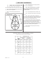
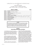
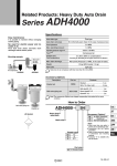
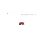
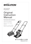
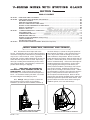
V-SERIES MIXER WITH STUFFING GLAND
SECTION B
TABLE OF CONTENTS
SECTION A
SECTION B
SECTION C
SECTION D
MIXER DATA SHEET & DRAWINGS .............................................................................................................. A-1
INITIAL INSPECTION, RECEIVING AND STORAGE ..................................................................................... B-1
MOUNTING THE DRIVE ............................................................................................................................... B-2
INSTALLING THE MIXER IMPELLER ............................................................................................................... B-3
MOTOR CONNECTIONS & LUBRICATION ................................................................................................. B-4
STUFFING GLAND PREPERATION & LUBRICATION .................................................................................... B-5
START UP & OPERATION ............................................................................................................................. B-6
START-UP CHECK LIST .................................................................................................................................. B-7
V-SERIES MAINTENANCE & LUBRICATION ............................................................................................... C-1
SHAFT RETRACTION ................................................................................................................................... C-2
OUTER BEARING REMOVAL ...................................................................................................................... C-3
INNER BEARING REMOVAL ....................................................................................................................... C-4
STUFFING GLAND MAINTENANCE (Repacking) ..................................................................................... C-5
V-BELT MAINTENANCE .............................................................................................................................. C-6
TROUBLE SHOOTING GUIDE ...................................................................................................................... C-9
MISCELLANEOUS DETAILS & INSTRUCTIONS (when required) .....................................................................
INITIAL INSPECTION, RECEIVING AND STORAGE
has been delayed, c) there are long idle periods of
time between operating cycles, store the mixer in a
clean, dry location, with circulating air, free from
wide variations in temperature. Electric motors are
easily damaged by moisture. Store the entire unit off
the floor, covered with plastic, and use desiccants to
reduce moisture buildup. If the motor shows signs of
moisture absorption before start-up, dry the motor
out by applying 10% voltage on two leads ( if in
doubt, measure resistance in windings, one to three
meg-ohms is normal). Relubricate motor before
start-up when in storage six months or more. V-Belts
are best stored by removing them from the sheaves.
Spray a metal protectant on the sheaves or any
other unprotected mild steel part. Remove all the
metal protectant before reinstalling belts. Mixer shaft
bearings require extra protection when stored. Add
grease until it shows at the seals, rotate bearings to
distribute grease, and cover the bearings.
B1.1 This mixer has been inspected at the
factory. Immediately upon receipt of the equipment
check the crating and contents for any damage that
may have occurred in transit. Check against the
packing slip and the certified drawings in section A to
make sure that all parts were received. Report any
damage or missing items immediately to the carrier
and to Sharpe Mixers. Keep shipping containers for
possible future storage or shipping.
B1.2
WHEN LIFTING THE EQUIPMENT USE
NON-METALLIC SLINGS TIGHTENED AROUND THE
MIXER HOUSING. Verify all loads are balanced
before lifting. Do not stand underneath suspended
loads. Do not lift the mixer by the shaft. Do not lift
the mixer using the motor lifting lug alone.
B1.3 Storage: Storage is when a) mixer has
been delivered to the job site and is awaiting
installation, b) mixer has been installed, but start up
LIFT MIXER USING SLINGERS TIGHTENED
AROUND THE MIXER HOUSING
BS - 7441 - 1 - 2000
DO NOT LIFT THE MIXER BY THE SHAFT
B-1
MOUNTING THE DRIVE
B2.3 Tie Rod supports need to be positioned
on each side of mixer at 45° above centerline and
45° from mixer centerline and securly attached to the
tank. After installing the flange mounting bolts
tighten the tie rods until the weight of the mixer has
been transfered equally between the nozzle and the
tie rods. See figure B2.2 for mounting details.
B2.1 Mounting structure must be stable and
strong enough to handle torque, bending moment,
and weight shown on assembly drawings. The
structure must not flex or vibrate when the mixer is in
operation. If mounting to an unstable support, mixer
loads may cause damage to the equipment, tank, or
other hazards.
Always use gaskets between flange faces
before bolting the mixer to the nozzle for proper
sealing. See figure B2.0 for mounting details.
B2.4 Pier supports need to be built under the
base of the V-Series housing. After installing the
flange mounting bolts, shim the pier until the weight
of the mixer has been transferred equally between
the pier and the nozzle. See the assembly drawing in
Section A for stud location. See figure B2.3 for
mounting details
B2.2 Pipe leg supports are normally supplied
on V-Series mixers. These aid in the support of the
mixer and need to be attached securely. Pipe legs
and bases (by others) must be cut to lenght and
threaded to match the pipe leg supports. After
installing the flange mounting bolts tighten the pipe
leg supports until the weight of the mixer has been
transfered equally between the nozzle and the pipe
legs. The specific size and location of the pipe legs
are called out on assembly drawing in Section A. See
Figure B2.1 for mounting details. (The pipe leg
supports may ship in a separate box from the drive
and may require assembly to the drive during
installation).
6"
TANK CENTERLINE
AFT AND
MIXER SH
G
ENTERLIN
NOZZLE C
7°
PLAN VIEW
FIGURE B2.0
D
D/2 + 6"
Min
PIPE LEG SUPPORTS
FIGURE B2.1
45°
D
D/2 + 6"
Min
TIE ROD SUPPORTS
FIGURE B2.2
D
Shim
D/2 + 6"
Min
PIER SUPPORT
FIGURE B2.3
B-2
BS - 7441 - 2 - 2000
INSTALLING THE MIXER IMPELLER
WARNING: Always lockout power before
installing or removing impeller.
B3.3 Split Hub Impellers: See figure B3.2.
Align key and clamp split hub impeller to shaft. Be
sure to maintain equal 1/4" gaps between hubs to
insure correct blade alignment and vibration free
operation. Tighten split hub impeller bolts to the
following torque ratings in table below. If impellers
where shipped with shims, discard prior to assembly,
do not use to assemble on mixer shaft.
B3.1 Refer to mixer assembly and impeller
detail drawings in the front of the manual for proper
impeller rotation, positioning, and placement.
B3.2 1-Piece Impellers: See figure B3.1. Slide
the impeller on the shaft facing the correct way
(according to the assembly drawings). For impellers
with keys, tighten the setscrew securely over the key.
Do not hammer parts in place. If keys do not fit, grind
to size.
Bolt Torque Ratings (split impeller bolts only)
1/2" bolt @ 29 ft.-lbs.
5/8" bolt @ 54 ft.-lbs.
3/4" bolt @ 96 ft.-lbs.
7/8" bolt @ 150 ft.-lbs
1/4" GAP
1- PIECE HYFLO II
SPLIT HYFLO II
FIGURE B3.1
FIGURE B3.2
MOTOR CONNECTIONS & LUBRICATION
B4.5 WARNING: Ground the mixer motor
properly to avoid serious injury to personnel. Grounding needs to be in accordance with the National
Electrical Code and consistent with local building
codes.
B4.1 WARNING: High voltage and rotating
parts can cause serious or fatal injury. Electric
machinery can be hazardous. Installation, operation,
and maintenance of electric machinery should be
performed by qualified personnel. Familiarity with
NEMA safety standards, National Electrical Code and
local building codes are required.
B4.6 Electric AC Variable Speed: Electric
motors using an AC variable frequency controller
must be wired following the instructions supplied with
the controller. See data sheet and assembly
drawings for possible RPM lockout ranges. Operate
only at speeds outlined on those sheets. Damage to
equipment or serious injury to personnel can result, If
speed limitations are not followed.
B4.2 Wiring: Starting and overload control
devices must be matched to motor rating. Follow
control manufacturer's instructions for proper connections and installation.
B4.3 Electrical connections must conform to
National Electrical code and all local regulations.
Line voltage and wire capacity must match motor
rating stamped on motor nameplate.
B4.7 Motor lubrication: Electric motor bearings
are often sealed and need no relubrication. When
zirc fittings are present, relubricate with a No. 2
consistency lithium soap base and petroleum compound. Relubricate every 6 months to 1 year
depending on usage. Open and clean drains. Add
grease until new grease is forced out drain. Remove
excess grease and replace input plugs. Run motor
one half hour before replacing drain plugs.
B4.4 Electric motors - 3 phase: Motors
requiring 3 phase power must be wired according to
the wiring diagrams on the motor. Rotation of the
impeller must be according to the assembly drawing
and data sheet. Interchange lines if necessary for
proper rotation.
BS - 7441 - 3 - 2000
B-3
STUFFING GLAND PREPARATION & LUBRICATION
B5.1
DO NOT OVER TIGHTEN THE PACKING!
Stuffing glands are designed to control leakage, not
to prevent it. During start-up permit generous initial
leakage. Gradually take up gland nuts 1/6 turn (1
flat in hex nuts) at a time. Watch temperature.
NEVER PERMIT HEAT TO DEVELOP - BACK OFF GLAND
NUTS IF IT DOES. As leakage levels off on side entry
units, tighten at 15 minute intervals until leakage is
controlled without developing heat. On a 2" dia. side
entry shaft, permit 10 to 30 drops per minute, a 4"
shaft would be allowed to leak twice as much, etc.
daily. Weight loaded lubricators or other self lubricating devices are available from Sharpe Mixers to aid in
seal lubrication. When seal flushing is required
remove the 1/8" zirc fitting and replace it with flushing
lines (supplied by others). Flush with clean liquid
having lubricating properties.
B5.4 5-RING GLAND WITH THROTTLE BUSHING:
A throttle bushing requires a constant flow of flush
water during operation. One side of the gland is
tapped for a 1/4" N.P.T. flush line, the other side has a
fitting with a pin that holds the throttle in postion.
(See figure C5.2) Install a rotometer (available from
Sharpe Mixers) and adjust for 0.1-0.2 gal/min for 2"
shaft to 0.3/0.5 gal/min for 5" shaft.
B5.3 7-RING STUFFING GLAND WTH LANTERN
RING LUBRICATION: Stuffing glands come with a zirc
fitting on the side of the seal housing and should be
greased regularly. When mixing abrasive nonlubricated liquids the zirc fitting should be greased
FOR REPACKING THE GLAND SEE SECTION -C5-
START UP & OPERATION
B6.1 Before starting up, visually inspect the
mixer. Verify that the mixer components matches the
certified drawings in the front of the manual.
B6.10 Extended operation of the mixer when
liquid level is at or near the impeller is not
recommended. Excessive loading and vibration will
occur.
B6.2 Check all mounting and impeller bolts.
Verify that they are installed and have been
tightened.
B6.11 When mixing products of dissimilar
viscosities and/or specific gravities the lighter or less
viscous material should be introduced first. Gradually
add the heavier material or powders into the center
of the tank while the agitator is running. Never dump
large amounts of powder or solids into the mixing
tank. This may create clotting or “sanding in” of
impeller and cause damage to the equipment.
B6.3 The V-Belts have been installed at the
factory. They may have shifted during shipment.
Remove the Belt Guard, Item #376 Check belt
installation and alignment, Refer to Section C6 for
proper installation.
B6.4 Rotate mixer shaft by hand using the
driven sheave, Item # 373. Check for binding, shaft
straightness and assure that the impeller is free of any
obstructions in the tank. Install Belt Guard when
done.
B6.12 Keep motors free from oil, dust, dirt,
water, and chemicals. Keep air intakes and outlets
free from foreign material. Electric motors supplied,
although designed for outdoor use, may be damaged due to weather. A rain hood or other protection may be necessary to prolong motor life. Consult
factory for recommendations.
B6.5 Check the stuffing box, Item # 400, for
adjustment & lubrication. See Stuffing Gland
Preparation & Lubrication section B5 for installation
and start-up procedures.
B6.13 Regular maintenance is the best assurance of trouble free, long life mixer operation.
Inspect and relubricate at regular intervals. Frequency and thoroughness depends on operation,
nature of service, and environment.
B6.6 Test line resistance to check for possible
moisture in the motor. Refer to Paragraph B4.3 Do
not apply power if any resistance exceeds one to
three meg-ohms.
B6.14 In the event of a break down within the
warranty period, Sharpe Mixers must be notified
within 15 days if it is intended that the warranty is to
cover the problem. When requesting spare/replacement parts anytime, have serial number and model
number off mixer nameplate readily available. Do
not disassemble components or otherwise modify
equipment without prior authorization from Sharpe
Mixers or warranty will be voided. Sharpe Mixers will
not accept back charges for any repair work that
has not been previously authorized.
B6.7 Verify that the wiring is installed,
grounded and insulated. Check Motor wiring against
the diagram supplied with the motor.
B6.8 Prior and During start up complete the
start-up check list, section B7.0
B6.9 If impeller is buried in solids prior to
starting mixer, solids must be dispersed. This may be
achieved with an air hose, a recirculating pump, or a
large stirring stick if necessary (depends on tank size).
B-4
BS - 7441 - 4 - 2000
START-UP CHECK LIST
WARNING: Lockout / Tagout power before
servicing or start-up. High voltage and rotating
parts can cause serious or fatal injury.
B7.0
CAUTION: DO NOT START MIXER WITH IMPELLER
BURIED IN SOLIDS OR WITH LIQUID SOLUTION SOLIDIFIED. DAMAGE WILL OCCUR.
Start-Up Checklist
Prior and during start-up please check that the following things have been done:
a.
Manual has been read and followed............................................................................
b.
All Certified drawings have been reviewed..................................................................
c.
Outboard support has been shimmed and leveled so that the
mixer flange is parallel to tank flange.............................................................................
d.
Driven belts have been aligned and tensioned............................................................
e.
All guards have been installed.......................................................................................
f.
Bearings have been greased and setscrews tightened..............................................
g.
Impeller has been installed correctly (see certified drawings)....................................
h.
All assembly bolts have been checked and tightened...............................................
i.
High Pressure Stuffing box Zirc fitting greased................................................................
j.
Wiring correctly installed, grounded and insulated......................................................
k.
Motor checked for moisture absorption
Resistance (less than 3 meg-ohms):..................................................................
l.
Check shaft rotation against certified drawings...........................................................
m.
Impeller immersed in liquid before operation................................................................
n.
Correct voltage/amperage @ start-up:.........................................................................
Motor nameplate F.L.A.:
F.L.A. measured with ampmeter (each lead)
Actual line voltage measured (each lead)
o.
Proper seal run-in time allowed (see Sec B5 for break in detail)...............................
p.
Excessive vibration at mixer support or flange?............................................................
q.
Excessive shaft runnout out seal? Measure:
r.
Mixer operating to design specifications.......................................................................
INSPECTOR
BS - 7441 - 5 - 2000
.................
DATE
B-5
SECTION C
V - SERIES MAINTENANCE AND LUBRICATION
C1.1
V-SERIES mixer shaft bearings are
greased at the factory with a NLGI Grade No. 2
Lithium 12-hydroxystearate grease suitable for roller
bearings in normal operating conditions. If mixer has
been idle or stored for a while add fresh grease
before running.
C1.2 Abnormal bearing temperature may
indicate faulty lubrication. Normal temperature
ranges from "cool to touch" to "too hot to touch for
more than a few seconds", depending on bearing
size, speed, and ambient conditions. Unusually high
temperatures with excessive leakage of grease
indicates too much grease. High temperature
coupled with no grease leakage at the seals indicates too little grease, especially if the bearing seems
noisy. Normal temperatures and small bead of
grease at the seals indicates proper lubrication.
C1.3 Lubrication of mixer shaft bearings is
required every 5 to 12 weeks, depending on usage.
V-SERIES PART DETAIL
372
100
374
123
130
452
131
371
453
132
451
551
320
454
552
302
750
675
373
674
600
375
376
459 463
450
307
378
377
ITEM
100
103
123
130
131
132
•300
•302
306
307
308
314
320
•371
372
373
374
375
376
377
378
379
380
381
478
314
672
300
308
556
PART NAME
Motor
Motor bushing key
Motor mounting bolts, nuts, & washers
Motor mounting plate
Motor sheave tension studs (4)
Motor sheave tension nuts (16)
Inner bearing
Outer bearing
Bearing mounting bolts & washers
Bearing snap ring
Bearing jacking bolts (2)
Bearing setscrews
Bearing removal plate
V-Belts
Motor sheave
Driven sheave
Motor bushing
Driven bushing
Belt guard
Belt guard base
Belt guard bolts, nuts, & washers
Belt guard base mounting nuts & washers (8)
382
450
•451
452
453
•454
459
458
463
551
552
555
556
559
•600
672
673
674
•675
676
730
731
750
Motor sheave busing bolts & washers (3)
Driven sheave busing bolts & washers (3)
• = Recommended spare part
BS - 7441 - 1 - 2000
C-1
Driven bushing key
High Pressure Stuffing box
Seal packing rings
Follower plate
Follower ring
Lantern ring/Throttle bushing
Seal Zirc fitting
Slinger
Throttle locator
Mixer pedestal
Mounting flange
Tie rod assembly (not shown)
Pipe leg supports (Shown)
Mounting flange bolts & washers (by others)
Mixer shaft
Retraction collar
Support collar bolts
Seal collar
Seal collar gasket
Seal collar setscrews (3)
Impeller key
Impeller setscrew
Impeller
FIGURE C1.1
SHAFT RETRACTION
C2.1 The shaft retraction feature is normally
provided for larger side entry mixers. This device
allows seal replacement without draining the tank.
The following procedure outlines the operation of
"shaft retraction". Refer to Figures C1.1 and C2.3 for
parts identification.
C2.2
C2.6 To return shaft to its original position,
loosen Jacking bolts 308 , and tighten bearing
mounting bolts. This will bring bearing shaft back to its
original position. Tighten all bearing setscrews.
C2.7 The mixer is now ready for service. See
Section B5 for Stuffing Gland Preperation &
Lubrication and see Section B6 for Start-up and
Operation.
Disconnect the power from the mixer.
C2.3 Loosen the mixer shaft bearing setscrews
in the outer bearing, 302 . Loosen the inner bearing
mounting bolts approximately 1/4". Do not remove
the bearing or snap ring at this time.
552
675
674
C2.4 Tighten the two Jacking bolts, 308 in the
inner bearing plate so the bearing and shaft move
out approximately 1/16" to 1/8" until further retraction becomes difficult. This tightness indicates that
the seal collar, 674 and gasket, 675 have
pressed tightly against the tank side of the mounting
flange and a proper static seal has been attained.
See figure C2.1 for retraction detail.
307
300
RETRACT SHAFT UNTIL
SEAL COLLAR AND
GASKET PRESS TIGHT
TO THE FLANGE FACE.
2.5 The mixer is now ready to have the seal
serviced. See Section C5.0 for procedures.
1/16" MIN
308
FIGURE C2.1
OUTER BEARING REMOVAL
C3.4 Clean shaft of dust, dirt, and debris
before removing bearing from shaft. Use of a light oil
may aid in bearing removal from shaft.
C3.1 This procedure is to remove the outer
bearing, 302 , from the mixer. If the inner bearing,
300 , is also to be removed and serviced, see "Bearing removal with full tank", Section C4.1. Note: shaft
retraction is not required to remove outer bearing.
C3.2
C3.5 Loosen bearing setscrews. Remove the
mounting bolts from the bearing removal plate, 320 .
Slide the outer bearing 302 with plate 320 off end
of shaft ( two bolts threaded in the tapped holes in
the removal plate can be used as jacking screws if
the bearing is stuck ).
Disconnect the power from the mixer.
C3.3 Remove the belt guard, 376 , belts, 371
bushing, 375 , and large sheave, 373 .
377
376
374
371
372
373
320
375
302
FIGURE C2.3
C-2
BS - 7441 - 2 - 2000
INNER BEARING REMOVAL ( WITH FULL TANK )
C4.1 This procedure is to remove both mixer
shaft bearings from the mixer while mounted to a full
tank. See figure C4.1.
C4.9 Loosen the inner bearing setscrews, 314
remove the snap ring, 307 . Be sure shaft is clean
before moving bearing. Use of light oil may aid in
bearing removal from shaft.
C4.4 Follow the Side Entry Retraction in
section C2.1.
C4.10 Remove the inner bearing mounting
bolts and slide the bearing off the shaft. Tighten
jacking screws, 308 to aid in removal.
C4.5 Remove split support collar, 670 , from
shaft. Clean bore of collar.
CAUTION: Be sure to remove bearings slowly
and straight out so as not to disrupt the static seal at
the mounting flange.
C4.6 Move the High Pressure Stuffing Box
follower plate 452 , and the follower ring, 453
towards the inner bearing.
C4.11 Inspect bearings for wear and damage, replace when necessary.
C4.7 Reinstall the support collar, 670 in place
of the removed seal components with the register
fitting inside the packing gland. Tighten collar onto
shaft while holding the collar tightly against the
gland. This will hold the shaft in place while the
bearings are removed.
C4.12 To reassemble, reverse procedure.
Clean shaft for bearing installation. Inner bearing,
307 ,must be brought back into it's original position
prior to start-up. Tighten all bolts, setscrews and
replace the snap ring before operating mixer.
C4.8 Remove the outer bearing using the
procedure described in Section C3.1
308
302
307
314
307
478
452
453
670
FIGURE C4.1
BS - 7441 - 3 - 2000
C-3
STUFFING GLAND MAINTENANCE
lantern ring must be in the proper position or damage
may occur.
C5.1 REPACKING THE GLAND: Packing tools:
Special flexible corkscrew tools specifically designed
for packing make seal servicing an easy task (see
Figure C5.1). Various size tools are available from
Sharpe Mixers.
C5.6 Install rings over the shaft by twisting
open as shown in Figure C5.4. This is especially
important for metallic rings. NEVER open rings with
hinge like action.
C5.2 Once power has been disconnected
and shaft retraction has occurred (see Section C2.1),
remove the old rings. If a lantern ring is present, there
are (4) slots cut into the outside edges. This helps the
packing tools "grab" the lantern ring for removal. Use
caution when removing old rings. Do not score shaft.
Before installing the new rings, be sure that the new
packing is of the proper type and size for your
application (see Data Sheet and sales drawings in
front of manual for seal size and configuration).
C5.7 Insert rings one at a time with joints
staggered 90° apart. Seat each ring individually,
compressing in place with a tamping tool or by using
a split hollow cylinder. Turn mixer shaft occasionally
to assist seating. Unless each ring is properly seated,
the gland follower will not be able to tighten the
packing set, as it will leave the front rings (nearest
the follower ring) too tight in the stuffing box. Bear in
mind that, except for abrasives, 70% of the wear
normally takes place on the two packing rings
nearest the follower ring. Proper seating and lubrication spreads the wear out more evenly over the entire
set of rings. Adjust follower finger tight only to begin.
After shaft has been replaced to proper running
position, See Paragraph B5.1 for seal start-up
procedures.
C5.3 If you purchase your packing rings from
other than Sharpe Mixers, you may have to cut the
rings yourself. To do this, wind the packing around a
mandrel of the same diameter as the mixer shaft for
the desired number of rings (see Figure C5.3). Cut
rings by making a straight cut along the mandrel as
shown. When removing rings from mandrel, slip them
off without opening the rings. This is especially
important for metallic types. Do not open with a
hinge-like action (see Figure C5.4).
C5.4 Check condition of stuffing box and the
shaft in the seal area. If either are rough or scored,
they need to be reworked or replaced. Without
repairing the damaged areas, gland take-up will
result in distortion of the rings and over compression
of the packing on the mixer shaft. The packing will
not seal properly and will burn out sooner, further
damaging the seal area. If wearing in the seal area
is evident contact the factory for recommendations.
Throttle
locator pin
1/4" N.P.T.
Water flush
Throttle
bushing
C5.5 Coat new rings with a lubricant to assist
with installation and break-in (Do not use on food
grade packings, liquid oxygen service, nitric acid, or
any other non-compatible application). Check
position of all gland parts against the applicable seal
drawing. Replace all worn or damaged parts. The
STUFFINGBOX WITH THROTTLE BUSHING
FIGURE C5.2
452
450
453
451
454
459
FIGURE C5.3
STANDARD 7-RING STUFFING BOX
FIGURE C5.1
FIGURE C5.4
C-4
BS - 7441 - 4 - 2000
V-BELT DRIVE MAINTENANCE
C6.1
C6.5 Keep belts free from foreign material
which may cause slippage.
GENERAL RULES FOR TENSIONING BELTS:
C6.2 Ideal tension is the lowest tension at
which the belt will not slip under peak load condition.
C6.6 Make v-belt inspection on a periodic
basis. Tension when slipping. Never apply belt
dressing as this will damage the belt and cause
premature failure.
C6.3 Check tension frequently during the first
24 - 48 hours of run in operation.
C6.4 Over tensioning shortens belt and
bearing life.
C6.7 For tensioning the belts, use Table C6.2.
C6.8
Measure the span length 'K'. (See figure
C6.1)
BELT DEFLECTION
1/64" PER INCH OF SPAN
C6.9 At the center of span 'K' apply force.
Tension the belts until this force deflects the belt 1/64"
for every inch of span length. Example: The deflection of a 48" span would be 48/64" or 3/4".
FORCE
SPAN 'K'
C6.10 Tension belts by raising or lowering the
motor using the four large motor stud adjustment nuts
directly under the motor mounting plate. Note:
measure the distance between the motor plate and
the top of the housing. Maintain equal dimensions at
each corner to maintain proper alignment.
C6.11 Replace belt guard prior to running
mixer under power.
Figure c6.1
Center Distance Allowance for Narrow Belt Installation and Take-Up
(contact factory for values not shown in this table)
Belt Deflection Force (lbs.)
Cross
Section
3VX
5V,
5VX
Dyna-V Uncogged
Polyband
Dyna-V COG
Cogged Polyband
Smallest
Sheave
Diamete
r Range
Normal
New Belt
Normal
New Belt
2.2 - 2.4
-
-
3.3
4.9
2.65 3.65
3.6
5.1
4.2
6.2
4.12 6.90
4.9
7.3
5.3
7.9
4.4 - 6.7
-
-
10.2
15.2
7.1 - 10.9
12.7
18.9
14.8
22.1
11.8 16.0
15.5
23.4
17.1
25.5
12.5 17.0
33.0
49.3
-
-
18.0 22.4
39.6
59.2
8V
BS - 7441 - 5 - 2000
C-5
Table
C6.2 -
Sheave installation
C7.1 QD bushings can be installed in either
position, bushing flange toward motor or away from
motor. Before final installation, determine best
position so as no mechanical interference will occur
with belt guard installed. In either case, sheave
mounting bolts will be installed from the outside,
through the holes of the outer piece and into the
threaded holes of the part next to the motor (either
bushing flange or sheave hub). Be sure keys are in
place to assist in torque transmission.
C7.2 Sheave alignment: Adjustment needs
to be checked to maximize life of the sheaves and
belts (see Figure C7.1). This is done by placing a
straight edge across the sheave faces so that it
touches all four points of contact. Ordinarily, a
misalignment of 1/2° (1/8" per foot) will shorten belt
and/or sheave life. Improper sheave alignment
produces uneven wear on one side of the belt,
causes belts to roll over in the sheave, or throws all
the load on one side of the belt, stretching or breaking the cords on that side.
Correct
alignment
linear
offset
Angular
offset
Figure C7.1
Belt installation
so applied will ride higher in the sheave, travel faster,
and operate at a much higher tension than the used
belts. The cord center may be damaged, allowing
the new belt to elongate. Shortly after this occurs, it
will cease to accept its share of the load, leaving the
drive under belted. Thus the new belt is wasted. Belts
are worn in cross-section and stretched. A new belt
so applied will ride higher in the sheave, travel faster,
and operate at a much higher tension than the used
belts. The cord center may be damaged, allowing
the new belt to elongate. Shortly after this occurs, it
will cease to accept its share of the load, leaving the
drive under belted. Thus the new belt is wasted. Belts
of different manufacturers should not be mixed for
the same reasons.
C8.1 Before a new set of belts are installed check condition of sheaves. Dirty or rusty sheaves
impair the drives efficiency and abrade the belts,
which result in premature failure.
C8.2 Worn sheaves shorten belt life as much
as 50%. If the grooves are worn to where the belt
bottoms, slippage may result and burn the belts. If
side walls are "dished out", the bottom shoulder ruins
the belt prematurely by wearing off the bottom
corners.
C8.3
Installation and take-up allowance:
Find the center distance and belt size on the Certified
drawing in front of this manual. Follow the belt
tentioning in Section C6.
C8.5 To place the belts on the sheaves,
shorten the center distance of the sheaves until the
belts can be installed without forcing. Forcing belts
on sheave can cause internal injury to the belts.
C8.4 Never employ a used belt as a
replacement for a unit of a set. Used belts, normally,
are worn in cross-section and stretched. A new belt
C-6
BS - 7441 - 6 - 2000
TROUBLE SHOOTING GUIDE
C9.0
PROBLEM
•Shaft will not fit into drive
•Mixer will not start
POSSIBLE CAUSE
SOLUTION
•Bearing Set screws extend into bore
•Shaft over size
(proper dia. 0.001" - 0.002"
under nominal dia.
•Damaged shaft
•Oversize key
•Loosen set screws
•Measure and consult factory
•Incorrect wiring
•Loose connections
•Blown fuse
•Incorrect voltage
•Impeller interference
•Water damage to
motor
•Wrong size heaters in
starter
•Mixer will not
reach correct
speed
•Overload of motor
•Loose drive coupling bolts
•Consult factory
•Grind key to fit
•Check wiring diagram
and wire correctly
•Check and tighten
connections
•Replace fuse
•Wire for correct voltage
•Free all debris for rotation
•Service or replace motor
(consult factory)
•Replace heaters
•Check amperage against
nameplate data
•Check coupling bolt tension
(coupling and/or shaft
maybe damaged if
mixer has been run with
slipping coupling)
•See “Mixer will not start”
•Motor runs hot /
•Amperage overload
•Low or high voltage
•Product too viscous
•Restricted ventilation
•Frequent starting and
stopping
•Unbalanced voltage
between phases
•Incorrect rotation
•Product too viscous
•Impeller installed backwards
•Impeller too close to tank floor
•Lack of/improper lubricant
•Improper output speed
•Build up of sediment on tank bottom
•Undersized heaters
CAUTION: DO NOT MODIFY MIXER WITHOUT PRIOR
AUTHORIZATION FROM SHARPE MIXERS OR
WARRANTY WILL BE VOID. (DISCARD WHEN MIXER
IS OUT OF WARRANTY PERIOD.)
BS - 7441 - 7 - 2000
C-7
•Wire for correct voltage
•Check viscosity and specific
gravity of product
(consult factory)
•Clear vents
•Check with factory - a special
motor may be required
•Consult electrician
•Change motor leads per
nameplate instructions
•Check viscosity and specific
gravity - consult factory
•Check against assembly drawings correct if required
•raise impeller
•Add or change lubricant
(see Section C)
•Confirm speed - consult factory
•Clean or irrigate sediment
•Replace with correct heaters
PROBLEM
•Noisy
POSSIBLE CAUSE
•Mechanical interference
between belts
& belt guard
• Belt slippage
• Misaligned sheaves
• Sheave wobble
SOLUTION
• Check belts for proper tension
• Retension drive
• Align sheaves
• Tighten setscrews; check alignment
•Bearing failure
•Belts over tensioned
•Sheaves too small
• Sheaves too far out
on shaft
• Misaligned sheaves/motor
•See all items under “Noisy”
• Tension properly
• Consult factory
• Place sheaves as close as possible
to bearings
• Align
• Belt slippage
• Overload of drive
• Worn sheaves
• Excessive oil, dust, grease
• Improper companion
sheave size
• Undersized P.D. (belt
riding on bottom
of sheave
• Consult factory
• Replace sheaves
• Provide better shield
• Consult factory
• Misaligned sheaves
• Loose motor supports
• Realign sheaves - remove "bends"
• Replace undersized screws or
broken base
• Replace sheaves
• Rapid belt wear
• Damaged or worn
grooves/sheaves
• Excessive temperatures
• Mechanical interference
• Overloaded drive
• Broken belt cords
(excessive spring
tension)
• Dirt/grit entering drive
• Sheaves too small
• Oil or grease on
belts or sheaves
• Tensile members
damaged through
improper installation
•Vibration
• Sheave wobble
• pulleys/sheaves out of
balance
• Pulsating loads belt hop
and skip
• Excessive pulley spring
tension
C-8
• 1/32" min. belt clearance when belt
at pulley's min. pitch dia.
• Remove source - ventilate belt guard
• Remove interference - move pulley
• Consult factory
• Reduce pulley HP rating/spring tension
• Air ventilate belt guard
• Consult factory
• Remove source of oil or grease - clean
belts/grooves with alcohol
moistened cloth
• Replace with new matched set
install properly
• Replace distorted/eccentric sheave/
worn QD bushing
• Determine cause
- consult factory
• Belts side surfaces glazed replace; remove oil from
pulley's flange surfaces
• Install lighter HP rated pulley
-consult factory
BS - 7441 - 8 - 2000
PROBLEM
•Seal leakage
POSSIBLE CAUSE
•Proper amount of leakage
•Worn packing
•Scored shaft
•Insufficient/incorrect lubrication
•Excessive heat in gland
•Split in packing rings not offset
•Charred / glazed packing
•Solids in seal gland
•Scored shaft
•Insufficient/incorrect lubrication
•Excessive heat
•Excessive shaft runout
SOLUTION
•See Section B5
•Replace packing
•Replace shaft and packing
check stuffing box also
for possible scoring
•Lubricate properly
(see Paragraph B5)
check parts for scoring
- replace if necessary
•Back off gland nuts
(replace packing if
necessary) check parts for
scoring - replace if
necessary
•Remove packing, reinstall
offset (see Section B5)
•Improper run-in, replace packing
(see Section B5)
•Flush properly
(see Section B5)
•Replace shaft and seal;
lubricate/flush seal
•Lubricate properly
(see Section B5)
•Lubricate properly or consult
factory, a special packing
may be required
•See "Shaft vibration"
ALWAYS REFERENCE THE MIXER SERIAL NUMBER
WHEN PLACING ORDER OR MAKING PARTS
INQUIRY. THIS SERIAL NUMBER IS LOCATED ON
THE SHARPE MIXER NAMEPLATE & ON THE FRONT
COVER OF THE SERVICE MANUAL.
CAUTION: DO NOT MODIFY MIXER WITHOUT
PRIOR AUTHORIZATION FROM SHARPE MIXERS
OR WARRANTY WILL BE VOIDED. (DISREGARD
WHEN MIXER IS OUT OF WARRANTY PERIOD.)
RECOMMENDED SPARE PARTS
C10.0 Recommended spare parts are different for individual needs. The main factor affecting which
parts should be kept on the shelf of the user is downtime (allowable time period the mixer can be out of
service).
Note: Impellers, although not normally wearing parts, may be damaged and require repair/replacement.
These parts are long delivery items and should be considered if extended down time is unacceptable. For any
downtime, all wearing parts are normally recommended spares. These include: bearings, lantern rings, packing, gaskets, V-belts, wear sleeves and shafts.
Standard shipment
Recommended parts to stock for repair due to long delivery
8 to 10 weeks
- Complete mixer sizes V40 and above (Consult factory to expedite)
6 to 8 weeks
- Complete mixer sizes V30 and below (Consult factory to expedite)
5 weeks
- Hardened shafts, special motors (call for quote)
3 to 4 weeks
- Machined parts, wear sleeves, impellers, stuffing gland throttles/bushings,
mixer shafts, belt guards
2 weeks
- Standard motors
3 to 5 days
- Stock motors, gland packing, V-belts, bearings, sheaves, bushing
Expedited Services - Consult factory for price and delivery
BS - 7441 - 9 - 2000
C-9
End of Section -C-