1
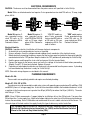
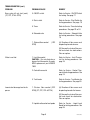
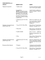
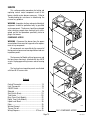
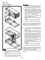
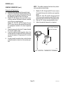
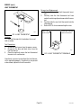
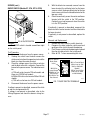
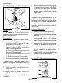
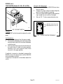
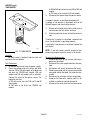
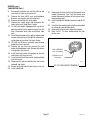
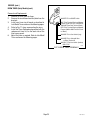
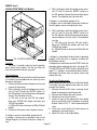
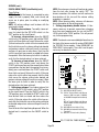
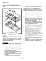
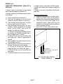
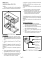
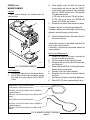
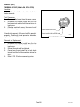
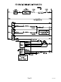
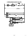
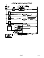
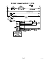
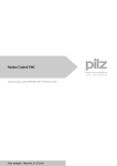
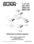
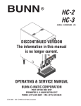
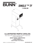
BUNN
®
S,SA
ST,STA
STF,STFA
OPERATING & SERVICE MANUAL
BUNN-O-MATIC CORPORATION
POST OFFICE BOX 3227
SPRINGFIELD, ILLINOIS 62708-3227
PHONE: (217) 529-6601 FAX: (217) 529-6644
29251.0000G
04/01 ©1998 Bunn-O-Matic Corporation
www.bunnomatic.com
WARRANTY
Bunn-O-Matic Corp. (“Bunn”) warrants the equipment manufactured by it to be commercially free from defects
in material and workmanship existing at the time of manufacture and appearing within one year from the date of
installation. In addition:
1.) Bunn warrants electronic circuit and/or control boards to be commercially free from defects in material and
workmanship for three years from the date of installation.
2.) Bunn warrants the compressor on refrigeration equipment to be commercially free from defects in material
and workmanship for two years from the date of installation.
3.) Bunn warrants that the grinding burrs on coffee grinding equipment will grind coffee to meet original factory
screen sieve analysis for three years from date of installation or for 30,000 pounds of coffee, whichever comes first.
This warranty does not apply to any equipment, component or part that was not manufactured by Bunn or that,
in Bunn’s judgement, has been affected by misuse, neglect, alteration, improper installation or operation, improper
maintenance or repair, damage or casualty.
THE FOREGOING WARRANTY IS EXCLUSIVE AND IS IN LIEU OF ANY OTHER WARRANTY, WRITTEN OR
ORAL, EXPRESS OR IMPLIED, INCLUDING, BUT NOT LIMITED TO, ANY IMPLIED WARRANTY OF EITHER
MERCHANTABILITY OR FITNESS FOR A PARTICULAR PURPOSE. The agents, dealers or employees of Bunn are
not authorized to make modifications to this warranty or to make additional warranties that are binding on Bunn.
Accordingly, statements by such individuals, whether oral or written, do not constitute warranties and should not
be relied upon.
The Buyer shall give Bunn prompt notice of any claim to be made under this warranty by telephone at (217)
529-6601 or by writing to Post Office Box 3227, Springfield, Illinois, 62708-3227. If requested by Bunn, the Buyer
shall ship the defective equipment prepaid to an authorized Bunn service location. If Bunn determines, in its sole
discretion, that the equipment does not conform to the warranty, Bunn shall repair the equipment with no charge
for parts during the warranty period and no charge for labor by a Bunn Authorized Service Representative during
the warranty period. If Bunn determines that repair is not feasible, Bunn shall, at its sole option, replace the
equipment or refund the purchase price for the equipment.
THE BUYER’S REMEDY AGAINST BUNN FOR THE BREACH OF ANY OBLIGATION ARISING OUT OF THE SALE
OF THIS EQUIPMENT, WHETHER DERIVED FROM WARRANTY OR OTHERWISE, SHALL BE LIMITED, AS
SPECIFIED HEREIN, TO REPAIR OR, AT BUNN’S SOLE OPTION, REPLACEMENT OR REFUND.
In no event shall Bunn be liable for any other damage or loss, including, but not limited to, lost profits, lost sales,
loss of use of equipment, claims of Buyer’s customers, cost of capital, cost of down time, cost of substitute
equipment, facilities or services, or any other special, incidental or consequential damages.
#00831.0000
USER NOTICES
Page 2
#00658.0000
29251 042301
USER NOTICES (Continued)
#00882.0000
#00656.0000
#02763.0000
#02765.0000
#02769.0000
Page 3
29251 101598
ELECTRICAL REQUIREMENTS
CAUTION - The brewer must be disconnected from the power source until specified in Initial Set-Up.
Model 15 has an attached cordset and requires 2-wire grounded service rated 120 volts ac, 15 amp, single
phase, 60 Hz.
L2 RED
WHITE
NEUTRAL
L1 BLACK
WHITE
120V.A.C.
NEUTRAL
WHITE
120V A.C.
208 or
240V.A.C.
120V A.C.
NEUTRAL
L1 BLACK
100V.A.C.
L1 BLACK
P2185
Model 20 requires 2wire, grounded service
rated 120 volts ac, 20
amp, single phase, 60 Hz.
Proceed as follows:
P1841
Model 35 requires 3wire, grounded service
rated 120/208 or 120/240
volts ac, 20 amp, single
phase, 60 Hz. Proceed as
follows:
P2185
P2193
“A" & "B” models require 2-wire, grounded
service rated 200 volts ac
or 240 volts ac, 20 amp,
single phase, 50 Hz. Proceed as follows:
"SDB” model requires
2-wire, grounded service
rated 100 volts ac, 20
amp, single phase, 50 Hz.
Proceed as follows:
Electrical Hook-Up
CAUTION – Improper electrical installation will damage electronic components.
1. An electrician must provide electrical service as specified.
2. Using a voltmeter, check the voltage and color coding of each conductor at the electrical source.
3. Before electrically connecting the brewer, remove the front and rear panel and rotate the thermostat knob fully
counterclockwise to the "OFF" position. Keep this knob in the "OFF" position until performing the "Initial Set-Up"
4. Feed the power cord through the strain relief and connect it to the terminal block.
5. Connect the brewer to the power source and verify the voltage at the terminal block before proceeding.
(Models S and ST-15 have cord attached. Replace all panels.
6. If plumbing is to be hooked-up later be sure the brewer is disconnected from the power source. If plumbing
has been hooked-up, the brewer is ready for "Initial Set-Up".
NOTE: Schematic wiring diagrams are included in this manual.
PLUMBING REQUIREMENTS
Models S & SA:
These models are completely portable and require no attached plumbing.
Models ST, STA, STF & STFA
These brewers must be connected to a cold water system with operating pressure between 20 and 90 psi (138
and 620 kPa) from a 1⁄2" or larger supply line. A shut-off valve should be installed in the line before the brewer. Install
a regulator in the line when pressure is greater than 90 psi (620 kPa) to reduce it to 50 psi (345 kPa). The water
inlet fitting is 1⁄4" flare.
NOTE - Bunn-O-Matic recommends 1⁄4" copper tubing for installations of less than 25 feet and 3⁄8" for more than
25 feet from the 1⁄2" water supply line. A tight coil of copper tubing in the water line will facilitate moving the brewer
to clean the countertop. Bunn-O-Matic does not recommend the use of a saddle valve to install the brewer. The
size and shape of the hole made in the supply line by this type of device may restrict water flow.
This equipment must be installed to comply with the Basic Plumbing Code of the Building
Officials and Code Administrators International, Inc. (BOCA) and the Food Service Sanitation
Manual of the Food and Drug Administration (FDA).
Page 4
29251 011800
INITIAL SET-UP
CAUTION - The brewer must be disconnected from the power source throughout the initial set-up, except when
specified in the instructions.
1.
2.
3.
Insert an empty funnel into the funnel rails.
Place an empty dispenser under the funnel.
Remove the front or rear panel and turn the thermostat knob to the “OFF” position and connect the brewer
to the power source.
4. Fill the tank with water as directed:
4A. Models S & SA:
Pour three pitchers of tap water into the screened area on top of the brewer. Allow approximately two minutes
between pitchers for water to flow into the tank. While the third pitcher of water is entering the tank, the tank
will fill to capacity and the excess will flow from the sprayhead, out of the funnel, and into the dispenser.
4B. Models ST, STA:
Connect the brewer to the power source, place the "ON/OFF" switch in the "ON" upper position, and
momentarily press and release the start switch. Water will begin flowing into the tank. When water stops
flowing into the tank, initiate a second and a third brew cycle. During the third brew cycle the tank will fill to
its capacity and the excess will flow from the sprayhead, out of the funnel, and into the dispenser.
4C. Models STF & STFA
Brewers will fill automatically when lower ON/OFF switch is placed in the "ON" position and tank will fill to
capacity.
5. When the flow of water from the funnel stops, turn the thermostat knob to the “ON” position and wait
approximately twenty minutes for the water in the tank to heat to the proper temperature. Some water will
drip from the funnel during this time; this is due to expansion and should not occur thereafter.
6. Empty the dispenser and initiate another brew cycle as directed:
6A. Models S & SA:
Pour one pitcher of tap water into the screened area on top of the brewer.
6B. Models ST, STF, STA & STFA:
Place the "ON/OFF" switch in the "ON" upper position, and momentarily press and release the start switch.
7. Place the "ON/OFF" switch in the lower “OFF” position after water has stopped flowing from the funnel, and
let the water in the tank reheat to the proper temperature.
8. Empty the dispenser and proceed as directed:
8A. Models S & SA:
The brewer is now ready for use in accordance with the coffee brewing instructions on the next page.
8B. Models ST, STF, STA & STFA:
Place the "ON/OFF" switch in the "ON" upper position, and momentarily press and release the start switch.
Check the water volume in the dispenser after water has stopped flowing from the funnel. It should be 64
ounces.
9. If not, disconnect the brewer from the power source. On early models remove the access panel. Adjust the
timer as required (see service section). Replace the panel, connect the brewer to the power source, and allow
the water to reheat, start, and measure another brew cycle.
10. Repeat step 9 until 64 oz water volume is achieved.
11. The brewer is now ready for use in accordance with the coffee brewing instructions on the next page.
Page 5
29251 052500
OPERATING CONTROLS
Models S & SA:
These models function without operating controls.
Models ST, STF, STA & STFA:
ON/OFF SWITCH
Placing the "ON/OFF" switch in the "OFF" lower position stops brewing. Stopping a brew cycle after it has been
started will not stop the flow of water into the funnel until the tank syphons down to its proper level. Placing the
switch in the "ON" upper position supplies power to the brew station warmer and enables the brew circuit and on
Models STF and STFA refills the tank.
START SWITCH
Momentarily pressing and releasing the switch starts a brew cycle when the "ON/OFF" switch is in the "ON" upper
position.
NOTE – The "ON/OFF" switch must be in the "ON" upper position to initiate and complete a brew cycle.
COFFEE BREWING
1.
2.
3.
4.
5.
®
Insert a BUNN filter into the funnel.
Pour the fresh coffee into the filter and level the bed of grounds by gently shaking.
Slide the funnel into the funnel rails.
Place an empty dispenser beneath the funnel.
Operate the brewer as directed:
5A. Models S & SA:
Pour one pitcher of tap water into the screened area on top of the brewer.
5B. Models ST, STF, STA & STFA:
Place the "ON/OFF" switch in the "ON" upper position. Momentarily press and release the start switch.
6. When brewing is completed, simply discard the grounds and filter.
CLEANING
1.
2.
3.
The use of a damp cloth rinsed in any mild, non-abrasive, liquid detergent is recommended for cleaning all
surfaces on Bunn-O-Matic equipment.
Check and clean the sprayhead. The sprayhead holes must always remain open.
With the sprayhead removed, insert the deliming spring (provided) all the way into the sprayhead tube. When
inserted properly, no more than two inches of spring should be visible. Saw back and forth five or six times.
NOTE – In hard water areas, this may need to be done daily. It will help prevent liming problems in the brewer and
takes less than a minute.
Page 6
29251 101598
TROUBLESHOOTING
A troubleshooting guide is provided to suggest probable causes and remedies for the most likely problems
encountered. If the problem remains after exhausting the troubleshooting steps, contact the Bunn-O-Matic
Technical Service Department.
•
•
•
•
•
•
•
Inspection, testing, and repair of electrical equipment should be performed only by qualified service personnel.
All electronic components have 120 volt ac and low voltage dc potential on their terminals. Shorting of
terminals or the application of external voltages may result in board failure.
Intermittent operation of electronic circuit boards is unlikely. Board failure will normally be permanent. If an
intermittent condition is encountered, the cause will likely be a switch contact or a loose connection at a
terminal or crimp.
Solenoid removal requires interrupting the water supply to the valve. Damage may result if solenoids are
energized for more than ten minutes without a supply of water.
The use of two wrenches is recommended whenever plumbing fittings are tightened or loosened. This will help
to avoid twists and kinks in the tubing.
Make certain that all plumbing connections are sealed and electrical connections tight and isolated.
This brewer is heated at all times. Keep away from combustibles.
WARNING – •
•
•
•
Exercise extreme caution when servicing electrical equipment.
Unplug the brewer when servicing, except when electrical tests are specified.
Follow recommended service procedures
Replace all protective shields or safety notices
PROBLEM
PROBABLE CAUSE
REMEDY
Brew cycle will not start (ST, STF,
STA & STFA)
1. No water
Water lines and valves to the brewer
must be open.
2. No power or incorrect voltage to
the brewer
(A1) Check the terminal block for
120 volts across the black and
white terminals on two wire 120
volt brewers.
(A2) Check the terminal block for
120 volts across the red and white
terminals and the black and white
terminal on three wire 120/240
volt brewers.
(A3) Check the terminal block for
200 volts on Model STFB brewers
or 240 volts on "A Series" brewers
across the red and black terminals.
(A4) Check the terminal block for
100 volts on Model SDB brewers
across the white and black terminals.
(B) Check circuit breakers or fuses.
Page 7
29251 101598
TROUBLESHOOTING (cont.)
PROBLEM
PROBABLE CAUSE
REMEDY
Brew cycle will not start (cont.)
(ST, STF, STA & STFA)
3. ON/OFF switch
Refer to Service - ON/OFF Switch
for testing. See page 17
4. Start switch
Refer to Service - Start Switch for
testing procedures. See page 19
5. Timer
Refer to Service - Timer for testing
procedures. See page 22 or 24
6. Solenoid valve
Refer to Service - Solenoid Valve
for testing procedures. See page
18
7. Strainer/flow control
GPM)
(.222
(A) Direction of flow arrow must
be pointing towards brewer.
(B) Remove the strainer/flow control and check for obstructions.
Clear or replace.
Water is not hot
Inconsistent beverage level in dispenser
1. Limit thermostat
CAUTION - Do not eliminate or
bypass limit thermostat. Use only
BOM replacement part #29329.
1000.
Refer to Service - Limit Thermostat for testing procedures. See
page 16
2. Control thermostat
Refer to Service - Control Thermostat for testing procedures. See
page 14
3. Tank heater
Refer to Service - Tank Heater for
testing procedures. See page 20
1. Strainer /flow control (.222
GPM) (ST, STF, STA & STFA)
(A) Direction of flow arrow must
be pointing towards the brewer.
(B) Remove the strainer/flow control and check for obstruction.
Clear or replace.
2. Liquid level board or level probe
Page 8
Refer to Service - Liquid Level
Board for testing procedures. See
page 26
29251 052500
TROUBLESHOOTING (cont.)
PROBLEM
PROBABLE CAUSE
REMEDY
Inconsistent beverage level in dispenser (cont.)
3. Syphon system
The brewer must be level or slightly
lower in front to syphon properly.
4. Lime build-up
CAUTION - Tank and tank components should be delimed regularly
depending on local water conditions. Excessive mineral build-up
on stainless steel surfaces can initiate corrosive reactions resulting
in serious leaks.
Inspect the tank assembly for excessive lime deposits. Delime as
required.
5. Water pressure (ST, STF, STA
& STFA)
The water pressure to the brewer
must be at least 20 psi (138 kPa).
1. Timer
(A) Early models-Timer dial must
indicate at least two minutes and
fifteen seconds.
Consistently low beverage level in
the dispenser (ST, STF, STA &
STFA)
(B) Refer to Service - Digital Timer
for testing procedures. See page
24
2. Strainer/flow control (.222
GPM)
(A) Direction of flow arrow must
be pointing towards brewer.
(B) Remove the strainer/flow control and check for obstructions.
Clear or replace.
Spitting or excessive steaming
1. Lime build-up
CAUTION - Tank and tank components should be delimed regularly
depending on local water conditions. Excessive mineral build-up
on stainless steel surfaces can initiate corrosive reactions resulting
in serious leaks.
Inspect tank assembly for excessive lime deposits. Delime as required.
2. Control thermostat
Refer to Service - Control Thermostat for testing procedures. See
page 14
Page 9
29251 052500
TROUBLESHOOTING (cont.)
PROBLEM
PROBABLE CAUSE
REMEDY
Dripping from sprayhead
1. Syphon system
The brewer must be level or slightly
lower in front to syphon properly.
2. Lime build-up
CAUTION - Tank and tank components should be delimed regularly
depending on local water conditions. Excessive mineral build-up
on stainless steel surfaces can initiate corrosive reactions resulting
in serious leaks.
Inspect the tank assembly for excessive lime deposits. Delime as
required.
3. Solenoid valve (ST, STF, STA &
STFA)
Remove the solenoid valve and
clear any obstructions. Rebuild or
replace the valve if necessary.
See page 18
1. Timer (ST, STF, STA & STFA)
Refer to Service - Timer for testing
procedures. See page 22 or 24
2. Start switch
Refer to Service - Start Switch for
testing procedures. See page 19
3. Liquid level board
Refer to Service - LiquidLevel
Board for testing procedures. See
page 26
4. Relay
Refer to Service - Relay for testing
procedures. See page 28
Water flows into tank continuously
(ON/OFF Switch "OFF")
1. Solenoid valve (ST, STF, STA &
STFA)
Remove the Solenoid Valve and
clean any obstruction. Rebuild or
replace the valve if necessary. See
page 18
Beverage overflows dispenser
1. Dispenser
The dispenser must be completely
empty before starting a brew cycle.
2. Timer (ST, STF, STA & STFA)
Refer to Service - Timer for testing
procedures. See page 22 or 24
Water flows into tank continuously
(ON/OFF Switch "ON")
Page 10
29251 052500
TROUBLESHOOTING (cont.)
PROBLEM
PROBABLE CAUSE
REMEDY
Beverage overflows dispenser
(cont.)
3. Solenoid valve (ST, STF, STA &
STFA)
Remove the Solenoid Valve and
clean any obstruction. Rebuild or
replace the valve if necessary. See
page 18
Weak beverage
1. Filter type
The BUNN® paper filter must be
used for proper extraction.
2. Coffee grind
A fine or drip grind must be used
for proper extraction.
3. Sprayhead
A six-hole stainless steel sprayhead must be used for proper
extraction.
4. Funnel loading
The BUNN® paper filter must be
centered in the funnel and the bed
of ground leveled by gentle shaking.
5. Water temperature
Place an empty funnel on an empty
dispenser beneath the sprayhead.
Initiate a brew cycle and check the
water temperature immediately
below the sprayhead with a thermometer. The reading should not
be less than 195°F. Adjust the
control thermostat to increase the
water temperature. Replace if necessary.
Dry coffee grounds remain in the
funnel
1. Funnel loading
The BUNN® paper filter must be
centered in the funnel and the bed
of grounds leveled by gently shaking.
Brewer is making unusal noises
(ST, STF, STA & STFA)
1. Solenoid valve
The nut on the solenoid must be
tight or it will vibrate during operation.
2. Plumbing lines
Plumbing lines should not resting
on the counter top.
Page 11
29251 052500
TROUBLESHOOTING (cont.)
PROBLEM
PROBABLE CAUSE
REMEDY
Brewer is making unusal noises
(ST, STF, STA & STFA)(cont.)
3. Water supply
(A) The brewer must be connected
to a cold water line.
(B) Water pressure to the brewer
must not exceed 90 psi (620 kPa).
Install a regulator if necessary to
lower the working pressure to approximately 50 psi (345 kPa).
Automatic refill will not operate
4. Tank heater
Remove and clean lime off the
tank heater. See page 20
1. No water
Check plumbing
2. Strainer/flow control
A. Direction of arrow must be
pointing towards brewer.
B. Remove the strainer/flow control and check for obstructions.
Clean or replace.
Beverage not staying hot in dispenser
3. Solenoid valve
Refer to Service - Solenoid Valve
for testing procedures. See page
18
4. Liquid level control board or
level probe
Refer to Service - Liquid level control board or level probe for testing procedures. See page 26
5. Relay
Refer to Service - Relay for testing procedures. See page 28
1. ON/OFF switch
Refer to Service - ON/OFF switch
for testing procedures. See page
17
2. Warmer elements
Refer to Service - Warmer elements for testing procedures. See
page 29
Page 12
29251 052500
SERVICE
This section provides procedures for testing and
replacing various major components used in this
brewer should service become necessary. Refer to
Troubleshooting for assistance in determining the
cause of any problem.
WARNING - Inspection, testing, and repair of electrical
equipment should be performed only by qualified
service personnel. The brewer should be unplugged
when servicing, except when electrical tests are required and the test procedure specifically states to
plug-in the brewer.
COMPONENT ACCESS
WARNING - Disconnect the brewer from the power
source before the removal of any panel or the replacement of any component.
All components are accessible by the removal of
the top cover or top warmer housing and front and rear
inspection panels.
The top cover for Models with no top warmer and
the top warmer housing is attached with four #8-32
screws. Unplug upper wiring harness and set housing
aside.
The front and rear inspection panels are attached
with four #8-32 screws each.
Contents
Control Thermostat ............................................. 14
Limit Thermostat ................................................ 16
ON/OFF Switch.................................................... 17
Solenoid ............................................................. 18
Start Switch (Brew) ............................................ 19
Tank Heater ........................................................ 20
Brew Timer (Early Models) ................................. 22
Digital Timer (Late Models) ................................ 24
Liquid Level Board ............................................. 26
Relay.................................................................. 28
Warmer Element ................................................ 29
Thermal Cut-off ................................................. 30
Wiring Diagrams .................................... 31 thru 43
Page 13
P1584
FIG. 1 COMPONENT ACCESS
29251 052500
SERVICE (cont.)
CONTROL THERMOSTAT
BU
OFF
Test Procedures:
1. Disconnect the brewer from the power source.
2. Locate the blue wire on the control thermostat.
3. Check the voltage across the blue wire on the
control thermostat and the white insert on two
pole 100 or 120 volt terminal block or three pole
120/240 volt terminal blocks and the red insert
on two wire 200 volt or 240 volt terminal block
with a voltmeter. Connect the brewer to the
power source. The indication must be:
a) 120 volts ac for two wire 120 volt models and
three wire 120/240 volt models.
b) 200 to 240 volts ac for two wire 200 or 240 volt
models.
c) 100 volts ac for two wire 100 volt models.
4. Disconnect the brewer from the power source.
NN
HI
If voltage is present as described, proceed to #5. If
voltage is not present as described, refer to the Wiring
Diagrams and check the brewer wiring harness.
5.
6.
7.
8.
P1585
FIG. 2 CONTROL THERMOSTAT
Locate the black wire on the control thermostat.
Gently remove the capillary bulb and grommet
from the tank.
Check the voltage across the black wire of the
control thermostat and the white insert on the
two pole 100 or 120 volt or three pole 120/240
volt terminal block and the red insert on the two
pole 200 volt or 240 volt terminal block with a
voltmeter when the control thermostat is turned
"ON" (Fully clockwise). Connect the brewer to the
power source. The indication must be:
a) 120 volts ac for two wire 120 volt models and
three wire 120/240 volt models.
b) 200 to 240 volts ac for two wire 200 volt or 240
volt models.
c) 100 volts ac for two wire 100 volt models.
Disconnect the brewer from the power source.
If voltage is present as described, reinstall the capillary
tube into the tank to the line 4.5" above the bulb, the
control thermostat is operating properly.
If voltage is not present as described, replace the
thermostat.
Location:
Models S & SA: The control thermostat is mounted
on a bracket inside the rear inspection cover on
the left side.
Models ST, STA, STF & STFA: The control thermostat is located inside the front inspection
cover on the component mounting bracket.
Page 14
29251 052500
SERVICE (cont.)
NOTE - The capillary tube must be clear of any electrical termination and not kinked.
7.
8.
9.
Models S & SA: Using two #8-32 screws secure
the control thermostat inside the rear inspection
panel.
Models ST, STA, STF & STFA: Using one #8-32
screw secure the control thermostat to the component bracket inside the front inspection panel.
Refer to FIG. 3 when reconnecting the wires.
Adjust the control thermostat as required.
BLU to Limit Thermostat
BLK to Tank Heater
NN
BU
OFF
Removal and Replacement:
1. Remove wires from control thermostat leads.
2. Remove the thermostat capillary bulb by firmly
pulling-up on the capillary at the tank lid. This will
disengage the grommet from the tank lid.
3. Models S & SA: Remove the two #8-32 screws
securing control thermostat bracket mounted
inside the rear inspection panel.
Models ST, STA, STF & STFA: Remove the one
#8-32 screw securing the control thermostat to
the component bracket in the front inspection
panel.
4. Slide the grommet to the line 4.5" above the bulb
on the new capillary tube.
5. Insert the capillary bulb through the hole in the
tank lid and press the grommet firmly and evenly
so that the groove in the grommet fits into the
tank lid.
6. Carefully bend the capillary tube so that the tube
and bulb inside the tank are in the vertical position.
HI
CONTROL THERMOSTAT (cont.)
P2182
FIG. 3 CONTROL THERMOSTAT TERMINALS
Page 15
29251 052500
SERVICE (cont.)
LIMIT THERMOSTAT
Removal and Replacement:
1. Remove all wires from limit thermostat terminals.
2. Carefully slide the limit thermostat out from
under the retaining clip and remove limit thermostat.
3. Carefully slide the new limit thermostat into the
retaining clip.
4. Refer to FIG. 5 when reconnecting the wires.
BLK to Tank
Heater Switch
P1586
BLK to BLU Lead from
Control Thermostat
FIG. 4 LIMIT THERMOSTAT
Location:
The limit thermostat is located on the rear of
tank assembly.
Test Procedures:
1. Disconnect the brewer from the power source.
2. Disconnect the blue and black wires from the
limit thermostat.
3. Check for continuity across the limit thermostat
terminals with a ohmmeter.
P1800
FIG. 5 LIMIT THERMOSTAT TERMINALS
If continuity is present as described, the limit thermostat is operating properly. If continuity is not present
as described, replace the limit thermostat.
Page 16
29251 052500
SERVICE (cont.)
ON/OFF SWITCH (Models ST, STA, STF & STFA)
5.
6.
With the black wire removed, remove from the
lower terminal the white/red wire for the lower
warmer switch, the brown/black wire for the top
front warmer switch or the blue/black wire for the
top rear switch.
Check for continuity across the center and lower
terminal with the switch in the "ON" position.
Continuity must not be present when the switch
is in the "OFF" position.
If continuity is present as described, reconnect the
black wire to the center terminal and the white/red to
the lower terminal.
If continuity is not present as described, replace the
switch.
P1589
FIG. 6 ON/OFF SWITCH
Location:
The ON/OFF switch is located second from right
on the switch panel.
Test Procedure:
1. Disconnect the brewer from the power source.
2. Viewing the switch from the back remove the
white or red wire from the upper terminal and the
black wire from the center terminal.
3. Check the voltage across the white or red wire
and the black wire with a voltmeter. Connect the
brewer to the power source. The indication must
be:
a) 120 volts ac for two wire 120 volt models and
three wire 120/240 volt models.
b) 200 to 240 volts ac for two wire 200 or 240 volt
models.
c) 100 volts ac for two wire 100 volt models.
4. Disconnect the brewer from the power source.
Removal and Replacement:
1. Remove the wires from the switch terminals.
2. Compress the clips inside the switch panel and
gently push the switch through the opening.
3. Push the new switch into the opening and spread
the clips to hold switch in the switch panel .
4. Refer to FIG. 7 when reconnecting the wires.
BLK to Terminal
Block (Black
Insert)
WHI/VIO to
Lower Warmer
BRN/BLK to Top
Front Warmer
BLU/BLK to Top
Rear Warmer
WHI to Terminal Block
(White Insert on 120/
208V or 120/240V
Models)
RED to Terminal Blck
(Red Insert on 200V
or 240V Models)
P1590
FIG. 7 ON/OFF SWITCH TERMINALS
If voltage is present as described, reconnect the white
or red wire and proceed to #5.
If voltage is not present as described, refer to the
Wiring Diagrams and check the brewer wiring harness.
Page 17
29251 052500
SERVICE (cont.)
6.
SOLENOID VALVE (Models ST, STA, STF & STFA)
7.
Check the solenoid valve for coil action. Connect
the brewer to the power source. With "ON/OFF"
switch in the "ON" upper position press start
switch and listen carefully in the vicinity of the
solenoid valve for a" clicking" sound as the coil
magnet attracts.
Disconnect the brewer from the power source.
If the sound is heard as described and water will not
pass through the solenoid valve, there may be a
blockage in the water line before the solenoid valve or,
the solenoid valve may require inspection for wear,
and removal of waterborne particles.
If the sound is not heard as described, replace the
solenoid valve.
P1587
FIG. 8 SOLENOID
Location:
The solenoid valve is located inside the front
inspection panel on the center lower part of the component mounting bracket.
Test Procedures:
1. Disconnect the brewer from the power source.
2. Disconnect the wires (FIG. 9) from the solenoid
valve. With the "ON/OFF" switch in the "ON" upper
position press the start switch.
3. Check the voltage across the two wires with a
voltmeter. Connect the brewer to the power
source. The indication must be:
a) 120 volts ac for two wire 120 volt models and
three wire 120/240 volt models.
b) 200 to 240 volts ac for two wire 200 or 240 volt
models.
c) 100 volts ac for two wire 100 volt models.
4. Disconnect the brewer from the power source.
Removal and Replacement:
1. Remove the wires from the solenoid valve.
2. Turn-off the water supply to the brewer.
3. Disconnect the water lines to and from the solenoid valve.
4. Remove the two #8-32 screws securing the solenoid mounting bracket to the component
bracket. Remove solenoid bracket and solenoid
valve as an assembly.
5. Remove the two #10-32 screws and lockwashers
securing the solenoid valve to the solenoid
bracket.
6. Using two #10-32 screws and lockwashers install new solenoid valve on solenoid mounting
bracket.
7. Using two #8-32 screws install solenoid valve
and bracket to the component bracket.
8. Securely fasten the water lines to and from the
solenoid valve.
9. Refer to FIG. 9 when reconnecting the wires.
If voltage is present as described, proceed to #5. If
voltage is not present as described, refer to Wiring
Diagrams and check brewer wiring harness.
5.
Check for continuity across the solenoid valve
coil terminals.
If continuity is present as described, reconnect the
wires (FIG. 9) to the solenoid.
If continuity is not present as described, replace the
solenoid valve.
P1588
FIG. 9 SOLENOID TERMINALS
Page 18
29251 052500
SERVICE (cont.)
START SWITCH (Models ST, STA, STF & STFA)
Removal and Replacement:
1. Remove the WHI/YEL and WHI/ORA wires from
the start switch.
2. Compress the clips inside the hood and gently
push the switch through the opening.
3. Push new switch into the opening and spread the
clips to hold the start switch in the hood.
4. Refer to FIG. 11 when reconnecting the wires.
WHI/YEL to Brew Timer TL3
WHI/ORAto Brew Timer TL5
P1589
FIG. 10 START SWITCH
Location:
The START switch is located far right on the switch
panel.
P1591
FIG. 11 START SWITCH TERMINALS
Test Procedures:
1. Disconnect the brewer from the power supply.
2. Disconnect the WHI/YEL wire from the top switch
terminal and the WHI/ORA wire from the bottom
switch terminal.
3. Check for continuity across the two terminals on
the switch when it is held in the lower position.
Continuity must not be present across these
terminals in the upper position.
If continuity is present as described, reconnect the
WHI/YEL wire to the top terminal and the WHI/ORA
wire to the bottom terminal.
If continuity is not present as described, replace the
switch.
Page 19
29251 052500
SERVICE (cont.)
TANK HEATER
3.
c) 200 to 240 volts ac for two wire 200 or 240 volt
models.
d) 100 volts ac for two wire 100 volt models.
Disconnect the brewer from the power source.
If voltage is present as described, proceed to #4
If voltage is not present as described, refer to the
Wiring Diagrams and check wiring harness.
4.
5.
Disconnect the black wire and the white wire or
red wire from the tank heater terminals.
Check for continuity across the tank heater terminals.
If continuity is present as described, reconnect the
wires, the tank heater is operating properly.
If continuity is not present as described, replace the
tank heater.
P1592
NOTE- If the tank heater remains unable to heat,
remove and inspect heater for cracks in the sheath.
FIG. 12 TANK HEATER
Location:
The tank heater is located inside the tank and
secured to the tank bottom.
Test Procedures:
1. Disconnect the brewer from the power supply.
2. Check the voltage across the black and white
wires on 100 or 120 volt models or the black and
red wires for 120/240 volt models, 200 volt
models and 240 volt models with a voltmeter.
Connect the brew to the power source. The
indication must be:
a) 120 volts ac for two wire 120 volt 15 and 20
amp models .
b) 240 volts ac for three wire 120/240 volt
models.
Removal and Replacement:
1. Remove top cover or top warmer housing as
prevoiusly described.
2. Disconnect the water supply tube from the solenoid.
3. On brewers with faucet, disconnect the faucet.
4. Remove sprayhead and the hex nut securing the
sprayhead tube to the hood. Set aside for reassembly.
5. Disconnect the wire from the tank level probe.
6. Remove the thermostat capillary bulb as described in section for control thermostat.
7. Disconnect the wires from the limit thermostat.
Page 20
29251 052500
SERVICE (cont.)
TANK HEATER (Cont.)
8.
9.
10.
11.
12.
13.
14.
15.
16.
17.
18.
19.
20.
Disconnect the black wire and the white or red
wire from the tank heater terminals.
Remove the three #8-32 nuts and holddown
brackets securing the tank lid to the tank.
Remove the tank lid with level probe.
Remove the switch panel and disconnect the
leads to the tank "Keep Warm" heater.
On 100 volt models equipped with rear drain,
open the shut-off valve and drain water from the
tank. Disconnect drain tube and fittings from
tank.
Direct the pink probe wire, capillary tube and top
warmer wiring harness through the nylon bushing located on the rear of the basin flange.
Lift tank and fill basin assembly from housing
and drain water from tank.
Remove the two hex nuts securing the tank
heater to the bottom of tank. Remove tank heater
with gaskets and discard.
Install new tank heater with gaskets to the tank
and secure with two hex nuts.
Install tank with limit thermostat, sprayhead tube
and tank heater.
Reconnect the inlet and outlet water lines to the
solenoid and faucet.
Secure spayhead tube to hood using a hex nut.
Install sprayhead.
21. Reconnect the wires to the limit thermostat and
control thermostat. See limit thermostat and
control thermostat sections in this manual when
reconnecting wires.
22. Install tank lid with holddown brackets and #8-32
nuts
23. Install the thermostat capillary bulb as described
in section for control thermostat.
24. Reconnect the wire to the liquid level probe.
25. Refer to FIG. 13 when reconnecting the tank
heater wires.
Page 21
WHI or RED Wire
From Tank Heater
BLK Wire to Limit
Thermostat
P1593
FIG. 13 TANK HEATER TERMINALS
29251 052500
SERVICE (cont.)
BREW TIMER (Early Models ST, STA, STF & STFA)
If voltage is present as described, proceed to #5.
If voltage is not present as described, refer to the
Wiring Diagrams and check the brewer wiring harness.
5. Disconnect the white/orange wire from terminal
TL3 and the white/yellow wire from terminal TL5.
Check for continuity across the two wires when the
start switch is pressed to the "START" position.
If continuity is present as described, reconnect the
wires and proceed to #6.
If continuity is not present as described, refer to the
Wiring Diagrams and check the brewer wiring harness.
6. With a voltmeter, check the voltage across terminals TL1 and TL4 when the "ON/OFF" switch is in
the "ON" position. Connect the brewer to the power
source. The indication must be zero.
OLD STYLE
P1594
FIG. 14 BREW TIMER
Location:
The timer dial is located inside the front inspection
panel on the top of component mounting bracket. The
timer board is located inside the rear inspection panel
on the component mounting bracket.
Test Procedures:
1. Disconnect the brewer from the power source.
2. Rotate the dial fully counterclockwise.
3. With a voltmeter, check the voltage across terminals TL1 and TL2 when the "ON/OFF" switch is in
the "ON" position. Connect the brewer to the power
source. The indication must be:
a.) 120 volts ac for two wire 120 volt models,
three wire 120/208 volt models and three wire
120/240 volt models.
b.) 200 to 240 volts ac for two wire 200 or 240 volt
models.
4. Disconnect the brewer from the power source.
If voltage indications are other than described, disconnect the brewer from the power source and replace the
timer.
If voltage is correct, proceed to #7.
7. With a voltmeter, check the voltage across terminals TL1 and TL4 when the "ON/OFF" switch is in
the "ON" position. Connect the brewer to the power
source and press the start switch. The indication
must be:
a.) 120 volts ac for two wire 120 volt models,
three wire 120/208 volt models and three wire
120/240 volt models.
b.) 200 to 240 volts ac for two wire 200 or 240 volt
models.
If voltage indications are other than described, disconnect the brewer from the power source and replace the
timer.
If voltage is correct, readjust the timer as required.
Page 22
29251 082100
SERVICE (cont.)
BREW TIMER (Early Models)(cont.)
Removal and Replacement:
1. Remove all wires from the timer.
2. Remove the circuit board and dial plate from the
brackets.
3
Install new timer circuit board as described in
Late Model Timer section on the following pages.
4. Refer to Fig. 17 when reconnecting the wires.
5. Install the Timer Setting decal provided with the
replacement timer kit, on the back side of the
front access panel.
6. Adjust the timer as required. Refer to Late Model
Timer section on the following pages.
.
ES
UT ATIC C
MIN -M 0 VA
12
-O
NN
BU 6202
P/N
WHI/RED TL1 to ON/OFF Switch
WHI TL2 to Terminal Block and Warmer
Element (120V Two Pole, 120/208V or
120/240V Three Pole Terminal Block)
RED TL2 to Terminal Block and Warmer
Element (200V or 240V Two Pole Terminal Block)
WHI/ORA TL3 to Start Switch (top)
WHI/GRN TL4 to Solenoid Valve
or Relay Terminal B
WHI/YEL TL5 to Start Switch (bottom)
OLD STYLE
P1595
FIG. 15 BREW TIMER TERMINALS
Page 23
29251 082100
SERVICE (cont.)
DIGITAL BREW TIMER (Late Models)
4. With a voltmeter, check the voltage across terminals TL1 and TL4 when the "ON/OFF" switch is in
the "ON" position. Connect the brewer to the power
source. The indication must be zero volts.
If voltage is as described, proceed to #5.
If voltage is not as described, disconnect the brewer
from the power source and replace the timer.
5. With a voltmeter, check the voltage across terminals TL1 and TL4 when the "ON/OFF" switch is in
the "ON" position. Connect the brewer to the power
source and press the start switch. The indication
must be:
a.) 120 volts ac for two wire 120 volt models,
three wire 120/208 volt models and three wire
120/240 volt models.
b.) 200 to 240 volts ac for two wire 200 or 240 volt
models.
SET
LOCK
K
LOC
SET
J2
TL1
TL2
TL4
TL3
TL5
J1
P2181
FIG. 16 DIGITAL BREW TIMER
Location:
The timer is located inside the front inspection
panel. Some earlier models, with the new timer will
have them located inside the rear panel.
Test Procedures:
NOTE: Do not remove or install wires while timer board
is installed. Pressure applied to one side may cause
damage to the board.
1. Disconnect the brewer from the power source and
remove the front panel.
2. With a voltmeter, check the voltage across terminals TL1 and TL2 when the "ON/OFF" switch is in
the "ON" position. Connect the brewer to the power
source. The indication must be:
a.) 120 volts ac for two wire 120 volt models,
three wire 120/208 volt models and three wire
120/240 volt models.
b.) 200 to 240 volts ac for two wire 200 or 240 volt
models.
3. Disconnect the brewer from the power source.
If voltage is as described, the brew timer is operating
properly. Reset the timer as required, to obtain the
desired brew volume.
If voltage is not as described, test the START switch for
operation before replacing the timer (see page 19).
Test ON/OFF Switch if START Switch is functional (see
page 17). If voltage is as described for both switches,
disconnect the brewer from the power source and
replace the timer.
Removal and Replacement:
NOTE: Do not remove or install wires while timer board
is installed. Pressure applied to one side may cause
damage to the board.
1. Remove the two #6-32 screws securing circuit
board to component mounting bracket.
2. Remove circuit board and nylon spacers.
3. Remove all wires from the timer.
4. Attach all wires to the replacement timer board
prior to installation to the component mounting
bracket. Refer to FIG. 17 when reconnecting the
wires.
5. Install new circuit board with nylon spacers to
component mounting bracket.
6. Adjust the timer as described below.
If voltage is present as described, proceed to #4.
If voltage is not present as described, refer to the
Wiring Diagrams and check the brewer wiring harness.
Page 24
29251 011501
SERVICE (cont.)
DIGITAL BREW TIMER (Late Models)(cont.)
Timer Setting:
NOTE: Check that the brewer is connected to water
supply, the tank is properly filled, and a funnel and
server are in place, prior to setting or modifying
volumes.
NOTE: All volume settings must be done with the
sprayhead installed.
1. Modifying brew volumes. To modify a brew volume, first check that the SET/LOCK switch is in the
"SET" position on the circuit board.
To increase a brew volume, place the ON/OFF
switch in the "ON" position, press and hold the START
switch until three clicks are heard. Release the switch
(Failure to release the switch within two seconds after
the third click causes the volume setting to be aborted
and previous volume setting will remain in memory)
and press it again one or more times. Each time the
switch is pressed, two seconds are added to the brew
time period. Allow the brew cycle to finish in order to
verify that the desired volume has been achieved.
To decrease a brew volume, place the ON/OFF
switch in the "ON" position, press and release the
START switch once for every two-second interval to be
removed from the total brew time period; then immediately press and hold down the START switch until
three clicks are heard. Release the switch. (Failure to
release the switch within two seconds after the third
click causes the volume setting to be aborted and
previous volume setting will remain in memory). Allow
the brew cycle to finish in order to verify that the
desired volume has been achieved.
2. Setting brew volumes. To set a brew volume, first
check that the SET/LOCK switch is in the "SET" position
on the circuit board. Place the ON/OFF switch in the
"ON" position, press and hold the START switch until
three distinct clicks are heard and then release the
switch. (Failure to release the switch within two seconds after the third click causes the volume setting to
be aborted and previous volume setting will remain in
memory).
View the level of the liquid being dispensed. When the
desired level is reached, turn the ON/OFF switch to
"OFF".
NOTE: Several ounces of water will continue to syphon
from the tank after turning the switch "OFF". The
brewer remembers this volume and will continue to
brew batches of this size until the volume setting
procedure is repeated.
NOTE: When brewing coffee, volumes will decrease
due to absorption by the coffee grounds.
3. Setting programming disable feature. If it becomes necessary to prevent anyone from changing
brew time once programmed, you can set the SET/
LOCK switch to the "LOCK" position. This will prevent
any further programming.
NOTE: To relocate a rear-mounted digital brew timer to
the front of the brewer, order kit number 32005.0000
for 120/240V 3-wire models. Order 32005.0001 for
200V-240V 2-wire models. These kits have the parts
necessary to relocate the timer.
TL1 - WHI/RED to ON/OFF Switch
TL2 - WHI to Terminal Block and Warmer
element (120V two-pole, 120/208V
or 120/240V three pole terminal block)
or
RED to Terminal Block and Warmer
element (200V or 240V two pole terminal block)
TL3 - WHI/ORN to Start Switch (Top)
TL4 - WHI/GRN to Solenoid Valve or Relay
Terminal B
TL5 - WHI/YEL to Start Switch (Bottom)
FIG. 17 DIGITAL TIMER WIRING
Page 25
P2037
29251 011501
SERVICE (cont.)
LIQUID LEVEL CONTROL BOARD (Models STF &
STFA)
4.
Disconnect the brewer from the power source.
If voltage is present as described, proceed to #5.
If voltage is not present as described, refer to the
wiring diagrams and check the brewer wiring harness.
5.
6.
P1598
FIG. 18 LIQUID LEVEL PROBE
& CONTROL BOARD
Location:
The liquid level probe is located within the tank lid
inside the fill basin. The liquid level board is located
inside the rear inspection panel on the top left of
component mounting bracket.
Reconnect the blue wire to terminal 1.
Carefully connect a piece of insulated jumper
wire to terminal 4. Keep the other end of this wire
away from any metal surface of the brewer.
7. Check the voltage across terminals 1 & 3 with a
voltmeter. Connect the brewer to the power
source.Turn the "ON/OFF" switch to the "ON"
position The indication must be:
a.) 120 volts ac for three wire 120/208 volt
models and three wire 120/240 volt models after
a delay of approximately 5 seconds.
b.) 200 to 240 volts ac for two wire 200 or 240
volt models after a delay of approximately 5
seconds.
8. Touch the free end of jumper wire to the brewer
housing. The indication must be 0.
9. Move the jumper wire away from the brewer
housing. The indication must again be:
a.) 120 volts ac for three wire 120/208 volt
models and three wire 120/240 volt models after
a delay of approximately 5 seconds.
b.) 200 to 240 volts ac for two wire 200 or
240volt models after a delay of approximately 5
seonds.
10. Disconnect the brewer from the power source
and remove the jumper wire from terminal 4.
Test Procedure.
1. Disconnect the brewer from the power source.
2. Remove the blue wire from terminal 1 and the
pink wire from terminal 4 of the circuit board.
3. Check the voltage across terminals 2 and 3 with
a voltmeter. Connect the brewer to the power
source. Turn the "ON/OFF" switch to the "ON"
position.The indication must be:
a) 120 volts ac for two wire 120 volt models and
three wire 120/240 volt models.
b) 200 to 240 volts ac for two wire 200 volt or 240
volt models.
c) 100 volts ac for two wire 100 volt models.
Page 26
29251 052500
SERVICE (cont.)
LIQUID LEVEL CONTROL BOARD (Models STF &
STFA)(Cont,)
If voltage is present as described, the level control
board is operating properly, proceed to #11.
If voltage is not present as described, replace the level
control board.
11. Reconnect the pink wire to terminal 4.
12. Gently pull the probe out of the tank lid and
inspect for corrosion. Replace it if necessary.
13. Place the probe so that neither end is in contact
with any metal surface of the brewer.
14. Check the voltage across terminals 1 & 3 with a
voltmeter. Connect the brewer to the power
source. Turn the "ON/OFF" switch to the "ON"
position. The indication must be:
a.) 120 volts ac for three wire 120/208 volt models and three wire 120/240 volt models after a
delay of approximately 5 seconds.
b.) 200 to 240 volts ac for two wire 200 or 240
volt models after a delay of approximately 5
seconds.
15. Move the probe's flat end to the brewer housing.
The indication must be 0.
16. Move the probe's flat end away from the brewer
housing. The indication should again be:
a.) 120 volts ac for three wire 120/208 volt
models and three wire 120/240 volt models.
b.) 200 to 240 volts ac for two wire 200 or 240
volt models.
17. Disconnect the brewer from the power source.
If voltage is present as described, reinstall the probe,
the level control board and level probe are operating
properly.
If voltage is not present as described, check the pink
probe wire.
Removal and Replacement:
1. Remove all wires from the level control board.
2. Remove two #8-32 screws and lockwashers
holding level control board to component bracket.
3. Install the new level control board to the
component bracket. Make certain that the
lockwashers are between the level control board
and the component bracket.
4. Refer to FIG. 19 when reconnecting the wires.
BLU to Relay 2
WHI/RED to Relay 5 and Timer TL1
WHI to Timer TL2
PNK to Probe
P1599
FIG. 19 LIQUID LEVEL CONTROL
BOARD TERMINALS
Page 27
29251 052500
SERVICE (cont.)
TIMER RELAY (Models STF & STFA)
Location:
The relay is located inside the front inspection
panel on the bottom of component mounting bracket.
If continuity is present as described, reconnect the
WHI/RED and WHI/BLU wires to the relay, relay is
operating properly.
If continuity is not present as described, replace the
relay.
6. Remove the BLU wire from terminal 2 and the
WHI/BLU wire from terminal 7 on the relay.
7. Check for continuity across terminals 2 and 7 by
manually closing the relay contact. Continuity
must be present when contact is released.
If continuity is present as described, reconnect the
BLU and WHI/BLU wires to the relay, relay is operating
properly.
If continuity is not present as described, replace the
relay.
Removal and Replacement:
1. Remove all wires from the relay terminals.
2. Remove the two #6-32 screws securing the relay
and shield to the mounting bracket.
3. With the two #6-32 screws, secure the new relay
and shield to the mounting bracket.
4. Refer to FIG.21 when reconnecting the relay
wires.
5. Fold the flap of the protective shield over the
relay and tuck the edge inside the housing.
P1596
FIG. 20 TIMER RELAY
Test Procedure.
1. Disconnect the brewer from the power source.
2. Remove the WHI/RED wire from the "A" terminal
and the WHI/GRN wire from the "B" terminal on the
relay.
3. Check for continuity across the "A" and "B" termi
nals.
If continuity is present as described, reconnect the
WHI/RED and WHI/GRN wires to the relay and proceed to #4.
If continuity is not present as described, replace the
relay.
4. Remove the WHI/RED wire from terminal 5 and
the WHI/BLU wire from terminal 7 on the relay.
5. Check for continuity across terminals 5 and 7 by
manually closing the relay contact. Continuity
must be present until contact is released.
Page 28
2- BLU to L1 Liquid
Level board
5- WHI/RED to L2 on
Liquid Level Board
B- WHI/GRN toTL4
on Brew Timer
7- WHI/BLU to
Solenoid Valve
A- WHI/RED to TL1
on Brew Timer
P1597
FIG. 21 TIMER RELAY TERMINALS
29251 052500
SERVICE (cont.)
3.
WARMER ELEMENTS
Location:
The warmer elements are located under the
warmer plates.
4.
Check voltage across the WHI wire from the
terminal block and the wire from the "ON/OFF"
switch to the warmer element with a voltmeter
with the "ON/OFF" switch in the "ON" position.
The indication must be:
a) 120 volts ac for two wire 120 volt versions.
b) 120 volts ac for three wire 120/208 volt
versions or 120/240 volt versions.
Disconnect the brewer from the power source.
If voltage is present as described, proceed to #5.
If voltage is not present as described, refer to wiring
diagrams and check brewer wiring harness.
5.
Check the continuity across the two terminals on
the warmer element.
If continuity is present as described, reconnect the
wires on the warmer element.
If continuity is not present as described, replace the
warmer element.
P1601
FIG. 22 WARMER ELEMENTS
Test Procedures:
1. Disconnect the brewer from the power source.
2. Use the WHI wire to the terminal block and the
wire from the warmer element to the "ON/OFF"
switch.
Removal and Replacement:
1. Remove the three #4-40 screws securing the
warmer assembly to the brewer.
2. Lift the warmer assembly from the brewer.
3. Disconnect the two wires from the warmer element terminals.
4. Remove the two #8-32 nuts securing the warmer
element to the warmer plate.
5. Securely install new warmer element.
6. Reconnect the two wires to warmer element
terminals.
7. Securely install warmer assembly on the brewer.
8. Refer to FIG. 23 when reconnecting the wires.
BRN/BLK Wire to Top Front Warmer Switch
BLU/BLK Wire to Top Rear Warmer Switch
WHI Wire to Terminal Block (White Insert on 120/208V or
120/240V Models) or
RED Wire to Terminal Block (Red Insert on 200V or 240V
Models)
WHI/VIO Wire to Lower Warmer/ON Switch
WHI Wire to Terminal Block (White Insert on 120/208V or
120/240V Models) or
RED Wire to Terminal Block (Red Insert on 200V or 240V
Models)
P1602
FIG. 23 WARMER ELEMENT TERMINALS
Page 29
29251 052500
SERVICE (cont.)
THERMAL CUT-OFF (Models SA, STA & STFA)
Location:
The thermal cutoffs are located on both tank
heater terminals.
Test Procedures:
1. Disconnect the brewer from the power source.
2. Disconnect the thermal cutoff from the tank
heater terminal and the limit thermostat or wiring harness.
3. Check for continuity across the thermal cutoff
terminals using an ohmmeter.
If continuity is present, the thermal cutoff is operating
properly. If continuity is not present as described,
replace the thermal fuse.
Thermal cutoff to BLK Lead
Thermal cutoff to WHI or RED Lead
P1593
FIG. 24 THERMAL CUT-OFF
Removal and Replacement:
1. Disconnect the thermal cutoff from the tank
heater terminal and the limit thermostat or wiring harness.
2. Remove thermal cutoff and discard.
3. Connect new thermal cutoff to the tank heater
terminal and the limit thermostat or wiring harness.
4. Refer to FIG. 24 when reconnecting wires.
Page 30
29251 052500
Page 31
29251 052500
Page 32
29251 052500
Page 33
29251 052500
Page 34
29251 052500
Page 35
29251 052500
Page 36
29251 052500
Page 37
29251 052500
Page 38
29251 052500
Page 39
29251 052500
Page 40
29251 052500
Page 41
29251 052500
Page 42
29251 080400
Page 43
29251 052500