1
Motion Control PMC
Communication profile PROFIBUS DP for PMCtendo DD4
User manual – Item No. 21 522-02
Copyright
Copyright 2005 Pilz GmbH & Co. KG
All rights reserved. No part of this document may be reproduced in any form (print, photocopy, microfilm or any other format), or modified, duplicated by electronic means, without written authorization by Pilz GmbH & Co. KG.
Notes
Pilz GmbH & Co. KG reserves the right to make amendments to this document at any time.
The examples given serve only as illustrations. No guarantee is given for their suitability in particular applications. Although the utmost care has been taken in the production of this document, no liability can be accepted for any mistakes
that it may contain. We welcome any suggestions for the improvement of our products, or documentation.
We reserve the right to make technical changes, which lead to the improvement of the product!
PMCtendo is a registered trademark of the Pilz GmbH & Co. KG
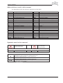
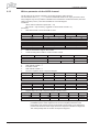
Previous editions
Edition
01 / 2004
10 / 2005
Page 2
Comments
First edition
Appendix added, some changes, Revision
User manual PROFIBUS DP PMCtendo DD4
Contents
Page
Contents
. . . . . . . . . . . . . . . . . . . . . . . . . . . . . . . . . . . . . . . . . . . . . . . . . . . . . . . . . . . 3
Safety instructions
. . . . . . . . . . . . . . . . . . . . . . . . . . . . . . . . . . . . . . . . . . . . . . . . . . 5
Directives and standards
-conformance
. . . . . . . . . . . . . . . . . . . . . . . . . . . . . . . . . . . . . . . . . . . . . 6
. . . . . . . . . . . . . . . . . . . . . . . . . . . . . . . . . . . . . . . . . . . . . . . . . . . . 6
Contents
Contents
1
General
2
Important
2.1
3
About this manual . . . . . . . . . . . . . . . . . . . . . . . . . . . . . . . . . . . . . . . . . . . . . . . . . . . . . . . . . . . . . . . . . . . . . . . . . . . . . . . . . . . 9
Installation / Setup
3.1
Hard- and Software installation. . . . . . . . . . . . . . . . . . . . . . . . . . . . . . . . . . . . . . . . . . . . . . . . . . . . . . . . . . . . . . . . . . . . . . . . 11
3.1.1
Parameterization of the master-interface modules . . . . . . . . . . . . . . . . . . . . . . . . . . . . . . . . . . . . . . . . . . . . . . . . . . . 12
3.1.1.1
Configuration of the control . . . . . . . . . . . . . . . . . . . . . . . . . . . . . . . . . . . . . . . . . . . . . . . . . . . . . . . . . . . . . . . . . 12
3.1.2
Standard functions for data exchange with PMCtendo DD4 . . . . . . . . . . . . . . . . . . . . . . . . . . . . . . . . . . . . . . . . . . . . 13
3.2
Setup . . . . . . . . . . . . . . . . . . . . . . . . . . . . . . . . . . . . . . . . . . . . . . . . . . . . . . . . . . . . . . . . . . . . . . . . . . . . . . . . . . . . . . . . . . . 13
3.2.1
Setup of the basic functions of the servo amplifier . . . . . . . . . . . . . . . . . . . . . . . . . . . . . . . . . . . . . . . . . . . . . . . . . . . 13
4
Profile of PMCtendo DD4
4.1
Parameter channel . . . . . . . . . . . . . . . . . . . . . . . . . . . . . . . . . . . . . . . . . . . . . . . . . . . . . . . . . . . . . . . . . . . . . . . . . . . . . . . . . 16
4.1.1
Parameter ID (PKE) . . . . . . . . . . . . . . . . . . . . . . . . . . . . . . . . . . . . . . . . . . . . . . . . . . . . . . . . . . . . . . . . . . . . . . . . . . 16
4.1.1.1
Interpretation of the response IDs . . . . . . . . . . . . . . . . . . . . . . . . . . . . . . . . . . . . . . . . . . . . . . . . . . . . . . . . . . . . 16
4.1.1.2
Profile-specific error numbers with response ID 7 . . . . . . . . . . . . . . . . . . . . . . . . . . . . . . . . . . . . . . . . . . . . . . . . 17
4.1.2
Subindex IND . . . . . . . . . . . . . . . . . . . . . . . . . . . . . . . . . . . . . . . . . . . . . . . . . . . . . . . . . . . . . . . . . . . . . . . . . . . . . . . 17
4.1.3
Parameter value PWE . . . . . . . . . . . . . . . . . . . . . . . . . . . . . . . . . . . . . . . . . . . . . . . . . . . . . . . . . . . . . . . . . . . . . . . . . 18
4.2
The process data channel . . . . . . . . . . . . . . . . . . . . . . . . . . . . . . . . . . . . . . . . . . . . . . . . . . . . . . . . . . . . . . . . . . . . . . . . . . . 18
5
Using the parameter channel
5.1
5.2
Read/write an amplifier parameter . . . . . . . . . . . . . . . . . . . . . . . . . . . . . . . . . . . . . . . . . . . . . . . . . . . . . . . . . . . . . . . . . . . . . 19
Summary of the parameter numbers . . . . . . . . . . . . . . . . . . . . . . . . . . . . . . . . . . . . . . . . . . . . . . . . . . . . . . . . . . . . . . . . . . . 19
5.2.1
List of the parameter numbers . . . . . . . . . . . . . . . . . . . . . . . . . . . . . . . . . . . . . . . . . . . . . . . . . . . . . . . . . . . . . . . . . . 19
5.2.2
Profile parameters . . . . . . . . . . . . . . . . . . . . . . . . . . . . . . . . . . . . . . . . . . . . . . . . . . . . . . . . . . . . . . . . . . . . . . . . . . . . 22
5.2.2.1
PNU 904/911: PPO-type write/read . . . . . . . . . . . . . . . . . . . . . . . . . . . . . . . . . . . . . . . . . . . . . . . . . . . . . . . . . . . 22
5.2.2.2
PNU 918: PROFIBUS - node addresse . . . . . . . . . . . . . . . . . . . . . . . . . . . . . . . . . . . . . . . . . . . . . . . . . . . . . . . . 22
5.2.2.3
PNU 930: selector for operating modes. . . . . . . . . . . . . . . . . . . . . . . . . . . . . . . . . . . . . . . . . . . . . . . . . . . . . . . . 23
5.2.2.4
PNU 963: baud rate . . . . . . . . . . . . . . . . . . . . . . . . . . . . . . . . . . . . . . . . . . . . . . . . . . . . . . . . . . . . . . . . . . . . . . . 24
5.2.2.5
PNU 965: PROFIDRIVE profile number . . . . . . . . . . . . . . . . . . . . . . . . . . . . . . . . . . . . . . . . . . . . . . . . . . . . . . . 24
5.2.2.6
PNU 970: default parametersr . . . . . . . . . . . . . . . . . . . . . . . . . . . . . . . . . . . . . . . . . . . . . . . . . . . . . . . . . . . . . . . 24
5.2.2.7
PNU 971: non-volatile saving of parameters . . . . . . . . . . . . . . . . . . . . . . . . . . . . . . . . . . . . . . . . . . . . . . . . . . . . 24
5.2.3
General parameters . . . . . . . . . . . . . . . . . . . . . . . . . . . . . . . . . . . . . . . . . . . . . . . . . . . . . . . . . . . . . . . . . . . . . . . . . . 25
5.2.3.1
PNU 1000: instrument ID . . . . . . . . . . . . . . . . . . . . . . . . . . . . . . . . . . . . . . . . . . . . . . . . . . . . . . . . . . . . . . . . . . . 25
5.2.3.2
PNU 1001: manufacturer-specific error register . . . . . . . . . . . . . . . . . . . . . . . . . . . . . . . . . . . . . . . . . . . . . . . . . 25
5.2.3.3
PNU 1002: manufacturer-specific status register . . . . . . . . . . . . . . . . . . . . . . . . . . . . . . . . . . . . . . . . . . . . . . . . 26
5.2.4
Position controller parameters. . . . . . . . . . . . . . . . . . . . . . . . . . . . . . . . . . . . . . . . . . . . . . . . . . . . . . . . . . . . . . . . . . . 27
5.2.4.1
PNU 1250: velocity multiplier . . . . . . . . . . . . . . . . . . . . . . . . . . . . . . . . . . . . . . . . . . . . . . . . . . . . . . . . . . . . . . . . 27
5.2.4.2
PNU 1251: axis type . . . . . . . . . . . . . . . . . . . . . . . . . . . . . . . . . . . . . . . . . . . . . . . . . . . . . . . . . . . . . . . . . . . . . . 27
5.2.5
Position data for the position-control mode . . . . . . . . . . . . . . . . . . . . . . . . . . . . . . . . . . . . . . . . . . . . . . . . . . . . . . . . . 27
5.2.5.1
PNU 1300: position . . . . . . . . . . . . . . . . . . . . . . . . . . . . . . . . . . . . . . . . . . . . . . . . . . . . . . . . . . . . . . . . . . . . . . . 27
5.2.5.2
PNU 1301: velocity . . . . . . . . . . . . . . . . . . . . . . . . . . . . . . . . . . . . . . . . . . . . . . . . . . . . . . . . . . . . . . . . . . . . . . . 27
5.2.5.3
PNU 1302: motion task type . . . . . . . . . . . . . . . . . . . . . . . . . . . . . . . . . . . . . . . . . . . . . . . . . . . . . . . . . . . . . . . . 28
5.2.5.4
PNU 1304: acceleration time . . . . . . . . . . . . . . . . . . . . . . . . . . . . . . . . . . . . . . . . . . . . . . . . . . . . . . . . . . . . . . . . 28
5.2.5.5
PNU 1305: deceleration time . . . . . . . . . . . . . . . . . . . . . . . . . . . . . . . . . . . . . . . . . . . . . . . . . . . . . . . . . . . . . . . . 28
5.2.5.6
PNU 1306: acceleration jolt limiting . . . . . . . . . . . . . . . . . . . . . . . . . . . . . . . . . . . . . . . . . . . . . . . . . . . . . . . . . . . 29
5.2.5.7
PNU 1307: deceleration jolt limiting . . . . . . . . . . . . . . . . . . . . . . . . . . . . . . . . . . . . . . . . . . . . . . . . . . . . . . . . . . . 29
5.2.5.8
PNU 1308: next motion task . . . . . . . . . . . . . . . . . . . . . . . . . . . . . . . . . . . . . . . . . . . . . . . . . . . . . . . . . . . . . . . . 29
5.2.5.9
PNU 1309: start delay . . . . . . . . . . . . . . . . . . . . . . . . . . . . . . . . . . . . . . . . . . . . . . . . . . . . . . . . . . . . . . . . . . . . . 29
5.2.5.10
PNU 1310: copy motion task . . . . . . . . . . . . . . . . . . . . . . . . . . . . . . . . . . . . . . . . . . . . . . . . . . . . . . . . . . . . . . . . 29
5.2.5.11
PNU 1311: Position, 32 Bit floating decimal point format . . . . . . . . . . . . . . . . . . . . . . . . . . . . . . . . . . . . . . . . . . 29
5.2.5.12
PNU 1312: Velocity, 32 Bit floating decimal point format . . . . . . . . . . . . . . . . . . . . . . . . . . . . . . . . . . . . . . . . . . 29
5.2.6
Setup mode: position. . . . . . . . . . . . . . . . . . . . . . . . . . . . . . . . . . . . . . . . . . . . . . . . . . . . . . . . . . . . . . . . . . . . . . . . . . 30
5.2.6.1
PNU 1350: homing . . . . . . . . . . . . . . . . . . . . . . . . . . . . . . . . . . . . . . . . . . . . . . . . . . . . . . . . . . . . . . . . . . . . . . . 30
5.2.6.2
PNU 1351: homing direction . . . . . . . . . . . . . . . . . . . . . . . . . . . . . . . . . . . . . . . . . . . . . . . . . . . . . . . . . . . . . . . . 30
5.2.7
Actual values . . . . . . . . . . . . . . . . . . . . . . . . . . . . . . . . . . . . . . . . . . . . . . . . . . . . . . . . . . . . . . . . . . . . . . . . . . . . . . . . 30
5.2.7.1
PNU 1401: speed . . . . . . . . . . . . . . . . . . . . . . . . . . . . . . . . . . . . . . . . . . . . . . . . . . . . . . . . . . . . . . . . . . . . . . . . 30
User manual PROFIBUS DP PMCtendo DD4
Page 3
Contents
Page
5.2.7.2
PNU 1402: incremental position: actual value . . . . . . . . . . . . . . . . . . . . . . . . . . . . . . . . . . . . . . . . . . . . . . . . . . . 30
5.2.7.3
PNU 1403: SI-position: actual value . . . . . . . . . . . . . . . . . . . . . . . . . . . . . . . . . . . . . . . . . . . . . . . . . . . . . . . . . . 30
5.2.7.4
PNU 1414: Actual position, 32 Bit floating decimal point format . . . . . . . . . . . . . . . . . . . . . . . . . . . . . . . . . . . . . 30
5.2.7.5
PNU 1415: Actual velocity, 32 Bit floating decimal point format . . . . . . . . . . . . . . . . . . . . . . . . . . . . . . . . . . . . . 31
5.2.8
Digital I/O-configuration . . . . . . . . . . . . . . . . . . . . . . . . . . . . . . . . . . . . . . . . . . . . . . . . . . . . . . . . . . . . . . . . . . . . . . . . 31
5.2.8.1
PNU 1450 .. 1453: function of the digital inputs. . . . . . . . . . . . . . . . . . . . . . . . . . . . . . . . . . . . . . . . . . . . . . . . . . 31
5.2.8.2
PNU 1458/1459: function of the digital outputs . . . . . . . . . . . . . . . . . . . . . . . . . . . . . . . . . . . . . . . . . . . . . . . . . . 32
5.2.9
Analog configuration . . . . . . . . . . . . . . . . . . . . . . . . . . . . . . . . . . . . . . . . . . . . . . . . . . . . . . . . . . . . . . . . . . . . . . . . . . 32
5.2.9.1
PNU 1500: configuration of the analog input functions . . . . . . . . . . . . . . . . . . . . . . . . . . . . . . . . . . . . . . . . . . . . 32
5.2.9.2
PNU 1501/1506: configuration of the analog outputs . . . . . . . . . . . . . . . . . . . . . . . . . . . . . . . . . . . . . . . . . . . . . 32
5.2.10
Manufacturer specific object channel (from PNU 1600) . . . . . . . . . . . . . . . . . . . . . . . . . . . . . . . . . . . . . . . . . . . . . . . 33
6
Process data channel
6.1
Instrument control . . . . . . . . . . . . . . . . . . . . . . . . . . . . . . . . . . . . . . . . . . . . . . . . . . . . . . . . . . . . . . . . . . . . . . . . . . . . . . . . . . 35
6.1.1
Control word (STW). . . . . . . . . . . . . . . . . . . . . . . . . . . . . . . . . . . . . . . . . . . . . . . . . . . . . . . . . . . . . . . . . . . . . . . . . . . 38
6.1.2
Status word (ZSW) . . . . . . . . . . . . . . . . . . . . . . . . . . . . . . . . . . . . . . . . . . . . . . . . . . . . . . . . . . . . . . . . . . . . . . . . . . . 39
6.2
Operating modes . . . . . . . . . . . . . . . . . . . . . . . . . . . . . . . . . . . . . . . . . . . . . . . . . . . . . . . . . . . . . . . . . . . . . . . . . . . . . . . . . . 39
6.2.1
Positioning (operating mode 2) . . . . . . . . . . . . . . . . . . . . . . . . . . . . . . . . . . . . . . . . . . . . . . . . . . . . . . . . . . . . . . . . . . 40
6.2.2
Digital speed (operating mode 1) . . . . . . . . . . . . . . . . . . . . . . . . . . . . . . . . . . . . . . . . . . . . . . . . . . . . . . . . . . . . . . . . 41
6.2.3
Analog speed (operating mode -1) [in preparation] . . . . . . . . . . . . . . . . . . . . . . . . . . . . . . . . . . . . . . . . . . . . . . . . . . . 41
6.2.4
Digital torque (operating mode -2). . . . . . . . . . . . . . . . . . . . . . . . . . . . . . . . . . . . . . . . . . . . . . . . . . . . . . . . . . . . . . . . 42
6.2.5
Analog torque (operating mode -3) [in preparation] . . . . . . . . . . . . . . . . . . . . . . . . . . . . . . . . . . . . . . . . . . . . . . . . . . 42
6.2.6
Electronic gearing (operating mode -4) . . . . . . . . . . . . . . . . . . . . . . . . . . . . . . . . . . . . . . . . . . . . . . . . . . . . . . . . . . . . 42
6.2.7
ASCII-channel (operating mode -16). . . . . . . . . . . . . . . . . . . . . . . . . . . . . . . . . . . . . . . . . . . . . . . . . . . . . . . . . . . . . . 43
6.2.8
Initial setting after switch-on (operating mode -126) . . . . . . . . . . . . . . . . . . . . . . . . . . . . . . . . . . . . . . . . . . . . . . . . . . 43
7
Setup softw are
7.1
7.2
8
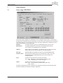
Screen page PROFIBUS . . . . . . . . . . . . . . . . . . . . . . . . . . . . . . . . . . . . . . . . . . . . . . . . . . . . . . . . . . . . . . . . . . . . . . . . . . . . 45
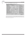
Screen page PROFIBUS instrument control . . . . . . . . . . . . . . . . . . . . . . . . . . . . . . . . . . . . . . . . . . . . . . . . . . . . . . . . . . . . . 46
Sample telegrams
8.1
8.2
8.3
8.4
8.5
8.6
8.7
8.8
8.9
8.10
8.11
8.12
8.13
Important communication parameter . . . . . . . . . . . . . . . . . . . . . . . . . . . . . . . . . . . . . . . . . . . . . . . . . . . . . . . . . . . . . . . . . . .
Zero telegram . . . . . . . . . . . . . . . . . . . . . . . . . . . . . . . . . . . . . . . . . . . . . . . . . . . . . . . . . . . . . . . . . . . . . . . . . . . . . . . . . . . . .
Setting the operating mode. . . . . . . . . . . . . . . . . . . . . . . . . . . . . . . . . . . . . . . . . . . . . . . . . . . . . . . . . . . . . . . . . . . . . . . . . . .
Enable the PMCtendo DD4 . . . . . . . . . . . . . . . . . . . . . . . . . . . . . . . . . . . . . . . . . . . . . . . . . . . . . . . . . . . . . . . . . . . . . . . . . .
Start jog mode . . . . . . . . . . . . . . . . . . . . . . . . . . . . . . . . . . . . . . . . . . . . . . . . . . . . . . . . . . . . . . . . . . . . . . . . . . . . . . . . . . . .
Set reference point . . . . . . . . . . . . . . . . . . . . . . . . . . . . . . . . . . . . . . . . . . . . . . . . . . . . . . . . . . . . . . . . . . . . . . . . . . . . . . . . .
Start homing run . . . . . . . . . . . . . . . . . . . . . . . . . . . . . . . . . . . . . . . . . . . . . . . . . . . . . . . . . . . . . . . . . . . . . . . . . . . . . . . . . . .
Start a motion task . . . . . . . . . . . . . . . . . . . . . . . . . . . . . . . . . . . . . . . . . . . . . . . . . . . . . . . . . . . . . . . . . . . . . . . . . . . . . . . . .
Start a direct motion task . . . . . . . . . . . . . . . . . . . . . . . . . . . . . . . . . . . . . . . . . . . . . . . . . . . . . . . . . . . . . . . . . . . . . . . . . . . .
Polling a warning or error message . . . . . . . . . . . . . . . . . . . . . . . . . . . . . . . . . . . . . . . . . . . . . . . . . . . . . . . . . . . . . . . . . . . .
Writing a parameter . . . . . . . . . . . . . . . . . . . . . . . . . . . . . . . . . . . . . . . . . . . . . . . . . . . . . . . . . . . . . . . . . . . . . . . . . . . . . . . .
Read actual values . . . . . . . . . . . . . . . . . . . . . . . . . . . . . . . . . . . . . . . . . . . . . . . . . . . . . . . . . . . . . . . . . . . . . . . . . . . . . . . . .
Write a parameter via the ASCII channel . . . . . . . . . . . . . . . . . . . . . . . . . . . . . . . . . . . . . . . . . . . . . . . . . . . . . . . . . . . . . . . .
9
Appendix
10
Index
47
48
48
49
49
49
50
52
52
52
53
53
54
Contents
Page 4
User manual PROFIBUS DP PMCtendo DD4
Safety instructions
Safety instructions
l
l
l
l
l
l
l
l
l
Only properly qualified personnel is permitted to carry out activities such as
transport, installation, setup and maintenance. Properly qualified persons
are those who are familiar with transport, installation, assembly, setup and
operation of the products, and who have the appropriate qualifications for
their job. The qualified personnel must know and observe the following
directives and standards:
IEC 364 and CENELEC HD 384 or DIN VDE 0100
IEC-Report 664 or DIN VDE 0110
national accident prevention regulations or BGV A2
Read all the documentation for the servo amplifier before carrying out
installation and setup. Incorrect handling of the servo amplifier can lead to
injury to persons or material damage. It is vital that you keep to the technical
data and information on connection requirements (nameplate and
documentation).
The manufacturer of the machine must generate a hazard analysis for the
machine, and take appropriate measures to ensure that unforeseen
movements cannot cause injury or damage to any person or property.
The servo amplifiers contain electrostatically sensitive components, that
may be damaged by incorrect handling. Discharge your body before
touching the servo amplifier. Avoid contact with highly insulating materials
(artificial fabrics, plastic films etc.). Place the servo amplifier on a
conductive surface.
Do not open the units. Keep all covers and switchgear cabinet doors closed
during operation. Otherwise there are deadly hazards with the possibility of
severe damage to health or property.
Depending on the degree of enclosure protection, servo amplifiers can have
hot surfaces, and bare components that are live. Control and power cables
may carry a high voltage, even when the motor is not rotating.
Servo amplifiers may have hot surfaces during operation. Since the front
panel is used for cooling, it can reach temperatures above 80°C (176°F).
Never undo the electrical connections of the servo amplifier when it is live.
In unfavorable circumstances this can produce electrical arcing that is
damaging both to persons and the equipment.
Wait at least two minutes after disconnecting the servo amplifier from the
supply voltage, before touching any normally live sections of the equipment
(e.g. contacts, screwed connections) or undoing connections. Capacitors
can have dangerous voltages present up to two minutes after switching off
the supply voltages. To be sure, measure the voltage in the intermediate
circuit (DC-link) and wait until it has fallen below 40V.
Safety instructions
User manual PROFIBUS DP PMCtendo DD4
Page 5
Directives and standards
Eurpoean directives and standards
Servo amplifiers are components that are intended to be incorporated into electrical machines and plant.
When the servo amplifiers are incorporated into machines or plant, the intended operation of the servo amplifier is forbidden until it has been established that the machine or plant fulfills the requirements of the
EC Machinery Directive 98/37/EEC and the EC EMC Directive (89/336/EEC). EN 60204 and EN 292 must
also be observed.
The manufacturer of the machine must generate a hazard analysis for the machine, and take appropriate measures to ensure that unforeseen movements cannot cause injury or damage to any person or
property.
In connection with the Low Voltage Directive 73/23/EEC, the harmonized standards of the EN 50178 series
are applied to the servo amplifiers, together with EN 60439-1, EN 60146 and EN 60204.
The manufacturer of the machine or plant is responsible for ensuring that the machine or plant meets the limits that are laid down by the EMC regulations. Advice on the correct installation for EMC – such as shielding,
grounding, arrangement of filters, handling of connectors and laying out the cabling – can be found in the assembly and installation instructions for the servo amplifier.
- conformance
Conformance with the EC Directive on EMC 89/336/EEC and the Low Voltage Directive 73/23/EEC is mandatory for the supply of servo amplifiers within the European Community.
The servo amplifiers of the series have been tested by an authorized testing laboratory in a defined configuration with the system components which are described in this documentation. Any divergence from the
configuration and installation described in this documentation means that you will be responsible for the performance of new measurements to ensure that the regulatory requirements are met.
UL and cUL- Conformance
UL (cUL)-certified servo amplifiers (Underwriters Laboratories Inc.) fulfil the relevant U.S. and Canadian standard (in this case UL 840 and UL 508C).
This standard describes the fulfilment by design of minimum requirements for electrically operated power conversion equipment, such as frequency converters and servo amplifiers, which is intended to eliminate the risk
of fire, electric shock, or injury to persons, being caused by such equipment. The technical conformance with
the U.S. and Canadian standard is determined by an independent UL (cUL) inspector through the type testing
and regular check-ups.
Apart from the notes on installation and safety in the documentation, the customer does not have to observe
any other points in direct connection with the UL (cUL)-certification of the equipment.
UL 508C
UL 508C describes the fulfilment by design of minimum requirements for electrically operated power conversion equipment, such as frequency converters and servo amplifiers, which is intended to eliminate the risk of
fire being caused by such equipment.
UL 840
UL 840 describes the fulfilment by design of air and insulation creepage spacings for electrical equipment and
printed circuit boards.
Directives and standards
Page 6
User manual PROFIBUS DP PMCtendo DD4
Kürzel / Symbole
Abbreviations used in this manual
The abbreviations used in this manual are explained in the table below.
Abbrev.
AGND
AS
BTB/RTO
CAN
CE
CLK
COM
DGND
DIN
Disk
EEPROM
EMC
EMI
EN
ESD
IEC
IGBT
INC
ISO
LED
MB
MS-DOS
Meaning
Analog ground
Restart Lock, option
Ready to operate
Fieldbus (CANopen)
Communité Européenne (EC)
Clock signal
Serial interface for a PC-AT
Digital ground
German Institute for industrial Standards
Magnetic storage (diskette, hard disk)
Electrically erasable programmable memory
Electromagnetic compatibility
Electromagnetic interference
European standard
Electrostatic discharge
International Electrotechnical Commission
Insulated Gate Bipolar Transistor
Incremental Interface
International Standardization Organization
Light-emitting diode
Megabyte
Operating system for PC-AT
Abbrev
NI
NSTOP
PC-AT
PELV
PGND
PSTOP
PWM
RAM
Rregen
RBext
RBint
RES
ROD 426
PLC
SRAM
SSI
SW/SETP.
UL
VAC
VDC
VDE
XGND
Meaning
Zero pulse
Limit-switch input for CCW rotation (left)
Personal computer with 80x86 Processor
Protected low voltage
Ground for the interface
Limit-switch input for CW rotation (right)
Pulse-width modulation
Volatile memory
Regen resistor
External regen resistor
Internal regen resistor
Resolver
A quad B encoder
Programmable logic controller
Static RAM
Synchronous serial interface
setpoint
Underwriters Laboratory
AC voltage
DC voltage
Verein deutscher Elektrotechniker
Ground for the 24V supply
Symbols used in this manual
general warning
general instructions
mechanical hazard
danger to personnel from
electricity and its effects
ð p.
see page (cross-ref.)
l
special emphasis
U
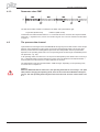
Keys on the servo amplifier panel :
press once : move up one menu item, increase number by one
press twice in rapid succession : increase number by ten
press once : move down one menu item, decrease number by one
press twice in rapid succession : decrease number by ten
hold right key pressed, and then press left key as well :
to enter number, “Return” function
Kürzel / Symbole
U
U
U
User manual PROFIBUS DP PMCtendo DD4
Page 7
This page is deliberately left blank.
Page 8
User manual PROFIBUS DP PMCtendo DD4
1 General
1
General
2
Important
2.1
About this manual
This manual describes the wiring, setup, range of functions and software protocol for the PMCtendo
DD4. It is part of the complete documentation of the PMCtendo DD4 family of digital servo amplifiers.
The installation and setup of the servo amplifier, as well as all the standard functions, are described
in the corresponding manuals.
Further documentation for the PMCtendo DD4 series:
Installation manual PMCtendo DD4
User manual PDrive
This manual is intended for the use of qualified personnel with the following knowledge:
Wiring:
Programming:
trained electro-technical personnel
experienced PLC programmers with PROFIBUS DP expertise
The required files for the drive handling blocks can be found in the folder
"fieldbus\Profibus\Profibus for tendo DD4" of the "Motion Control Tools"-CD ROM.
User manual PROFIBUS DP PMCtendo DD4
Page 9
2 Important
This page is deliberately left blank.
Page 10
User manual PROFIBUS DP PMCtendo DD4
3 Installation / Setup
3
Installation / Setup
3.1
Hard- and Software installation
Install and wire up the equipment only while it is electrically dead. Make sure that the
switchgear cabinet is safely isolated (lock-out, warning signs etc.).
The individual supply voltages will not be switched on until setup is carried out.
Residual charges in the capacitors can still have dangerous levels several minutes after
switching off the supply voltage. Measure the voltage in the intermediate (DC-link) circuit
and wait until it has fallen below 40V.
Power and control connections can still be live, even though the motor is not rotating.
Electronic equipment is basically not failure-proof. The user is responsible for ensuring that,
in the event of a failure of the servo amplifier, the drive is set to a state that is safe for both
machinery and personnel, for instance with the aid of a mechanical brake.
Drives with servo amplifiers and PROFIBUS expansion cards are remote-controlled machines. They can start to move at any time without previous warning. Take appropriate measures to ensure that the operating and service personnel is aware of this danger.
Implement appropriate protective measures to ensure that any unintended start-up of the
machines cannot result in dangerous situations for personnel or machinery. Software
limit-switches are not a substitute for the hardware limit-switches in the machine.
Install the servo amplifier as described in the installation manual. The wiring for the analog
setpoint input and the positioning interface, as shown in the wiring diagram in the installa tion manual, is not required.
Use the valid connection diagram in the amplifier installation manual for the connection to a
PROFIBUS network.
Never break any of the electrical connections to the servo amplifier while it is live. This
could result in destruction of the electronics. Because of the internal representation of the
position-control parameters, the position controller can only be operated if the final limit
speed of the drive at sinusoidal² commutation is not more than 7500 rpm. At trapezoidal
commutation, the permitted maximum speed is 12000 rpm. All the data on resolution, step
size, positioning accuracy etc. refer to calculatory values. Non-linearities in the mechanism
(backlash, flexing, etc.) are not taken into account.
If the final limit speed of the motor has to be altered, then all the parameters that were previously entered for position control and motion blocks must be adapted.
User manual PROFIBUS DP PMCtendo DD4
Page 11
3 Installation / Setup
3.1.1
Parameterization of the master-interface modules
3.1.1.1
Configuration of the control
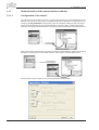
The graphics interface makes it very easy to configure the Siemens S7 for the PROFIBUS network.
After you have set up the control layout, configure the interface module that is used as follows: Use
our library file DD4_045D.GSD for the planning. Open the Hardware catalog and drag the symbol
for the corresponding field unit onto the representation of the bus system. A window opens automatically for the general parameterization of the field unit. Enter the address of the participant here.
Next, use the same method as above to drag the module from the Hardware catalog into the box for
the field unit, whereby the 4-word module must lie in Cell 0 and the 6-word module in Cell 1.
Another window opens, in which you can set the parameters for the module.
Page 12
User manual PROFIBUS DP PMCtendo DD4
3 Installation / Setup
3.1.2
Standard functions for data exchange with PMCtendo DD4
Pilz supplies a function block package (DRIVE_FC). The function block package includes a number
of function blocks that make it possible to handle PMCtendo DD4 control functions very simply.
A description of the individual function blocks can be found as a pdf file on the CD-ROM.
3.2
Setup
3.2.1
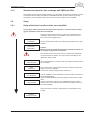
Setup of the basic functions of the servo amplifier
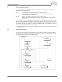
Only properly qualified personnel with professional expertise in control and drive technology are permitted to setup the servo amplifier.
Check that all the safety instructions, which are included in both the
installation manual for the servo amplifier and in this manual, have
been observed and implemented.
Check assembly
+ installation
Connect PC,
start PDrive
Use the setup Software PDrive for setting the parameters for the servo
amplifier.
Caution!
Make sure that any unintended movement of the drive cannot create a danger to personnel or machinery.
Now setup the basic functions of the servo amplifier and optimize the
current and speed controllers. This part of setup is described in the
“Quickstart” setup manual.
Setup the
basic functions
Save
parameters
Test the
bus connection
Test the
communication
When the optimization is finished, save the controller parameters in the
servo amplifier.
Remove the Enable signal (Terminal X3.16) and switch off the power
supply for the servo amplifier.
The 24V DC auxiliary voltage remains switched on.
Test the installation of the PROFIBUS connection and the interface for
the PROFIBUS master.
Check the PROFIBUS-DP parameter settings and the station configuration.
Check the parameter settings for the PROFIBUS interface module.
Check the PLC user program and the parameter settings for the function block packages.
Setup the position controller, as described in the “Quickstart” setup
manual.
Setup the
position controller
User manual PROFIBUS DP PMCtendo DD4
Page 13
3 Installation / Setup
This page is deliberately left blank.
Page 14
User manual PROFIBUS DP PMCtendo DD4
4 Profile of PMCtendo DD4
4
Profile of PMCtendo DD4
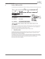
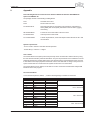
The PROFIBUS-profile PROFIDRIVE includes the following parameter process-data objects (PPO):
PMCtendo DD4 only uses the PPO-type 2 (with 4 words PKW-section and 6 words PZD-section).
The PKW-section is used mainly for the transmission of parameters for the servo amplifier, the
PZD-section is used principally for handling motion functions.
The instrument profile can be divided into two sections or data channels:
1.
PKW-section (4 words)
2.
PZD-section (6 words)
The PKW data channel can also be termed the service channel. The service channel only uses
confirmed communication services, and is used by PMCtendo DD4 as a parameter channel.
This channel has no real-time capability.
The PZD data channel can also be termed the process data channel. The process data channel
uses unconfirmed communication services. The response of the servo amplifier to an unconfirmed
service can only be seen in the reaction of the instrument (status word, actual values).
This channel has real-time capability. - A.4.016.3/1
User manual PROFIBUS DP PMCtendo DD4
Page 15
4 Profile of PMCtendo DD4
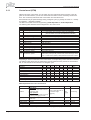
4.1
Parameter channel
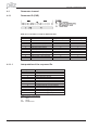
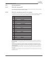
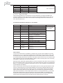
4.1.1
Parameter ID (PKE)
Bold lines in the table are valid for PMCtendo DD4
Task ID
0
1
2
3
4
5
6
7
8
9
10 - 15
4.1.1.1
Master —> Slave
Function
no task
request parameter value
alter parameter value [W]
alter parameter value [DW]
request description element
alter description element
request parameter value [A]
alter parameter value [A/W]
alter parameter value
request number of array elements
reserved
Slave —> Master
Response ID positive
Response ID negative
0
0
1,2
7
1
7/8
2
7/8
3
7
3
7/8
4,5
7
4
7/8
5
7/8
6
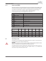
7
Interpretation of the response IDs
Response ID
0
1
2
3
4
5
6
7
8
9
10
11
12
Interpretation
no task
transmit parameter value
transmit parameter value
transmit description element
transmit parameter value
transmit parameter value
transmit number of array elements
task not possible (with error no.)
no operating authority for PKW interface
spontaneous message [W]
spontaneous message [DW]
spontaneous message [A/W]
spontaneous message [A/DW]
Abbreviatoins in the tables:
A:
W:
DW:
Page 16
Array
Word
Double-word - A.4.016.3/3
User manual PROFIBUS DP PMCtendo DD4
4 Profile of PMCtendo DD4
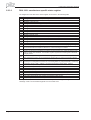
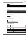
4.1.1.2
Profile-specific error numbers with response ID 7
Error no.
0
1
2
3
4
5
6
7
8
9
10
11
12
13
14
15
16
17
18
19-100
101
102
103
104
105
106
107
108
109
110
111
112
113
114
115
>115
4.1.2
Description
illegal PNU
parameter value cannot be changed
Lower or upper limit violated
Erroneous sub-index
no array
Incorrect data type
setting not allowed (can only be reset)
Descriptive element cannot be changed
PPO-write, requested in IR, not available
descriptive data not available
access group incorrect
No parameter change rights
Password incorrect
Text cannot be read in cyclic data transmission
Name cannot be read in cyclic data transmission
text array not available
PPO-write missing
task cannot be executed due to operating status
other error
reserved
faulty task ID
software error (command table)
only possible in disabled state
only possible in enabled state
BCC-error in the EEPROM data
only possible after task is stopped
wrong value [16,20]
wrong parameter (OCOPY x [- y] z)
wrong motion block no. (0,1..180,192..255)
wrong parameter (PTEACH x [y])
EEPROM write error
wrong value
BCC-error in motion block
Object is read only or write only
Incompatible object (SDO channel only)
reserve
Subindex IND
- A.4.016.3/3
User manual PROFIBUS DP PMCtendo DD4
Page 17
4 Profile of PMCtendo DD4
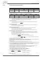
4.1.3
Parameter value PWE
The data for the PNU-variable is contained in the PWE, and is placed flush right:
4-byte data (double-word)
PWE 5-8 (PWE 8 LSB)
Commands are transferred with task ID 3. If a command cannot be executed, the response identification AK = 7 signals the error, and an error number is given out. The error numbers are described
on page 17.
4.2
The process data channel
Cyclical data are exchanged across the PROFIBUS through the process data section of the 20-byte
telegram. Each PROFIBUS cycle triggers an interrupt in the PMCtendo DD4. This has the effect
that new process data are exchanged and processed. The interpretation of these process data
depends on the operating mode that is set. The operating mode is set through a PROFIBUS parameter (PNU 930, ð p. 23).
In all operating modes, the data word 1 of the process data (PZD1) in the direction from control system -> PMCtendo DD4 is used for instrument control, and in the direction from PMCtendo DD4 ->
control system it has the function of a status indicator for the drive.
The interpretation of the process data PZD2 – PZD6 changes, depending on the operating mode,
as can be seen in Chapter 6.2.
Caution:
When the PMCtendo DD4 is switched on, the operating mode that is set is always –126 (safe
state). Before changing the operating mode, bit 10 of the control word STW must always be
set to 0. The new operating mode only becomes active when bit 10 of the control word is set
to 1. - A.4.016.3/3
Page 18
User manual PROFIBUS DP PMCtendo DD4
5 Using the parameter channel
5
Using the parameter channel
The digital servo amplifiers of the PMCtendo DD4 series have to be adapted to the circumstances
of your machine. The parameters for the controllers are set using either the setup Software PDrive
or via the PROFIBUS.
5.1
Read/write an amplifier parameter
Read (AK = 1) or write (AK = 3) amplifier parameters
To read or write an amplifier parameter, which is recognized by the parameter number (PNU), to the
volatile memory of the PMCtendo DD4. The parameters that are stored in the PMCtendo DD4 can
be transferred to the non-volatile memory by using the command “non-volatile parameter save”
(PNU 971).
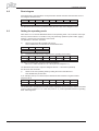
Telegram layout:
PKE/AK
PKE/PNU
PWE
5.2
Request
1 (read) / 3 (write)
see 5.2.1
for AK = 3 see 5.2.1 for data type
for AK = 1 data type irrelevant
Response
2 (OK) / 7 (error)
as transmitted
for AK = 3 returns the PWE of the request
for AK = 1 see 5.2.1 for data type
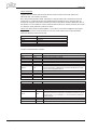
Summary of the parameter numbers
All the parameter numbers for PMCtendo DD4 are listed in numerical order in the table in Chapter
5.2.1, with a short description. The parameter numbers in the range 900 – 999 are profile-specific
for the PROFIBUS drive profile PROFIDRIVE. Parameter numbers > 999 are manufacturer- specific.
For better understanding, you can look up the ASCII commands which are in the column
“PMCtendo DD4 ASCII command” in the user manual for the Setup Software PDrive.
This section deals only with parameters that refer to the PROFIBUS expansion card and have not
already been described in the setup software manual. The attachment runs via the ASCII-commands.
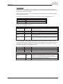
5.2.1
List of the parameter numbers
PNU
Data type
Profile parameter
904 UINT32
911 UINT32
918 UINT32
930 UINT32
963 UINT32
965 Octet-String2
970 UINT32
971 UINT32
1204 UINT32
1205 UINT32
1206 UINT32
1207 UINT32
1208 UINT32
Access Description
ro
ro
ro
r/w
ro
ro
wo
wo
r/w
r/w
r/w
r/w
r/w
User manual PROFIBUS DP PMCtendo DD4
Number of the supported PPO-write, always 2
Number of the supported PPO-read, always 2
Participant address on PROFIBUS
Selector for operating mode
PROFIBUS baud rate
Number of the PROFIDRIVE profile (0302H)
Load default parameter set
non-volatile parameter save
Setpoint ramp-, speed controller
Emergency stop ramp, speed controller
Maximum speed
Overspeed
Count direction
PMCtendo DD4
ASCII command
ADD
RSTVAR
SAVE
DEC
DECSTOP
VLIM
VOSPD
DIR
Page 19
5 Using the parameter channel
PNU
Data type
PMCtendo DD4
ASCII command
Access Description
Manufacturer-specific parameters PMCtendo DD4
General parameters
1000 Visible String4
ro
Instrument ID
1001 UINT32
ro
Manufacturer-specific error register
1002 UINT32
ro
Manufacturer-specific status register
Speed controller parameters
1200 UINT32
r/w
Kp – gain factor for speed controller
1201 UINT32
r/w
Tn – integral-action time for speed controller
1202 UINT32
r/w
PID – T2 – time constant for speed controller
1203 UINT32
r/w
Setpoint ramp+, speed controller
1204 UINT32
r/w
Setpoint ramp-, speed controller
1205 UINT32
r/w
Emergency stop ramp, speed controller
1206 UINT32
r/w
Maximum speed
1207 UINT32
r/w
Overspeed
1208 UINT32
r/w
Count direction
Position controller parameters
1250 UINT32
r/w
Velocity multiplier for jogging/homing
1251 UINT32
r/w
Axis type
1252 INTEGER32
r/w
InPosition window
1253 INTEGER32
r/w
Contouring error window
1254 INTEGER32
r/w
Position register 1
1255 INTEGER32
r/w
Position register 2
1256 INTEGER32
r/w
Position register 3
1257 INTEGER32
r/w
Position register 4
1258 UINT32
r/w
Denominator resolution
1259 UINT32
r/w
Numerator resolution
1260 UINT32
r/w
Minimum acceleration/braking time
1261 UINT32
r/w
Feed-forward factor for position controller
1262 UINT32
r/w
KV - factor for position controller
1263 UINT32
r/w
KP - factor for position controller
1264 UINT32
r/w
Tn - integral-action time for position controller
1265 UINT32
r/w
Maximum velocity for positioning mode
1266 UINT32
r/w
Configuration variable for software switch
1267 UINT32
r/w
Configuration variable 2 for software switch
Position data for the position control mode
1300 INTEGER32
r/w
Position
1301 INTEGER16
r/w
Velocity
1302 UINT32
r/w
Motion task type
1304 UINT32
r/w
Starting time (acceleration)
1305 UINT32
r/w
Braking time (deceleration)
1306 UINT32
r/w
Jolt limiting (acceleration)
1307 UINT32
r/w
Jolt limiting (deceleration)
1308 UINT32
r/w
Number of next motion task
1309 UINT32
r/w
Start delay for next motion task
1310 2 * UINT16
wo
Copy a motion task
Position set-up mode
1350 UINT32
r/w
Homing type
1351 UINT32
r/w
Homing direction
1352 UINT32
r/w
Acceleration ramp (jogging/homing)
1353 UINT32
r/w
Braking ramp
1354 UINT32
r/w
Reference offset
1355 UINT32
ro
Homing run velocity
1356 UINT32
ro
Jogging velocity
Page 20
ERRCODE
GV
GVTN
GVT2
ACC
DEC
DECSTOP
VLIM
VOSPD
DIR
VMUL
POSCNFG
PEINPOS
PEMAX
SWE1
SWE2
SWE3
SWE4
PGEARO
PGEARI
PTMIN
GPFFV
GP
GPV
GPTN
PVMAX
SWCNFG
SWCNFG2
O_P
O_V
O_C
O_ACC1
O_DEC1
O_ACC2
O_DEC2
O_FN
O_FT
OCOPY
NREF
DREF
ACCR
DECR
ROFFS
VREF
VJOG
User manual PROFIBUS DP PMCtendo DD4
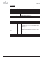
5 Using the parameter channel
PNU
Data type
Actual values
1400 INTEGER32
1401 INTEGER32
1402 INTEGER32
1403 INTEGER32
1404 INTEGER32
1405 INTEGER32
1406 INTEGER32
1407 INTEGER32
1408 INTEGER32
1409 INTEGER32
1410 INTEGER32
1411 INTEGER32
1412 INTEGER32
1413 INTEGER32
Digital I/O configuration
1450 UINT32
1451 UINT32
1452 UINT32
1453 UINT32
1454 INTEGER32
1455 INTEGER32
1456 INTEGER32
1457 INTEGER32
1458 INTEGER32
1459 INTEGER32
1460 UINT32
1461 UINT32
1462
UINT32
Access Description
PMCtendo DD4
ASCII command
ro
ro
ro
ro
ro
ro
ro
ro
ro
ro
ro
ro
ro
ro
Actual position 20 bits/turn
Speed
Incremental position, actual value
SI-position, actual value
SI-velocity, actual value
SI contouring error
RMS current
SI-speed, actual value
Heatsink temperature
Internal temperature
DC-bus (DC-link) voltage
Ballast power
I2t - loading
Running time
PRD
r/w
r/w
r/w
r/w
r/w
r/w
r/w
r/w
r/w
r/w
r/w
r/w
Function of digital input 1
Function of digital input 2
Function of digital input 3
Function of digital input 4
Auxiliary variable for digital input 1
Auxiliary variable for digital input 2
Auxiliary variable for digital input 3
Auxiliary variable for digital input 4
Function of digital input 1
Function of digital input 2
Auxiliary variable for digital output 1
Auxiliary variable for digital output 2
State of four digital inputs, Enable,
2 digital outputs
IN1MODE
IN2MODE
IN3MODE
IN4MODE
IN1TRIG
IN2TRIG
IN3TRIG
IN4TRIG
O1MODE
O2MODE
O1TRIG
O2TRIG
r/w
Analog configuration
1500 UINT32
r/w
Configuration of the analog input functions
1501 UINT32
r/w
Configuration monitor function analog output 1
1502 UINT32
r/w
Offset voltage for analog input 1
1503 UINT32
r/w
Filter time constant for analog input 1
1504 UINT32
r/w
Scaling factor for velocity, analog input 1
1505 UINT32
r/w
Scaling factor for current, analog input 1
1506 UINT32
r/w
Configuration monitor function analog output 2
1507 UINT32
r/w
Offset voltage for analog input 2
1508 UINT32
r/w
Scaling factor for velocity, analog input 2
1509 UINT32
r/w
Scaling factor for current, analog input 2
Motor parameters
1550 UINT32
r/w
Brake configuration
1551 UINT32
r/w
Motor number from motor database
Manufacturer specific object channel
PFB
PV
PE
I
V
TEMPH
TEMPE
VBUS
PBAL
I2T
TRUN
STATIO
ANCNFG
ANOUT1
ANOFF1
AVZ1
VSCALE1
ISCALE1
ANOUT2
ANOFF2
VSCALE2
ISCALE2
MBRAKE
MNUMBER
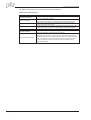
³1600 Þ p. 33 and description of the ASCII-commands on the CD-rom (4th quarter 2002).
Abbreviations in the “Access” column
The “Access” column shows which type of access (e.g read/write) is possible via the bus.
Abbrev.
wo
ro
r/w
Description
“write only” access
“read only” access
read/write access
User manual PROFIBUS DP PMCtendo DD4
Page 21
5 Using the parameter channel
5.2.2
Profile parameters
5.2.2.1
PNU 904/911: PPO-type write/read
These parameters describe the numbers of the supported PPO-types write und read.
Since only PPO-type 2 is supported (see Chapter 4), this parameter is always set to 2.
5.2.2.2
PNU 918: PROFIBUS - node addresse
With this parameter the PROFIBUS - node address of the drive can be read.
You can alter the node address (station addres in a PROFIBUS network) in different ways:
l
With the keys in the front panel (see installation manual)
l
With the setup software PDrive on the screen page "Basic setup"
l
Via the serial interface with the sequence of ASCII-commands:
ADDR nn Þ SAVE Þ COLDSTART (mit nn = Adresse)
The range of addresses can be extended from 1..63 to 1..127 with the ASCII-command MDRV.
Page 22
User manual PROFIBUS DP PMCtendo DD4
5 Using the parameter channel
5.2.2.3
PNU 930: selector for operating modes
The “Selector for operating modes” is defined by the drive profile, and mirrors the operating modes
of the drive profile to the operating modes of the PMCtendo DD4. The following table shows a summary of the operating modes:
Caution!
If process data are exchanged across the PROFIBUS, then the operating modes of the drive
profile must only be selected with PNU 930.
Operating
mode of
drive profile
2
1
0
-1
-2
-3
-4
-5
-6 to -15
-16
-17 to -125
-126
Operating mode PMCtendo DD4
Description
(ASCII command “OPMODE”)
8
0
1
2
3
4
5
-
Positioning mode according to PROFIDRIVE profile
Digital speed control according to PROFIDRIVE profile
reserved
Speed control, analog setpoint provision (in preparation)
Torque control, digital setpoint provision
Torque control, analog setpoint provision (in preparation)
Position control, electronic gearing
Position control, external trajectory (in preparation)
reserved
ASCII channel for expanded parameterization
reserved
Initial settings when instrument is switched on
The individual operating modes are described in Chapter 6.2. A change of operating mode can only
be undertaken in connection with the control word.
The operating mode must be changed according to the following sequence:
1.
Inhibit setpoints and process data
Bit 10 in the control word is set to 0, so that no new setpoints will be accepted by the
servo amplifier and no new control functions can be initiated. A new operating mode
can, however, be selected while a motion function is being performed.
The control word is only inhibited to the extent that the servo amplifier can always be
switched into a safe state.
2.
Select the new operating mode with PNU 930
The new operating mode is selected with parameter 930 through the parameter channel,
but not yet accepted.
3.
Set/receive the setpoints and actual values
Enter the corresponding setpoints in the setpoint area of the process data.
Here you must take note that the normalization and data formats depend on the operating
mode that is selected. The interpretation of the actual values is also altered (see Chapter
5.2.2.3). The user program must respond accordingly.
4.
Enable the setpoints
Bit 10 of STW is set to 1. The setpoints are immediately accepted and processed.
The new actual values are output with the appropriate normalization and data format.
Caution
In the safe operating mode (-126), no motion functions can be initiated via the PROFIBUS.
However, it is possible to perform motion functions with the aid of the setup Software.
If the operating mode is changed, then motion functions can only be operated via the
PROFIBUS. If the operating mode is changed via another communication channel, then the
drive is emergency braked and the error F21 (Handling error, plug-in card) is signaled.
User manual PROFIBUS DP PMCtendo DD4
Page 23
5 Using the parameter channel
5.2.2.4
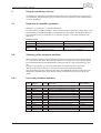
PNU 963: baud rate
This parameter defines the index of the baud rate that is used for PROFIBUS communication, and
can only be read. The baud rate is given out by the PROFIBUS-master.
The table below shows the indices with the according baud rates:
Index
Baud rate
5.2.2.5
0
12000
1
6000
2
3000
3
1500
4
500
5
187.5
6
93.75
7
45.45
8
19.2
9
9.6
PNU 965: PROFIDRIVE profile number
This parameter can be used to read out the number of the PROFIDRIVE profile. Profile Number 3,
Version 2 is used.
5.2.2.6
PNU 970: default parametersr
With this parameter you can reject all the parameters that are set and load the manufacturer’s
default values.
5.2.2.7
PNU 971: non-volatile saving of parameters
With this parameter you can save all the parameter settings to the EEPROM. To do this, the parameter must have the value PWE = 1 when the transfer takes place.
Page 24
User manual PROFIBUS DP PMCtendo DD4
5 Using the parameter channel
5.2.3
General parameters
5.2.3.1
PNU 1000: instrument ID
The instrument ID consists of four ASCII characters, with the contents “S6xx”, whereby xx stands
for the current level of the output stage (e.g. S606).
5.2.3.2
PNU 1001: manufacturer-specific error register
The assignment of the error register can be seen in the following table. The explanation of the individual errors can be found in the assembly & installation instructions for the servo amplifier.
Bit
0
1
2
3
4
5
6
7
8
9
10
11
12
13
14
15
16
17
18
19
20
21
22
23
24
25
26
27-30
31
Description
Error F01:
Error F02:
Error F03:
Error F04*:
Error F05:
Error F06*:
Error F07*:
Error F08:
Error F09*:
Error F10*:
Error F11*:
Error F12*:
Error F13:
Error F14*:
Error F15:
Error F16:
Error F17*:
Error F18*:
Error F19:
Error F20*:
Error F21*:
Error F22:
Error F23:
Error F24:
Error F25:
Error F26:
Error F27:
Error F28 - F31*:
Error F32*:
Heatsink temperature
Overvoltage
Contouring error only with SERCOS
Feedback
Undervoltage
Motor temperature
Auxiliary voltage
Overspeed
EEPROM
Flash-EEPROM
Brake
Motor phase
Internal temperature
Output stage
I²t max.
Mains supply-BTB
A/D-converter
Ballast
Mains supply phase
Slot error
Handling error, plug-in card
Erdschluss
CAN-Bus off
Warning
Commuation error
Limit switch
AS-Option
reserved
System error
When the cause of the error has been cleared, the error state can be canceled by setting Bit 7 in
the control word.
The error response of the PMCtendo DD4 to the reset will differ, depending on the error that has
occurred:
For errors that are marked by an asterisk, setting the reset bit initiates a cold-start of the drive,
whereby the PROFIBUS communication to this instrument will also be interrupted for several seconds. Depending on the circumstances, this break in communication may have to be separately
handled by the PLC.
For the other errors, the reset leads to a warm start, during which the communication will not be
interrupted.
A description of the individual errors and recommendations for removing them can be found in the
installation manual.
User manual PROFIBUS DP PMCtendo DD4
Page 25
5 Using the parameter channel
5.2.3.3
PNU 1002: manufacturer-specific status register
The assignment of the bits for the status register can be seen in the following table:
Bit
0
1
2
3
4
5
6
7
8
9
10
11
12
13
14
15
16
17
18
19
20
21
22
23
24
25
26
27
28
29
30
31
Description
Warning 1: I²t threshold exceeded (set, as long as Irms is above the threshold)
Warning 2: Ballast power exceeded (set, as long as the set ballast power is exceeded)
Warning 3: Contouring error
Warning 4: Threshold monitoring (field bus) active
Warning 5: Mains supply phase missing
Warning 6: Software limit-switch 1 has been activated
Warning 7: Software limit-switch 2 has been activated
Warning 8: Faulty motion task has been started
Warning 9: No reference point was set at the start of the motion task
Warning 10: PSTOP active
Warning 11: NSTOP active
Warning 12: Motor default values were loaded (HIPERFACE® only)
Warning 13: Expansion card is not working properly
Warning 14: SinCos commutation not carried out
Warning 15: Speed - current table error INXMODE 35
Warning 16: Reserve
Motion task active (is set as long as a position control task is active - motion task, jogging, homing).
Reference point set (is set after a homing run, or when an absolute position (multi-turn) encoder is used.
This is canceled when the amplifier is switched on, or when a homing run is started.
Actual position = home position (is set as long as the reference switch is activated).
InPosition (is set as long as the difference between the target position for a motion task and the actual
position is smaller than PEINPOS. The InPosition signal is suppressed if a following task is started at
the target position.
Position latch set (positive edge) – this is set if a rising edge is detected on the INPUT2 (IN2MODE=26)
that is configured as a latch. This is canceled if the latched position is read out (LATCH16/LATCH32)
—
Position 1 reached (is set if the configured condition for this signal (SWCNFG, SWE1, SWE1N) is met.
Depending on the configuration, this bit is set on exceeding SWE1, or going below SWE1, on reaching
the InPosition window SWE1...SWE1N or on leaving the InPosition window SWE1...SWE1N.
Position 2 reached (see above)
Position 3 reached (see above)
Position 4 reached (see above)
Initialization completed (is set if the internal initialization of the amplifier is completed).
—
Speed = 0 (is set as long as the motor speed is below the standstill threshold VEL0).
Safety relay has been triggered (is set as long as the safety relay is open – AS-Option)
Output stage enabled (is set when software and hardware enables are set).
Error present (is canceled when the amplifier is switched on, or if the function “Cancel error” is called.
In the process data, Bits 16 to 31 of the manufacturer-specific status register are given out.
Warnings 3 and 4 can be reset through Bit 13 in the control word.
Page 26
User manual PROFIBUS DP PMCtendo DD4
5 Using the parameter channel
5.2.4
Position controller parameters
5.2.4.1
PNU 1250: velocity multiplier
This parameter is used to enter a multiplier for the jogging/homing velocity. The velocity for jogging/homing is given through PZD2 in the control word when jogging/homing is started.
The actual jog velocity is calculated according to the following formula:
VJog,vel . (32Bit ) = VJog, PZD 2 (16Bit ) ´ multiplier (16Bit )
The defaultvalue is 1.
5.2.4.2
PNU 1251: axis type
This parameter is used to define to which type the axis belongs. If a 0 is given as the parameter
value, it is a linear axis. 1 means a rotary axis.
5.2.5
Position data for the position-control mode
5.2.5.1
PNU 1300: position
Since the PMCtendo DD4 calculates all positioning operations internally only on an incremental
basis, there are limitations on the usable range of values for distances that are
given in SI units.
The range for the incremental position covers the values from -231 to (231-1).
The resolution that is determined by the PGEARO (PNU1258) and PGEARI (PNU1259) parameters
and the variable PRBASE fix the sensibly usable range for positioning operations.
The variable PRBASE determines, through the equation n = 2PRBASE , the number of increments per
motor turn. The value of PRBASE can only be 16 or 20.
PGEARO contains the number of increments that must be traversed when the distance to be
moved is PGEARI. The default values for PGEARO correspond to one turn.
The number of turns that can be covered are given as follows:
-2048..+2047 for PRBASE=16 and -32768..+32767 for PRBASE=20
The sensibly usable position range is derived as follows:
PGEARI
PGEARI
for PGEARI <= PGEARO or
-231 *
...(231 - 1) *
PGEARO
PGEARO
31
31
for PGEARI > PGEARO
-2 ...(2 - 1)
5.2.5.2
PNU 1301: velocity
The usable range for the velocity is not limited by the available data area. It is limited by the maximum applicable speed nmax, which is given by the speed parameter VLIM as the final limit speed
for the motor.
The maximum velocity is thus given by:
PGEARI
n SI, max = n max ´
´2PRBASE
PGEARO
with nmax in turns/second
or, in incremental units, as:
v incr . max. = n max ´ 2PRBASE ´
User manual PROFIBUS DP PMCtendo DD4
250ms n max
=
´ 2PRBASE
1sec
4000
with nmax in turns/second
Page 27
5 Using the parameter channel
5.2.5.3
PNU 1302: motion task type
Bit
0
Value
0
1
0
1
1
2
3
4
5
0
1
0
1
0
1
0
1
0
6
1
0
7
1
0
8
1
9
10
11
12
-
0
1
0
13
1
0
14
15
5.2.5.4
1
-
Meaning
The position value (Subindex 1) that is given is evaluated as an absolute position.
The position value that is given is evaluated as a relative traversing distance.
The two following bits then determine the type of relative motion.
If Bit 1and Bit 2 are set to 0 and Bit 0 set to 1, then the relative motion task is performed
according to the “InPosition” bit.
The new target position is given by the old target position plus the traversing distance.
Bit 1 has priority over Bit 2.
If Bit 1and Bit 2 are set to 0 and Bit 0 set to 1, then the relative motion task is performed
according to the “InPosition” bit.
The new target position is given by the actual position plus the traversing distance.
no following task available
There is a following task, but it must be defined through Subindex 0AH.
Change over to next motion task, with braking to 0 at the target position.
Change over to next motion task, without standstill at the target position.
The type of velocity transition is determined by Bit 8.
Change over to next motion task, without evaluating inputs.
A following motion task is started by a correspondingly configured input.
Start the next motion task by Input State = low or if bit 7 = 1after the delay set in
PNU 1309.
Start the next motion task by Input State = high or if bit 7 = 1after the delay set in
PNU 1309.
The next motion task is started immediately.
The next motion task is started after the delay time set by PNU 1309 or, if Bit 6 = 1, previously by a corresponding input signal.
Only for following motion tasks and Bit 4 = 1: from the target position for the previous motion task onwards, the velocity is altered to the value for the following motion task.
The change of velocity is made so that the velocity at the target position of the previous
motion task matches the value given for the following motion task.
reserved
Accelerations are calculated according to the run-up/acceleration and run-down/braking
times for the motion task.
the deceleration/aceleration ramps are interpreted in mm/s²
The target position and target velocity of a motion task are interpreted as increments.
The target position and target velocity are recalculated as increments before the start of
the motion task. The parameters PGEARI and PGEARO are used for this purpose.
The programmed velocity is used as the velocity for the motion task.
The velocity for the motion task is determined by the voltage present on analog input SW1
at the start of the motion task.
reserved
PNU 1304: acceleration time
This parameter defines the total time to reach the target velocity for the motion task.
5.2.5.5
PNU 1305: deceleration time
This parameter defines the total time to reduce the velocity to 0 at the target position.
Page 28
User manual PROFIBUS DP PMCtendo DD4
5 Using the parameter channel
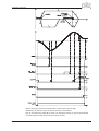
5.2.5.6
PNU 1306: acceleration jolt limiting
This parameter defines the form of the acceleration ramp.
If a value ¹ 0 is entered here, then a sin²-ramp (S-curve) is used to reach the target velocity.
To employ sine²-ramps, the configuration variable SPSET has to be set to 1 (via the ASCII-channel
or the ASCII-terminal in the setup software) and to be saved.
5.2.5.7
PNU 1307: deceleration jolt limiting
This parameter defines the form of the braking/deceleration ramp.
If a value ¹ 0 is entered here, then a sin²-ramp (S-curve) is used for braking/deceleration.
5.2.5.8
PNU 1308: next motion task
The motion task number of the motion task to be started can lie in the range 1 to 180 (motion tasks
in EEPROM) or 192 to 255 (motion tasks in RAM).
5.2.5.9
PNU 1309: start delay
This parameter is used to set a delay time before the start of a motion task.
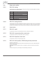
5.2.5.10
PNU 1310: copy motion task
This parameter can be used to copy motion tasks. The source motion task must be entered in the
high-value portion of PWE (PZD 3 & 4) and the target motion task must be entered in the low-value
portion of PWE (PZD 5 & 6).
5.2.5.11
PNU 1311: Position, 32 Bit floating decimal point format
(from SW – Version 0.07)
With this object the target position for motion task 0 (direct motion task, see ASCII – command
O_P) can be set in 32 Bit Floating decimal point format (IEEE).
Right-of-comma positions will be truncated. This objekt is, aside from the data format, identical
PNU 1300. The defaults are indicated in micrometers.
Use:
Controls that support only 16 Bit integer and 32 Bit floating decimal point.
5.2.5.12
PNU 1312: Velocity, 32 Bit floating decimal point format
(from SW – Version 0.07)
With this object the velocity for motion task 0 (direct motion task, see ASCII – command O_V) can
be set in 32 Bit Floating decimal point format (IEEE).
Right-of-comma positions will be truncated. This objekt is, aside from the data format, identical
PNU 1301.
Use:
Controls that support only 16 Bit integer and 32 Bit floating decimal point.
User manual PROFIBUS DP PMCtendo DD4
Page 29
5 Using the parameter channel
5.2.6
Setup mode: position
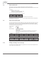
5.2.6.1
PNU 1350: homing
This parameter can be used to determine which type of homing run should be applied. The assignment can be seen in the following table:
PWE
0
1
2
3
4
5
6
7
8
5.2.6.2
Type of homing run
Reference point at the present position
Initiator with resolver zero mark
Hardware limit-switch resolver zero mark
Initiator without resolver zero mark
Hardware limit-switch without resolver zero mark
Zero mark / feedback unit
Reference point at the actual position
Hardware limit-switch with resolver zero mark
Absolute SSI-position
PNU 1351: homing direction
This parameter can be used to determine the direction of motion for homing runs. If a 0 is presented
as the parameter value, then the direction of motion is negative; for a value 1 it is positive, and for a
2 it depends on the distance to the reference point in the direction in which the homing run started.
5.2.7
Actual values
5.2.7.1
PNU 1401: speed
The parameter value is the actual speed of the motor in increments / 250 µsec.
5.2.7.2
PNU 1402: incremental position: actual value
The parameter value is the actual position value in increments.
5.2.7.3
PNU 1403: SI-position: actual value
The parameter value is the actual SI-position value.
5.2.7.4
PNU 1414: Actual position, 32 Bit floating decimal point format
(from SW – Version 0.07)
With this object the actual position (see ASCII-command PFB) can be read in 32 Bit Floating decimal point format (IEEE).
Right-of-comma positions will not be shown. This objekt is, aside from the data format, identical
PNU 1403.
Use:
Controls that support only 16 Bit integer and 32 Bit floating decimal point.
Page 30
User manual PROFIBUS DP PMCtendo DD4
5 Using the parameter channel
5.2.7.5
PNU 1415: Actual velocity, 32 Bit floating decimal point format
(from SW – Version 0.07)
With this object the actual velocity (see ASCII-command PV) can be read in 32 Bit Floating decimal
point format (IEEE).
Right-of-comma positions will not be shown. This objekt is, aside from the data format, identical
PNU 1404.
Use:
Controls that support only 16 Bit integer and 32 Bit floating decimal point.
5.2.8
Digital I/O-configuration
All settings for the digital inputs and outputs only become effective after being saved in the
EEPROM and then switching off and on again, or making a cold start of the PMCtendo DD4. The
significance of the functions can be seen in the user manual for the setup Software.
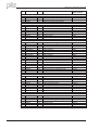
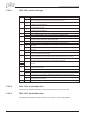
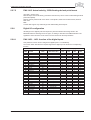
5.2.8.1
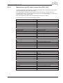
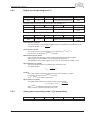
PNU 1450 .. 1453: function of the digital inputs
This parameter can be used to configure the digital inputs 1 to 4 individually.
The column “flank” describes the required signal at the digital input to actuate the corresponding
function.
PWE Function
0
1
2
3
4
5
6
7
8
9
10
11
12
13
14
15
16
17
18
20
21
22
23
24
25
26
27
32
Off
Reset
PSTOP
NSTOP
PSTOP+Intg.Off
NSTOP+Intg.Off
PSTOP+NSTOP
P/Nstop+Intg.Off
SW1/SW2
Fauftr_Bit
Intg.Off
1:1-control
Reference
ROD/SSI
S_fehl_clear
FStart_Folge
FStart_Nr x
FStart_IO
Ipeak2 x
FStart_TIPP x
U_Mon.off
FRestart
FStart2_Nr x
Opmode A/B
Zero_latch
Zero pulse
Emergency stop
Brake
Flank
ì
îLow-active
îLow-active
îLow-active
îLow-active
îLow-active
îLow-active
High/Low
ì
ì
High/Low
ì
High/Low
ì
adjustable
ì
ì
ì
ì
ì
ì
ì
ì
ì
ì
î Low
ì
User manual PROFIBUS DP PMCtendo DD4
Auxiliary variable
(PNU 1454..1457)
Task number
of% Ipeak
v in rpm
Task number
Opmode No.
-
Function n be employed with:
PNU
PNU
PNU
PNU
1450
1451
1452
1453
x
x
x
x
x
x
x
x
x
x
x
x
x
x
x
x
x
x
x
x
x
x
x
x
x
x
x
x
x
x
x
x
x
x
x
x
x
x
x
x
x
x
x
x
x
x
x
x
x
x
x
x
x
x
x
x
x
x
x
x
x
x
x
x
x
x
x
x
x
x
x
x
x
x
x
x
x
x
x
x
x
x
x
x
x
x
Page 31
5 Using the parameter channel
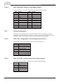
5.2.8.2
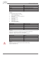
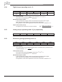
PNU 1458/1459: function of the digital outputs
These parameters can be used to configure the two digital outputs individually.
PWE
0
1
2
3
4
5
6
7
8
9
10
11
12
13
5.2.9
Function
Off
n_act<x
n_act>x
Mains-BTB
Ballast
Sw_end
Pos.>x
InPos
list<x
list>x
S_fault
I²t
PosREG.1
PosREG.2
PWE
14
15
16
17
18
19
20
21
22
23
24
28
29
Function
PosREG.3
PosREG.4
Next-InPos
Error/Warn
Error
DC_Link>x
DC_Link<x
ENABLE
Zero-pulse
Reserve
Ref_OK
PosREG. 0
PosREG. 5
Analog configuration
All settings for the analog inputs and outputs only become effective after being saved in the
EEPROM and then switching off and on again, or making a cold start of the PMCtendo DD4. The
significance of the functions can be seen in the user manual for the setup Software.
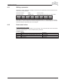
5.2.9.1
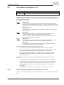
PNU 1500: configuration of the analog input functions
This parameter can be used to configure the two analog inputs together.
PWE
0
1
2
3
4
5
6
7
8
9
5.2.9.2
Function
Xsetp = SW1
N_setp = SW1, Isetp = SW2
unused
Xsetp = SW1, Ipeak = SW2
Xsetp = SW1 + SW2
Xsetp = SW1 * SW2
Electr. gearing
Icmd = SW1, nmax = SW2
Pcmd = SW1
Xcmd = SW1, Ferraris = SW2
PNU 1501/1506: configuration of the analog outputs
This parameter can be used to configure the two analog outputs individually.
PWE
0
1
2
3
4
5
6
Page 32
Function
Off
n act
I act
n setp
I setp
S_fault
Slot
User manual PROFIBUS DP PMCtendo DD4
5 Using the parameter channel
5.2.10
Manufacturer specific object channel (from PNU 1600)
The object catalogue was expanded by all existing parameters and commands from PNU 1600 on
(reserved object range PNU 1600 - PNU 2000).
This object range is called SDO channel (SDO - Service Data Object). The SDO channel is
expansible dynamically, new parameters will be added to the table automatically. The PNU is calculated by 1600 + ASCII object number.
Each of the object in the SDO channel is described by 8 subindexes (octet 3).
In the following, the structure of the subindexes is shown:
Subindex
short description
Unit
Access
Data-type
Value range
EEPROM
0
Number of entries
—
—
UNSIGNED8
0 ... 28-1
—
Subindex
short description
Unit
Access
Data-type
Value range
Defaultvalue
EEPROM
1
read/write a parameter
see corresponding ASCII-command
see corresponding ASCII-command
see corresponding ASCII-command
see corresponding ASCII-command
—
see corresponding ASCII-command
Subindex
short description
Unit
Access
Data-type
Value range
Defaultvalue
EEPROM
2
read lower limit
see corresponding ASCII-command
Read only
see corresponding ASCII-command
see corresponding ASCII-command
—
—
Subindex
short description
Unit
Access
Data-type
Value range
Defaultvalue
EEPROM
3
read upper limit
see corresponding ASCII-command
Read only
see corresponding ASCII-command
see corresponding ASCII-command
—
—
Subindex
short description
Unit
Access
Data-type
Value range
Defaultvalue
EEPROM
4
read defaultvalue
see corresponding ASCII-command
Read only
see corresponding ASCII-command
see corresponding ASCII-command
—
—
User manual PROFIBUS DP PMCtendo DD4
Page 33
5 Using the parameter channel
Subindex
short description
Unit
Access
Data-type
Value range
Defaultvalue
EEPROM
5
read object format
—
Read only
see corresponding ASCII-command
see corresponding ASCII-command
—
—
Desription:
The following object formats are possible:
0
1
2
3
4
5
6
7
8
9
Function (no parameters – write only)
Function (32-Bit parameter)
Function (32-Bit parameter with weighting 3)
8-Bit integer
8-Bit unsigned integer
16-Bit integer
16-Bit unsigned integer
32-Bit integer
32-Bit unsigned integer
32-Bit integer (weighting 3)
Subindex
short description
Unit
Access
Data-type
Value range
Defaultvalue
EEPROM
6
read object control data
—
Read only
UNSIGNED32
0 ... 232 – 1
—
—
Description:
0x00010000 when altered, the variable has to be saved and the amplifier reset
0x00020000 variable will be saved in the serial EEPROM
0x00200000 variable is read-only, must not be written via PROFIBUS
Subindex
short description
Unit
Access
Data-type
Value range
Defaultvalue
EEPROM
7,8
reserved
—
Read only
UNSIGNED32
0 ... 232 - 1
—
—
Caution!
Objects with format 0 (subindex 5) must not be accessed reading
(response identification = 1)
Page 34
User manual PROFIBUS DP PMCtendo DD4
6 Process data channel
6
Process data channel
The process data channel is used for real-time communication. This channel can effectively be
divided into two telegram portions:
PZD1:
Control word (STW) /Status word (ZSW) – instrument control
The control word and the status word are used to control the instrument and
monitor the status of the instrument.
PZD2-6:
Setpoint / actual values depending on the operating mode.
Setpoints and actual values such as position, velocity and current are exchanged
in this section.
The availability of a process data channel is determined in the PROFIDRIVE drive profile. The significance of the process data is defined according to the operating mode. The process data that are
used are determined in such a way that the real-time capability of this channel is optimally used. A
central role is played by the parameter “Selector for operating modes” (see Chapter 5.2.2.3), that is
used to choose between individual operating modes.
In the following, the instrument control is described first, and then the significance and functioning of
the operating modes.
6.1
Instrument control
The control of the instrument is described with the aid of a status machine. The status machine is
defined in the drive profile by a flow diagram for all operating modes. The following diagram shows
the possible instrument states for the PMCtendo DD4.
Output stage not
switched on
Error
Start
Eror response
active
Error
Not ready to
switch-on
Switch-on
inhibited
Ready for
switch-on
Output stage
switched on
Ready for
operation
Operation
enabled
User manual PROFIBUS DP PMCtendo DD4
Fast stop
Page 35
6 Process data channel
The following table describes the instrument states and the transitions.
States of the status machine
State
Not ready for switch-on
Switch-on inhibited
Ready for switch-on
Ready for operation
Operation enabled
Fast stop activated
Error response active/error
Page 36
Description
PMCtendo DD4 is not ready for switch-on. No operation readiness (BTB) is signaled from the amplifier software.
PMCtendo DD4 is ready for switch-on. Parameters can be transferred, DC-link
(DC-bus) can be switched on, motion functions cannot be carried out yet.
DC-link voltage must be applied. Parameters can be transferred, motion
functions cannot be carried out yet.
DC-link voltage must be switched on. Parameters can be transferred, motion
functions cannot be carried out yet. Output stage is switched on (enabled).
No error present. Output stage is switched on, motion functions are enabled.
Drive has been stopped, using the emergency stop ramp. Output stage is
switched on (enabled), motion functions are enabled.
If an instrument error occurs, the PMCtendo DD4 changes to the instrument
state “Error response active”. In this state, the power stage is switched off
immediately. After this error response has taken place, it changes to the state
“Error”. This state can only be terminated by the bit-command “Error-reset”.
To do this, the cause of the error must have been removed (see ASCII
command ERRCODE).
User manual PROFIBUS DP PMCtendo DD4
6 Process data channel
Transitions of the status machine
Transition
Event
0
Action
Event
1
Action
2
3
4
5
6
7
8
9
10
11
12
13
14
15
16
17
Event
Action
Event
Action
Event
Action
Event
Action
Event
Action
Event
Action
Event
Action
Event
Action
Event
Action
Event
Action
Event
Action
Event
Action
Event
Action
Event
Action
Event
Action
Event
Action
Description
Reset / 24V supply is switched on
Initialization started
Initialization successfully completed, PMCtendo DD4 switch-on inhibit
none
Bit 1 (inhibit voltage) and Bit 2 (fast stop) are set in the control word
(command: shutdown). DC-link voltage is present.
none
Bit 0 (switch-on) is also set (command: switch-on)
Output stage is switched on (enabled). Drive has torque.
Bit 3 (operation enabled) is also set (command: operation enable)
Motion functions are enabled, depending on the operating mode that is set.
Bit 3 is canceled (command: inhibit)
Motion functions are disabled.
Drive is braked, using the relevant ramp (depends on operating mode).
Bit 0 is canceled (ready for switch-on).
Output stage is switched off (disabled). Drive has no torque.
Bit 1 or Bit 2 is canceled.
(Command: “Fast stop” or “Inhibit voltage”)
Bit 0 is canceled (operation enabled -> ready for switch-on)
Output stage is switched off (disabled) - motor loses torque.
Bit 1 is canceled (operation enabled -> switch-on inhibited)
Output stage is switched off (disabled) - motor loses torque.
Bit 1 or 2 are canceled (ready for operation -> switch-on inhibited)
Output stage is switched off (disabled) - motor loses torque.
Bit 4 is canceled (operation enabled -> fast stop)
Drive is stopped, using the emergency ramp. The output stage remains enabled. Setpoints are
canceled (e.g motion block number, digital setpoint).
Bit 1 is canceled (fast stop -> switch-on inhibited)
Output stage is switched off (disabled) - motor loses torque.
Error response active
Output stage is switched off (disabled) - motor loses torque.
Error
none
Bit 7 is set (error -> switch-on inhibited)
Acknowledge error (depending on error – with/without reset)
Bit 4 is set (fast stop -> operation enabled)
Motion function is enabled again.
Bit 2 is canceled
Switch-on inhibited, output stage disabled
The state transitions are affected by internal events (e.g. switching off the DC-link voltage) and by
the flags in the control word (Bits 0, 1, 2, 3, 7).
User manual PROFIBUS DP PMCtendo DD4
Page 37
6 Process data channel
6.1.1
Control word (STW)
With the aid of the control word, you can switch from one instrument state to another. In the diagram for the state machine you can see which instrument states can be reached by which transitions. The momentary instrument state can be taken from the status word.
Several states may be passed through during a telegram cycle (e.g. Ready for switch on ® Ready
for operation ® Operation enabled).
The bits in the control word can be (operating-) mode-dependent or mode-independent.
The following table describes the bit assignment in the control word.
Bit
0
1
Name
Switch on
Inhibit voltage
2
Fast stop, switch-on inhibited
3
4
5
6
7
8
9
10
11
12
13
Operation enabled
Fast stop (inhibit rfg)
Pause (stop rfg)
Setpoint enable
Reset Fault
Jogging (on/off)
reserved
PZD (enable/inhibit)
Start homing run (edge)
Manufacturer-specific
Manufacturer-specific
14
Manufacturer-specific
15
Manufacturer-specific
Commentary
—
—
1 -> 0 drive brakes using emergency ramp, axis is disabled
(See also ASCII-commands STOPMODE and DECDIS)
—
1 -> 0 drive brakes using emergency ramp
Mode-dependent, 1 -> 0 stops motion
mode-dependent
only effective with errors
mode-dependent
—
—
mode-dependent
reset the position
acknowledge warnings
only position mode: Bit14 = 1: PZD section is interpreted as direct
motion block (velocity 32-bit, position 32-bit, motion block type 16-bit
Bit14 = 0: PZD section (HSW) is interpreted as motion block number
mode-dependent, digital speed
Depending on the bit combination in the control word, a corresponding control command is defined.
The following table shows the bit combinations and also determines the priorities of the individual
bits, in case several bits are altered in one telegram cycle.
Command
Shutdown
Switch-on
Inhibit voltage
Fast stop (disable)
Fast stop (enable)
Inhibit operation
Enable operation
Reset error
Acknowledge warnings
Bit 13
X
X
X
X
X
X
X
X
1
Bit 7
X
X
X
X
X
X
X
1
X
Bit 4
X
X
X
X
0
X
1
X
X
Bit 3
X
X
X
X
1
0
1
X
X
Bit 2
1
1
X
0
1
1
1
X
X
Bit 1
1
1
0
1
1
1
1
X
X
Bit 0
0
1
X
X
1
1
1
X
X
Transitions
2, 6, 8
3
7, 9, 10, 12
7, 10,11->12
11
5
4, 16
15
-
Bits labeled with X are irrelevant.
Mode-dependent bits in the control word:
Mode
Position
Digital speed
Digital current
Analog speed
Analog current
Trajectory
Bit 5
Motion block:
The parameter that is set in the motion block is used.
Setup operation:
The parameter that is set as a ramp
for homing and jogging is used
Drive brakes, using the preset
speed ramp.
reserved
reserved
reserved
reserved
Bit 6
Bit 8
Bit 11
Start a motion task with evStart
ery transition edge
jogging
(toggle bit).
Start homing
Setpoint enable
reserved
reserved
Setpoint enable
reserved
reserved
reserved
reserved
reserved
reserved
reserved
reserved
reserved
reserved
reserved
Priority of the Bits 6, 8, 11 in position-control mode: 6 (high), 11, 8 (low).
Page 38
User manual PROFIBUS DP PMCtendo DD4
6 Process data channel
6.1.2
Status word (ZSW)
With the aid of the status word, the instrument state can be represented and the transmitted control
word can be verified. If an unexpected condition is reported, as the result of a transmitted control
word, then first of all the boundary conditions for the expected instrument state must be clarified
(e.g. enable of the output stage – hardware + software, application of the DC-link voltage).
The bits in the status word can be mode-dependent or mode-independent.
The following table describes the bit assignment in the status word.
Bit
0
1
2
3
4
5
6
7
8
9
10
11
12
13
14
15
Name
Ready for switch-on
Switched on
Operation enabled
Error
Voltage inhibited
Fast stop
Switch-on inhibit
Warning
Setpoint / actual value monitoring
Remote
Setpoint reached
Limit active
Mode-dependent
Mode-dependent
Manufacturer-specific
Manufacturer-specific
Commentary
------see ASCII command ERRCODE
------see ASCII command STATCODE
only in position-control mode: contouring error indicator
not supported, fixed to 1
only in position mode: In Position
not supported at present
used in ASCII-mode
used in ASCII-mode
used in ASCII-mode
reserved
States of the status machine:
State
Not ready for
switch-on
Switch-on inhibit
Ready for switch-on
Ready for operation
Operation enabled
Error
Error response
Fast stop active
6.2
Bit 6
Bit 5
Bit 4
Bit 3
Bit 2
Bit 1
Bit 0
0
X
X
0
0
0
0
1
0
0
0
0
0
0
X
1
1
1
X
X
0
X
X
X
X
X
X
X
0
0
0
0
1
1
0
0
0
0
1
X
0
1
0
0
1
1
X
0
1
0
1
1
1
X
0
1
Operating modes
The selection of a new operating mode is described in detail in the chapter on the parameter channel. This procedure must be observed and adhered to.
WARNING
Appropriate precautionary measures against damage caused by faulty presentation of data
formats or normalization of the setpoints must be taken by the user.
The possible operating modes are described below. Operating modes with a positive number (1,2)
are defined in the drive profile. Operating modes with a negative number (-1,-2...) are labeled in the
drive profile as being manufacturer-specific modes.
User manual PROFIBUS DP PMCtendo DD4
Page 39
6 Process data channel
6.2.1
Positioning (operating mode 2)
PZD 1
STW
ZSW
PZD 2
motion task no.
or vsetp*
nact (16-bit)
PZD 3
PZD 4
PZD 5
PZD 6
-
-
-
-
manufacturerspecific status
-
actual position (32-bit)
*: for jogging/homing
Deviating assignment of the process-data sections with STW Bit 14=1:
PZD 1
STW
ZSW
PZD 2
PZD 3
direct motion task: Vsetp (32-bit)
nact (16-bit)
PZD 4
PZD 5
position setpoint (32-bit)
manufactureractual position (32-bit)
specific status
PZD 6
motion block type
-
Motion task number
The motion task number of the motion task to be started can lie in the range 1 to 180
(motion tasks in EEPROM) or 192 to 255 (motion tasks in RAM).
Actual speed (16-bit)
The representation of the 16-bit actual speed value is normalized to the parameter for
n act
overspeed VOSPD n act16 =
´ 215
VOSPD
Actual position (32-bit)
The range for the incremental position covers values from -231 to (231-1), whereby one
turn corresponds to 2PRBASE increments.
Manufacturer-specific status
In the process data, the upper 16 bits of the manufacturer-specific status register
(PNU 1002) are made available. The numbering starts again from 0.
The significance of the status register bits can be seen in the table in Chapter 5.2.3.3.
Speed setpoint for a direct motion task
The usable range for the speed is not limited by the available data area. It is limited by
the maximum achievable speed nmax, which is given by the speed parameter VLIM as
the final limit speed for the motor.
The maximum speed is derived from the following formula:
PGEARI
v SI, max = n max ´
´2PRBASE or, as an incremental value, from:
PGEARO
250ms n max
v incr . max. = n max ´ 2PRBASE ´
=
´ 2PRBASE , in each case with nmax in revs/sec
1sec
4000
Position setpoint for a direct motion task
The PMCtendo DD4 calculates all positioning operations internally only on an incremental basis, so
there are limitations on the usable range of values for distances that are
given in SI units.
The range for the incremental position covers the values from -231 to (231-1).
The resolution that is determined by the PGEARO (PNU1258) and PGEARI (PNU1259) parameters
and the variable PRBASE fix the sensibly usable range for positioning operations.
The variable PRBASE determines, through the equation n = 2PRBASE , the number of increments per
motor turn. The value of PRBASE can only be 16 or 20.
PGEARO contains the number of increments that must be traversed when the distance to be
moved is PGEARI. The default values for PGEARO are 1048576 (PRBASE = 20)
or 65536 (PRBASE = 16) and correspond to one turn.
The number of turns that can be covered are given as follows:
-2048..+2047 for PRBASE=16 and -32768..+32767 for PRBASE=20
The sensibly usable position range is derived as follows:
PGEARI
PGEARI
for PGEARI <= PGEARO, or
-231 *
...(231 - 1) *
PGEARO
PGEARO
31
31
for PGEARI > PGEARO
-2 ...(2 - 1)
Motion block type
The various types of motion block are described in Chapter 5.2.5.3.
Page 40
User manual PROFIBUS DP PMCtendo DD4
6 Process data channel
6.2.2
Digital speed (operating mode 1)
PZD 1
STW
PZD 2
NSetp
PZD 3
-
ZSW
nact
-
PZD 4
PZD 5
-
incremental actual position 32-bit
PZD 6
manuf.-specific
status
Deviating assignment of the process data sections with STW Bit 14=1:
PZD 1
STW
PZD 2
PZD 3
nSetp (32-bit)
ZSW
nact (32-bit)
PZD 4
PZD 5
-
incremental actual position 32-bit
PZD 6
manuf.-specific
status
Deviating assignment of the process data sections with STW Bit 15=1:
PZD 1
STW
PZD 2
nSetp
PZD 3
-
ZSW
nact
-
PZD 4
PZD 5
-
position (20 bits/turn and 16 turns)
PZD 6
manuf.-specific
status
Actual speed nact (16-bit)
The representation of the 16-bit actual speed value is normalized to the parameter for the
n act
overspeed VOSPD n act16 =
´ 215
VOSPD
Actual position (32-bit)
The range for the incremental position covers values from -231 to (231-1).
Here one turn corresponds to 2PRBASE increments.
Manufacturer-specific status
In the process data, the upper 16 bits of the manufacturer-specific status register
(PNU 1002) are made available. The numbering starts again from 0.
The significance of the status register bits can be seen in the table in Chapter 5.2.3.3.
Speed setpoint nsetp (16-bit)
The 16-bit speed setpoint is normalized to the parameter for the
overspeed VOSPD.
n setp
n setp16 =
´ 215
VOSPD
Position
The actual position value is an incremental value with a resolution of 24 bits.
Her one turn corresponds to 2PRBASE increments.
So 224 - PRBASE turns can be represented.
Speed values nact (32-bit)
The digital speed values are converted according to the formula.
60 ´ 4000
nsetp/ act (in rpm) = nsetp/ act, dig. ´
32 ´ 2PRBASE
PRBASE
= Increments per Motor turn, 60s/min,
with 2
4000 = Number of position controller cycles / sec.
6.2.3
Analog speed (operating mode -1) [in preparation]
PZD 1
-
PZD 2
-
User manual PROFIBUS DP PMCtendo DD4
PZD 3
-
PZD 4
-
PZD 5
-
PZD 6
-
Page 41
6 Process data channel
6.2.4
Digital torque (operating mode -2)
PZD 1
STW
PZD 2
Isetp
ZSW
Iact
PZD 3
PZD 4
incremental actual position
(32-bit, value range 24-bit)
PZD 5
manuf.-specific
status
PZD 6
-
Actual position (32-bit)
The range for the incremental position covers values from -231 to (231-1).
Here one turn corresponds to 2PRBASE increments.
Manufacturer-specific status
In the process data, the upper 16 bits of the manufacturer-specific status register
(PNU 1002) are made available. The numbering starts again from 0.
The significance of the status register bits can be seen in the table in Chapter 5.2.3.3.
Digital current values (16-bit)
The digital current values are converted as follows:
6.2.5
digital current setpoint
´ I setp
1640
Analog torque (operating mode -3) [in preparation]
PZD 1
-
6.2.6
I [A] =
PZD 2
-
PZD 3
-
PZD 4
-
PZD 5
-
PZD 6
-
PZD 5
manuf. status
PZD 6
-
Electronic gearing (operating mode -4)
PZD 1
STW
ZSW
PZD 2
nact
PZD 3
PZD 4
actual position (32-bit)
Actual speed (16-bit)
The representation of the 16-bit actual speed value is normalized to the parameter for the
n act
overspeed VOSPD n act16 =
´ 215
VOSPD
Actual position (32-bit)
The range for the actual position covers values from -231 to (231-1).
Here one turn corresponds to 2PRBASE increments..
Manufacturer-specific status
In the process data, the upper 16 bits of the manufacturer-specific status register
(PNU 1002) are made available. The numbering starts again from 0.
The significance of the status register bits can be seen in the table in Chapter 5.2.3.3.
Page 42
User manual PROFIBUS DP PMCtendo DD4
6 Process data channel
6.2.7
ASCII-channel (operating mode -16)
PZD 1
STW
ZSW
PZD 2
PZD 3
PZD 4
10 bytes of ASCII-data
10 bytes of ASCII-data
PZD 5
PZD 6
The operating mode “ASCII-channel” is used for parameterizing the PMCtendo DD4.
With this channel, just as with any terminal program, ASCII data can be exchanged with the servo
amplifier via the RS232 interface. The control of the communication is performed by handshake bits
in the control and status words.
The assignment is as follows:
Bit 12:
Control word
Any transition edge on this bit informs the PMCtendo DD4 that valid ASCII data
are available in its process data input section, i.e. that with effect from this moment
valid data must have been entered into the PZD transmission section PZD 2 - PZD 6
by the control system.
Status word
The PMCtendo DD4 confirms that it has accepted the ASCII data, by a transition
edge on this bit.
Bit 13:
Status word
The PMCtendo DD4 uses a “1” in this bit to signal that the ASCII buffer now
contains valid data. A transition edge of Bit 14 in the control word
STW can be used to make the PMCtendo DD4 write the buffer contents to the
PZD reception section of the bus-master.
Bit 14:
Control word
Any transition edge on this bit requests the PMCtendo DD4 to write the contents
of its filled ASCII buffer to the receive process data of the bus master
Status word
The PMCtendo DD4 uses a transition edge on this bit to signal that the ASCII
buffer data have been written to the process data.
When transmitting ASCII data, the following must be observed:
1.
Every ASCII command must be terminated by the “CR LF” character sequence.
2.
If the ASCII command (with CR LF) is shorter than the 10 characters that are available,
then the rest of the telegram must be filled up with bytes with a content 0x00.
3.
ASCII commands that are longer than 10 characters must be divided into more than
one telegram, whereby a maximum of 30 characters can be sent before the buffer
must be read out once.
When evaluating the responses to the transmitted ASCII command, the following must be
observed:
6.2.8
1.
The ASCII response is always terminated by an “End of Text” (EOT = 0x04) character.
2.
Response telegrams can include less than 10 bytes of user data, without the response
being concluded. The telegram must then be filled up with bytes with the value 0x00.
3.
After reading out the buffer, Bit 13 of the status word is reset to “0”, until the buffer
is filled again.
The designation of the end of the ASCII response is in all cases “End of Text”.
Initial setting after switch-on (operating mode -126)
In this state, it is indeed possible to control the state machine, but motion functions cannot be initiated.
User manual PROFIBUS DP PMCtendo DD4
Page 43
6 Process data channel
This page is deliberately left blank.
Page 44
User manual PROFIBUS DP PMCtendo DD4
7 Setup software
7
Setup software
7.1
Screen page PROFIBUS
On the menu page “Amplifier” the “PROFIBUS” screen will appear. Beyond this is a screen page
that displays the PROFIBUS-specific parameters, the bus status, and the data words in the transmit
and receive directions, as seen by the bus-master. This page is helpful when searching for errors
and commissioning the bus communication.
Baudrate:
The baud rate that is given by the PROFIBUS master is shown here.
PNO Identno.:
The PNO identification is the number for PMCtendo DD4 in the list
of ID-numbers of the PROFIBUS user organization.
Address:
Station address of the amplifier. The address is set up on the screen page
“Basic setup” (see function descriptions in the setup Software).
PPO type:
PMCtendo DD4 only supports PPO-type 2 of the PROFIDRIVE profile.
Interface states:
Shows the present status of the bus communication. Data can only be
transferred across the PROFIBUS when the “Communication OK”
message appears.
Input:
The last bus object that was received by the master.
Here PKE: Response to “write parameter operating mode”
PWE: Operating mode = 2 (OK-message)
Output:
The last bus object that was sent by the master.
Here PKE: “write parameter operating mode” (PNU 930)
PWE: Word 2
The data for input/output are only transferred, if the threshold monitoring for the PMCtendo DD4
has been activated in the master’s hardware configuration.
User manual PROFIBUS DP PMCtendo DD4
Page 45
7 Setup software
7.2
Screen page PROFIBUS instrument control
On this screen page the single bits of the control word (SZT) and the status word (ZSW) are shown.
The device status resulting from the status word is visualized in the status machine. The current
status is shown as black, all other are grey. Additionally the previous status is visualized by emphasis of the number of the appropriate arrow.
Page 46
User manual PROFIBUS DP PMCtendo DD4
8 Sample telegrams
8
Sample telegrams
8.1
Important communication parameter
1. EXTWD (PNU 1658): With this parameter, the observation time (watch dog) for the fieldbus-slot
communication can be set. The observation is only active, if a value higher than 0 is assigned to
EXTWD (EXTWD=0, observation switched off) and the output stage is enabled. If the set time ran
off, without the timer being triggered newly, then the warning n04 (response monitoring) is generated and the drive is stopped. The amplifier remains ready for operation and the output stage
enabled. Before a new driving command (setpoint) is accepted, this warning must be deleted (function CLRFAULT or INxMODE=14).
2. ADDR (PNU 918): With this command, the node address of the amplifier is set. When the
address has been changed, all parameters should be saved to the EEPROM and the amplifier
switched off and on again.
Since the modular structure of the PMCtendo DD4 400 as a multi-axis system requires its own
addressing, there is the additional parameter ADDRFB (PNU 2012) for this series, with which a field
bus address deviating from the internal device address can be defined. The setting takes place
exactly as with ADDR.
3. AENA (PNU 1606): With this parameter, the state of the software-enable after switch-on can be
defined. The software-enable allows an external control to enable/disable the output stage. For
amplifiers with analog setpoints (OPMODE=1,3) the software-enable is set automatically after
switch-on and the devices are ready for operation immediately (if hardware-enable is present). For
all others, software-enable will be set to the value of AENA. The variable AENA has also a function
when resetting the amplifier after an error (by digital input 1 or the CLRFAULT command). If an
error can be reset by the software, the software-enable is set to the value of AENA after the error
was cleared. In this way the behavior of the amplifier after a software-reset is similar to the
switch-on reaction.
4. INPT (PNU 1904): With this parameter a delay for the in-position message can be set. With the
start of a motion task the in-position message is deleted and the monitoring of the position is activated after expiration of the adjusted time. This function is particularly important for positioning procedures within the in-position window. In this case it is guaranteed that the in-position message is
suppressed back for a defined time.
User manual PROFIBUS DP PMCtendo DD4
Page 47
8 Sample telegrams
8.2
Zero telegram
At the beginning of communication via the parameter channel and after communication errors a
zero telegram should be sent:
Byte 1
2
3
4
5
6
7
8
0000 0000 0000 0000 0000 0000 0000 0000 0000 0000 0000 0000 0000 0000 0000 0000
PKE
IND
PWE
The PMCtendo DD4 answers, by likewise setting the first 8 byte of the telegram to zero.
8.3
Setting the operating mode
After switch-on or a reset the PMCtendo DD4 is in the operating mode -126, in which it cannot perform any motion functions. To be able to carry out positioning operations (motion tasks, jogging,
homing), it must be set to the position-control mode.
The procedure to do this is as follows:
a)
Set the control word Bit 10 (PZD1, Bit 10) to 0.
This invalidates the process data for the PMCtendo DD4.
Byte 9
10
xxxx x0xx xxxx xxxx
STW
b)
11
12
xxxx xxxx xxxx xxxx
HSW
Transmit a parameterization telegram for the operating mode setting.
Byte 1
2
3
4
5
6
7
8
0011 0011 1010 0010 xxxx xxxx xxxx xxxx 0000 0000 0000 0000 0000 0000 0000 0010
PKE
IND
PWE
The bits in the PKE section have the following significance:
Bit 0 to 10 = PNU 930, Bit 12 to 15 = AK 3 (see also Chapter 4.1.1)
The PMCtendo DD4 sends a response telegram with AK = 2 and mirrors (identical)
the values for PNU and PWE.
c)
Switch on the new operating mode by setting the control word Bit 10 to 1.
This validates the process data.
If, for example, point a) is not observed, the PMCtendo DD4 transmits a negative answer:
(response ID=7)
Byte 1
2
3
4
5
6
7
8
0111 0011 1010 0010 0000 0000 0000 0000 0000 0000 0000 0000 0000 0000 0001 0001
PKE
IND
PWE
The number that is transferred in the PWE section represents the error number, and can be looked
up in the table in Chapter 4.1.1.2. In this case, error no. 17, “Task impossible because of operating
state” will be signaled.
Page 48
User manual PROFIBUS DP PMCtendo DD4
8 Sample telegrams
8.4
Enable the PMCtendo DD4
The hardware enable signal must be applied, as a precondition for enabling the PMCtendo DD4 via
the PROFIBUS.
The enable can be made by setting the bit combination for the “Operation enabled” state in the control word.
Byte 9
10
11
12
xxx0 x1xx 0011 1111 xxxx xxxx xxxx xxxx
STW
HSW
The PMCtendo DD4 then reports back the corresponding state in its status word, or indicates a
warning or error message.
Byte 9
10
11
12
xxxx xx1x 0010 0111 xxxx xxxx xxxx xxxx
ZSW
HSW
8.5
Start jog mode
Jog mode is started in a similar manner to homing. To start, Bit 8 STW must be set. The jog velocity
is given by the product of the 16-bit main setpoint in PZD2 and the multiplier defined by parameter
1250. The sign of the main setpoint determines the direction of movement.
It is not necessary to have a reference point set for jogging.
8.6
Set reference point
Warning:
Take care that the position of the reference point permits the following positioning operations. The parameterized software limit-switches in the PMCtendo DD4 may not be effective.
The axis could then drive up to the hardware limit-switch or the mechanical stop. There is a
danger of damage being caused.
The control word Bit 12 = 1 defines the momentary position as being the reference point. The positioning functions are enabled. The shifting of the zero point (NI-offset) is ineffective.
The replay “Reference point set” is made through Bit 17 in the manufacturer-specific status register
(PNU 1002) or Bit 1 (manufacturer status of the process data).
Conditions:
PNU930 ¹ -16
No motion function active
User manual PROFIBUS DP PMCtendo DD4
manufacturer specific status, process data 5 bit 0
Page 49
8 Sample telegrams
8.7
Start homing run
After switching on the 24V auxiliary voltage the system must first of all carry out a homing
run.
Take care that the position of the machine zero point (reference point) permits the following
positioning operations. The parameterized software limit-switches in the PMCtendo DD4
may not be effective. The axis could then drive up to the hardware limit-switch or the mechanical stop. There is a danger of damage being caused.
If the reference point (machine zero point) is approached too fast, with high moments of inertia in the system, then it might be overrun, and the axis could then drive up to the hardware limit-switch or the mechanical stop. There is a danger of damage being caused.
The homing run is started by STW, Bit 11 = 1. The start of the homing run is detected by a positive
transition edge for Bit 11.
If Bit 11 is set to 0 again, before the reference point has been reached, then the homing run is canceled. Bit 12 ZSW remains at 0 (reference point not set).
A set reference point is a precondition for all the positioning functions of the linear axis.
The reference point switch is wired up to a digital input on the PMCtendo DD4.
Depending on the type of homing run, you can freely shift the zero crossing point of the motor shaft
within one turn, by using the parameter “Zero-point offset” (NI-offset). Furthermore, you can fix the
position value to be the reference point by using the reference offset.
After the homing run, the drive signals “InPosition”, thereby enabling the position controller.
The velocity for the homing run is transmitted with the main setpoint, as a 16-bit value. Multiplying
this by the value of parameter 1250 determines the 32-bit speed. The sign is not evaluated.
Conditions :
State of the state machine = “Operation enabled”
No warning message (ZSW Bit 7 = 0)
The following diagram uses the homing run Type 1 (negative direction of motion, positive rotation,
starting point in negative direction relative to the reference switch) as an example to illustrate the
signal sequence of the relevant bits in the manufacturer-specific state.
Page 50
User manual PROFIBUS DP PMCtendo DD4
8 Sample telegrams
After the homing run has been completed, Bit 11 STW must be set to 0 again.
Alternatively, the reference point can also be set at the actual position.
This can be achieved by setting Bit 12 STW, or by setting the homing run Type 0 with parameter
1350 and subsequent start of the homing run by Bit 11 STW . - A.4.016.3/4
User manual PROFIBUS DP PMCtendo DD4
Page 51
8 Sample telegrams
8.8
Start a motion task
Motion tasks are started by a transition edge (positive or negative) at Bit 6 STW.
Bit 14 STW is used to decide whether a stored motion task or a direct motion task should be carried
out.
Conditions:
Hardware enable is present.
Amplifier is in the “Operation enabled” state.
For linear axis: reference point is set.
Example: start the EEPROM motion task number 10:
Byte 9
10
11
12
0000 0100 0F*11 1111 0000 0000 0000 1010
STW
HSW
* F stands for a transition edge, the state of Bit 6 STW also depends on the previous state.
By setting Bit 5 in the manufacturer-specific status, the amplifier indicates that it has accepted the
motion task and is carrying it out.
8.9
Start a direct motion task
If the motion task data are to be freely defined, then a direct motion task must be used. In this case,
the target position, velocity and type of motion task are transferred to the process data, together
with the call of the motion task. If required, further parameters for this motion task (e.g. ramps) can
be transferred previously by parameter tasks.
Target position
Velocity
Motion task type
Byte 1
0100 0100
135000 mm
mm
20000
s
- relative to actual position
- with following motion task
- without pause
- setpoint velocity for the following task should already be reached at the
target position (only makes sense if there is no change of direction)
- use SI units
2
0F*11 1111
3
0000 0000
PZD1
STW
Byte 7
0000 0000
4
0000 0000
5
0100 1110
PZD2
6
0010 0000
PZD3
vsetp
8
0000 0010
9
0000 1111
10
0101 1000
11
0010 0001
12
0001 1101
PZD4
PZD5
PZD6
motion block type
ssetp
* F stands for a transition edge, the state of Bit 6 STW also depends on the previous state.
8.10
Polling a warning or error message
If a warning or error message is present, then parameter 1001 or 1002 can be interrogated to find
out the number of the warning or error.
Page 52
User manual PROFIBUS DP PMCtendo DD4
8 Sample telegrams
8.11
Writing a parameter
Parameter v_max is used as an example to show how control parameters are transmitted from the
master to the PMCtendo DD4.
Parameter number:
Parameter value:
1265
350000 µm/s
100 1111 0001
0000 0000 0000 0101 0101 0111 0011 0000
Byte 1
2
3
4
5
6
7
8
0011|0100 1111 0001 0000 0000 0000 0000 0000 0000 0000 0101 01010111 0011 0000
AK |
PKE
IND
PWE
Note: after an error has occurred in parameter transmission (AK = 7), a “Zero telegram” should be
transmitted, i.e. the first 8 bytes of the transmit telegram from the PLC should be kept at 0, until the
PMCtendo DD4 has responded with a zero telegram.
8.12
Read actual values
Cyclical actual value request
This PKW task switches on the reading of an actual value. The actual value will now be transmitted
with each cyclical telegram – until a new PKW task is presented.
Telegram layout:
PKE/AK
PKE/PNU
IND
PWE
Request
1
Parameter number of the actual values (1400..1413)
0=
read
no significance
User manual PROFIBUS DP PMCtendo DD4
Response
2
as transmitted
0
actual value
Page 53
8 Sample telegrams
8.13
Write a parameter via the ASCII channel
The KP value for the current controller is to be set through the ASCII channel.
The command is then MLGQ_0.985. Here the understroke stands for an empty character. Since
every telegram only has 10 positions available for the transmission of ASCII characters, the termination of the line (“CR LF”) must be transmitted in a second telegram.
Conditions:
ASCII mode is switched on (PNU 930 = -16)
Bit 13 STW = 0 (if necessary, toggle Bit 14 STW until Bit 13 ZSW = 0)
Procedure:
1.
Write data to PZD 2..6 and invert Bit 12 STW
Byte 1
0001 0000
2
0000 0000
3
0100 1101
4
0100 1100
5
0100 0111
“M”
“L”
“G”
“Q”
8
0011 0000
9
0010 1110
10
0011 1001
11
0011 1000
12
0011 0101
“0”
“.”
“9”
“8”
PZD1
STW
Byte 7
0010 0000
PZD2
PZD4
PZD6
2.
Wait for the transition edge on Bit 12 ZSW
3.
Continue writing data to PZD 2..6 and invert Bit 12 STW
Byte 1
0000 0000
2
0000 0000
3
0000 1101
PZD1
STW
4.
5.
6.
7.
8.
“5”
4
0000 1010
5..12
0000 0000
PZD3..6
PZD2
“CR”
“LF”
Wait for the transition edge on Bit 12 ZSW
Wait until Bit 13 ZSW = 1
Invert Bit 14 STW
Wait until Bit 14 ZSW = 1
The servo amplifier sends a response telegram
Byte 1
0110 0010
2
0000 0000
4
0100 1100
5
0100 0111
“M”
“L”
“G”
“Q”
8
0011 0000
9
0010 1110
10
0011 1001
11
0011 1000
12
0011 0101
“0”
“.”
“9”
“8”
PZD1
ZSW
Byte 7
0010 0000
3
0100 1101
PZD2
PZD4
“_”
9.
6
0101 0001
PZD3
PZD5
PZD6
“5”
Repeat steps 5 to 8 until a response telegram indicates “EOT”.
Byte 1
2
0000 0010
0000 0000
PZD1
ZSW
Note:
Page 54
PZD3
PZD5
“_”
6
0101 0001
3
4
0000 1101
0000 1010
PZD2
“CR”
“LF”
5
6
0000 0100
0000 0000
PZD3
“EOT”
7..12
0000 0000
PZD4..6
The sequence of response telegrams shown above is only one of many
possibilities (for the same response from the servo amplifier). Because of the
transmission rate and the internal synchronization mechanism, it can happen that
process data sections remain empty and so the response is broken into segments.
This could possibly alter the number of response telegrams.
User manual PROFIBUS DP PMCtendo DD4
9 Appendix
9
Appendix
Drive Handling Blocks for Communication between PMCtendo DD4 with PROFIBUS-DP
Option and SIMATIC S7
The package consists of the following handling blocks:
FC21
Send data to the drive
FC22
Receive data from drive
FC100 DRVSTAT
STATUS information of the Profibus communication, transmission of
status (ZSW) and control (STW) information to the servodrive, jogging
and homing
FB102 DRIVEFSS
Function to store motion tasks to the servo drive
FC106 DRIVEFS
Call and process motion tasks
FC110 DRIVEPAR
Transfer of parameters, actual and setpoint values between the PLC and
the servodrive
System requirements
- S7-315-2 DP or other S7-Controller with DP-Operation.
- Simatic Step 7, Version 2.1 or higher
How it works
The function blocks FC21 (Send) and FC22 (Receive) do the communication with the drives by using
the user data block and the parameter data block. They use the parameters of the actual drive from the
parameter data block to transfer data from the user data block to the output peripherie of the CPU and
to read data from the input peripherie and transfer it to the user data block. In doing so they use the S7
system function SFC15 to send and the S7 system function SFC14 to receive data.
The function blocks FC100, FB102, FC106 and FC110 also access the user data block and provide
interfaces for the user program.
The User Data Block
A user data block (DB101, DB102, ...) with the following design is needed for each axis:
Adress
n
...
n + 16
n + 18
n + 20
n + 22
n + 24
n + 26
n + 28
n + 30
n + 32
n + 34
n + 36
n + 38
n + 40
n + 42
n + 44
Name
reserved
...
reserved
PKES
INDS
PWE1S
PWE2S
STW
HSW
PZD3S
PZD4S
PZD5S
PZD6S
PKEE
PKWE
PKE1E
PWE2E
User manual PROFIBUS DP PMCtendo DD4
Comment
Begin of Data Block
Parameter-ID
Parameter-Value 1
Parameter-Value 2
Control Word
Main Setpoint
PKW - Send Panel
PZD - Send Panel
Parameter ID
PKW - Receive Panel
Page 55
9 Appendix
n + 46
n + 48
n + 50
n + 52
n + 54
n + 56
ZSW
HIW
PZD3E
PZD4E
PZD5E
PZD6E
Status Word
Main Actual Value
PZD - Receive Panel
(n = 2, 4, 6, … Begin of user data)
There can be parameters for several drives in one user data block. The number is limited by the
maximum possible block size and by the max. number for the parameter NUDB of FC100. The low
byte of this parameter is the number of the actual drive’s data begin inside the user data block. It’s
max. value therefore is FFh.
The Parameter Data Block (example for 2 axes, DB100)
Adress
0
2
4
6
8
10
12
Name
dbw0
dbw1
dbw2
WDH
ppo_typ
Bus_nr
DB_Nutzdaten
14
Kom_st_wort
16
Peri_PKW
18
Peri_PZD
20
22
24
26
ppo_typ2
Bus_nr2
DB_Nutzdaten2
Kom_st_wort2
28
Peri_PKW2
30
Peri_PZD2
Comment
Reserved
Reserved
Reserved
Reserved
Telegram type PPO2 (fixed)
Slave address of the drive (ADDR)
Number of User Data Block (101)
Begin of user data for slave 1 inside the user
data block ('n', s.a.) (W#16#C)
Startadress of PKW – peripheral range
(W#16#0100)
Startadress PZD - peripheral range
(W#16#0108)
Telegram type PP02
Profibus slave number (ADDR)
Number of User Data Block (102)
Begin of user data (W#16#C)
Start adress PKW - peripheral range
(W#16#0114)
Start adress PZD - peripheral range
(W#16#011C)
System Parameters
(per DP-Master)
How to Handle
To use one of the functions it is mandatory to call the FC100. FC100 must be called first. Out of the
functions FC101 to FC110 only those FCs/FBs must be called that are used. If FB102 is used, make
sure that the call of FC110 that axis is skipped, since FC110 is used by FB102. All calls of FCs/FBs
are made absolutely. Between the call of the FC100 and the calls of FC101 to FC110 no other function
block is allowed to use the scratch flags MW200 – MW254. When processing alarms, the scratch flag
area MW200 – MW254 bust be saved and reloaded.
Seperate function block calls, beginning with the FC100, are required for each drive. Only one task at a
time can be started per drive. The next task can not be started, before the previous one is finished and
BUSY = 0. If data words are declared as parameters to the FCs, they are placed in the parameterized
user data block(FC100 NUDB).
Please notice that due to the change of the data address system of the S7 (byte wise instead of word
wise as for S5) the right byte of the parameter NUDB of FC100 must be interpreted differently. Here
half the value of the start data word is required. However in the parameter data block the start data
word is required. Start data word means that address, where the data for the particular drive starts
inside the user data block. For the example above it means ‘n’ for the parameter Kom_st_wort inside
the parameter data block and ‘n/2’ for the right byte of the paramter NUDB (s.a. description of the
FC100). The FC22 must be called before the FC21! The FC22 and FC21 should be called directly
after the calls oft the handling blocks and within the same function block (FC, FB, OB).
Page 56
User manual PROFIBUS DP PMCtendo DD4
9 Appendix
Description of the Handling Blocks
FC21 (Send)
Inputs:
DBPA
SYPA
SLPA
Integer
Integer
Integer
Number of the parameter data block
reserved
Start adress of the current drive parameters inside the parameter data block.
The FC21 must at least be called once per drive in every PLC cycle.
FC22 (Receive)
Inputs:
DBPA
SYPA
SLPA
Integer
Integer
Integer
Number of the parameter data block
reserved
Start adress of the current drive parameters inside the parameter data block
The FC22 must at least be called once per drive in every PLC cycle.
FC21 and FC22 access the same parameter set and must be parametrized identically for one axis.
FC22 must be called before FC21.
FC100 DRVSTAT
The FC100 establishes the communication beteween the user data block and the other handling
blocks of the package for the parametrized axis. Furthermore it does:
- transmit the control word (except bit 6 and bit 14)
- provide the status word of the drive
- display the Profibus communication status.
Technical Data:
Block Name:
Flags Used:
Access to:
DRVSTAT
MW200-MW254
DB User Data
Function of the parameters of FC100
Inputs:
NUDB
word
STW
word
Outputs:
ZSW
KFEH
BUSY
OFEH
MFEH
word
bool
bool
bool
bool
Static Parameter:
STAT
User manual PROFIBUS DP PMCtendo DD4
left byte: Number of the user data block for the PROFIBUS communication
right byte: Start data word of the user data of the corresponding drive
control word to the drive except Bit6 and Bit14 (which are controlled by
FC106)
Status Word as defined by PROFIDRIVE-Profile
no function
no function
no function
no function
word
internal FC flag word for functions of the package DRIVE FC
Page 57
9 Appendix
FB102 DRIVEFSS
Together with an instance data block the FB102 is used to transfer motion task data for the
PMCtendo DD4. The method is as follows:
Bit 15 of the select parameter WAHL determines if a sample motion task is transferred to the local
motion task no. 0. Inside this motion task individual motion parameters can be changed. After the
changes the complete motion task is transferred to motion task with the number FSNrZ in the drive. If
this transfer is not successful bit 15 of the parameter WAHL will be set. The bits of WAHL not set back
to 0 will show, which parameter could not be written.
Please note: When FB102 is started (SEND = 1) the call of FC110 must be skipped in the program
sequence, since FC110 is used by FB102. FC110 must not be used to read or write parameters,
before the SEND bit of FB102 is set back.
Technical Data:
Name:
Flags used:
Access to:
DRIVEFS
MW200-MW254
DB User Data, Instance Data Block
Function of the Parameters of FB102
Page 58
Inputs:
POSI
VSOL
FART
RACC
RDEC
RACC2
dword
dword
word
word
word
word
RDEC2
word
TDEL
FFOL
FSNrQ
FSNrZ
SEND
word
byte
byte
byte
bool
position for motion task, Bit0 in WAHL
speed for motion task, Bit1 in WAHL
type of motion task, Bit2 in WAHL
acceleration ramp, Bit3 in WAHL
deceleration ramp, Bit4 in WAHL
jerk limitation for acceleration, Bit5 in WAHL
jerk limitation for deceleration, Bit6 in WAHL. Since firmware version 2.00
2
times are discretionary. If different from 0 the drive will follow a sin ramp
(s-curve), if the configuration allows it.
delay time for the next motion task, Bit7 in WAHL
number of the next motion task, Bit8 in WAHL
number of the source motion task; is used, when Bit15 of WAHL = 1
number of target motion task
start transmission
Outputs:
AKTI
bool
FB 102 is running
Static Parameters:
STFB
word
WAHL
word
STAT
REDY
FAUL
word
bool
bool
Statusdisplay for this function block
binary word to select parameters to be written; for interpretation see
above; Bit 15 selects if a motion task is completely overwritten by the direct motion task ( = 0 ) or changed ( = 1); choice is done by setting the
corresponding bit.
Status for all function blocks, same as FC100 STAT
writing motion block finished
error occured, error position -> change of bits in WAHL
User manual PROFIBUS DP PMCtendo DD4
9 Appendix
FC106 DRIVEFS
FC106 selects a motion task and starts its execution. This is done either with data from the drive’s
memory (no.s 1 – 180 EEPROM, 192 – 255 RAM) or as a direct motion task. In the latter case data for
the direct drive parameters is needed.
With linear axes this function will not be executed before a homing sequence is finished successfully,
i.e. the reference point is set.
To be able to run any motion task the drive must be switched to position mode (PNU 930 = 2).
Technical Data:
Name:
Flags used:
DRIVEFS
MW200-MW254
Function of the Parameters of FC106
Inputs:
Fahrsatznummer
word
Direkt_FSart
Direkt_vsoll
Direkt_ssoll
word
dword
dword
Start
bool
VELO
word
number of motion task: 0 – direct motion task, 1..180 EEPROM,
192..255 RAM – motion task
type of direct motion task
32-Bit - Speed setpoint for direct motion task
32-Bit - Position setpoint of direct motion task
start of a motion task with 0->1 edge, 0 - signal before the motion task is
finished will interrupt it(1)
Speed (16 Bit) for jogging and homing, is directly copied to PZD2. The
resulting velocity depends from a multiplication with the value of PNU
1250.
(1)
The source codes of the handling block package include a version of the FC106 (fc106_t), that
starts a motion task with every falling and rising edge of the start signal. When using this version, bit 4
(Fast Stop) or bit 5 (Pause) of the control word must be used to interrupt a motion task. The control
word (except bits 6 and 14) is controlled by FC100.
Outputs:
Istdrehzahl
Istposition
HerstStatus
word
dword
word
actual speed in rpm related to parameter VOSPD
incremental actual position depending on PRBASE
manufacturer specific status word
Static Parameters:
MODUS
word
STAT
word
User manual PROFIBUS DP PMCtendo DD4
Operating mode of servodrive as per PROFIDRIVE profile. This
parameter has to be provided with data by the user. If this value is
unequal to 2, no motion can be started through this function block and no
actual values can be read from this function block.
same flag word as parameterized for FC100 STAT
Page 59
9 Appendix
FC110 DRVPAR
The FC110 is used to read and write the parameters of the servodrive according to the documented
list of parameter numbers (PNUs).
Technical Data:
Name:
Flags used:
DRVPAR
MW200-MW254
Inputs:
PANR
word
PIDX
byte
REWR
STRT
bool
bool
Parameter number according to parameter number table
Subindex to parameter numbers, used only with manufacturer specific
PNUs starting at PNU 1600, otherwise 0
Read/Write - Flag: 0 – read a parameter, 1 – write a parameter
1 - Start a read/ write task, 0 cancels a task
Outputs:
none
Static Parameters:
AKTV
FERT
bool
bool
FEHL
bool
Active display for task, 1 = active
Return message: 1 = parameter could be processed
Fault/error display: 1 = Parameter could not be read or written. In this
case there is an error number in PALO (for evaluation, see the
documentation). When an error occurs, a NULL telegram must be
written (PTYP = 3).
Parametertype: 2 – double word parameter (all parameters in the
servodrive), the parameter number is coming from PANR,
3 = write only, write a NULL telegram, i.e. all data for the PKW
PTYP
byte
channel are set to 0 and transmitted to the SERVOSTAR. A NULL
telegram should be written:
- when starting the communication to drive
- after an error occured (-> FEHL)
- when changing between read and write of one parameter
PAHI
PALO
STAT
Page 60
word
word
word
more significant word of the parameter value
less significant word of the parameter value
same flag word as parameterized for FC100 STAT
User manual PROFIBUS DP PMCtendo DD4
10 Index
10
Index
A
abbreviations . . . . . . . . . . . . . . . . . . 7
acceleration time . . . . . . . . . . . . . . . . 28
actual position value
incremental . . . . . . . . . . . . . . . . 30
SI-units . . . . . . . . . . . . . . . . . . . 30
analog inputs . . . . . . . . . . . . . . . . . . 32
analog outputs . . . . . . . . . . . . . . . . . 32
Antwortkennungen . . . . . . . . . . . . . . . 16
axis type . . . . . . . . . . . . . . . . . . . . 27
B
baud rate . . . . . . . . . . . . . . . . . . . . 24
C
control word . . . . . . . . . . . . . . . . . . 38
Copyright . . . . . . . . . . . . . . . . . . . . 2
D
data format, parameter
deceleration time . . . .
default parameters . . .
digital inputs . . . . . .
digital outputs . . . . .
E
.
.
.
.
.
.
.
.
.
.
.
.
.
.
.
.
.
.
.
.
.
.
.
.
.
.
.
.
.
.
.
.
.
.
.
.
.
.
.
.
.
.
.
.
.
.
.
.
.
.
.
.
.
.
.
.
.
.
.
.
18
28
24
31
32
error numbers . . . . . . . . . . . . . . . . . 17
error register . . . . . . . . . . . . . . . . . . 25
G
Gesamtdokumentation . . . . . . . . . . . . . 9
H
homing . . . . . . . . . . . . . . . . . . . . . 50
homing direction . . . . . . . . . . . . . . . . 30
homing type . . . . . . . . . . . . . . . . . . 30
I
incremental position
installation . . . . .
instrument control .
instrument ID . . . .
instrument profile . .
interface modules .
J
jog mode . . . . . . . . . . . . . . . . . . . . 49
jolt limiting
acceleration . . . . . . . . . . . . . . . . 29
deceleration . . . . . . . . . . . . . . . . 29
M
motion task
copy . . . . . . . . . . . . . . . . . . . . 29
start . . . . . . . . . . . . . . . . . . . . 52
.
.
.
.
.
.
.
.
.
.
.
.
.
.
.
.
.
.
.
.
.
.
.
.
.
.
.
.
.
.
.
.
.
.
.
.
.
.
.
.
.
.
.
.
.
.
.
.
.
.
.
.
.
.
.
.
.
.
.
.
.
.
.
.
.
.
User manual PROFIBUS DP PMCtendo DD4
.
.
.
.
.
.
.
.
.
.
.
.
.
.
.
.
.
.
27
11
35
25
15
12
type . . . . . . . . . . . . . . . . . . . . 28
N
next motion task . . . . . . . . . . . . . . . . 29
O
operating modes . . . . . . . . . . . . . . . . 39
P
parameter channel . . . . . . . .
parameter description . . . . . .
parameter ID . . . . . . . . . . .
parameter numbers . . . . . . .
parameter value . . . . . . . . .
parameterization of the amplifier .
PNU list . . . . . . . . . . . . .
position data . . . . . . . . . . .
process data channel . . . . . .
PROFIDRIVE profile number . .
R
read actual values . . . . . . . . . . . . . . . 53
read/write amplifier parameter . . . . . . . . . 19
response IDs . . . . . . . . . . . . . . . . . . 16
S
safety instructions . . . . . . . . . . . . . . . . 5
sample telegram . . . . . . . . . . . . . . . . 48
saving . . . . . . . . . . . . . . . . . . . . . 24
set reference point . . . . . . . . . . . . . . . 49
Setup . . . . . . . . . . . . . . . . . . . . . . 13
setup software . . . . . . . . . . . . . . . . . 45
speed. . . . . . . . . . . . . . . . . . . . . . 30
standard function blocks . . . . . . . . . . . . 13
start delay . . . . . . . . . . . . . . . . . . . 29
status machine . . . . . . . . . . . . . . . . . 36
status register . . . . . . . . . . . . . . . . . 26
status word . . . . . . . . . . . . . . . . . . . 39
subindex . . . . . . . . . . . . . . . . . . . . 17
V
velocity . . . . . . . . . . . . . . . . . . . . . 27
velocity multiplier . . . . . . . . . . . . . . . . 27
.
.
.
.
.
.
.
.
.
.
.
.
.
.
.
.
.
.
.
.
.
.
.
.
.
.
.
.
.
.
.
.
.
.
.
.
.
.
.
.
.
.
.
.
.
.
.
.
.
.
.
.
.
.
.
.
.
.
.
.
.
.
.
.
.
.
.
.
.
.
16
22
16
19
18
18
19
27
18
24
Page 61
21 522-02, 2005-10 Printed in Germany