1
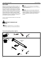
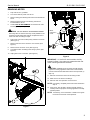
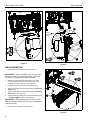
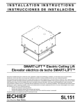
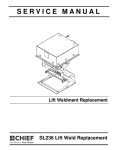
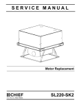
SERVICE MANUAL
Motor Replacement
Spanish Product Description
German Product Description
Portuguese Product Description
Italian Product Description
Dutch Product Description
French Product Description
SL151-SK1 / SL151-SK5
SL151-SK1 / SL151-SK5
Service Manual
DISCLAIMER
CAUTION: A CAUTION alerts you to the possibility of
Milestone AV Technologies and its affiliated corporations and
subsidiaries (collectively "Milestone"), intend to make this
manual accurate and complete. However, Milestone makes no
claim that the information contained herein covers all details,
conditions or variations, nor does it provide for every possible
contingency in connection with the installation or use of this
product. The information contained in this document is subject
to change without notice or obligation of any kind. Milestone
makes no representation of warranty, expressed or implied,
regarding the information contained herein. Milestone assumes
no responsibility for accuracy, completeness or sufficiency of
the information contained in this document.
damage or destruction of equipment if you do not follow the
corresponding instructions.
WARNING: Failure to read, thoroughly understand, and
follow all instructions can result in serious personal injury,
damage to equipment, or voiding of factory warranty! It is the
installer’s responsibility to make sure all components are
properly assembled and installed using the instructions
provided.
Chief® is a registered trademark of Milestone AV Technologies.
All rights reserved.
IMPORTANT WARNINGS AND
CAUTIONS!
WARNING: A WARNING alerts you to the possibility of
serious injury or death if you do not follow the instructions.
TOOLS FOR INSTALLATION / PARTS
5/32"
(included)
A (1)
[Replacement
Motor]
B (1)
[Cable Tie]
C (4)
8-32 x 5/16"
E (1)
10-24 x 7/8"
2
D (1)
5/32"
Service Manual
SL151-SK1 / SL151-SK5
REMOVING MOTOR
1.
Fully lower SL151, if possible.
2.
Turn off and remove power from SL151.
3.
Remove ceiling pan following instructions included with the
SL151.
4.
Remove projector from SL151 following instructions
included with the SL151.
5.
Loosen, BUT DO NOT REMOVE, two screws from chain
tensioning area. (See Figure 1)
CAUTION: DO NOT REMOVE TENSIONING SCREWS!!
Removing either of these screws may cause problems in the
tensioning system which MAY require complete removal of
the SL151 from the ceiling for repair.
6.
Fully loosen one screw to allow plenty of slack in the chain.
(See Figure 1)
7.
Remove and save motor connector cover screws. (See
Figure 2)
8.
Remove motor connector cover. (See Figure 2)
9.
Cut cable tie which is holding motor wiring in place. (See
Figure 2)
9
Motor
Connector
Cover
7
x2
10
10. Unplug motor from control box. (See Figure 2)
Figure 2
IMPORTANT ! : If the SL151 was not able to be fully
lowered (in Step 1) the motor may rotate when the rear
motor mounting screws are removed.
CAUTION: DAMAGE TO SL151 MAY OCCUR! Support
6
projector mounting apparatus while motor is disconnected
until the chain has been removed from the motor sprocket (in
Step 13).
11. Remove and save two rear motor mounting screws.
12. Slide motor to the left out of bushings.
13. Remove chain from sprocket on end of motor.
NOTE: If necessary, completely remove the screw loosened in
Step 6.
14. If the SL151 was not able to be fully lowered (in Step 1),
carefully lower the projector mounting apparatus to the fully
lowered position.
NOTE: If necessary, use a screwdriver or similar tool to guide
the chain around some of the sprockets.
5
x2
Figure 1
3
SL151-SK1 / SL151-SK5
Service Manual
Motor
11
Motor
or
Connector
Cover
11
x2
2
(C) x 2
12
7
(C) x 2
Figure 3
Figure 4
REPLACING MOTOR
1.
Install chain onto sprocket on end of new motor.
6
IMPORTANT ! : When reinstalling chain onto the motor
sprocket, ensure SL151 sides are straight and level or
the lift may not engage limit switches correctly.
2.
Slide motor into bushings and reinstall two rear motor
mounting Phillips screws (removed in Step 11), or two
Phillips 8-32 x 5/16" screws (C). (See Figure 3)
3.
Ensure that chain is routed correctly. (See Figure 5)
4.
Tighten chain using screw loosened in Step 6 of Removing
Motor section.
5.
Tighten one Phillips screw loosened in Step 5 of Removing
Motor section. (See Figure 5)
6.
Tighten remaining socket head cap screw loosened in Step
5 of Removing Motor section. (See Figure 5)
5
4
3
IMPORTANT ! : When tightening chain, ensure SL151
sides are straight and level or the lift may not engage limit
switches correctly.
7.
Plug motor into control box. (See Figure 4)
Figure 5
4
Service Manual
8.
Restore power to SL151.
9.
Verify that SL151 is operating properly when moving up and
down.
SL151-SK1 / SL151-SK5
10. Remove power from SL151.
11. Add cable tie to hold motor wiring in place. (See Figure 4)
12. Replace motor connector cover and reinstall two Phillips
screws (removed in Step 7 of Removing Motor section), or
two Phillips 8-32 x 5/16" screws (C). (See Figure 4)
13. Reinstall the projector into the SL151 following instructions
included with the SL151.
14. Reinstall ceiling pan following instructions included with the
SL151.
15. Restore power to SL151.
5
SL151-SK1 / SL151-SK5
6
Service Manual
Service Manual
SL151-SK1 / SL151-SK5
7
SL151-SK1 / SL151-SK5
Service Manual
USA/International
Europe
Chief Manufacturing, a products division
of Milestone AV Technologies
8820-002007 Rev01
2010 Milestone AV Technologies, a
Duchossois Group Company
www.chiefmfg.com
04/10
Asia Pacific
A
P
F
A
P
F
A
8401 Eagle Creek Parkway, Savage, MN 55378
800.582.6480 / 952.894.6280
877.894.6918 / 952.894.6918
Fellenoord 130 5611 ZB EINDHOVEN, The Netherlands
+31 (0)40 2668620
+31 (0)40 2668615
Office No. 1 on 12/F, Shatin Galleria
18-24 Shan Mei Street
Fotan, Shatin, Hong Kong
P 852 2145 4099
F 852 2145 4477