1
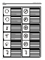
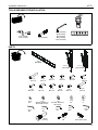
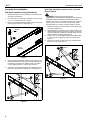
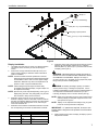
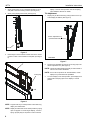
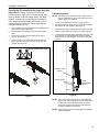
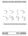
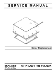
INSTALLATION INSTRUCTIONS
Instrucciones de instalación
Installationsanleitung
Instruções de Instalação
Istruzioni di installazione
Installatie-instructies
Instructions d´installation
Thinstall™ Medium Tilt Universal Mount
Spanish Product Description
German Product Description
Portuguese Product Description
Italian Product Description
Dutch Product Description
French Product Description
MTTU
MTTU
Installation Instructions
DISCLAIMER
Milestone AV Technologies and its affiliated corporations and
subsidiaries (collectively "Milestone"), intend to make this
manual accurate and complete. However, Milestone makes no
claim that the information contained herein covers all details,
conditions or variations, nor does it provide for every possible
contingency in connection with the installation or use of this
product. The information contained in this document is subject
to change without notice or obligation of any kind. Milestone
makes no representation of warranty, expressed or implied,
regarding the information contained herein. Milestone assumes
no responsibility for accuracy, completeness or sufficiency of
the information contained in this document.
Chief® and Thinstall™ are registered trademarks of Milestone
AV Technologies. All rights reserved.
IMPORTANT SAFETY INSTRUCTIONS!
WARNING: A WARNING alerts you to the possibility of
serious injury or death if you do not follow the instructions.
CAUTION: A CAUTION alerts you to the possibility of
damage or destruction of equipment if you do not follow the
corresponding instructions.
WARNING: Failure to read, thoroughly understand, and
follow all instructions can result in serious personal injury,
damage to equipment, or voiding of factory warranty! It is the
installer’s responsibility to make sure all components are
properly assembled and installed using the instructions
provided.
WARNING: Failure to provide adequate structural strength
for this component can result in serious personal injury or
damage to equipment! It is the installer’s responsibility to
make sure the structure to which this component is attached
can support five times the combined weight of all equipment.
Reinforce the structure as required before installing the
component.
WARNING: Exceeding the weight capacity can result in
serious personal injury or damage to equipment! It is the
installer’s responsibility to make sure the combined weight of
all components located between the MTTU up to (and
including) the display does not exceed 100 lbs (45.4 kg). The
wall to which the mount is being attached may have a
maximum drywall thickness of 5/8" (1.6cm).
WARNING: The depth of the display cannot exceed
2 inches (50.8 mm).
WARNING: The MTTU fits all hole patterns between 100 x
100 mm and 600 x 400 mm
2
WARNING: Use this mounting system only for its intended
use as described in these instructions. Do not use
attachments not recommended by the manufacturer.
WARNING: Never operate this mounting system if it is
damaged. Return the mounting system to a service center for
examination and repair.
WARNING: Do not use this product outdoors.
--SAVE THESE INSTRUCTIONS!--
Installation Instructions
MTTU
DIMENSIONS
706
27.81
MAX 23.62 [600]
MIN 3.93 [100]
19
.75
MAX 12°
FLAG
CABLE STAND
RELEASE STRAP
CABLE
ACCESS
ANGLE
MEASUREMENTS: [MILLIMETERS]
INCHES
3
MTTU
Installation Instructions
LEGEND
4
Tighten Fastener
Pencil Mark
Apretar elemento de fijación
Marcar con lápiz
Befestigungsteil festziehen
Stiftmarkierung
Apertar fixador
Marcar com lápis
Serrare il fissaggio
Segno a matita
Bevestiging vastdraaien
Potloodmerkteken
Serrez les fixations
Marquage au crayon
Loosen Fastener
Drill Hole
Aflojar elemento de fijación
Perforar
Befestigungsteil lösen
Bohrloch
Desapertar fixador
Fazer furo
Allentare il fissaggio
Praticare un foro
Bevestiging losdraaien
Gat boren
Desserrez les fixations
Percez un trou
Phillips Screwdriver
Adjust
Destornillador Phillips
Ajustar
Kreuzschlitzschraubendreher
Einstellen
Chave de fendas Phillips
Ajustar
Cacciavite a stella
Regolare
Kruiskopschroevendraaier
Afstellen
Tournevis à pointe cruciforme
Ajuster
Open-Ended Wrench
Remove
Llave de boca
Quitar
Gabelschlüssel
Entfernen
Chave de bocas
Remover
Chiave a punte aperte
Rimuovere
Steeksleutel
Verwijderen
Clé à fourche
Retirez
By Hand
Optional
A mano
Opcional
Von Hand
Optional
Com a mão
Opcional
A mano
Opzionale
Met de hand
Optie
À la main
En option
Hex-Head Wrench
Security Wrench
Llave de cabeza hexagonal
Llave de seguridad
Sechskantschlüssel
Sicherheitsschlüssel
Chave de cabeça sextavada
Chave de segurança
Chiave esagonale
Chiave di sicurezza
Zeskantsleutel
Veiligheidssleutel
Clé à tête hexagonale
Clé de sécurité
Installation Instructions
MTTU
TOOLS REQUIRED FOR INSTALLATION
3/16" (4.8mm)
5/16" (7.9mm)
M2.5 (included)
M3 (included)
M4 (included)
M5 (included)
3/16" (included)
M4 (included)
PARTS
A (1)
[wall plate]
B (1)
[left upright]
D (4)
M7 x 70
K (4)
M6 x 25
R (4)
#10
W (1)
M5
E (4)
M4 x 12
L (4)
M8 x 25
S (4)
shoulder washer for
M4 and M5 screws
X (1)
M4
BB (4)
[anchor]
F (4)
M5 x 12
M (4)
M8 x 20
G (4)
M6 x 12
N (4)
M8 x 16
T (4)
shoulder washer for
M6 screws
H (4)
M4 x 25
P (4)
M8 x 10
U (4)
.25"
Z (1)
M2.5
Y (1)
M3
CC (1)
M4
C (1)
[right upright]
J (4)
M5 x 25
Q (4)
M8 x 40
V (4)
. 5"
AA (1)
3/16"
DD (2)
[extra spring clip]
5
MTTU
Installation Instructions
Assembly And Installation
Wall Plate Installation into Concrete, Concrete
Block or Brick
Wall Plate Installation Using Wood Studs
1.
Determine location for mount keeping in mind display size
and safety requirements.
2.
Use stud finder to locate studs. Wall plate can be mounted
on 2" x 4" wood studs that are 16" apart.
3.
Remove and discard two plastic shipping parts from the wall
plate (one from each end). (See Figure 1)
WARNING: INSTALLING THE MTTU INTO
UNDERRATED OR DAMAGED CONCRETE CAN LEAD TO
SERIOUS INJURY OR DAMAGE TO PRODUCT! When
installing into concrete, only install the MTTU into concrete at
least 8" in depth or into 8"x8"x16" concrete blocks! Never
install the MTTU into cracked, chipped or flaking concrete.
1.
shipping
part
Determine location for mount keeping in mind display size
and safety requirements.
Using wall plate as a template, mark and then drill four 5/16"
diameter pilot holes through mounting surface. Use level to
make sure wall plate is perfectly horizontal. Holes must be
drilled at least 2-1/4" deep. (See Figure 3)
Install four 5/16" anchors (BB) into pilot holes drilled in Step
2. Use a hammer to lightly tap anchors into holes. (See
Figure 3)
Install four connector screws (D) through wall plate holes
and into anchors. (See Figure 3)
2.
3.
3
4.
Front of
wall plate
3
(BB) x 4
x4
2
x4
Figure 1
4.
Using wall plate as template, mark and then drill four 3/16"
diameter pilot holes through mounting surface making sure
the holes are centered in the middle of each stud. Holes
must be drilled at least 2-1/4" deep. (See Figure 2)
5.
Install four connector screws (D) through wall plate and into
pilot holes using M4 Allen Head bit (CC). (See Figure 2)
X4
4
(D) x 4
4
X4
5
(D) x 4
Figure 2
6
Figure 3
Installation Instructions
MTTU
5
(E-Q) x 4
(R) x 4 (if necessary)
(C)
(S or T) x 4 (if necessary)
locking flag in open position
(B)
(U or V) x 4 (if necessary)
Figure 4
Display Installation
5.
1.
Lay display face side down on a level, non-abrasive surface.
Lay down a cloth if necessary to avoid scratching the
screen.
2. Position left and right interface brackets (B and C) over
holes in back of display to determine which holes will be
used for installation.
NOTE: Interface brackets should be positioned so that the
diamond hole in the bracket is located halfway between
the installation holes in order to ensure proper weight
distribution. Brackets may need to be expanded to tilt
position in order to expose installation holes.
WARNING: IMPROPER INSTALLATION CAN LEAD TO
MOUNT FALLING CAUSING SEVERE PERSONAL INJURY
OR DAMAGE TO EQUIPMENT. Displays can weigh in
excess of 40 lbs (18.1). ALWAYS use two people and proper
lifting techniques when installing display.
NOTE: Cable management pull straps should be easily
WARNING: Exceeding the weight capacity can result in
accessible underneath the display. Length of straps can
be adjusted if necessary.
serious personal injury or damage to equipment! It is the
installer’s responsibility to make sure the combined weight of
all components located between the MTTU up to (and
including) the display does not exceed 100 lbs (45.4 kg).
NOTE: Spacers may not be required depending on the type of
display being mounted. They will typically only be used
with recessed or bump-out back screens.
3.
4.
Determine which screws to use to connect interface
brackets to display. Use the screws that fit into the holes on
the back of the display. Make sure screws can make at least
three full turns into mounting holes. If not, select longer
screw from hardware kit.
Determine which washers and shoulder washers to use with
the corresponding screw. Refer to table below for details.
Screw Size
Washers
M4
use R
use S
Shoulder Washers
M5
use R
use S
M6
none
use T
M8
none
none
Install four button head cap screws (E-Q) through required
washers (R) and shoulder washers (S or T), interface
brackets (B and C), spacers (U or V) and into holes on back
of display. (See Figure 4)
NOTE: Make sure locking flags are in the open position before
attaching display to wall plate. Flags are shown in the
open position in Figure 4.
NOTE: Display can be adjusted horizontally as long as guide
hooks are securely attached to wall plate.
IMPORTANT ! : If spacers are required, be sure to use
screws that are longer than the spacers but of the same
diameter!
6.
While supporting both sides of display, lift display up to the
wall plate on the wall.
7
MTTU
Installation Instructions
7.
Slowly guide hooks on top of interface brackets on top of
wall plate in desired mounting location. (See Figure 5)
8.
Slowly swing display toward wall. (See Figure 5)
display in the full vertical position. See "Extra Spring
Clip Installation" Section for details.
Tilt Adjustment
1.
7
Display may be tilted forward by pulling forward on the top
of the display as desired. (See Figure 7)
1
tension adjustment nut
(located inside hole)
8
WALL
Figure 5
9.
Rotate flags on each interface bracket down to the closed
position in order to lock brackets to wall plate. (See Figure
6)
Side View
Figure 7
(A)
2.
Tilt tension is adjustable by using 3/16" hex key (AA) in the
tension adjustment nut. (See Figure 7)
NOTE: Tension should be adjusted equally on each bracket to
ensure even tension distribution.
NOTE: Due to the low profile of the Thinstall Series, certain
displays may have limited tilt capabilities.
locking flag
3.
9
x2
Figure 6
NOTE: Flags should stay in locked position unless removing
display from wall bracket.
NOTE: Display should be held in full vertical position by spring
clips on uprights. For some larger displays, a second
spring clip (DD) may be required in order to hold the
8
To return display to full vertical position, push display back
against wall until spring clips secure display in vertical
position.
Installation Instructions
MTTU
Extra Spring Clip Installation (for larger displays)
IMPORTANT ! : Display should be held in vertical
position by spring clips. Listen for clicking sound when
returning display to the full vertical position. For larger
displays, a second spring clip (DD) may be added to
each upright so that the display can be held in the full
vertical position by these clips. Follow steps below to
install the extra spring clip.
1.
Remove display and attached uprights from wall plate (A) to
gain access to spring clip screws.
2.
Pull out display from uprights to expose existing spring
clips.
3.
Remove hex nuts and screws holding spring clips to
uprights. (See Figure 8)
4.
Use removed hex nuts and screws to install additional
spring clips (DD) along with removed spring clips onto
uprights. (See Figure 8)
3
4
Cable Management
NOTE: For attaching and adjusting cables, the MTTU mount
features a kickstand to allow access without having to
remove display from the wall.
1.
Ensure mount and display are in the upright position.
2.
Slowly pull bottom of display away from wall until kickstand
fully reaches its down position. (See Figure 9)
3.
Slowly release display until kickstand locks against the wall.
4.
Attach or adjust cables as necessary on back of display.
5.
To disengage kickstand, slightly pull display away from wall
and pull down on cable management straps to release
kickstand. Slowly allow display to return to the wall. (See
Figure 9)
display not shown for clarity
(DD) x 2
kickstand in down
position
cables (typical)
cable
management
straps
WALL
Figure 8
2
Figure 9
NOTE: Due to the low-profile design of the Thinstall Series,
displays with cable connections coming straight out of
the back may require 90-degree cable connectors.
Chief offers in-wall accessories that can assist with
recessing cables and connections.
NOTE: Certain displays may have limited space available for
cable management.
9
MTTU
10
Installation Instructions
Installation Instructions
MTTU
11
MTTU
Installation Instructions
USA/International
Europe
Chief Manufacturing, a products
division of Milestone AV Technologies
8800-002092 Rev01
2011 Milestone AV Technologies, a
Duchossois Group Company
www.chiefmfg.com
11/11
Asia Pacific
A
P
F
A
P
F
A
8401 Eagle Creek Parkway, Savage, MN 55378
800.582.6480 / 952.894.6280
877.894.6918 / 952.894.6918
Fellenoord 130 5611 ZB EINDHOVEN, The Netherlands
+31 (0)40 2668620
+31 (0)40 2668615
Office No. 1 on 12/F, Shatin Galleria
18-24 Shan Mei Street
Fotan, Shatin, Hong Kong
P 852 2145 4099
F 852 2145 4477