1
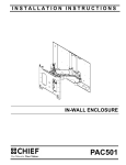
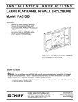
INSTALLATION INSTRUCTIONS
IN-WALL ENCLOSURE
Spanish Product Description
German Product Description
Portuguese Product Description
Italian Product Description
Dutch Product Description
French Product Description
PAC501
PAC501
Installation Instructions
DISCLAIMER
Milestone AV Technologies, and its affiliated corporations and
subsidiaries (collectively, "Milestone"), intend to make this
manual accurate and complete. However, Milestone makes no
claim that the information contained herein covers all details,
conditions or variations, nor does it provide for every possible
contingency in connection with the installation or use of this
product. The information contained in this document is subject
to change without notice or obligation of any kind. Milestone
makes no representation of warranty, expressed or implied,
regarding the information contained herein. Milestone assumes
no responsibility for accuracy, completeness or sufficiency of
the information contained in this document.
Chief® is a trademark of Milestone AV Technologies.
All rights reserved.
IMPORTANT WARNINGS AND
CAUTIONS!
WARNING: Failure to read, thoroughly understand, and
follow all instructions can result in serious personal injury,
damage to equipment, or voiding of factory warranty! It is the
installer’s responsibility to make sure all components are
properly assembled and installed using the instructions
provided.
CAUTION: This equipment must be installed and
assembled by qualified service personnel in accordance with
local building codes.
WARNING: Failure to provide adequate structural strength
for this accessory can result in serious personal injury or
damage to equipment! It is the installer’s responsibility to
make sure the structure to which this accessory is attached
can support the combined weight of the box and all
equipment not to exceed 200 lbs (90.72 kg).
WARNING: A WARNING alerts you to the possibility of
serious injury or death if you do not follow the instructions.
CAUTION: A CAUTION alerts you to the possibility of
damage or destruction of equipment if you do not follow the
corresponding instructions.
NOTES:
•
•
•
•
2
SUITABLE FOR USE IN OTHER ENVIRONMENTAL AIR SPACE IN ACCORDANCE WITH SECTION 300.22,
(C) OF THE NATIONAL ELECTRICAL CODE.
The maximum specified ambient temperature of the cabinet system is 40° - 120°F (4° - 49°).
Minimum spacings between the accessories and components and the housing for Information Technology
Communication Equipment shall be maintained for safe operation of the equipment when installed in
accordance with the National Electric Code, ANSI/NFPA 70-1999. Refer to communication equipment
manufacturer’s specifications for minimum spacings.
This Cabinet System is for use with ITE or Audio/Video equipment only.
Installation Instructions
PAC501
DIMENSIONS
MEASUREMENTS IN: [MILLIMETERS]
INCHES
LEGEND
Tighten Fastener
Pencil Mark
Apretar elemento de fijación
Marcar con lápiz
Befestigungsteil festziehen
Stiftmarkierung
Apertar fixador
Marcar com lápis
Serrare il fissaggio
Segno a matita
Bevestiging vastdraaien
Potloodmerkteken
Serrez les fixations
Marquage au crayon
Loosen Fastener
Drill Hole
Aflojar elemento de fijación
Perforar
Befestigungsteil lösen
Bohrloch
Desapertar fixador
Fazer furo
Allentare il fissaggio
Praticare un foro
Bevestiging losdraaien
Gat boren
Desserrez les fixations
Percez un trou
Phillips Screwdriver
Hex-Head Wrench
Destornillador Phillips
Llave de cabeza hexagonal
Kreuzschlitzschraubendreher
Sechskantschlüssel
Chave de fendas Phillips
Chave de cabeça sextavada
Cacciavite a stella
Chiave esagonale
Kruiskopschroevendraaier
Zeskantsleutel
Tournevis à pointe cruciforme
Clé à tête hexagonale
3
PAC501
Installation Instructions
TOOLS REQUIRED FOR INSTALLATION
3/16"
PARTS
Grounding screw and washer
installed at factory
Earthing symbol IEC 60418 No. 5019
affixed adjacent to grounding terminal.
A (1)
[In-Wall Enclosure]
B (4)
[Mounting
Spacers]
C (8)
M7 x 40mm
F (6)
08 x 1/2"
[Extras if needed for
installing electrical box]
D (4)
M7 x 50mm
E (1)
M4
4
Installation Instructions
PAC501
INSTALLATION
Wood Studs
WARNING: IMPROPER INSTALLATION CAN RESULT IN
DEATH OR SERIOUS PERSONAL INJURY! This accessory
should be installed by qualified personnel.
Site Preparation
Locate and Prepare Mounting Site
1.
Identify a suitable wall location for the in-wall enclosure.
IMPORTANT ! : The PAC-501 is designed for in-wall
installation spanning a minimum of three wood studs, 16"
on center. Installation of PAC-501 in 2 x 4 wall results in
nearly direct contact with vertical studs and back wall.
Inadequate space will remain for electrical wires/cables,
plumbing, ductwork, or insulation. Locate installation
accordingly.
(A)
WARNING: ELECTRICAL SHOCK HAZARD! CUTTING
OR DRILLING INTO ELECTRICAL WIRES OR CABLES
CAN CAUSE DEATH OR SERIOUS PERSONAL INJURY!
ALWAYS make certain area behind mounting surfaces is free
of electrical wires and cables before cutting, drilling, or
installing fasteners.
WARNING: EXPLOSION AND FIRE HAZARD! CUTTING
OR DRILLING INTO GAS PLUMBING CAN CAUSE DEATH
OR SERIOUS PERSONAL INJURY! ALWAYS make certain
area behind mounting surfaces is free of gas, water, waste, or
any other plumbing before cutting, drilling, or installing
fasteners.
2.
Using a stud sensor, locate and mark studs.
3.
Center and level housing between marked studs.
4.
Using housing as a template, draw pencil line completely
around housing. (See Figure 1)
5.
Cut drywall on outside edge of line and remove.
Figure 1
Frame Housing
The exposed portion of the center wood stud must be removed
and the resulting cavity completely framed with wood. The
following steps are suggested. The actual procedure is
dependent upon the specific installation.
WARNING: STRUCTURAL FAILURE HAZARD! FAILURE
TO TAKE ADEQUATE PRECAUTIONS CAN LEAD TO
DEATH OR SERIOUS INJURY! Ensure removal of center
stud will not cause unacceptable loss of structural strength.
Consult a qualified building contractor and applicable building
codes.
1.
Remove exposed portion of center wood stud flush with
upper and lower drywall edges.
Support
Blocks
Horizontal Framing
Top View
Wood
Screws
(5 places)
(Typical for each
support block)
Figure 2
5
PAC501
Installation Instructions
2.
Cut four 8" long support blocks out of 2 x 4 wood.
3.
Using three #10 x 2-1/2" countersunk wood screws (not
provided), attach each support block to the studs (See
Figure 2)
6
(D) x 4
NOTE: Ensure screws are far enough from block end to
prevent interference with framing screws installed in
Step 6.
4.
If necessary, cut rectangular hole in horizontal framing to
accommodate the PAC-GB1 electrical box accessory.
5.
Attach horizontal framing to each support block with two
#10 x 2-1/2" countersunk wood screws (not provided).
(See Figure 2)
(B) x 4
In-Wall Enclosure Installation
1.
Install PAC-GB1 electrical box accessory into the PAC-501
(A) following instructions included with the PAC-GB1.
2.
Connect electrical wiring.
3.
Route audio/visual cables into housing.
4.
Center PAC-501 (A) in opening and insert into opening.
Align front of box with front face of wall. (See Figure 3)
5
xx4
Figure 4
NOTE: The PAC-501 has 1/2" total clearance between the two
studs. The spacers allow side to side adjustment.
(A)
7.
Drill eight 3/16" diameter pilot holes in horizontal framing at
top and bottom mounting holes. (See Figure 5)
8.
Attach the PAC-501 (A) to horizontal framing using eight
M7 x 40mm Allen head connector screws (C) using an M4
Allen head drill bit (E). (See Figure 5)
7
x8
Mounting
Holes
Figure 3
WARNING: ELECTRICAL SHOCK HAZARD! CUTTING
OR DRILLING INTO ELECTRICAL WIRES OR
CABLES CAN CAUSE DEATH OR SERIOUS
PERSONAL INJURY! ALWAYS make certain area behind
mounting surfaces is free of electrical wires and cables
before cutting, drilling, or installing fasteners.
5.
6.
6
Drill four 3/16" diameter pilot holes in studs at side mounting
holes. (See Figure 4)
Attach the PAC-501 (A) to side studs using four M7 x 50mm
Allen head connector screws (D) and mounting spacers (B)
using an M4 Allen head drill bit (E). (See Figure 4)
8
(C) x 8
Figure 5
DANGER: IMPROPER WIRING CAN LEAD TO DEATH
OR SEVERE PERSONAL INJURY! Grounding must be
installed by qualified personnel using a UL Recognized No.
12AWG Green and Yellow grounding wire connected to
grounding lug on mount.
Installation Instructions
PAC501
Grounding Lug Locations
Figure 6
Installing Arm Kit
Install arm kit following instructions included with the kit.
7
PAC501
Installation Instructions
USA/International
Chief Manufacturing, a products division
of Milestone AV Technologies
Europe
Asia Pacific
8807-000073 RevC
2009 Milestone AV Technologies,
a Duchossois Group Company
www.chiefmfg.com
06/09
A
P
F
A
P
F
A
8401 Eagle Creek Parkway, Savage, MN 55378
800.582.6480 / 952.894.6280
877.894.6918 / 952.894.6918
Fellenoord 130 5611 ZB EINDHOVEN, The Netherlands
+31 (0)40 2668620
+31 (0)40 2668615
Room 24F, Block D, Lily YinDu International Building
LuoGang, BuJi Town, Shenzhen, CHINA.
P +86-755-8996 9226
F +86-755-8996 9217