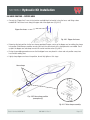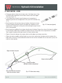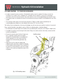
1
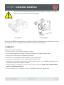
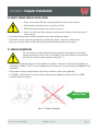
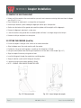
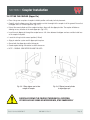
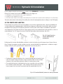
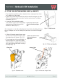
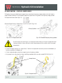
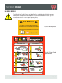
COUPLER
C2
Series
Installation Manual
902-001-31 Rev 1 TWO LINE – DUAL SWITCH
THE WEDGELOCK I-LOCK™ COUPLER RANGE COMPLIES WITH AS4772-2008
SPECIAL NOTE
Your new Wedgelock Coupler is fitted with the I-LOCK™ Safety System. This requires the installation of an I-Lock
Control Valve and Switch – please follow the instructions carefully.
72 Montgomery Crescent
Upper Hutt 5018, New Zealand
ph: +64 4 526 3901
www.wedgelock.com
Parts & Service 01/02/2015
902-001-31 Rev 1
Page 1
Coupler
INSTALLATION REFERENCE GUIDE
1
Remove Bucket if attached to the excavator dipper arm. (8)*.
2
Install Quick Coupler using the carrier machine’s original dipper and linkage pins
(8,9)*.
3
Once mounted, rotate coupler through its full range of movement and check clearances around coupler and dipper arm (9)*.
4
Begin routing hoses from coupler to the dipper manifold on the dipper arm to determine house routing and dipper manifold positioning (10,11)*.
5
Position dipper arm hoses, install hose clamps and connect hoses to dipper manifold as labelled (15)*.
6
Position boom hoses, install hose clamps and join unions. Ensure all moving joints
are fitted with abrasive sleeve (16)*.
7
After hose routing is completed, it will be easy to determine the best/final mounting
location for the coupler control valve (13,17)*.
8
Route hoses form valve ports to hoses on boom and join with unions (17)*.
9
Locate and connect pressure line from test port on pump to “P” port on valve (17)*.
10
Locate and connect hose from tank to return line to “T” port on valve (17)*.
11
Route Tilt Coupler function auxiliary hoses (18)*.
12
Locate mounting position for I-LOCK control switches in cab (19)*.
13
Route electrical harness from din connectors on valve to switch harness and attach
positive and negative leads (19)*.
14
Check circuit pressures (21)* and test coupler function to ensure system is working
properly (refer to Operators Manual)
*Refers to Installation Manual page reference
Page 2
902-001-31 Rev 1
Parts & Service 01/02/2015
CONTENTS
REFERENCE CARD. . . . . . . . . . . . . . . . . . . . . . . . . . . . . . . . . . . . . . . . . . . . . . . . . . . . . . . . . . . . . . . . . . . . . . . . 2
CONTENTS . . . . . . . . . . . . . . . . . . . . . . . . . . . . . . . . . . . . . . . . . . . . . . . . . . . . . . . . . . . . . . . . . . . . . . . . . . . . . 3
INTRODUCTION. . . . . . . . . . . . . . . . . . . . . . . . . . . . . . . . . . . . . . . . . . . . . . . . . . . . . . . . . . . . . . . . . . . . . . . . . . 4
SECTION 1: INSTALLATION GUIDE LINES
1.0 CHECK LIST. . . . . . . . . . . . . . . . . . . . . . . . . . . . . . . . . . . . . . . . . . . . . . . . . . . . . . 5
SECTION 2: PRECAUTIONS
2.0 SAFETY PRECAUTIONS. . . . . . . . . . . . . . . . . . . . . . . . . . . . . . . . . . . . . . . . . . . . . . 6
2.1 WELDING PRECAUTIONS. . . . . . . . . . . . . . . . . . . . . . . . . . . . . . . . . . . . . . . . . . . . . 6
SECTION 3: COUPLER INSTALLATION
3.0 SAFETY DURING COUPLER INSTALLATION. . . . . . . . . . . . . . . . . . . . . . . . . . . . . . . . 7
3.1 COUPLER ORIENTATION . . . . . . . . . . . . . . . . . . . . . . . . . . . . . . . . . . . . . . . . . . . . . 7
3.2 REMOVE THE EXISTING BUCKET. . . . . . . . . . . . . . . . . . . . . . . . . . . . . . . . . . . . . . . 8
3.3 FITTING THE COUPLER (LINK PIN) . . . . . . . . . . . . . . . . . . . . . . . . . . . . . . . . . . . . . . 8
3.4 FITTING THE COUPLER (DIPPER PIN). . . . . . . . . . . . . . . . . . . . . . . . . . . . . . . . . . . . 9
SECTION 4: HYDRAULIC KIT INSTALLATION
4.0 THE JUMPER HOSE JUNCTION . . . . . . . . . . . . . . . . . . . . . . . . . . . . . . . . . . . . . . . 10
4.1 FITTING THE JUNCTION MANIFOLD BLOCK . . . . . . . . . . . . . . . . . . . . . . . . . . . . . . 11
4.2 THE I-LOCK CONTROL VALVE . . . . . . . . . . . . . . . . . . . . . . . . . . . . . . . . . . . . . . . . 12
4.3 INSTALLING THE CONTROL VALVE. . . . . . . . . . . . . . . . . . . . . . . . . . . . . . . . . . . . . 13
4.4 HOSE ROUTING . . . . . . . . . . . . . . . . . . . . . . . . . . . . . . . . . . . . . . . . . . . . . . . . . . 13
4.5 HOSE ROUTING – COUPLER JUMPER HOSES. . . . . . . . . . . . . . . . . . . . . . . . . . . . . 14
4.6 HOSE ROUTING – DIPPER ARM. . . . . . . . . . . . . . . . . . . . . . . . . . . . . . . . . . . . . . . 15
4.7 HOSE ROUTING – BOOM. . . . . . . . . . . . . . . . . . . . . . . . . . . . . . . . . . . . . . . . . . . . 16
4.8 HOSE ROUTING – BOOM TO VALVE. . . . . . . . . . . . . . . . . . . . . . . . . . . . . . . . . . . . 17
4.9 HOSE ROUTING – VALVE TO PUMP / TANK. . . . . . . . . . . . . . . . . . . . . . . . . . . . . . . 17
4.10 HOSE ROUTING – TILT COUPLER AUXILIARIES . . . . . . . . . . . . . . . . . . . . . . . . . . . 18
SECTION 5: ELECTRICAL INSTALLATION
5.0 ELECTRICAL INSTALLATION. . . . . . . . . . . . . . . . . . . . . . . . . . . . . . . . . . . . . . . . . 19
SECTION 6: ASSEMBLIES 6.0 LOOSE HOSE KIT ASSEMBLY. . . . . . . . . . . . . . . . . . . . . . . . . . . . . . . . . . . . . . . . . 20
6.1 PRE-CRIMPED HOSE KIT ASSEMBLY . . . . . . . . . . . . . . . . . . . . . . . . . . . . . . . . . . . 20
SECTION 7: FINISH & TEST. . . . . . . . . . . . . . . . . . . . . . . . . . . . . . . . . . . . . . . . . . . . . . . . . . . . . . . . . . . . . . . . . . .
7.0 FINISH & TEST. . . . . . . . . . . . . . . . . . . . . . . . . . . . . . . . . . . . . . . . . . . . . . . . . . . 21
7.1 FINAL ASSEMBLY. . . . . . . . . . . . . . . . . . . . . . . . . . . . . . . . . . . . . . . . . . . . . . . . . 22
SECTION 8: DECALS
8.0 IN CAB DECALS. . . . . . . . . . . . . . . . . . . . . . . . . . . . . . . . . . . . . . . . . . . . . . . . . . 23
SECTION 9: CHARTS
9.0 TORQUE CHART – METRIC BOLTS. . . . . . . . . . . . . . . . . . . . . . . . . . . . . . . . . . . . . 24
9.1 TORQUE CHART – JIC CONNECTIONS. . . . . . . . . . . . . . . . . . . . . . . . . . . . . . . . . . 24
9.2 PRESSURE SETTING CHART . . . . . . . . . . . . . . . . . . . . . . . . . . . . . . . . . . . . . . . . . 24
SECTION 10: ROTARY ACTUATOR INFORMATION
10.0 TECHNICAL DATA. . . . . . . . . . . . . . . . . . . . . . . . . . . . . . . . . . . . . . . . . . . . . . . . 25
10.1 PRESSURE & FLOWS . . . . . . . . . . . . . . . . . . . . . . . . . . . . . . . . . . . . . . . . . . . . . 25
SECTION 11: APPENDICES
11.0 APPENDICES SCHEDULE. . . . . . . . . . . . . . . . . . . . . . . . . . . . . . . . . . . . . . . . . . . 26
Parts & Service 01/02/2015
902-001-31 Rev 1
Page 3
INTRODUCTION
OUR FOCUS IS….
THE OPERATOR, because operators and their co-workers deserve safer work sites
OUR PURPOSE....
Transforming the world’s excavators into highly productive, safe and user-friendly tool carriers.
OUR VALUES….
PIONEERING, we are continually pushing in new directions. We are building a reputation as the industry
innovators through constantly looking for ways to make excavator operators’ lives better. And we look to new
opportunities in new markets, reaching customers that others don’t.
COMMITTED – we are committed to our customers, our people, our community and New Zealand. We are
committed to the cause of simple, user-centric design and we are committed to safety, without compromise.
COLLABORATIVE – we maximize the value we add to our customers’ business by working in active,
collaborative partnerships. We are onside: we take time to listen, we encourage honest dialogue, we look for
opportunities on their behalf, we think proactively as well as responsively.
COURAGEOUS – we are bold and intrepid in our quest for earth-moving innovation. We do not turn back at
the first hurdle. We are determined (the earth wasn’t moved in a day!) Our attitude is robust and our product
testing rigorous. We honour the Kiwi pioneering spirit and are proud to uphold it.
FAMILY – we believe people need to be treated as they are family. We look to build long-term relationships
both internally and externally through an honest, down-to-earth approach. We believe business success is
crucial – but not at the expense of people.
OUR MISSION….
CREATING HUMAN ATTACHMENTS
A business that builds stronger, more enduring human relationships
A business that creates uniquely user-centric products
The Wedgelock Quick Coupler was originally developed by Graham Calvert at Waikanae Engineering, NZ, in 1987.
The company and its reputation have since grown into a global leader in the design, manufacture and distribution of
excavator attachments.
Over the years Wedgelock has developed a complete range of excavator attachments to cater for machines from one
tonne to 100 tonne. Spearheading the range is the I-Lock Coupler.
Changes in safety standards and a continuous commitment to product improvement has resulted in the development
of the I-Lock Coupler, a world first in coupler safety. The I-Lock Coupler incorporates the unique patented I-Lock Safety
Knuckle, a differentiated safety feature that is first on and last off, eliminating the high risk of dropping an attachment
during change over.
Page 4
902-001-31 Rev 1
Parts & Service 01/02/2015
SECTION 1: Installation Guidelines
This manual contains information relating to the installation of both the standard I-Lock Coupler
and the I-Lock Tilt Coupler manufactured by Wedgelock.
I-Lock Coupler
I-Lock Tilt Coupler
Please read this MANUAL thoroughly before you commence installation. Deviating from these instructions may result in
increased install time and / or damage to the hydraulic kit, carrier machine or attachment.
1.0 CHECK LIST
Before you start check the following
• Check the contents of the installation components supplied.
• Ensure that the components are correct for the carrier machine that the coupler is to be installed.
• Check that the carrier machine is positioned on level ground.
• Check that you have absorbent materials available to soak up any fluid spills.
• Dispose of any used materials in a safe and environment friendly manner.
• Power off the carrier machine. If the machine has been working ensure that it has cooled down adequately prior to
commencing any part of the installation procedure.
• Before carrying out any welding on the carrier machine disconnect the battery. Refer to the carrier machine
operator / maintenance manual.
• Ensure that the pressure in the hydraulic system is relieved before opening any hydraulic lines.
Parts & Service 01/02/2015
902-001-31 Rev 1
Page 5
SECTION 2: Precautions
Please ensure you follow the stated precautions below whilst carrying out the coupler and hydraulic kit
installation procedure.
2.0 SAFETY PRECAUTIONS
Always use PPE (Personal Protective Equipment) when servicing, operating or maintaining plant, machinery and its
components.
Refer to the carrier machine “Service Manual” for correct procedures when carrying out work on the machine. The
machine service manual takes precedence over any discrepancies between that and this installation manual.
Allow for hydraulic oil to cool adequately before opening or accessing any hydraulic lines. Hydraulic lines, fittings and
components can be hot which can be harmful causing severe burns.
Relieve the hydraulic tank pressure before accessing hydraulic lines. Refer to the carrier machine service manual for
proper procedures.
Ensure that the stick of the carrier machine is resting on the ground at all times – do not leave attachments suspended
in the air during service / installation.
Check and tighten all fittings, hose connections and joints within the hydraulic quick coupler circuit prior to activating
the machine.
Visually inspect for oil leaks tighten and adjust accordingly. Avoid contact with hydraulic fluids and high pressure oils –
use cardboard or similar as a backing when checking for leaks.
Oil spills are sometimes unavoidable. Contain all fluid spills with appropriate absorbent materials and dispose
accordingly. Immediately clean affected areas to minimize safety risks.
When operating plant and machinery keep people and property well out of harms way. Evaluate the working
environment and identify hazards. Ensure that all people involved in the installation understand the hazards associated
with this procedure.
2.1 WELDING PRECAUTIONS
Before commencing any welding procedures on the carrier machine ensure that the engine is turned off and the
battery supply is disconnected (refer to the carrier machine service manual)
Ensure all surrounding areas are protected with a flame resistant covering. Clear surrounding areas of combustible
materials. Ensure you have a fire extinguisher at hand.
Cover highly susceptible surfaces like cylinder rods, glass windows, electrical components and plastics to prevent
spatter or heat damage.
Connect the ground cable (earth lead) from the welder to the component to be welded to the carrier machine.
Ensure parts and surfaces to be welded are clean and prepared properly for welding.
Use appropriate PPE (Personal Protective Equipment) when carrying out any welding procedures.
Page 6
902-001-31 Rev 1
Parts & Service 01/02/2015
SECTION 3: Coupler Installation
3.0 SAFETY DURING COUPLER INSTALLATION
• Always use the correct PPE when removing attachments from carrier machines.
• Stand well clear of machinery that is in motion at all times.
• NEVER place hands or fingers near pin holes or recesses.
• Always use correct tools when carrying out removal and installation of attachments on the
carrier machine.
• Use correct lifting techniques and lifting equipment when maneuvering heavy objects
• Attachments may roll or tip during removal when placed on the ground – place with extreme caution
• Always use assistance when installing and removing attachments pinned to the carrier machine
3.1 COUPLER ORIENTATION
The I-Lock Coupler has been designed and manufactured to fit the dipper arm and linkage
assembly of the carrier machine. The I-Lock Coupler fits the carrier machine in one orientation
only with the C-Section facing the operators view (Fig 3.1.1)
• Always use the original bucket pins to fit the coupler to the machine. These pins are designed for the dipper arm
and linkage assemblies. DO NOT use non-hardened (soft) attachment pins. If unsure consult your Wedgelock Dealer
immediately.
• Always replace o’rings to original positions and utilize pin retention systems where applicable.
• If a THUMB is / will be fitted to the carrier machine utilizing the main dipper pin position refer to the THUMB
Installation Guide for reference.
Operator View
Fig. 3.1.1 Coupler Orientation
Parts & Service 01/02/2015
902-001-31 Rev 1
Page 7
SECTION 3: Coupler Installation
3.2 REMOVE THE EXISTING BUCKET
• Before you fit the coupler to the carrier machine you may have to remove an existing attachment from the dipper
arm. (Fig 3.2.1). If so…..
• Place the bucket or attachment in a safe position on the ground.
• Undo the pin retention systems holding the dipper pin and link pin in their position.
• Gentle raise the bucket off the ground and crowd the cylinder until the weight is off the dipper pin.
• Remove the dipper pin and place in a clean area.
• Lower the bucket to the ground with the crowd cylinder until there is no longer weight on the link pin.
• Remove the link pin and place in a clean place.
3.3 FITTING THE COUPLER (Link Pin)
• Ensure the coupler is sitting on a flat surface in the correct orientation.
• Align the dipper arm of the carrier machine with the coupler.
• Position the o’rings for the linkage boss assembly on the linkage boss (if fitted).
• Using the crowd cylinder lower the linkage into position on the rear boss of the coupler (Fig 3.3.1)
• Align the coupler if necessary using a bar or lever.
• Insert the linkage pin through the coupler boss and linkage boss.
• Align pin retention system and fix linkage pin into place.
• Locate the o’rings into the correct position (if fitted).
• NOTE – ORIGINAL OEM LINKAGE PIN MUST BE USED.
Fig. 3.2.1 Remove bucket
Page 8
Fig. 3.3.1 Lower linkage into coupler
902-001-31 Rev 1
Parts & Service 01/02/2015
SECTION 3: Coupler Installation
3.4 FITTING THE COUPLER (Dipper Pin)
• Place o’rings over ear plates of coupler to hold in position until ready for final placement.
• Carefully raise the dipper arm of the carrier machine so that the weight of the coupler is off the ground. Ensure that
the dipper arm is in a vertical position. (Fig 3.4.1).
• Retract the crowd cylinder until the coupler front boss aligns with the dipper pin hole. The coupler will balance
allowing an easy insertion of the main dipper pin. (Fig 3.4.2).
• Insert the main dipper pin through the coupler bosses & fit shims between the dipper arm boss and the inside face
of the coupler if required.
• Locate the o’rings into the correct position (if fitted).
• Align pin retention system and fix dipper pin into place.
• Grease both the dipper pin and the linkage pin.
• Crowd coupler through full rotation to check clearances.
• NOTE – ORIGINAL OEM DIPPER PIN MUST BE USED.
Fig. 3.4.1 Raise dipper arm to take
weight off coupler
Fig. 3.4.2 Retract crowd cylinder
to align dipper pin
CAREFULLY CROWD THE COUPLER THROUGH FULL ROTATION.
IF THERE ARE ANY SIGNS OF INTERFERENCE, STOP IMMEDIATELY
Parts & Service 01/02/2015
902-001-31 Rev 1
Page 9
SECTION 4: Hydraulic Kit Installation
For the coupler function there are three main sections to the HYDRAULIC kit installation:
Fitting of the Jumper Hose Junction Block (or bracket) to the dipper arm.
1. Installing the I-Lock Control Valve in the engine compartment.
2. Routing the 2 line hydraulic hose circuit
3. The fourth section relates to the routing of the auxiliary lines for the tilt motor operation (when installing an I-Lock Tilt Coupler).
The fourth section relates to the routing of the auxiliary lines for the tilt motor operation (when installing an I-Lock Tilt Coupler).
4.0 THE JUMPER HOSE JUNCTION
For the jumper hose junction at the base of the dipper arm you will be supplied with either a 6 port manifold block or
a 4 hole angle bracket (model dependant). Utilizing these components will provide the installer the ability to achieve
the optimum hose routing for the hydraulic jumper lines from this point to the coupler. Two additional 3 port blocks
are included with a Tilt Coupler install kit on larger couplers which can be combined with the 6 port block as shown or
used individually. The “W” Logo on the front of the 6 Port Block defines block orientation. (Fig 4.0.1)
Fig. 4.0.1 Angle Bracket or
Junction Manifold Block
configuration
Positioning of the Junction Manifold Block or bracket is critical to the life cycle of the jumper hoses. Reverse Hose or
Direct Through Hose options are both available using the Junction Manifold. The angle bracket is suitable for straight
through routing only and is generally better suited to mini excavators.(Fig 4.0.2)
• To determine the optimum position of the Junction Manifold Block (or bracket) firstly
rotate the coupler through full rotation using the crowd cylinder to check available
clearances for the manifold (or bracket) at both full stroke and zero stroke.
• The manifold (or bracket) should be placed as close as possible to the main dipper
pin to minimize jumper hose length – when utilizing universal jumper hose kits any
excess jumper hose can be then contained inside the coupler body. (Fig 4.0.3)
Fig. 4.0.3 Junction Manifold position as low as practicable
Page 10
902-001-31 Rev 1
Parts & Service 01/02/2015
SECTION 4: Hydraulic Kit Installation
4.1 FITTING THE JUNCTION MANIFOLD BLOCK (or BRACKET)
• Once the optimum position has been determined, clean and prepare the surface
of the dipper arm to be welded.
• Lightly tack the manifold (or bracket) into position, carefully tacking only the ends.
(Refer to welding precautions and carrier machine service manual for welding
instructions) (Fig 4.1.1).
• If using the 3 piece manifold assembly
stitch weld the 3 parts of the manifold block Lightly tack weld on ends
when positioning on dipper
together before fitting to the arm of the
arm
machine as above. (Fig 4.1.2)
The 3 components can also be used independent of each other (ie welding the 6 port
block on the dipper arm face and welding the 3 port blocks to the side of the dipper
arms)
Fig. 4.1.1 Weld location
• If fitting a tilt coupler remove the rear cover
for easy access to the port locations where
the jumper hoses will connect. (Fig 4.1.3)
Lightly tack weld on ends
when positioning on
• Fit one jumper hose to the manifold block (or dipper arm
bracket) and rout this to the main cylinder
(when installing a standard coupler Fig 4.5.3)
or the bulk head manifold (when installing a
tilt coupler Fig 4.1.4)
Cover plate
Fig. 4.1.2 Stitch weld together
Jumper Hose
Fig. 4.1.3 Remove cover
Parts & Service 01/02/2015
Fig. 4.1.4 Rout one Jumper Hose
902-001-31 Rev 1
Page 11
SECTION 4: Hydraulic Kit Installation
• Crowd coupler SLOWLY through full rotation checking that the hose can move freely and is not subject to pinching
or crushing at any point. Re-position manifold if required.
• Remove jumper hose, stitch weld the ends ONLY of the manifold block (or bracket) to the dipper arm. (Fig 4.1.5)
• Touch up paint finish on welded component to match carrier machine colour.
Fig. 4.1.4 Stitch weld
each end to dipper
4.2 THE I-LOCK CONTROL VALVE
The I-Lock Coupler is designed to operate on the carrier machine’s MAINS PRESSURE supply.
The I-Lock Control Valve regulates the oil pressure and oil flow and controls the oil direction within
the coupler hydraulic circuit. The Control Valve supplied MUST BE USED for any installation of an
I-Lock Coupler.
• The control valve has distinguishable markings to assist with the electrical connection and hose routing to ensure
that the coupler operates in accordance with which it has been designed. The Control Valve is also fitted with Twin
Solenoids. One for the wedge retraction and one for the wedge extension. (Fig 4.2.1). The markings on the control
valve for the hydraulic hose connections are as follows.
P – Pump pressure in
T – Tank return
R – Retract Primary Wedge
E – Extend Primary Wedge
PRV
Twin Solenoids
Check valve
Hose ports
Fig. 4.2.1 I-Lock Control Valve
• For pressure settings refer to Section 9.2 Pressure Settings Chart.
• For service details regarding the control valve refer to the service section in the Operators Manual.
Page 12
902-001-31 Rev 1
Parts & Service 01/02/2015
SECTION 4: Hydraulic Kit Installation
4.3 INSTALLING THE CONTROL VALVE
• Identify the PUMP that delivers flow to the CROWD CYLINDER of the carrier machine. This is the most common
pump used for hydraulic couplers operating on mains pressure (refer to the carrier machine service manual if
required).
• Utilizing the mounting plate supplied determine a suitable location in the pump / engine
compartment of the carrier machine to mount the control valve. The mounting plate can
either be welded or bolted into position. (Fig 4.3.1)
• Bolt the Control Valve to the mounting plate with the bolts provided.
NOTE: The best position for mounting of the control valve may be determined after the
hose routing from the boom to the pump compartment. Check where the hoses exit from
the boom end in the pump compartment before mounting the valve as the I-Lock hoses
will invariably follow this same route.
Fig. 4.3.1 Mounting plate
4.4 HOSE ROUTING
Wedgelock Hose Kits have been designed to improve the speed and ease in which an installer
can fit the hydraulic kit. The content of the hydraulic hose kit has been pre determined to ensure
that, in most cases, the majority of fittings required to complete the install are provided. In some
circumstances additional fittings may have to be sourced to complete the connection to the pump
test port and tank return. For information regarding the port type at these locations please refer to
the carrier machine service manual.
The “Pre Crimped” Wedgelock hose kits are colour coded with coloured cable ties at each end of the pre crimped
hoses. Following the Installation Reference Card will assist with identifying each of the hoses to be routed in respect to
their relative positions on the carrier machine. Once the manifold block and solenoid control valve are in position it is
advisable to begin routing the hoses from the coupler end of the machine to the engine compartment end.
If using a “Pre-Crimped” Hose Kit follow the instructions ensuring that each colour coded hose is positioned as
required. If using a ‘Loose Fitting Kit” you can use the colour coded instructions as a guide to achieve the same results.
(see Section 6 Assemblies)
When installing a Tilt Coupler the auxiliary hoses required for the “Tilt Motor” operation are not
provided for in the standard Wedgelock Hydraulic Kit. Due to the vast array of carrier machine
configurations in relation to auxiliary circuits you must refer to the carrier machine manual to
understand what auxiliary configuration your machine has. (see section 4.10 Hose Routing Tilt
Coupler to Auxiliaries)
Only trained and qualified hydraulic installers should configure the carrier machine to operate the Tilt Coupler Motor.
The fitting of the 3 Port Junction Manifold Blocks for the jumper hoses for the “Tilt” function are a suggested solution
for this part of the install only and DO NOT have to be used (see section 4.1 Fitting the Junction Manifold Block).
Wedgelock however takes no responsibility for the quality of and the result of the installation carried out by any third
party in relation to this product.
Parts & Service 01/02/2015
902-001-31 Rev 1
Page 13
SECTION 4: Hydraulic Kit Installation
4.5 HOSE ROUTING – COUPLER JUMPER HOSES
Tilt Couplers have pre installed internal coupler hoses connecting the primary wedge cylinder to the bulk head to
simplify infield installation On the Standard Coupler the jumper hoses will go direct to the primary wedge cylinder
Tilt Coupler Bulk Head: (Refer Fig 4.5.1). A1 = Extend
A2 = Retract
P1 = Tilt Right
P2 = Tilt Left
Standard Coupler Primary Cylinder Ports: E or EXT & R or RET (Fig 4.5.2)
Primary Cylinder
Fig. 4.5.1 Tilt Coupler bulk head
Fig. 4.5.2 Standard Coupler primary cylinder
You will need to note which hoses are connected to which fittings on the quick coupler bulk head
/ primary cylinder as these will have to match the port options on the control valve in the engine
compartment.
• On the Tilt Coupler connect the “Jumper Hoses” from the tilt coupler bulk head to the junction manifold block (or
bracket) mounted on the dipper arm.
• On the standard coupler connect the jumper hoses to the primary cylinder.
• Use jumper hoses, nylon abrasion sleeve and fittings provided which are colour coded YELLOW. (Fig 4.5.3)
Jumper hoses
Fig. 4.5.3 Jumper hoses
Page 14
902-001-31 Rev 1
Parts & Service 01/02/2015
SECTION 4: Hydraulic Kit Installation
4.6 HOSE ROUTING – DIPPER ARM
• Connect the “Dipper Arm” hoses to the junction manifold block (or bracket) using the hoses and fittings colour
coded BLUE. Rout these hoses along the upper side of the dipper arm. (Fig 4.6.1)
Dipper Arm hoses
Fig. 4.6.1 Dipper Arm hoses
• Determine the best position for the hose clamps provided. Prepare surface of the dipper arm for welding the clamps
into position. Weld clamp assemblies ensuring that only the vertical ends of the clamp brackets are welded. Touch
up paint the dipper arm and clamp to match the carrier machine colour. (Fig 4.6.2)
• During clamp welding procedure ensure that the dipper hoses are placed in a clean and safe position away from
heat and the welding area.
• Lightly clamp dipper arm hoses into position, do not fully tighten at this stage.
Hose clamps
Fig. 4.6.2 Hose clamp position
(example only)
Fig. 4.5.2 Hose clamp assembly
Parts & Service 01/02/2015
902-001-31 Rev 1
Page 15
SECTION 4: Hydraulic Kit Installation
4.7 HOSE ROUTING – BOOM
• Fit the nylon abrasive sleeve over the loose ends of the Dipper hoses. Using
the GREEN colour coded hoses for the Boom, connect these to the dipper
arm hoses. (Fig 4.7.1)
• Lay the Boom hoses along the top of the boom arm in preparation of
determining the best hose clamp position for this part of the installation. (Fig
4.7.2)
• Mark the position of the top hose clamp on the boom, allowing for the hose
to follow the boom movement relative to the dipper arm movement on the
top pivot point. Following the existing hose route and length through this pivot
area is recommended.
Fig. 4.7.1 Hose joint (typical)
• Mark the position of additional hose clamps along the top of the boom. Prepare the surface of the boom for welding
in these locations. Weld clamp assemblies ensuring that only the vertical ends of the clamp brackets are welded.
Touch up paint the boom and clamp to match the carrier machine colour.
• Tighten all hose joints between the coupler cylinder and the dipper arm to boom connections.
• Tighten the clamp assemblies, pulling through any excess hose, working from the dipper end to the bottom of the
boom. Allow “hose slack” for pivot movement and ensure that the hose assemblies are not stressed in any way. Use
cable ties where required.
Dipper to boom hose joint
Boom to Valve hose joint
Clamp assemblies
(Multiple locations along boom)
Hose slack for pivot movement
(with nylon abrasive sleeve)
Page 16
Fig. 4.7.2 Boom hose routing
902-001-31 Rev 1
Parts & Service 01/02/2015
SECTION 4: Hydraulic Kit Installation
4.8 HOSE ROUTING – BOOM TO VALVE
• Connect the RED colour coded hoses for the Boom to Valve to the boom hoses at the base end of the boom.
• Rout the hoses through to the pump compartment towards the control valve following the existing hose routing
from the boom end.
• Trace the hoses from the quick coupler cylinder right through to the end where they connect to the valve to
determine the correct hose for each port position on the valve.
• Connect the hose ends to the control valve ensuring that they are connected to their respective port positions
relative to the cylinder.
• Cable tie Boom to Valve hoses to existing hoses where appropriate and coil any excess hose in the pump
compartment. Ensure that the hoses are not bound up or under any strain.
• Tighten all hose joints and fittings between the lower boom end and the control valve.
4.9 HOSE ROUTING – VALVE TO PUMP & TANK
• Using the BLACK colour coded hoses from the install kit connect the hose ends to the valve marked P (Pump) and T
(Tank).
• Utilizing a “TEST PORT” on the pump that delivers hydraulic pressure to the crowd cylinder connect the hose from
the “P” port to the test port. (see section 4.3 Installing the Control Valve)
• Locate an existing “RETURN” hose on the main return manifold or hydraulic tank. Disconnect the existing hose and
install a tee fitting.
• Reinstall the existing hose onto one end of the tee and then connect the new return hose from the control valve “T
port to the other end of the tee.
• Cable tie hoses to existing hoses where appropriate and coil any excess hose if required. Ensure that the hoses are
not bound up or under any strain.
• Tighten all hose joints and fittings between the control valve and the pump and tank.
NOTE 1: When utilizing a “Pre Crimped” or “Loose” hose kit supplied by Wedgelock we have endeavoured to supply
the majority of the fittings required to carry out a complete install of an I-Lock Coupler, however due to the vast array of
different carrier machines, fitting types and port sizes, not all circumstances may be accounted for. In instances where
the fittings supplied do not match the port size or the type of carrier machine that this install is being carried out on
please contact your nearest machinery dealer or hydraulic fittings provider for the additional appropriate component(s).
NOTE 2: See section 6 Assemblies.
Parts & Service 01/02/2015
902-001-31 Rev 1
Page 17
SECTION 4: Hydraulic Kit Installation
4.10 HOSE ROUTING – TILT COUPLER AUXILIARIES
• In order to connect the rotary actuator, a 2nd hydraulic auxiliary circuit is needed. If this does not exist, the
installation of an auxiliary circuit complete with a solenoid valve for activation is necessary. For operating
instructions refer to the service manual of the carrier machine as this will vary depending on the machine setup.
• The hydraulic ports are located on the top of the actuator but may be pre-hosed to a manifold block at rear of the
coupler.
• The maximum working pressure for the Rotary Actuator is 210 bar. In order to work economically, the
recommended pump capacity must be followed. (See section 10.1 Pressure & Flow)
The Auxiliary Circuit configuration at the base of the dipper arm will vary from one machine to another. If using the 3
Piece Junction Manifold as described in section 4.0 then the following points should be followed.
• Pre-determine the overall length of the Auxiliary hoses by following the same path as the Coupler Jumper Hoses.
• Assemble the auxiliary hose ensuring that the correct fittings are used to connect to the rotary actuator and the
junction manifold block.
• Connect the tank line hose first then the pressure
line as required. Carefully rotate the coupler
through the full crowd rotation. A second person
will be required to assist to visually check the
movement of the hoses during operation. (Fig
4.10.2)
Auxilliary hoses
• Adjust the lay of the hoses by undoing and
retightening the connections to obtain the desired
hose movement during rotation. Hoses should NOT
be under any tension during any part of the crowd
rotation as this could cause premature wear of this
component.
Fig. 4.10.2 Auxilliary hoses
Page 18
902-001-31 Rev 1
Parts & Service 01/02/2015
SECTION 5: Electrical Installation
5.0 ELECTRICAL INSTALLATION
The I-Lock Coupler is sold with the proprietary electrical install kit. This kit consists of an I-LOCK
CONTROLLER, an IN CAB SWITCH ASSEMBLY and a SOLENOID LOOM. These components have
been designed in conjunction with the functionality and operation of the coupler safety features.
The built in ‘Timer” and “Operational Sequences” controlling the solenoid valve are features which
provide the operator and fellow co-workers a safe work environment during attachment change over.
Failure to utilize the proprietary electrical components with the I-Lock Coupler could result in coupler malfunction,
causing serious harm or even death. (Fig 5.0.1 & 5.0.2 & 5.0.3)
Fig. 5.0.1 Dual Switch Assembly
Fig. 5.0.2 I-Lock Controller
Fig. 5.0.3 Solenoid Loom
• The I-Lock Controller, Switch Assembly and Solenoid Loom are designed to enable a “plug & play” electrical
installation process.
• Determine a suitable position for the I-Lock Controller. Ensure the position is a dry location and easily accessible.
Mount into position. (Caution - Do not over tighten fixing screws)
• Find two spare suitable locations in the machine console to insert the dual rocker switches (preferably side by side).
• Rout the switch wires to the I-Lock Controller. Connect the corresponding fittings.
• Locate a switched (fused) power source from within the console of the carrier machine. Connect the RED power
lead on the Lockout Switch to the power source.
• Find a suitable earth location (negative) and connect the BLACK wire from the
I-Lock Controller.
• Plug the Solenoid Loom into the I-Lock Controller.
• Rout the Solenoid Loom from the I-Lock Controller position through to the engine
compartment where the Control Valve is located.
• Connect the RED labeled DIN Plug to the EXTEND (E) solenoid.
• Connect the BLACK labeled DIN Plug to the RETRACT(R) solenoid.
NOTE: The (E) solenoid is aligned with the (E) Port and the (R) solenoid
is aligned with the (R) port. (Fig 5.0.4)
• Fix all electrical looms using cable ties where required.
Fig. 5.0.4
NOTE: See section 11 Appendices.
Parts & Service 01/02/2015
902-001-31 Rev 1
Page 19
SECTION 6: Assemblies
6.0 LOOSE HOSE KIT ASSEMBLY
Jumper Hoses
MANIFOLD
or
BRACKET
I-LOCK
COUPLER
Dipper Arm Hoses
Pump & Tank Hoses
Boom Hoses
MACHINE
SPECIFIC
FITTINGS
CONTROL
VALVE
Fig. 6.0.1 Loose Hose Kit Assembly
6.1 PRE-CRIMPED HOSE KIT ASSEMBLY
Jumper Hoses
I-LOCK
COUPLER
MANIFOLD
or
BRACKET
Dipper Arm Hoses
Pump & Tank Hoses
CONTROL
VALVE
MACHINE
SPECIFIC
FITTINGS
Boom Hoses
Fig. 6.1.1 Pre-crimped Hose Kit Assembly
Page 20
902-001-31 Rev 1
Parts & Service 01/02/2015
SECTION 7: Finish & Test
7.0 FINISH & TEST
Before starting this section, position the machine in the “Oil Level Check” position as suggested
by the excavator machine manufacturer. Check the oil level sight gauge on the hydraulic tank. Add
hydraulic oil if necessary (refer to the carrier machine service manual for further information).
• Check the hose clamp assemblies and valve mounting bolts are tightened to the recommended torque. Refer
section 9 Charts.
• Starting at the coupler end thoroughly check that the hose connections are tightened through out the complete
circuit to the recommended torque. Refer section 9 Charts.
• Clear all personnel and all obstacles from the swing radius area and working parameter of the machine.
• From the seat of the excavator, start the machine and lower the excavator arm to near the ground. In a very slow
motion, using the excavator levers, raise the dipper arm and crowd the coupler through full rotation. Then raise the
boom of the excavator and motion the dipper arm cylinder to full extension. Now motion the dipper arm cylinder to
full retraction, lowering the boom arm in unison.
• TESTING THE TILT FUNCTION ON THE TILT COUPLER – Position the coupler slightly off the ground to prepare
to test the functionality of the rotary actuator. Using the auxiliary controls motion the rotary actuator of the tilt
coupler to the left hand side until the actuator dead ends against the mechanical stops. Now change direction and
rotate the unit through full rotation to the right until it dead ends on the opposing stops. Do this several times to
ensure that the actuator is working properly.
• Use the above processes to check the hose routing throughout the complete circuit. Ensure that the hoses are not
under any strain or subject to potential jamming or pinching. Assistance will be required to do this. Modify hose
routing if required.
• Running the machine at idle or a low engine RPM setting to supply a low volume of oil through the circuit. Activate
the circuit and check for any leaks. Shut down the machine immediately if leaks are detected, then tighten as
required and re-check.
• Check circuit pressures and bleed lines if necessary. Refer section 9 Charts.
• Activate the coupler circuit several times to ensure that the system is working correctly – refer to the I-Lock
Coupler Operators Manual.
Parts & Service 01/02/2015
902-001-31 Rev 1
Page 21
SECTION 7: Finish & Test
7.1 FINAL ASSEMBLY
• Once the test procedure has been completed, touch up paint any welded brackets or assemblies and cable tie any
loose hoses.
• If applicable re-fit the rear tilt coupler cover. (Fig 7.1.1)
• Affix “In Cab” Decals in a suitable location within the operators working area. (Fig 8.0.1 & 8.0.2)
Re-fit rear cover after testing
Fig. 7.1.1 Rear cover
Before using the I-Lock Coupler carefully read the I-Lock
Coupler Operator’s Manual thoroughly.
Page 22
902-001-31 Rev 1
Parts & Service 01/02/2015
SECTION 8: Decals
8.0 IN CAB DECALS
The following two “In Cab” Decals must be affixed in a suitable location within the operators
working area. For replacement decals please call your nearest Wedgelock Dealer. (Fig 8.0.1
Warning Decal & 8.0.2 I-Lock Coupler Operating Decal)
# 903-002-3
WARNING
THIS MACHINE IS FITTED WITH A QUICK COUPLER.
LENGTH OF THE DIPPER ARM HAS INCREASED.
Fig. 8.0.1 Warning Decal
ATTACHMENTS MAY HIT THE CABIN AND OR BOOM.
THE QUICK COUPLER OPERATING MANUAL MUST BE
REFERRED TO BEFORE COMMENCING OPERATION.
OPERATOR ACTION
COUPLER ACTION
ATTACH
POSITION EXCAVATOR
ALARM
ON
SLOW BEEP
DETACH
INSTANT LOCK
Fig. 8.0.2 I-Lock Coupler
Operation Decal
PRESSURE STOPPED
TIMER ON
START
ON (hold 1 sec)
FAST BEEP
POSITION REAR PIN
OFF
BUILD PRESSURE
WEDGE & KNUCKLE RETRACT
BUILD PRESSURE
SLOW BEEP
TIMER
END
AUTO RESET
903-002-12
Parts & Service 01/02/2015
LOCK WEDGE
REMOVE ATTACHMENT
TEST
FOR FULL INSTRUCTIONS REFER TO OPERATION MANUAL
902-001-31 Rev 1
Page 23
SECTION 9: Charts
9.0 TORQUE CHART – METRIC BOLTS
The following chart gives the standard torque setting of the bolts used in this hydraulic kit installation. It is important to follow the
chart when installing bolts and nuts. Failure to do so could result in premature failure, damage to components, or even serious injury.
Torque Setting of Metric Grade 8.8 Bolts & Nuts
Bolt Dia x Pitch (mm)
M6 x 1.0
M8 x 1.25
M10 x 1.5
M12 x 1.75
M14 x 2.0
M16 x 2.0
M18 x 2.5
M20 x 2.5
Nm
9.9
24.0
48.0
83.0
132.0
200.0
275.0
390.0
Note: 1Nm = 0.102kgm = 0.737 lb.ft
Lb.Ft
7.3
17.7
35.4
61.2
97.3
147.4
202.7
287.4
9.1 TORQUE CHART – JIC CONNECTIONS
JIC (SAE 37º Flare) Connections are a very common connection in fluid power applications. Both the male and female fittings have a
37º seat. The seal takes place between the male flare and the female cone seat. The thread holds the connection mechanically.
Torque Setting of JIC Connectors
Nominal Size
¼”
3/8”
½”
Dash Size
-4
-6
-8
Nm
15 – 17
27 – 30
59 - 65
Lb.Ft
10.8 – 12.5
19.6 – 22.0
45.5 – 47.8
F.F.F.T
2
1¼
1
9.2 PRESSURE SETTING CHART
The following chart shows the range of allowable pressure settings for the I-Lock Coupler Circuit.
It is highly recommended that the pressures for each function are tested and checked before the equipment is
put to use.
I-Lock Control Valve (24v or 12v)
Marking
P
T
R
E
Function
Pressure In
Tank return
Retract Primary Wedge/Safety Knuckle
Extend Primary Wedge
Pressure Range (bar)
Full System Pressure
N/A
Full System Pressure
110- 120
Pressure Range (psi)
1600 - 1740
I-Lock Primary Cylinder
Marking
R (RET)
E (EXT)
Page 24
Function
Retract Primary Wedge/Safety Knuckle
Extend Primary Wedge
Pressure Relief Valve (if fitted)
Pressure Range (bar)
Full System Pressure
110- 120
165 - 180
902-001-31 Rev 1
Pressure Range (psi)
1600 - 1740
2400 - 2600
Parts & Service 01/02/2015
SECTION 10: Rotary Actuator Information
10.0 PRESSURE & FLOW
The following chart (Fig 10.1.1) provides recommended pressure & flow information relating to the PowerTilt range of
Rotary Actuators used in the Wedgelock Tilt Coupler Product offering.
Note: all Power Tilts are equipped with factory installed integral cross port reliefs.
Coupler
Class
Actuator
Type
Max.
Operating
Pressure
Cross
Port
Relief
Pressure
bar / psi
bar / psi
Recommended
Oil Flow
l/min
Total Tilt
Angle
Holding
Torque
Tilting
Torque
Degrees
kNm
kNm
037
PT06
3-6
180
5.64
2.82
045
PT07
6-12
180
9.48
4.74
055
PT07
6-12
180
9.48
4.74
6-12
180
21.6
6.7
210 / 3000
220-230/
3200-3300
070
PT100
130
PT180
22-28
120
41.9
13.2
170
PT10
24-32
134
29.38
14.69
210
PT10
24-32
134
29.38
14.69
Parts & Service 01/02/2015
902-001-31 Rev 1
Page 25
SECTION 11: Appendices
11.0 APPENDICES SCHEDULE
DRG #
Title
910-200-13-D
Schematic, Hydraulic, 2 Line I-Lock System
910-200-9-D
Schematic, Electrical, I-lock Switch Assembly
Page 26
902-001-31 Rev 1
Parts & Service 01/02/2015
Parts & Service 01/02/2015
902-001-31 Rev 1
Page 27
IF IN DOUBT ASK!
CARTRIDGE VALVE CAVITY CONVENTION:
CHECK
VALVE
PRESSURE SOURCE
CONTROL
VALVE
SOLENOID
VALVE EXT
PILOT CHECK
VALVE
PUMP (P)
1mm ORIFICE
EXTEND
PRESSURE
REDUCING
VALVE
SET: 120 BAR
EXTEND (E)
PRESSURE RELIEF
VALVE
SET: 172 BAR
TANK (T)
RETRACT (R)
RELIEF SETTING:
BELOW 12T: 170-190BAR
ABOVE 12T: 270-290BAR
CHECK
VALVE
REV
SOLENOID
VALVE RET
DATE
AA
DRN
FIRST ISSUE
293
DATE
15/05/13
22/08/14
AA
AA
AR
AR
SAFETY INPUT: BLUE
WEDGE INPUT: RED
-
1
2
3
4
DEUTSCH
PLUG
FEMALE
MALE
1
2
3
4
FEMALE SPADE: RED
MALE SPADE: RED
5A FUSE
WEDGE
WEDGE
SAFETY
SAFETY
RED HEAT SHRINK
(+) GREEN
(-) YELLOW
(+) BROWN
(-) WHITE
CHASSIS EARTH: BLACK
1
2
1
2
POWER SUPPLY (12/24VDC): RED
WEDGE
DIN PLUG
SAFETY
DIN PLUG
DRG: 910-200-9-D
PART: 910-200-9
Phone: +64 4 526 3901
SCHEMATIC, ELECTRICAL, I-LOCK SWITCH ASSY
(116-012-024-5 / 116-012-024-9)
www.wedgelock.com
DRN CHK
ECN
WEDGE
SAFETY
FEMALE SPADE: BLUE
MALE SPADE: BLUE
CABLE COLOURS
MATCH INPUTS/OUTPUTS
I-LOCK
CONTROLLER
DESCRIPTION
APPLICABLE ASSY NUMBERS, REFER ECN
WEDGE SWITCH
(LOCK-OUT)
SAFETY SWITCH
(MOMENTARY)
IF IN DOUBT ASK!
1
0
REV
e-mail: [email protected]
REV. 1
Parts & Service 01/02/2015
902-001-31 Rev 1
Page 28