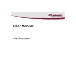
1
Operating manual
for
Automatic sprayvalve
MFS and MFS/KLS
Read this manual carefully before installing, operating or servicing this equipment.
Keep always handy for further use.
1 Introduction
The automatic spray valves MFS and MFS/KLS are designed and constructed for application of thin
materials f.i. release agents, colours or other fluids of low viscosity. Depending on air cap this spray
valve sprays in flat- or roundspray. Depending on viscosity of fluid, the application can be adjusted
individually via nozzle dimension, atomizing air pressure and material pressure. The supply of
atomizing air, control air and material should be done via three hoses. Spray valves are precision tools.
Always keep clean and observe minimum instructions to maintain a long usefull life of the valve.
2 Safety
2.1 Duties of the user
•
The user must read this service manual carefully before performing any operations.
•
Application and service operations should not be carried out if the user is not absolutely sure of
the purpose and consequence of the operations.
2.2 Definitive Use
The automatic spray valves MFS and MFS/KLS are pneumatically controlled spray valves. They are
suitable for continuously or intermittent use. They are not suitable for spraying aggressive fluids like
acid, alkaline solutions, cleaning agents, chemicals etc.. In case of doubt, please contact the
manufacturer.
2.3 Warning against danger
This operating manual warns users of operations which may put their health at risk. The warnings are
indicated by combinations of text and symbols corresponding to the different danger classes.
WARNING!
Signs a possible dangerous situation.
If you don´t avoid, death or severe injuries can follow.
CAUTION!
Indicates a situation which may be dangerous.
Failure to heed the caution may result in personal injury. This indication is also used where material
damage is possible.
IMPORTANT!
Indicates tips for usage and other helpful information.
3 Function Description
The spray valves MFS and MFS/KLS are pneumatically controlled: air open; spring return.
The spraying material is to be fed to the valves via pressure tank or pump. The separate controlled
atomizing air atomizes the material to a spray jet. Depending on mounted air cap valve sprays a flat- or
roundspray jet.
4 Installation
The MFS and MFS/KLS can be installed in any position. Vibrations of the valve caused by fast
intermitting cycles require solid and massive installation. For solid attachment the use of mounting
(9.1.0) is recommend. The hole in mounting (9.1.0) has 8mm diameter. Distance to spraying surface
varies of application. Vibration of the equipped machine to the valve should be limited as far as
possible.
4.1 Hose connection and assembly
Connect hoses for atomizing air and control air to seperatly control valves (pressure reducers and
solenoids). Then fluidhose to material pressure tank or other means of feeding fluid as under:
•
atomizing air (Z) (hose blue):
è
to 2/2 way solenoid
•
control air (S) (hose black):
è
to 3/2 way solenoid
•
fluid (M) (hose transparent):
è
to feeding device
The three hoses are fixed by the mounting (9.1.0). To assembly new hoses to the spray valve, unscrew
ratchet assembly (10.0.3). Then take off the mounting with hoses. Connect new hoses to the hose
sockets (11.1.0) and put hose sockets into the valve body (4.1.0). Assemble mounting (9.1.0) with
correct side to the valve body (4.1.0).
IMPORTANT !
Nozzle and needle can be damaged. Before adjusting ratchet assembly to the valve body,
please turn (open) regulating knob (10.1.1) anti-clockwise.
Turn (open) regulating knob anti-clockwise and screw in the ratchet assembly (10.0.3). Connect fitting
(13.0.0) for control air and fittings (13.0.1) for material and atomizing air to the hoses.
4.2 Operating instructions
CAUTION !
Never point the sprayjet against persons. Wearing eye protection is strongly recommended.
Spraying procedures cause noises depending on the used pressure. If necessary, wearing of
ear protection is recommend.
WARNING !
Danger caused by combustible and noxious spraying material. Safety instructions on fluid can
and material data of fluid manufacturer must definitely be observed.
The valves MFS and MFS/KLS need 5 – 6 bar control air pressure. The atomizing air should be 0,5 – 6
bar. To avoid hit back of material when using version MFS/KLS, the atomizing air pressure has to be
less then material pressure. The maximum material pressure in standard version is 4 bar. For higher
material pressures or using long hose length the use of mounting ¼” (9.1.1) is needed. In any case,
please observe the regulations of the professional/trade association having liability for industrial safety
and insurance.
When you are certain, that fluid pressure stands up to the nozzle, actuate 2/2 way solenoid for
atomizing air. After that actuate 3/2 way solenoid for control air. This way you reveive socalled “pre-air”
prior to opening fluid flow. After each cycle solenoids are to actuate in reverse order, so you will still
have “purging-air” after needle has closed nozzle and fluid flow was stopped. This prevent fluid to form
out drops instead of being atomized.
Set atomizing air pressure and fluid pressure according to required spray droplet sizes. Two separate
pressure reducers must be available. Intermittend use as well as continuous use is possible.
Standard version of valve has flat spray aircap (1.1.0). If round spray jet is required, install round spray
aircap (1.1.1). Flat spray aircap can be positioned for horizontal, vertical or any in between position of
jet. Depending on viscosity of fluid, nozzle diameters are available in 0,2 / 0,3 / 0,5 / 0,8 / 1,0 / 1,2 / 1,5
/ 2,0mm ∅. The travel of needle is giving way to fluid as adjusted by the regulating knob (10.1.1).
Turning this knob in anti-clockwise turn = more fluid; clockwise turn = less fluid.
One revolution of regulating knob (10.1.1) gives 0,5mm more or less stroke. Do not over-tight the
regulating knob.
IMPORTANT !
The maximum fluid outlet is already reached, when no further ratchets are noticeable. Do not
turn the regulating knob (10.1.1) in anti-clockwise turn any further.
IMPORTANT !
To avoid damages to nozzle and needle adjust decrease of fluid flow (turning regulating knob
10.1.1 clockwise) only when fluid is emitted from the nozzle. This is the only way to observe
the steady reduction of fluid flow until an absolute stop of fluid. Going on to turn the regulating
knob clockwise would at once push the needle into the nozzle to such an extant that both parts
could be damages. This applies expecially to valves where needle regulation is execute by
hexagon key (special design, not shown in sectional drawing).
It is harmless to leave fluid within the valve (no connection to outside air), if system stays under
pressure.
5 Repair and Maintance
Before starting maintenance or repair work, ensure that all air operated tools are disconnected from the
air supply.
WARNING !
Danger caused by combustible and noxious spraying material. Safety instructions on fluid can
and material data of fluid manufacturer must definitly be observed.
WARNING !
Before opening the spray valve it has to be disconnected from the air and fluid
supply. Otherwise ejected elements can cause danger.
These spray valves are high precision tools. Always keep clean and observe minimum instructions to
maintain a long and useful life of valve. We recommend lubricating moveable parts regularly, and
greasing threads, especially the nozzle threads, when replacing or cleaning the nozzle. It is
recommended to use clean and filtered application fluid only. Also atomizing air should be clean.
Control air should be slightly oiled.
5.1 Cleaning
To clean valve, spray solvent until pure solvent leaves nozzle. Do not submerge entire valve in solvent.
At longer working interruptions it is advisable to clean air cap and nozzle by putting these parts only
into solvent. If necessary use a soft brush. Moving parts and threads should alway be greased slightly.
The spray valve should be cleaned using an appropiate thinner. To clean small drill holes, use our
special nozzle cleaning needles.
5.2 Trouble shooting
•
•
•
If drops form on the retainer (6.1.0), the packing set (5.0.0) is worn out. To exchange gaskets,
remove needle (see “4.3 changing nozzle set”). Then unscrew retainer (6.1.0) and change
packing set (5.0.0).
Re-assamble in reverse order. The o-rings (6.2.0) and (7.4.0) are to be renewed if uncontrolled
air blow is noticeable.
If drops form on the nozzle (2.1.0), either needle or nozzle is worn and should be replaced. Or
needle is not closing properly f.i. because of particle residues within nozzle.
If there is an uneven and not steady spray jet: Make sure that nozzle (2.1.0) is screwed in tight.
Other reason could also be dirt residue within air cap (chapter “4.1 cleaning”).
5.3 Changing the nozzle set
A nozzle set includes needle (7.0.X), nozzle (2.1.X) and air cap (1.1.X)
If nozzle size is to be changed, always change all three parts. Change the complete set also when only
one of the parts is defect. Before starting maintenance or repair work, ensure that all air operated tools
are disconnected from the air supply.
•
•
•
•
•
Remove ratchet assembly (10.0.3)
Remove mounting (9.1.0) and hoses
Pull out needle spring (8.1.0)
Pull out needle (7.0.0)
Remove air cap (1.1.0) and unscrew nozzle (2.1.0) with wrench SW 6.
Before unscrewing nozzle, please observe that needle never is under spring pressure.
RE-ASSAMBLE IN REVERSE ORDER.
Please observe chapter “3.1 hose connection”.
Needle nuts (7.2.0) must be counter-screwed in such a position where “pre- and purging-air” works
according to chapter “3.2 operating instructions”.
5.4 Changing gaskets
IMPORTANT !
Do not use metallical aid to remove and insert gaskets and gasket seats !
Gaskets and gasket seats can be damaged.
Before starting maintenance or repair work, ensure that all air operated tools are disconnected from the
air supply.
•
•
•
•
•
Remove ratchet assembly (10.0.3)
Remove mounting (9.1.0) and hoses
Pull out needle spring (8.1.0)
Pull out needle (7.0.0)
Unscrew retainer (6.1.0) with socket spanner SW 12
Pull out gaskets. New gaskets should be greased slightly. O-Ring (6.2.0) is to be placed into the
retainer (6.1.0). o-ring (5.2.0) is to be placed into the seat of valve body. After that insert shaped gask et
(5.1.0) into the center of o-ring (5.2.0). The shaped gasket (5.1.0) is not symmetrical. The somewhat
wider opening must be positioned to point to the front of spray valve i.e. after assembling retainer in
direction “nozzle”. When inserting o-rings and gaskets, do not use any sharp or pointed metallic
implements. Mainly the gasket as a very precise and sensitive component is not able to stand impacts.
Completed retainer (6.0.0) slightly greased then is put back into valve body (4.1.0). RE-ASSAMBLE IN
REVERSE ORDER
3.1.0
1.1.0 (MFS)
2.1.0 (MFS)
4.1.0
5.4.0
5.2.0
5.1.0
1.1.1 (MFS)
Option
6.1.0
6.2.0
7.5.0
7.3.0
7.4.0
7.1.1
7.1.0
7.2.0
9.1.0
1.1.3 (KLS)
2.1.1 (KLS)
8.1.0
11.2.0
11.1.0
10.0.3
1.1.4 (KLS)
Option
11.2.0
12.1.2
12.1.0
12.1.1
11.1.1
9.1.1
11.1.2
Sonderausführung Materialanschluß R 1/4"
13.0.0
6. Sparepartslist
draw.-no.
1.1.0
1.1.1
1.1.3
1.1.4
1.1.5
1.1.6
2.1.0
2.1.1
3.1.0
4.1.0
5.0.0
5.1.0
5.2.0
5.4.0
6.0.0
6.1.0
6.2.0
7.0.0
7.0.1
7.1.0
7.1.1
7.2.0
7.2.0
7.3.0
7.4.0
7.5.0
8.1.0
9.1.0
9.1.1
10.0.3
10.1.1
10.2.1
11.0.0
11.1.0
11.2.0
11.0.1
11.1.1
11.2.0
11.1.2
12.1.0
12.1.1
12.1.2
13.0.0
13.0.1
part no.
*
*
*
*
*
*
*
*
410028
510024
640099
640029
640021
640100
810012
810011
640032
*
*
*
*
410004
410017
710002
640007
640032
820001
910012
910013
900002
610088
220085
220087
220086
640036
320091
320090
640036
610064
340006
340007
340005
220034
220023
Qty.
1
1
1
1
1
1
1
1
1
1
1
1
1
1
1
1
1
1
1
1
1
1
1
1
1
1
1
1
1
1
1
1
3
3
3
1
1
1
1
1m
1m
1m
1
2
Description
air cap, flat spray
air cap , round spray
air cap, flat spray, KLS
air cap, round spray, KLS
air cap, one cone
air cap, one cone, KLS
nozzle, stainless steel
nozzle, KLS, stainless steel
collar ring
valve body
packing set
shaped gasket 4 x 8,9 x 2,2mm
o-ring 6,07 x 1,78mm
plastic protection cover
retainer, complete
retainer
o-ring 3,68 x 1,78mm
needle, stainless steel, complete
needle KLS, stainless steel, complete
needle, stainless steel
needle KLS, stainless steel
needle nut M4
needle nut M4, 9 x 4mm
piston
o-ring 14,00 x 1,78mm
o-ring 3,68 x 1,78mm
needle spring
mounting
mounting R1/4"
ratchet assembly, complete
regulating knob with spring and pin
lock
hose socket, complete
hose socket
o-ring 4,7 x 1,42mm
hose socket, complete
hose socket
o-ring 4,7 x 1,42mm
double nipple 1/4" - 1/8"
hose, black (control air)
hose, translucent (fluid)
hose, blue (atomizing air)
fitting 1/8"
fitting 1/4"
* part-no. see the following pages.
When ordering nozzles, needles and air caps, please indicate nozzle dimension.
Available dimensions: 0,2 / 0,3 / 0,5 / 0,8 / 1,0 / 1,2 / 1,5 / 2,0 and 2,5mm ∅
In standard version all o-rings are made from viton.
Measurements of o-rings = inner diameter x thickness
6.1 Part-no. for needles, nozzles and air caps
*needle, complete
*needle
draw-no.
7.0.0
7.0.0
7.0.0
7.0.0
7.0.0
7.0.0
7.0.0
part no.
110129
110130
110131
110132
110133
110134
110135
description
0,2/0,3mm
0,5mm
0,8mm
1,0mm
1,2mm
1,5mm
2,0mm
part no.
210069
210063
210064
210065
210066
210067
210068
210103
description
0,2mm
0,3mm
0,5mm
0,8mm
1,0mm
1,2mm
1,5mm
2,0mm
draw-no.
7.1.0
7.1.0
7.1.0
7.1.0
7.1.0
7.1.0
7.1.0
*nozzle
draw-no.
2.1.0
2.1.0
2.1.0
2.1.0
2.1.0
2.1.0
2.1.0
2.1.0
*air cap, flat spay 45°
draw-no. part no.
1.1.0 310038
1.1.0 310039
description
for nozzle 0,2 - 1,0mm
for nozzle 1,2 - 1,5mm
*air cap, flat spray 60° (standard-version)
draw-no.
1.1.0
1.1.0
1.1.0
part no.
310032
310033
310079
description
for nozzle 0,2 - 1,0mm
for nozzle 1,2 - 1,5mm
for nozzle 2,0mm
* air cap, flat spray 90°
draw-no.
1.1.0
1.1.0
1.1.0
part no.
310036
310037
310166
description
for nozzle 0,2 - 1,0mm
for nozzle 1,2 - 1,5mm
for nozzle 2,0mm
* air cap, round spray 15°
draw-no.
1.1.1
1.1.1
1.1.1
part no.
310034
310035
310080
description
for nozzle 0,2 - 1,0mm
for nozzle 1,2 - 1,5mm
for nozzle 2,0mm
* air cap, one cone 45° (not in draw)
draw-no. part no.
1.1.5 310149
description
for nozzle 0,2 - 1,0mm
part no.
110122
110123
110124
110125
110126
110127
110128
description
0,2/0,3mm
0,5mm
0,8mm
1,0mm
1,2mm
1,5mm
2,0mm
*needle KLS, complete
*needle KLS
draw no.
7.0.1
7.0.1
7.0.1
7.0.1
7.0.1
draw no.
7.1.1
7.1.1
7.1.1
7.1.1
7.1.1
part no.
110142
110143
110144
110145
110146
description
0,3mm
0,5mm
0,8/1,0mm
1,5mm
2,0mm
*nozzle KLS
draw no.
2.1.1
2.1.1
2.1.1
2.1.1
2.1.1
2.1.1
part no.
210104
210105
210106
210107
210108
210109
description
0,3mm
0,5mm
0,8mm
1,0mm
1,5mm
2,0mm
air cap, flat spray 60° KLS (standard version)
draw no.
1.1.3
1.1.3
1.1.3
part no.
310081
310082
310083
description
for nozzle 0,2 - 1,0mm
for nozzle 1,5mm
for nozzle 2,0mm
*air cap, flat spray 90° KLS
draw no. part no.
1.1.3 310108
description
for nozzle 0,2 - 1,0mm
* air cap, round spray 15° KLS
draw no.
1.1.4
1.1.4
1.1.4
part no.
310084
310085
310086
description
for nozzle 0,2 - 1,0mm
for nozzle 1,5mm
for nozzle 2,0mm
* air cap, one cone 45° KLS (not in draw)
draw no.
1.1.6
1.1.6
1.1.6
part no.
310087
310088
310089
description
for nozzle 0,2 - 1,0mm
for nozzle 1,5mm
for nozzle 2,0mm
part no.
110136
110137
110138
110140
110141
description
0,3mm
0,5mm
0,8/1,0mm
1,5mm
2,0mm
7. Technical data
Measurements:
with air cap flatspray
with air cap roundspray
= 125,5mm x 22mm x 35mm (without mounting)
= 122mm x 22mm x 35mm (without mounting)
Weight
Air consumption
Control air pressure
Atomizing air pressure
Material Pressure
= approx. 470g (without hoses)
= approx. 133ltr. (at 3 bar, nozzle 1,0 and air cap flatspray)
= 5 – 6 bar
= as required, max. 6 bar
= max. 6 bar
Special designs on request. Technical alterations reserved. October 2000
8. Manufacturer declaration
The spray valves MFS and MFS/KLS were constructed and produced by
ALFRED SCHÜTZE Apparatebau GmbH, Hannoversche Straße 69-71, 28309 Bremen-Germany
in accordance with the guidelines and standards of DIN EN 292. This spray valve can be combined
with other modules or machines, which comply to DIN EN 292, without limiting the conformity.
Place
Date
Bremen
02.10.2000
Signature of manufacturer