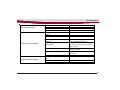
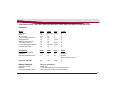
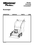
1
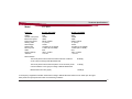
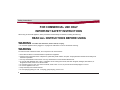
User Manual
X17 ECO Carpet Extractor
This manual is furnished with each new Minuteman X17. This provides the necessary operating and preventive
maintenance instructions. Operators must read and understand this manual before operating or servicing this
machine.
This machine was designed to give you excellent performance and efficiency. For best results and minimal cost,
please follow the general guidelines below:
· Operate the machine with reasonable care.
· Follow the manufacturer’s suggested maintenance instructions as provided in this booklet.
· Use original Minuteman supplied parts.
2
Technical Specifications
Model
X17 ECO
Model No.
Current Max.
Voltage
Vacuum motor power
Brush motor power
Pump motor power
Working width
Gross Weight
Solution tank
Recovery tank
Cable
Suction (sealed)
*Vibration
X17115 / X17115HP
12 Amps
115V
1250W
100W
50PSI / 100PSI
17” (43cm)
110 lbs.
10 Gallon (37.8 LITERS)
7 Gallon (26.5 LITERS)
50 ft.
100 in. of water
< 8.2 ft/s2
X17230 / X17230HP
7 Amps
230V
1250W
100W
50PSI / 100PSI
17” (43cm)
110 lbs.
10 Gallon (37.8 LITERS)
7 Gallon (26.5 LITERS)
50 ft.
100 in. of water
< 2,5 m/s2
Noise emission
The sound pressure level measured under maximum conditions
of use (LwA) according to DIN EN 60335-2-68
83 dB (A)
The sound pressure level measured (at the ear of the driver) under
normal conditions of use (LpA) according to DIN EN 60335-2-68
72 dB (A)
Measurement inaccuracy (KpA)
1,8 dB (A)
*The frequency weighted acceleration measured according to DIN EN ISO 5349 which have an effect upon the upper
limbs (hand-arm-system) amounts under normal working conditions.
3
CE Declaration
4
Table Of Contents
Technical Specifications .......................................................................................................................................................... 3
CE Declaration .......................................................................................................................................................................... 4
Safety Instructions ................................................................................................................................................................... 6
Unpacking Instructions............................................................................................................................................................ 8
Assembly ................................................................................................................................................................................ 10
HANDLE ASSEMBLY ................................................................................................................................................................................ 11
Machine Overview .................................................................................................................................................................. 12
X17 Back & Bottom .................................................................................................................................................................................
Machine Overview ...................................................................................................................................................................................
Handle/ Control Panel ............................................................................................................................................................................
Circuit Breakers ......................................................................................................................................................................................
Momentary Handle ..................................................................................................................................................................................
Brush Switch ...........................................................................................................................................................................................
Vacuum Switch .......................................................................................................................................................................................
Spray Jet / Auxiliary Switch ...................................................................................................................................................................
Solution Tank In-line Filter .....................................................................................................................................................................
Solution Tank Drain Hose ......................................................................................................................................................................
Solution Level Indicator .........................................................................................................................................................................
Brush Removal ........................................................................................................................................................................................
Brush Pressure Gauge ...........................................................................................................................................................................
Removable Recovery Tank .....................................................................................................................................................................
Cord Relief ...............................................................................................................................................................................................
Handle Adjustment .................................................................................................................................................................................
Accessories .............................................................................................................................................................................................
13
14
14
14
15
15
15
15
16
17
17
18
19
20
21
21
22
Maintenance ...........................................................................................................................................................................
Operating Instructions ...........................................................................................................................................................
Troubleshooting .....................................................................................................................................................................
Minuteman International Made Simple Commercial Limited Warranty..............................................................................
23
26
28
30
5
Safety Instructions
FOR COMMERCIAL USE ONLY
IMPORTANT SAFETY INSTRUCTIONS
When using an electrical appliance, basic precautions should always be followed, including the following:
READ ALL INSTRUCTIONS BEFORE USING
WARNING - To reduce the risk of fire, electric shock, or injury:
• Do not leave appliance when plugged in. Unplug from outlet when not in use and before servicing.
WARNING
To reduce the risk of electrical shock, do not expose to rain. Store indoors.
• Never allow children or untrained adults to operate this equipment.
• Keep the area of operation clear of all persons, particularly small children, and pets. Keep bystanders at least 25 feet away from
the area of operation.
• Use only as described in this manual. Use only manufacturer’s recommended attachments.
• Do not use with damaged cord or plug. If appliance is not working as it should, has been dropped, damaged, left outdoors, or
dropped into water, return it to a service center.
• Do not pull or carry by cord, use cord as a handle, close a door on cord, or pull cord around sharp edges or corners.
• Do not run appliance over cord.
• Keep cord away from heated surfaces.
• Do not unplug by pulling on cord. To unplug, grasp the plug, not the cord.
6
Safety Instructions
• Do not handle plug or appliance with wet hands.
• Do not put any object into openings. Do not use with any opening blocked; keep free of dust, lint, hair, and anything that may reduce
air flow.
• Keep hair, loose clothing, fingers, and all parts of body away from openings and moving parts.
• Do not pick up anything that is burning or smoking, such as cigarettes, matches, or hot ashes.
• Turn off all controls before unplugging.
• Use extra care when cleaning on stairs.
• Do not use to pick up flammable or combustible liquids such as gasoline or use in areas where they may be present.
• Connect to a properly grounded outlet only. See grounding instructions.
• If foam/liquid comes out of exhaust openings turn switch off immediately.
• Use only chemicals recommended by dealer/manufacturer.
• This machine must be used only with the power supply cord provided from the manufacturer
– X17115 / X17115HP (748613)
– X17230 / X17230HP (748613CE)
SAVE THESE INSTRUCTIONS
7
Unpacking Instructions
INSPECTION
Carefully unpack and inspect your machine for shipping damage. Each unit is tested and thoroughly inspected before shipment, and any
damage is the responsibility of the delivery carrier who should be notified immediately.
ELECTRICAL
Model Numbers X17115 / X17115HP are designed to operate on a standard 15 amp. 115 volt, 60 hz, AC circuit. Voltages below 105 volts
AC or above 125 volts AC could cause serious damage to the motor.
Model Numbers X17230 / X17230HP are designed to operate on a standard 10 amp. 230 volt, 50 hz, AC circuit. Voltages below 210 volts
AC or above 250 volts AC could cause serious damage to the motor.
WARNING
Electric motors can cause explosions when operated near explosive materials or vapors. Do not operate this machine near flammable
materials such as solvents, thinners, fuels, grain dust, etc.
GROUNDING INSTRUCTIONS
This floor-finishing machine shall be grounded while in use to protect the operator from electric shock. The machine is provided with a
three-conductor cord and a three-contact grounding type attachment plug to fit the proper grounding type receptacle. The green (or green
and yellow) conductor in the cord is the grounding wire. Never connect this wire to other than the grounding pin of the attachment plug.
8
Unpacking Instructions
DANGER
Improper connection of the equipment-grounding conductor can result in a risk of electric shock. Check with a qualified electrician or
service person if you are in doubt as to whether the outlet is properly grounded. Do not modify the plug provided with the appliance — if it
will not fit the outlet, have a proper outlet installed by a qualified electrician.
Model Numbers X17115 / X17115HP are for use on a nominal 115-volt circuit and has a grounding plug that looks like the plug illustrated
in sketch A. Make sure that the appliance is connected to an outlet having the same configuration as the plug. No adapter should be used
with this appliance.
Model Numbers X17230 / X17230HP are for use on a nominal 230-volt circuit and has a grounding plug that looks like the plug illustrated
in sketch B. Make sure that the appliance is connected to an outlet having the same configuration as the plug. No adapter should be used
with this appliance.
(B)
Ground
9
Assembly
Unpack machine.
Use philips screwdriver to
unscrew 4 screws and
remove cover.
Insert handle assembly in
between bushings. Insert
the shoulder bolt through the
bushing and screw into the
handle assembly using
supplied wrench.
Align the teeth on the
bushing and handle assembly before tightening the
adjustment knob.
Spin the adjustment knob
clockwise to tighten.
Attach the wire harness
to the machine.
The wire harness must
be aligned with the patterns
on the connector to fit.
Screw the cover back
with the 4 screws.
10
Assembly
HANDLE ASSEMBLY
The X17 Handle Assembly (D) is not assembled on the
machine when shipped. Follow the instruction on page 10
to connect the handle assembly to the machine.
A
B
C
D
E
F
HANDLE ADJUSTMENT KNOB
SHOULDER BOLT
COVER
HANDLE ASSEMBLY
SCREW
CORD RELIEF
A
D
F
B
E
C
11
Machine Overview
X17 Front
P
A
B
C
D
E
F
G
H
J
HANDLE
RECOVERY DOME LID
RECOVERY TANK
SOLUTION TANK
SOLUTION TANK FILL PORT
FAUCET FILL HOSE
RECOVERY WINDOW
BRUSH MOTOR BELT COVER
VAC SHOE
A
M
B
G
Q
C
Vacuum Connection
K
L
M
N
P
Q
R
VACUUM MOTOR INTAKE COVER
VACUUM CONNECTION TUBE
RECOVERY INLET
D
HANDLE
VACUUM FLOAT SHUT-OFF
RECOVERY WINDOW EXTENSION HOSE
VACUUM MOTOR GASKET
N
E
F
L
K
H
J
12
R
Machine Overview
X17 Back & Bottom
A.
A
D
B
P
B.
C.
D.
E.
F.
G.
H.
J.
K.
L.
M.
N.
P.
(X17115) TWIST LOCK POWER CONNECTOR (SHOWN)
(X17230) POWER CONNECTOR
HANDLE ADJUSTMENT KNOB
AUXILIARY POWER OUTLET (FOR MINUTEMAN MOTORIZED TOOL ONLY)
RECOVERY TANK DUMP HOSE
BRUSH PRESSURE ADJUSTMENT KNOB
OFF AISLE WAND WATER FEMALE QUICK-CONNECT
VACUUM HOSE CONNECTION POINT
IN-LINE SOLUTION FILTER
VAC SHOE
BRUSH
BRUSH END COVER
SPRAY JETS (2)
BRUSH MOTOR
SOLUTION TANK DRAIN HOSE
E
C
F
G
H
13
Machine Overview
Handle/ Control Panel
A
B
C
D
MOMENTARY SPRAY SHUT-OFF
BRUSH SWITCH
VACUUM SWITCH
SPRAY JET \ AUXILIARY SWITCH
Circuit Breakers
The circuit breakers are located on bottom and rear
of the handle assembly.
2
3
14
1
1 BRUSH MOTOR BREAKER - (X17115) 1.5amp
(X17230) 1.0amp
2 VACUUM PUMP BREAKER - (X17115) 12amp
(X17230) 7amp
3 SPRAY JET PUMP\AUX POWER & PUMP BREAKER (X17115) 1.5amp
(X17230) 1.0amp
If any of the functions above are not operating, check if the
circuit breaker buttons have tripped. Press to reset.
Machine Overview
Momentary Handle
(A) When handle is pushed forward the spray jets shut off.
Brush Switch
(B) ON\OFF switch for brush. Flip switch up to (I) position to turn on the brush motor. Flip switch
to (o) position to shut off brush motor.
Vacuum Switch
(C) ON\OFF switch for vacuum. Flip switch up to (I) position to turn on vacuum. Flip switch to (o) position to shut off.
Spray Jet / Auxiliary Switch
(D) Power switch for spray jet and auxiliary function. Push the switch to the (I) position to turn ON the spray jets.
Push switch to (II) position to use the Off-aisle wand. This will power the auxiliary
outlet and will turn the water pump on for the auxiliary connection. See page 22 for connection details.
Make sure to turn off the brush motor when this switch is in the auxiliary mode, or damage to carpet may occur.
15
Machine Overview
Solution Tank In-line Filter
The In-line Filter (B) should be cleaned regularly. To clean:
1. Close the Shut-off Valve (C) by turning the handle 90O clockwise.
2. Next, twist the Filter Cap (A) counterclockwise.
3. Pull the filter out to clean filter and cap.
4. Place filter back into cap, twist cap clockwise onto filter body, tighten by hand.
Note: Using tools to tighten may damage plastic threads.
5. Turn Shut-off Valve (C) counterclockwise to open.
16
Machine Overview
Solution Tank Drain Hose
The solution tank may be drained by removing the
Solution Tank Drain Hose (A) from the Hose Barb (B)
and routing the hose to a floor drain.
Solution Level Indicator
The solution Tank Drain Hose also serves
as a water level indicator for the solution
tank. The amount of water remaining in the
solution tank can be seen through the clear
drain hose.
17
Machine Overview
Brush Removal
• Use a 4mm or 5/32 Hex Tool to remove the flathead screw on the underside of the right side of
the brush housing.
• Pry open the brush housing door.
• Pull brush straight out to the side.
To re-install:
• Insert the end of the brush with drive lugs first, to
match the drive hub on the left side.
• Twist the brush until the drive hub locks in to the
brush.
• Close the brush housing door. The bearing in the
door will insert itself into the end of the brush.
• While holding the housing door closed, reinstall flat-head screw from the underside of
the housing.
18
Machine Overview
Brush Pressure Gauge
The brush pressure gauge informs the operator if the brush
pressure setting is in optimum range. The machine
operates best in the green area. If the machine reaches the
yellow or red range the brush pressure can be lowered by
raising the brush by turning the brush pressure adjustment
knob counter-clockwise.
19
Machine Overview
Removable Recovery Tank
To remove tank:
1. Unclip dump hose from solution tank.
2. Pull recovery tank straight up.
To replace tank:
1. Feed dump hose through opening in solution tank
2. Lower tank into place. Recovery vacuum inlet will rest on vacuum
connection tube (See page 12, items L & M)
3. Clip dump hose to solution tank.
20
Machine Overview
Handle Adjustment
The X17 handle was designed with operator comfort in
mind. The angle position of the handle can be adjusted
to suit the needs of the operator.
Angle Adjustment
The handle can be adjusted without tools by loosening the
Handle Adjustment Knob (A) and rotating the handle
to the desired position.
Cord Relief
Use cord relief to prevent cables from
disconnecting. Lock the cord in place by
looping the cable and threading the cable
through the relief, then pull the cable down
so it locks into place as shown in figure 2.
Figure1
Figure 2
21
Machine Overview
Accessories
• (X17115) C46300-00 - Motorized Tool
• (X17230) C46300-02 - Motorized Tool
Only this tool may plug into the Auxiliary
Power (B).
• The vacuum hose as shown on Page 13 Item (G) must be first
disconnected from the machine back panel. Connect the Suction Hose
(D) tool to the Vacuum Inlet (A).
• Connect the tool Power Cord (E) to the Auxiliary Power (B).
• A Coupler-Quick Connect (G) (p/n: 450295) is required to connect
the tool Solution Hose (F) to the quick-connect Solution Coupling (C).
To turn ON the tool, the auxiliary switch in the machine handle must be
in the (II) position as shown on Page 14 Item (D). The vacuum switch
must also be turned on when using the motorized tool.
• 390070 - Upholstery Tool (Requires Hose Assembly)
• 831255 Scrub/Vacuum Wand (Requires Hose Assembly)
• 828924 or 830750 - Hose assemblies for non-motorized tools.
Do not require QC coupler (G)
• 831019 Pump-Out Hose
• 17603 Vac Out Hose
B
C
A
G
D
F
E
Caution! Brush motor must be turned OFF when using auxiliary function. If the brush motor is ON, damage to
carpet my occur.
22
Maintenance
USER MAINTENANCE INSTRUCTIONS
All service and repairs should be performed by a qualified service representative or electrician. No user serviceable
components are employed in the electrical assembly. No lubrication of the motor is required. BEFORE CLEANING OR
MAINTAINING THE MACHINE, UNPLUG THE ELECTICAL CORD.
Protect equipment from freezing. Severe pumping system damage can occur if allowed to freeze.
DAILY MAINTENANCE
1. Solution tank should be emptied after each use. Flush solution pump system with 1 gallon of clean, hot water.
Operate for 30 seconds through the spray jets, then drain the remaining water with the solution level/drain hose.
(Both require flushing for best performance)
2. Removable recovery tank should be rinsed clean and drained using dump hose. Tank does not need to be removed.
Wipe off any debris from O-ring under dump hose cap.
3. Dome lid should be cleaned. Pull or rinse off any debris from the attached Filter. Place lid upside-down when storing
machine, for ventilation to prevent odor build-up.
4. Vacuum shoe should be cleaned of any debris.
5. Brush should be cleaned of any carpet string or debris.
6. Vac Float Shut-off (page 12, Item P) should be pulled out, inspected, cleaned if necessary.
7. Solution In-Line Filter (page 16) should be inspected and cleaned if necessary.
8. Wheels should be cleaned of hard debris which may damage finished hard-surface floors.
9. Electrical Cord should be inspected for any damage.
10. Vacuum Hose should be inspected for tight fit at the rear of the machine, and to the bottom of the Vac Connection
Tube.
23
Maintenance
BI-MONTHLY/MONTHLY/YEARLY MAINTENANCE
EVERY TWO WEEKS:
1. Purge solution system to remove residue build-up by flushing as follows:
a. Use - 1 quart White Vinegar to two gallons clean hot water - in the solution tank, operate solution pump with
spray jets installed for two full minutes.
b. Drain the remaining solution with the solution level/drain hose (this is important to help keep the hose clear).
c. Use 2 gallons clean hot water in the solution tank, operate solution pump with spray jets installed for two full
minutes. Drain the remaining water with the solution level/drain hose.
d. Important! Repeat 2 gallon rinse as vinegar may affect coloring in carpet.
e. Repeat procedure if machine has not been flushed daily.
2. Remove Brush (page 18), clean any debris off brush hubs at both ends.
3. Wipe off any debris from bottom side of chassis.
4. Rinse off the Dome Lid Filter.
MONTHLY:
1. Check Spray Jets for full width spray pattern. Remove (twist orange cap ¼ turn counter-clockwise) and clean with
soft-bristle brush if necessary. Do not use pins or wire, which can damage the spray tip.
2. Clean the Recovery Window (page 12, item G) by removing (2 screws) and wiping out with a soft cloth, use hot
water and white vinegar or gentle detergent. Take care not to damage the gasket.
o Inspect Gasket for cracks/damage.
24
Maintenance
3. Flush out Recovery Window Extension Hose (page 12, item Q) while Recovery Window is removed by pouring
water/vinegar solution through the hose. Rinse with clear water.
4. Clean off any debris from the Vac Connection Tube & Recovery Inlet (page 12, items L, M).
5. Clean & Inspect Vacuum Motor Gasket (page 12, item R) for damage, and ensure Vac Motor Cover (page 12, item
K) is in place.
6. Inspect Brush Motor Belt for wear (page 12, item H). Replace if necessary.
YEARLY:
1. Have a qualified service technician check the vacuum motor carbon motor brushes once a year or after every 500
operating hours.
CORD STORAGE
The X17 is supplied with a detachable cord for ease of storage.
•
•
•
•
•
•
Regularly inspect cord for signs of damage. If cord is damaged replace immediately.
Do not use with damaged cord or plug. If appliance is not working as it should, has been dropped, damaged, left
outdoors, or dropped into water, return to service center.
Do not pull or carry by cord, use cord as handle, close a door on cord, or pull cord around sharp edges or corners. Do
not run appliance over cord. Keep cord away from heated surfaces.
Do not unplug by pulling cord. To unplug, grasp the plug, not the cord.
Do not handle plug or appliance with wet hands.
This equipment should be stored indoors and not exposed to rain.
25
Operating Instructions
OPERATING INSTRUCTIONS
Maximum Water Temperature
FILLING THE X17
Remove clear solution cover lid from front of machine, or use the supplied faucet fill hose, by
pulling hose out and holding rubber inlet against faucet. Fill solution tank with desired amount of
warm water and add liquid cleaning chemical, Minuteman Extraction Shampoo order #902163.
(See instructions on container for proper dilutions.) DO NOT USE powdered cleaning chemicals.
Powders are unlikely to dissolve thoroughly, resulting in clogging the inline solution strainer and
other fittings. This can reduce or stop solution flow to the pump and spray jets.
Carpet should be thoroughly vacuumed and obstacles relocated before beginning the cleaning
cycle. Heavy traffic lane areas should be pre-treated or spotted with Minuteman Pre-Treat order
#902183 for best results.
TO BEGIN CLEANING:
1. Always work away from the cord.
2. Machine operates by pulling backwards over carpet.
3. The recovery dome lid, page 12, item B, should be properly seated on Recovery Tank, item C, for proper vacuum recovery.
4. See page 14, Control Panel Switch Identifications:
Normal Cleaning Mode
1. Turn on vacuum switch (C).
2. Turn on brush switch (B).
3. Turn on the solution pump (D) to position 1.
4. Adjust brush pressure at rear of machine, until brush pressure gauge reads in green zone.
5. Solution pump should be turned off by either using the momentary bail, item A,or flip the switch spray jet to the center
position, item D, 6" before the end of each cleaning pass.
26
Operating Instructions
CONTINUED...
During the cleaning cycle, care should be taken not to allow foam to build up in the recovery tank. If this should happen, the
machine should be turned off. Defoamer order #910543 should be added to the recovery tank only, never into the solution
tank. Foam should not be seen inside the right side of the dome lid.
The recovery water level can be viewed from the operator’s position of the machine through the left side of the visible
recovery dome. The X17 has a float ball shut off located in the recovery tank that cuts off suction to the vacuum hose. When
the recovery tank is full, the vacuum motor will become noticably louder and the machine will not pick up water. Recovery
tank must be emptied. (NOTE : Never tilt machine completely back with recovery tank in place. Always remove tank and set
to the side before tilting complete machine.) To empty the recovery tank use the recovery tank dump hose, page 13, item D.
Unclip the hose from the tank and turn the cap a quarter turn counter-clockwise and dump waste water into a floor drain or
slop sink.
27
Troubleshooting
Troubleshooting Guide
Caution! Unplug power cord before servicing machine components.
Problem
Machine does not function
No water dispensed from spray jets
Possible Cause
Power cord may be disconnected at the
twist lock or wall outlet.
Wall outlet breaker may have tripped
Circuit breaker in handle tripped.
Solution tank in-line filter valve may be
closed.
Sprayjet Switch is in OFF (O) or AUX (II)
position
No water in solution tank.
Solution hoses may be clogged or kinked.
Remedy
Check connections and reconnect if
necessary.
Reset breaker.
Reset breaker.
Open valve.
The spray jets may be clogged.
Remove the spray tips and clean as
required. Do not clean out the hole in the
jet with a pin or wire. This may cause
permanent damage.
Flip sprayjet switch to ON (I) position.
Fill solution tank.
Check hose for clogs, remove any debris if
found. Replace kinked hose if found.
Solution tank in-line filter may be clogged. Clean strainer thoroughly.
Spray intermittent or streaked
28
Troubleshooting
Brush does not turn ON
Solution recovery is reduced
Circuit breaker in handle tripped.
Belt is damaged
Debris is lodged in the brush housing
Switch is in OFF (O) position
Dome lid filter or vac float shut off may be
clogged
Recovery dome lid is not seated properly.
Reset breaker.
Replace belt
Remove debris
Flip switch to ON (I) position.
Rinse out items
Recovery tank is not seated properly over
intake tube.
Recovery tank dump hose may not be
closed properly.
Reposition recovery tank so the intake
tube is inserted into the inlet.
Disconnect cap from drain hose then
reconnect, to ensure the cap and hose
snap together.
Check the gasket on the lid for damage.
Replace if needed.
Check vac shoe for debris and remove if
necessary.
Replace vac shoe.
Reset breaker.
Bad seals on recovery dome lid.
Vac shoe may be clogged.
Vacuum motor does not start.
Vac shoe may be worn.
Circuit breaker in handle may have
tripped.
Motor carbon brush may be worn.
Switch is in the OFF (O) Position
Reposition dome lid
Contact a qualified service technician.
Flip the switch to the ON (I) Position
29
Minuteman International Made Simple Commercial Limited Warranty
REVISION F EFFECTIVE 6/1/2009
Minuteman International, Inc. warrants to the original purchaser/user that the product is free from defects in workmanship and materials
under normal use. Minuteman will, at its option, repair or replace without charge, parts that fail under normal use and service when operated
and maintained in accordance with the applicable operation and instruction manuals. All warranty claims must be submitted through and
approved by factory authorized repair stations.
This warranty does not apply to normal wear, or to items whose life is dependent on their use and care, such as belts, cords, switches, hoses,
rubber parts, electrical motor components or adjustments. Parts manufactured by Minuteman are covered by and subject to the warranties
and/or guarantees of their manufacturers. Please contact Minuteman for procedures in warranty claims against these manufacturers.
Special warning to purchaser — Use of replacement filters and/or prefilters not manufactured by Minuteman or its designated licensees, will
void all warranties expressed or implied. A potential health hazard exists without original equipment replacement.
All warranted items become the sole property of Minuteman or its original manufacturer, whichever the case may be.
Minuteman disclaims any implied warranty, including the warranty of merchantability and the warranty of fitness for a particular purpose.
Minuteman assumes no responsibility for any special, incidental or consequential damages.
This limited warranty is applicable only in the U.S.A. and Canada, and is extended only to the original user/purchaser of this product.
Customers outside the U.S.A. and Canada should contact their local distributor for export warranty policies. Minuteman is not responsible for
costs or repairs performed by persons other than those specifically authorized by Minuteman. This warranty does not apply to damage from
transportation, alterations by unauthorized persons, misuse or abuse of the equipment, use of non-compatible chemicals, or damage to
property, or loss of income due to malfunctions of the product.
If a difficulty develops with this machine, you should contact the dealer from whom it was purchased.
This warranty gives you specific legal rights, and you may have other rights which vary from state to state. Some states do not allow the
exclusion or limitation of special, incidental or consequential damages, or limitations on how long an implied warranty lasts, so the above
exclusions and limitations may not apply to you.
30
Cord Electric Group: Three years parts, two years labor, ninety days travel (Not to exceed two hours)
Exceptions……….
Model
Parts
Labor
Poly
Travel
Port A Scrub
MPV 13
MPV 14 & 18
V Series Upright Vacuums
Rapid Air Blower
Explosion Proof Vacuum
X12, X12H & TRS 14
E17 & E20 Electric Scrubbers
1 yr
1 yr
2 yrs
1 yr
1 yr
1 yr
1 yr
1 yr
6 months
0
1 yr
1yr
1 yr
1 yr
1 yr
6 months
10 yrs
0
0
0
10 yrs
0
10 yrs
10 yrs
0
0
0
0
0
0
0
0
Pneumatic Vacuums
3 yr
1 yr
0
0
Description
Parts
Labor
Poly
Travel
Battery Operated Group
Sweepers
Internal Combustion Group
3 yrs
1 yr
1 yr
2 yrs
1 yr
1 yr
10
10
10
90 days
90 days
90 days
Not to exceed two hours
Exception: PAS 14B
Battery Chargers:
Replacement Parts:
Batteries:
Polyethylene Plastic Tanks:
1 yr
1 yr
10 yr
0
One year replacement
Ninety days
0-3 months replacement, 4-12 months pro-rate
Tanks have 10yr warranty, no additional labor
31
Excellence Meets Clean
Minuteman International · 14N845 U.S. Route 20 · Pingree Grove, Illinois 60140 USA
Phone 800-323-9420
www.minutemanintl.com
A Member of the Hako Group
988725UM
Rev E 10/11