1
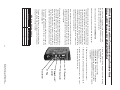
Communicating
Controls Service
Manual
History 1977–1991
Theor y of Operation | Common Components
Sequence of Operation | Ser vice/Troubleshooting
Table of Contents
Warnings and Cautions ....................................................... 2
Theory of Operation
Communicating Controls ......................................................... 3
Dehumidification Cycle ............................................................ 4
Communications....................................................................... 5
Equipment Setup ...................................................................... 5
Alert Signaling .......................................................................... 5
Approved Combinations .......................................................... 6
Alert Code Addendum .............................................................. 7
Low Voltage Wiring Diagram
Communicating Indoor and Communicating
Outdoor Type ......................................................................... 9
24 Volt Thermostat with a Communicating Air Handler
and a Communicating Outdoor Unit converted to a
24 Volt Control using Harness Kit BAYACHP024A .............10
Communicating Indoor and a Single Stage
A/C Outdoor Unit ................................................................ 12
Common Components
User Interface Assembly ........................................................ 13
Personality Module................................................................. 13
Variable Speed Indoor Blower Motor
Serial Port Communication .....................................................14
Three Stage Gas Furnaces
Features ................................................................................... 15
Heating Cycle Checks and Limits........................................... 16
Inducer Motor Drive Board .................................................... 17
Silicon Nitride Ignitor Learning Routine ............................... 18
IFC LEDs....................................................................................19
IFC Inducer Motor Learning Routine Sequences ..................19
Fault Detection ........................................................................19
Contingency Operating Mode ............................................... 21
User Interface Display Navigation Tree ................................. 22
Gas Valve Adjustment Procedure .......................................... 24
Unit Test Cycle ......................................................................... 25
Venting Table ........................................................................... 27
Sequence of Operation .......................................................... 28
Pressure Switch Testing .......................................................... 30
Pressure Switches Interconnecting Hoses ............................ 31
Pressure Switch Operating Pressure Chart........................... 33
Furnace Trouble Shooting Checklist ...................................... 34
Furnace Alert Code Addendum ............................................. 36
Communicating Air Handler
Components ............................................................................ 37
Communicating Mode Drawing ............................................ 39
User Interface Display Assembly........................................... 41
Air Handler Sequence of Operation &
LEDs Identification .............................................................. 42
Unit Test Mode ........................................................................ 45
Fault LED and Error Code Addendum ................................... 46
Air Handler Trouble Shooting Checklist ................................ 47
Communicating Two Compressor Outdoor Units
Features ................................................................................... 48
Charge Assist™ Control ......................................................... 49
Internal Refrigerant Piping ..................................................... 49
Field Refrigerant Piping.......................................................... 50
Duct Work ................................................................................ 50
Low Ambient Cooling ............................................................. 50
Manual Charging Instructions ............................................... 51
R-22 A/C Charging Charts....................................................... 52
A/C Schematic Diagrams........................................................ 52
R-22 H/P Charging Charts ....................................................... 54
H/P Schematic Diagrams ....................................................... 54
Charge Assist™ Sequence of Operation............................... 56
Charge Assist™ LED Indications ........................................... 56
Charge Assist™ Procedure Details ........................................ 57
Charge Assist™ Tool BAYCAKT001AA................................... 59
Charge Assist™ Procedure for a Non-Communicating
24 VAC Control System ....................................................... 60
Charge Assist™ LEDs Summary Chart ................................. 61
Charge Assist™ LED Flash and ERR Code Checklist ............ 62
Trouble Shooting
GO/ NO GO Test for Serial V.S. Blower Motors ..................... 63
Quick Field Test of a Serial Port V.S. Blower Motor .............. 65
Charge Assist™ Control Trouble Shooting ........................... 67
Charge Assist™ Control Fault LED Flash Code and
Trouble Shooting Sequence............................................... 69
Outdoor Unit’s Alert Code Addendum .................................. 73
Coil and Ambient Temperature Sensors
Temperature/Resistance Table .............................................74
Liquid Line Temperature Sensor
Temperature/Resistance Table ............................................ 75
Liquid Line Pressure Transducer
DC Volts/PSIG Pressure Table ..............................................76
External Accessory Temperature Senor
Temperature/Resistance Table ............................................ 77
Error Code 91 .......................................................................... 78
Error Code 89, 91, and 126
(System Communicating Trouble Shooting) ..................... 88
Communicating System Voltage Readings........................... 95
All information contained herein
is subject to change without notice.
Note: This publication is general in nature and is intended for INSTRUCTIONAL
PURPOSES ONLY. It is not to be used for equipment selection, application,
installation, or specific service procedures.
1
Warnings and Cautions
WARNING
CAUTION
CAUTION
All information contained herein
is subject to change without notice.
DO NOT TOUCH IGNITER. IT IS EXTREMELY HOT.
!
BURN HAZARD
LABEL ALL WIRES PRIOR TO DISCONNECTION
WHEN SERVICING CONTROLS. WIRING ERRORS CAN
CAUSE IMPROPER AND DANGEROUS OPERATION.
VERIFY PROPER OPERATION AFTER SERVICING.
LABELING WIRES!
CAUTION
SYSTEM CONTAINS OIL AND REFRIGERANT UNDER
HIGH PRESSURE. RECOVER REFRIGERANT TO RELIEVE
PRESSURE BEFORE OPENING SYSTEM.
Failure to follow proper procedures can result in personal
illness or injury or severe equipment damage.
! CAUTION
CONTAINS REFRIGERANT!
Do NOT install return air through the side of the furnace cabinet on horizontal applications.
NOTE:
Minimum return air temperature is 55°F.
Do NOT install return air through the back of the furnace cabinet.
Where there is no complete return duct system,
the return connection must be run full size from
the furnace to a location outside the utility room,
basement, attic, or crawl space.
Be careful of sharp edges on equipment or any
cuts made on sheet metal while installing or
servicing. Personal injury may result.
Sharp Edge Hazard
Safety Hazard
!
SHOULD OVERHEATING OCCUR, OR THE GAS
SUPPLY FAIL TO SHUT OFF, SHUT OFF THE GAS
VALVE TO THE UNIT BEFORE SHUTTING OFF THE
ELECTRICAL SUPPLY.
FAILURE TO FOLLOW THIS WARNING COULD RESULT
IN PROPERTY DAMAGE, PERSONAL INJURY, OR
DEATH.
! WARNING
FIRE OR EXPLOSION HAZARD
Throughout this manual there are procedures where voltage may be present and gas or refrigerant system
checks may be required. Read all cautions and warnings on this page before proceeding.
!
WARNING
SAFETY HAZARD
THIS INFORMATION IS INTENDED FOR USE BY
INDIVIDUALS POSSESSING ADEQUATE BACKGROUNDS OF ELECTRICAL AND MECHANICAL EXPERIENCE. ANY ATTEMPT TO REPAIR A CENTRAL AIR
CONDITIONING PRODUCT MAY RESULT IN PERSONAL INJURY AND OR PROPERTY DAMAGE. THE
MANUFACTURER OR SELLER CANNOT BE RESPONSIBLE FOR THE INTERPRETATION OF THIS INFORMATION, NOR CAN IT ASSUME ANY LIABILITY IN CONNECTION WITH ITS USE.
!
FIRE OR EXPLOSION HAZARD
FAILURE TO FOLLOW THE SAFETY WARNINGS EXACTLY COULD RESULT IN SERIOUS PERSONAL INJURY, PROPERTY DAMAGE, OR DEATH. IMPROPER
SERVICING COULD RESULT IN DANGEROUS OPERATION, SERIOUS PERSONAL INJURY , PROPERTY DAMAGE, OR DEATH.
! WARNING
SERVICE PROCEDURES HAZARD
WARNING
BODILY INJURY CAN RESULT FROM HIGH VOLTAGE
ELECTRICAL COMPONENTS, FAST MOVING FANS,
AND COMBUSTIBLE GAS. FOR PROTECTION FROM
THESE INHERENT HAZARDS DURING INSTALLATION
AND SERVICING, THE ELECTRICAL SUPPLY MUST BE
DISCONNECTED AND THE MAIN GAS VALVE MUST
BE TURNED OFF. IF OPERATING CHECKS MUST BE
PERFORMED WITH THE UNIT OPERATING, IT IS THE
TECHNICIAN’S RESPONSIBILITY TO RECOGNIZE
THESE HAZARDS AND PROCEED SAFELY.
!
Voltage Hazard
Disconnect power to the unit before removing the
blower door. Allow a minimum of 10 seconds for IFC
power supply to discharge to 0 volts.
Failure to follow this warning could result in property
damage, personal injury or death.
! WARNING
CARBON MONOXIDE POISONING HAZARD
FAILURE TO FOLLOW THE SERVICE AND/ OR
PERIODIC MAINTENANCE INSTRUCTIONS FOR THE
FURNACE AND VENTING SYSTEM, COULD RESULT
IN CARBON MONOXIDE POISONING OR DEATH.
2
s
s
s
s
All information contained herein
is subject to change without notice.
%ACH COMPONENT IN THE SYSTEM HAS A PREASSIGNED
electronic address.
63 )NDOOR "LOWER 3PEEDS ARE AUTOMATICALLY SET
when the Outdoor Unit is a communication type. The
Cooling CFM per ton, and the Heating CFM can be
changed at the Air Handler or Gas Furnace User Inter
Face display.
7HEN THE SYSTEM IS OPERATING ALL OPERATIONAL
messages and alerts will be sent on the data line
to all communicating components in the system.
All compatible components can read and send
messages on the data line.
4HE!IR (ANDLER OR THE 'AS &URNACE CONTROL WILL BE
the Bit Master in a communicating Comfort Control
system. The Bit Master can be considered to be the
system clock. It places timing pulses on the data line
to indicate to the other connected devices exactly
when their data bits can be transmitted on the data
line bus.
Communication Controls Theory Of Operation
The indoor thermostat, indoor unit, outdoor unit and
other accessories communicate using two of the three
thermostat wires required in this type of installation.
The three wires are the; Data line (D), Common Line (B)
and 24VAC Power Line. The indoor unit’s transformer
provides 24 Volt AC Power to itself and the thermostat.
The outdoor unit has its own 24VAC transformer and
will only require the Data Line and the Common Line
for operation.
s 4HREE WIRES NEEDED BETWEEN THE INDOOR UNIT AND
thermostat (D, R, & B)
s 4WOWIRESNEEDEDBETWEENTHEINDOORANDOUTDOOR
unit (D & B).
s 4HE COMMUNICATING SYSTEM IS A MICROPROCESSOR
based system which operates as an open
communications system. This type of control system
can be expanded easily. When an additional item is
added to the control system and powered up, such as
a communicating IFD air cleaner, a Telephone Access
Module “TAM” or a communicating humidifier, it
will establish communications automatically with
the other components in the system.
3
All information contained herein
is subject to change without notice.
s -INIMUMCOMPRESSORRUNTIMEISTHREEMINUTES
s -INIMUMCOMPRESSOROFFTIMEISlVEMINUTES
s &ROST#ONTROLCYCLEISUSEDWHENAHUMIDIlERISINstalled and the control system has an outdoor temperature sensor installed. The frost control works by
reducing the humidity level in the home when outdoor conditions can cause condensation or frost to
form on windows. The factory setting is five. To reduce the condensation or frost on the windows, lower the number. If the humidity is too low in the home
at the factory setting of five, increase the number.
See advanced thermostat setup for programming
setup instructions.
When the indoor humidity in the cooling cycle is above
the thermostat humidity set point, the thermostat message being sent can cause the system to continue to
run to a maximum of three degrees below the thermostat set point. This will help control humidity under
light loads conditions. This cycle is adjustable from 1
to 3 degrees in the Installer Setup Menu #0380 and
#0383. Refer to Comfort Control Installer’s Guide setup
menu for complete menu.
Indoor Dehumidification Control Cycle
Communication Controls Theory Of Operation:
900 Series Comfort Control
The communicating system’s comfort control is a true
thermostat sensing indoor dry bulb temperature and
relative humidity. When the thermostat senses the indoor air temperature or humidity has changed from
the set point it will send an operational message on
the data line. All units that are connected to the data
line will read this operational message. The unit or
units being called for will start and run on first stage; a
gas furnace will start in the second stage of operation
and then go back to the first stage of operation. The
thermostat also sends blower speed information.
Operation is similar to a standard two-stage thermostat. When the indoor temperature does not move
back towards the thermostat set point in a given time
period or the temperature continues to move away
from the set point the thermostat will change its operational message on the data line. The new message
will be a call for the next stage of operation. When the
indoor temperature moves back towards the set point
the thermostat will again change its operational message on the data line and the units running will then go
back to first stage of operation. When the indoor temperature is back to the set point temperature and the
minimum run time for the equipment has been met,
the thermostat will send another new operational message that the system is to shut down and any indoor
blower off-delays will begin.
4
Reliable Communications
To insure that the message being sent by a component
(ex. thermostat, indoor or outdoor unit) is not being
over written by another components operational
message, noise, or electrical interference, the sending
component will monitor its own operational message
on the data line. The message must match the original
message. If the message does not match the sending
components original message, it will stop sending its
message and try again later. When a good operating
message has been received by the indoor and the
outdoor unit the system will begin to operate. The
Indoor and Outdoor units use this operating message
Equipment Setup
When the system is powered up, the microprocessors
in the thermostat, indoor unit, outdoor unit and other
accessories will establish communications with each
other. This is known as a plug and play system. A
minimum amount of set up may be required at
the indoor thermostat for approved equipment
combinations and their accessories, reference page 6,
Approved Combinations.
until a different operational message is received. This
operating message is being sent repeatedly. If the
system is running and the units do not receive a good
operating message within four minutes the system
will shut down. This four minute run time prevents the
system from shutting down if a component receives
a corrupted operating message. A corrupted message
could be caused by two components sending a
message at the same time, over written message,
noise, or electrical interference noise on the data line.
When commutations are reestablished the system will
again operate.
The information supplied by the outdoor unit is used
by the indoor unit to set up the indoor blower airflow,
CFM, and any delays needed. The thermostat uses
the information from the indoor and outdoor units
to configure the thermostat for the number stages of
compressor operation, Air Conditioner or Heat Pump,
type of heat - fossil fuel or electricity and number of
stages of heat installed. No dip switches to set.
All information contained herein
is subject to change without notice.
Communication between Furnace IFC and V.S.
Motor or Inducer Motor Drive Board
The Alert screen will show the diagnostic Err code
number. When multiple fault codes exist at the same
time it will cycle through (up to 5 max) by showing the
next code each time it comes to the diagnostic screen.
The thermostat will not switch back and forth when on
any other screen. The service LED will not be used for
signaling emergency heat or anything else when the
thermostat has received an Alert message.
Fault Detection & Alert Signaling
The thermostat, indoor and outdoor units can provide
notification of system faults. When a fault is detected
by the indoor unit, outdoor unit, or thermostat a coded
message is sent on the Data Line to the thermostat
and will be displayed as an Alert. The thermostat will
turn on the red Service LED and the display will switch
back and forth between the main screen and an Alert
screen.
5
Clearing Alerts and Approved Combinations
Clearing Alerts
When a fault or faults are corrected and the faults are
cleared at that unit’s microprocessor, that microprocessor will quit sending the coded fault message. The
thermostat will then turn off the red Service LED and
quit switching the display back and forth between the
normal display and the Alert screen display.
Approved Combinations
4H/3C HP, w/ 1 Aux, 1 EH, gas or electric
4H/2C HP, w/ 2 Aux, 2 EH, gas or electric
4H/1C HP, w/ 3 Aux, 3 EH, gas or electric
3H/3C HP, w/ 0 Aux, 0 EH
3H/2C HP, w/ 1 Aux, 1 EH, gas or electric
3H/1C HP, w/ 2 Aux, 2 EH, gas or electric
2H/2C HP, w/ 0 Aux, 0 EH
2H/1C HP, w/ 1 Aux, 1 EH, gas or electric
1H/1C HP, w/ 0 Aux, 0 EH
3H/3C conventional, gas or electric
2H/3C conventional, gas or electric
1H/3C conventional, gas or electric
0H/3C conventional
3H/2C conventional, gas or electric
2H/2C conventional, gas or electric
1H/2C conventional, gas or electric
0H/2C conventional
The following sequence of operation will occur when
there are more stages of heat installed than the approved combinations list above shows. Example:
When a two stage heat pump is installed with a three
stages gas furnace the thermostat can only call for two
stages of auxiliary heat, as shown above. When the
thermostat calls for first stage auxiliary heat the furnace IFC will operate the furnace in the second stage of
heat. When the thermostat calls for second stage auxiliary heat, the furnace IFC will operate the furnace in
the third stage of heat.
6
All information contained herein
is subject to change without notice.
Alert Code Addendum
7
9 Flash
All information contained herein
is subject to change without notice.
Equipment Change Alert
Alert Code Addendum
126
ERR 126
None
Equipment does not match
valve stored at startup2
All information contained herein
is subject to change without notice.
1 Comfort Control will switch to “OFF” until this fault condition clears.
2 A device has changed since auto discovery (see Installer Guide ISU 0706 to reset)
3 Pub. No. 18-HD32D2-2, Revision 3, 08/07/2007
8
All information contained herein
is subject to change without notice.
Communication Controls Theory Of Operation:
With Communicating Outdoor Unit
9
0 and X2 Thermostat wires are used
on heat pumps installations only.
24 Volt Common B may not be
required at the thermostat.
All information contained herein
is subject to change without notice.
24 Volt Thermostat with a Communicating Outdoor Unit
Using a 24V Harness Kit #BAYACHP024A
ODT2 not required on a two stage
auxiliary electric heater.
Notes:
10
18 AWG
Wire Size
225 FT.
150 FT.
Max Wire Length
All information contained herein
is subject to change without notice.
Transformer
J1 Plug
Control
ChargeAssist™
LO Contactor
HI Contactor
8. Please retain communication harness and transformer for possible future use.
7. Reconnect power, which was disconnected in step #1.
6. Replace the control compartment cover panel.
5. Place the proper wiring diagram over the existing
unit wiring diagram.
If the unit is a:
s "45HEATPUMPUSE$
s OR"45HEATPUMPUSE$
s "45COOLINGONLYMODELUSE$
s OR"45COOLINGONLYMODELS
use D154657
24 Volt Thermostat with a Communicating Outdoor Unit
Using a 24V Harness Kit #BAYACHP024A
For instructions, components and diagrams used in
this kit, order kit #BAYACHP024A. Shown here is an
excerpt from the kit for reference:
1. Be certain power to unit is DISCONNECTED.
2. Remove cover panel on control box compartment.
3. Disconnect and remove the existing communicating
control harness assembly. This harness consists of
the 4 wire plug assembly (J1). Disconnect/remove:
the red wire and fuse assembly from the transformer;
the blue lead from the transformer; the green/yellow
transformer ground wire; the brown wire going out
to field connections; the blue wire going out to field
connections and the double blue wire connection
terminal at the lo contractor coil.
Also disconnect and remove the two transformer
primary wires; brown/red wire coming from the start
capacitor and the black/blue wire coming from the
hi contractor. The transformer is no longer used and
should be removed.
4. Connect the 24 volt harness (supplied with the kit) to
the control board, where the communicating harness
was removed (connector J1). Take the double blue
lead terminal and connect to the lo contractor coil,
where the previous blue lead was removed. Route
the remaining yellow, blue, orange, red, black, and
yellow/red wires out for field connection, as shown.
If the unit is a cooling only model (not a heat pump),
the orange and black leads will not be used and
should be capped off.
The table below defines maximum total length of low
voltage wiring from the outdoor unit to the indoor
unit, and to the Comfort Control.
16 AWG
300 FT.
NEC Class II Wiring, 24 Volts
14 AWG
11
All information contained herein
is subject to change without notice.
Comfort Control with a Single Stage 24 Volt Controlled A.C.
12
All information contained herein
is subject to change without notice.
The on-board 24VAC automotive type fuse is in series
with the 24VAC terminal (R). If the fuse opens, the control’s microprocessor remains powered. If the system is
running it will shut down all operation. A gas furnace’s
gas valve or an air handler’s auxiliary heat will turn off
at once and there will be a several second delay before
the gas furnace’s Inducer motor and indoor blower is
shut down. The User Interface Assembly will display
CHECK FUSE when the last four faults are displayed.
24VAC Fuse
If the PM is not plugged back onto the control board, an
ERROR message will be displayed at the thermostat.
Note: Do not remove the Personality Module (PM)
from its control board; it is model number and serial
number specific to this unit.
If the PM is unplugged from its control board after the
system is powered up, the system will continue to operate.
The stored information is downloaded into the unit’s
controller when the unit is powered up. This information is sent to other microprocessor controls connected to the Data Line.
s
s
s
s
s
s
s 4YPEOFINDOORUNITAIRHANDLERORGASFURNACE
s 6ARIABLE SPEED OR FOUR SPEED INDOOR BLOWER AND
horsepower of blower
4HENUMBEROFSTAGESOFHEAT
4YPEOFTHEOUTDOORUNIT!#OR(0
.UMBEROFCOMPRESSORSTAGESOR
3IZEOFTHEOUTDOORUNIT
)NDOOR!IR&LOWAND$ELAYS
!LERTS
The communicating microprocessor controls in the
indoor and outdoor units have a Personality Module
plugged onto their control. The Personality Module
(PM) contains the following system specific information:
Personality Module
Gas Furnace and Air Handler Common Components
User Interface Assembly
The indoor User Interface Assembly will display the
model and serial number during normal unit operation. In addition, the following information can also be
accessed through the display.
s 4HE5NITS-ODEL3ERIAL.UMBER.ORMAL$ISPLAY
s 3YSTEM3TATUS-ODEOF/PERATION(EATING3TAGE
2 or 3, Cooling Stage 1, 2 or 3, or OFF, thermostat not
calling)
s 2EQUESTED !IRmOW #&- WHEN THE THERMOSTAT IS
calling.
s )NDOOR5NITS!LERT#ODES
s 5NIT4EST#YCLE(EATING#YCLE/NLY
s "LOWER-OTOR3PEED20-WHENOPERATING
s &OSSIL&UEL$RAFT)NDUCER3PEED20-WHENOPERATing)
s ,AST&OUR!LERTS
s 2EPLACEMENT0ART,IST
s 0ERSONALITY-ODULE3ERIAL.UMBER
s 3TAND ALONE OPERATION WITHOUT A THERMOSTAT $UTY
Cycling of gas equipment (Contingency Mode)
s %XIT
13
All information contained herein
is subject to change without notice.
Single phase 120 or 240 volts AC power is applied to
the motor module and IS NOT turned on or off by the
IFC or AHC. The V.S. Motor module converts the AC
power to DC power. Some of the DC voltage is reduced
to power the microprocessor inside the V.S. Motor
module. A communication fault will appear if line voltage is removed from the V.S. Motor module and the
IFC or AHC system is then repowered. When blower
operation is called for, the V.S. Motor module turns the
DC power on and off to each leg of its three phase motor in a rotating manner. The V.S. Motor Module will
increase the voltage and number of Hertz it applies
to its three phase motor to increase its speed, or decrease the voltage and Hertz to slow it down. The V.S.
Motor module monitors the motor’s RPM and power
and compares this information to its programmed information. If the RPM and power do not align with the
programmed information, the V.S. Motor module will
change its output voltage and Hertz to bring the airflow
back in line with its program.
Variable Speed Indoor Blower Motor Operation
Serial Port Communication
The Serial Port Communication type of variable speed
motor operates the same as the 24 volt controlled V.S.
type except the on/off control and speed signals are
now a digital command signal. The Motor module receives the command signal and replies back to the indoor product control board. This type of motor module
is not preprogrammed at the factory. The horsepower,
operating speeds, maximum RPM and direction of rotation information are stored in the Personality Module, which is located on the Gas Furnace Control (IFC)
or an Air Handler Control (AHC). When the system is
powered up, the V.S. Motor programming information stored in the Personality Module is sent to the V.
S. Motor module. The Serial Port Communication V.S.
Motor has four low voltage wires plugged into it. The
four wires are; (1) The TX wire which is used to send
all digital information, (2) The RX wire which is used
to receive all digital information, (3) 24 Volt AC and DC
common wire, and (4) 12 Volt DC wire. The 12 volts are
supplied by the IFC or AHC control and used to power
the input and output circuits, optic-couplers, in the V.S.
Motor.
14
Three-Stage Gas Furnace
Features
s
s
s
s
s
s
s
s
s
4HREE3TAGESOFHEATPROVIDEBETTERCOMFORTCONTROL
o 1st Stage – 40% – Typical Input
o 2nd Stage – 65% – Typical Input
o 3rd Stage – 100% – Typical Input
#OMMUNICATING #ONTROL 3YSTEM EQUALS SIMPLE
installation, limited diagnoses at the thermostat,
greater diagnoses capabilities at the Furnace’s User
Interface Module.
3YSTEMOPERATIONANDSETPOINTCHANGESCANBEDONE
via telephone with a Telephone Access Module, when
installed.
6ARIABLE SPEED OPERATION OF THE 0HASE )NDUCER
Motor will allow furnace operation with up to 200
equivalent feet of vent pipe and pipe fittings.
6ARIABLE 3PEED )NDOOR "LOWER WILL PROVIDE MORE
efficient operation while maintaining rated airflow
over a greater range of conditions.
(ASA(EATING4EST#YCLEWHICHWILLCYCLETHEFURNACE
through it three stages of heat rapidly.
#APABLE OF STAND ALONE OPERATION #ONTINGENCY
Mode) duty cycling of heat.
#ONVERTIBLE TO 0ROPANE 'AS CHANGE ORIlCES ONLY
Operates on Propane at 3.5” manifold pressure.
4OENSURETHEFURNACESHEATINGEFlCIENCYTHEFURNACE
IFC will go through a RESET to the Inducer’s Motor’s
learning routine after :
o 150 Cycles in First Stage Heat
o 100 Cycles in Second Stage Heat
o 50 Cycles in Third Stage Heat
15
o Or whenever power is interrupted to the furnace
and is then restored
s 4HE FURNACE )&# COMMUNICATES THE FOLLOWING
information with the Indoor V.S. Blower Motor:
o Rotation Direction
o Speed & Max CFM
o Start & Stop Commands
s !LSO#HECKSTHE63-OTORHORSEPOWER(0ANDWILL
send an error message if HP is not correct.
s 4HEFURNACE)&#CONTROLSTHE(EATING#YCLES#&-ALL
other airflows are controlled by the comfort control
thermostat.
s 3ILICON.ITRIDE(OT3URFACE)GNITER
o IFC uses the proven Adaptive Learning Routine
providing reliable ignition and prolonging the life
of the Hot Surface Igniter
s #OMFORT2© INDOOR BLOWER 2AMP CYCLE AND COOLING
airflows are set at the comfort control thermostat.
No Dip Switches to set.
s (EATING63 )NDOOR "LOWER -OTOR TIME DELAY TO OFF
selectable at the User Interface Module.
s 4HESE FURNACES CAN ONLY BE CONTROLLED BY A
communicating comfort control.
s 4HE THERMOSTAT AND FURNACE COMMUNICATE DIGITALLY
with each other. The Data and Common thermostat
wires are used for communications.
s 4HEFURNACEPROVIDES6OLTS!#POWERTOOPERATE
the thermostat.
All information contained herein
is subject to change without notice.
Three-Stage Gas Furnace
IFC Control / Part # Cnt 04836
Heating Cycle
The Furnace Integrated Furnace Control, IFC, receives
a message from the comfort control thermostat to operate in the first, second or third stage of heat.
Primary Limit
Manual Reset Flame
Roll-Out Limit
16
Comfort Control Thermostat
Checks Performed Before Starting a Heating
Cycle
The furnace’s IFC will check to see if all of the limits
are closed and the pressure switches for stage
one (PS-1) and stage two (PS-2) are open. These
operating components are always checked before a
heating cycle can begin. Stage three (PS-3) pressure
switch is not checked until a call for third stage heat
is received by the furnace’s IFC. The furnace’s IFC will
always start the heating cycle in the Second Stage of
heat and then goes to First Stage heat, or whatever
stage the comfort control thermostat is calling for.
The furnace’s IFC then communicates digitally with
the Inducer Motor Drive Board (IMDB) and the Variable
Speed Indoor Blower (VSIB). The furnace IFC signals
the IMDB and the VSIB on itsTransmit Line and receives
replies from these components on its Receive Line.
The three phase Inducer Motor speed is controlled by
the output Voltage Level and the number of AC Cycles,
hertz, supplied by the IMDB. When the inducer’s motor
speed changes are needed the furnace’s IFC will signal
the IMDB which will change its output voltage and
number of hertz. An increase in voltage and an increase
in the number of hertz from the IMDB will cause the
inducer motor to run faster.
All information contained herein
is subject to change without notice.
Three-Stage Gas Furnace
17
All information contained herein
is subject to change without notice.
If for some reason, flame is still not proven on this
retry for ignition, the IFC then raise the AC Sine wave
cycles four steps up.
A retry is initiated by the IFC and the number of AC
sine wave cycles is raised four steps up to increase the
ignitor temperature.
Silicon Nitride Ignitor Learning Routine
The ignitor is constructed of a tungsten heater
element and silicon nitride ceramic insulators. The
voltage rating of the ignitor is 80 volts R.M.S., which
is less than the line voltage applied to the furnace;
therefore, the control will reduce the number of cycles
it supplies to the SiNi ignitor per second. The control
checks the line voltage constantly and when a call for
heat is received the control sets the number of cycles
it is going to supply to the ignitor based on the line
voltage it is reading. This reduced number of AC sine
wave cycles per second reduces the effective voltage,
R.M.S, applied to the SiNi ignitor per second. If the line
voltage is low, the number of cycles will go up, or if the
line voltage is high, the number of cycles is reduced.
60 Hertz AC Sine Wave
If the flame is proven the IFC will keep this step setting.
If flame is not proven the IFC locks out for one hour.
On a power interruption, the furnace control starts the
igniter power at the high side of it’s range and repeats
the learning routine.
Number of cycles per second affects the effective
voltage or voltage R.M.S.
R.M.S. = Root—Mean—Square = The value assigned
to an alternating current or voltage that results in the
same power dissipation in a fixed resistance as DC
current or voltage of the same numerical value.
All information contained herein
is subject to change without notice.
This Ignitor can only be checked by using a OHM Meter
and reading it’s Resistance. A good ignitor reads
11-18 ohms. A bad ignitor will have a much higher
resistance.
This learning process is employed to provide the most
reliable ignition process and to extend the service life
of the ignitor. This control requires the correct polarity
of the 120 V.A.C. wiring and a ground connection. If the
line voltage is low, or the line polarity is reversed, the
IFC control will lock out the heating cycle and cause the
Red Fault LED to flash six times.
The furnace IFC will call for heat and a trial for ignition
is initiated. If flame is not detected, the IFC will recycle
the furnace two more times before lockout.
After each successful ignition attempt, the burner lights,
then the number of cycles are reduced. During this
learning program the number of cycles will become
too low and the gas fails to ignite.
After each successful ignition, the number of AC sine
wave cycles are reduced. The lower number of AC sine
waves reduces the effective voltage applied to the
ignitor, and this lowers it’s maximum temperature.
Learning Process
One or more cycles are turned off by the I.F.C. control
to control the R.M.S. voltage supplied to the silicon
nitride ignitor.
18
Three-Stage Gas Furnace
Solid ON
10 Flash
9 Flash
8 Flash
7 Flash
6 Flash
5 Flash
4 Flash
3 Flash
2 Flash
Internal IFC Error
Internal GV IFC Error
Communication Error
Open Inducer Limit Switch
Low Flame Sense
External Gas Valve Circuit Error
Reversed Polarity, or Ignitor (Triac) Fault
Flame Sensed when no flame should be present
Open Limit Switch
Pressure Switch/Inducer Error
External Lockout (Retries or Recycles exceeded)
“FAULT LED” Flash Codes
Solid ON with Solid
“STATUS” - ON
IFC Inducer Learning Routine Sequence
s
s
s
s
s
4HEFURNACE)&#WILLGOTHROUGHAN)NDUCER,EARNING
Routine for each stage of heat.
4HE,EARNING2OUTINEISDONETODETERMINETHECORRECT
amount of ventilation air for complete combustion.
4OO MUCH VENTILATION AIR WILL REDUCE THE FURNACES
AFUE efficiency rating.
4HE INDUCER MOTORS SPEED FOR EACH STAGE MAY BE
different for each installation due to the different
length and size of the ventilation pipe, vent pipe,
number of pipe fittings used, and the type of vent
cap installed.
4HE)NDUCER,EARNING2OUTINEISREPEATEDEACHTIME
the furnace IFC does a RESET or is powered up and
the furnace’s IFC receives a call for heat.
19
IFC LEDs
BM / Clock Signal LED Green
LED on when IFC Clock is working.
Communication (COM) LED Amber
LED ON when first powered up
LED Flashes the number of communicating
components in the system
(ex. communicating stat and furnace will equal
two flashes)
Will flash to signal a fault (see fault code
chart)
Will flash the last four faults detected when the
furnace is re-powered
Will only flash a fault code when the furnace is
receiving a call for heat
Status LED
Slow flash = no call for heat
Fast flash = call for heat
Fault LED
s
s
s
s
4HE FURNACE )&# CHECKS THE PRESSURE SWITCHES 03
and PS-2. They both must be open before a heating
cycle can begin.
4HEFURNACES)&#SENDSADIGITALSIGNALTOTHE)NDUCER
Motor Drive Board, IMDB to run the inducer motor at
the preset factory second stage heat RPM.
4HEFURNACES)&#LOOKSFORTHE03AND03PRESSURE
switches to close. A 24 Volt A.C. Signal goes to the
furnace IFC when a pressure switch closes.
4HEFURNACE)&#WILLCONTINUETOSIGNALTHE)-$"TO
increase the inducer speed in steps if PS-1 and PS-2
are not closed when the preset factory second stage
heat RPM is reached. The maximum RPM for stage
two is set at 4400 RPM, maximum RPM for stage one
is set at 3600 RPM.
Fault Detection During Second Stage Heat
Learning Routine
s )F 03 AND 03 ARE NOT CLOSED WHEN THE INDUCER
reaches 4400 RPM the furnace IFC will signal the
IMDB to shut down the inducer motor. The IFC
flashes its Red Fault LED three times repeatedly for
thirty seconds.
s 4HISTHIRTYSECONDINDUCEROFFPERIODISDONESOANY
accumulated water that may be in the vent system
can drain out. The IFC will repeat this cycle three
times if needed before it locks out for one hour. (See
Trouble Shooting Pressure Switch procedure.)
s !FTER THE THIRTY SECOND OFF PERIOD THE )&# WILL STOP
flashing the Fault LED and then will signal the IMDB
to again start the inducer motor and go to the preset
factory second stage heat RPM.
All information contained herein
is subject to change without notice.
Three-Stage Gas Furnace
s 7HEN03AND03SWITCHESDOCLOSETHEFURNACE
IFC will then start the ignition cycle.
s 4HE )&# NOW STARTS THE )GNITER WARM UP CYCLE 3EE
Silicon Nitride Ignitor Learning Routine.)
s .EARTHEENDOFTHEWARMUPCYCLETHEFURNACE)&#
will turn on the Gas Valve.
s 7HEN THE BURNER mAME IS DETECTED BY THE FURNACE
IFC, a forty-five second time delay for indoor blower
operation begins. The forty-five second time delay
allows the heat exchanger and the recuperative cell to
warm up. By the end of this delay time, the inducer’s
discharge air temperature will be at its operating
temperature and the density of the products of
combustion will stabilize.
s 4HEFURNACE)&#NOWSIGNALSTHE63INDOORBLOWER
to run at the programmed second stage heating
airflow.
s 4HE FURNACE )&# WILL NOW START ITS INDUCER SECOND
stage heat airflow learning routine.
s 4HEFURNACE)&#WILLSIGNALTHE)NDUCER-OTOR#ONTROL
Board, IMCB, to begin to reduce the Inducer Motor
speed in steps. Inducer motor speed is reduced until
the furnace IFC sees PS-2 open.
s 7HEN 03 OPENS THE FURNACE )&# WILL NOTE the
Inducers Motor RPM.
s 4HEFURNACE)&#THENADDSANADDITIONALNUMBEROF
RPM to the inducer’s motor second stage NOTED
RPM.
s 4HEADDITIONALNUMBEROF20-PLUSTHISNOTED RPM
is the learned second stage inducer operating RPM.
s 4HE FURNACE )&# NOW STORES THIS LEARNED OPERATING
inducer RPM for second stage heat in its memory.
s 4HEFURNACE)&#WILLUSETHISSTOREDlearned operating
inducer RPM for second stage heat calls it receives
in the future.
s )FTHEFURNACE)&#ISSTILLRECEIVINGONLYACALLFORlRST
stage operation, it will now start the learning routine
for first stage.
s 4HE FURNACE )&# WILL THEN CONTINUE TO REDUCE THE
inducer motor’s RPM in steps until the furnace IFC
sees PS-1 open.
s 7HEN 03 OPENS THE FURNACE )&# WILL NOTE this
Inducer Motor RPM.
s 4HEFURNACE)&#THENADDSANADDITIONALNUMBEROF
RPM to the first stage NOTED RPM.
s 4HE FURNACE )&# NOW STORES THIS learned operating
inducer RPM in its memory and uses it for first stage
heat calls it receives in the future.
s 4HE)&#WILLNOWSIGNALTHE)NDUCER-OTOR$RIVE"OARD
(IMDB) to increase the Inducer Motors, IMDB, and
speed to its learned RPM for first stage operation.
s 4HE)&#SIGNALSTHEINDOOR63BLOWERTOOPERATEAT
the programmed first stage heating airflow.
s 7HENEVER THE FURNACE IS POWERED UP OR AFTER A
RESET, the furnace IFC will not go through a learning
20
routine for the third stage of heat until it receives a
call for the third stage of heat.
Third Stage Inducer Learning Routine
s
s
s
s
s
s
s
s
s
s
s
s
s
s
7HEN THE FURNACE )&# RECEIVES A DIGITAL SIGNAL FOR
the third stage of heat from the comfort control
thermostat, it will begin the inducer motor learning
routine for third stage heat.
4HE FURNACE WILL START THE HEATING CYCLE IN SECOND
stage, if not already on, and then begin the third
stage learning routine.
4HE FURNACE CHECKS 0RESSURE 3WITCH4HREE 03 IT
must be open.
7HEN THE FURNACE )&# SEES 03 OPEN IT WILL SEND
a digital signal to the Inducer Motor Drive Board,
IMDB to run the inducer motor at the preset factory
third stage RPM.
4HEFURNACE)&#LOOKSFORTHE03PRESSURESWITCHTO
close
4HEFURNACE)&#WILLCONTINUETOSIGNALTHE)-$"TO
increase the inducer motors speed in steps if PS-3
does not close when the preset factory third stage
RPM is reached. The maximum RPM for the third
stage heat is set at 5200 RPM.
)F03ISNOTCLOSEDWHENTHE)NDUCERREACHES
RPM, the furnace IFC will signal the IMDB to reduce
the inducer motor speed in steps to its second stage
LEARNED SPEED. The furnace IFC flashes its Red
Fault LED three times repeatedly. No Alert message
is sent to the comfort control thermostat. The furnace
IFC will keep operating at second stage of heat until
the thermostat sends a different signal.
7HEN THE FURNACE )&# SEES 03 CLOSE IT SIGNALS
the V.S. indoor blower to operate at its third stage
heating airflow.
4HE FURNACE )&# ENTERS A TIME DELAY SO THE HEAT
exchanger and the recuperative cell warms up to its
third stage operating temperature. At the end of this
time delay, the inducer’s discharge air temperature
will be at its third stage operating temperature and
the density of the products of combustion will be
stabilized.
4HEFURNACEWILLNOWSIGNALTHE)-$"TOREDUCETHE
inducer speed in steps until PS-3 opens.
7HEN 03 OPENS THE FURNACE )&# WILL NOTE this
Inducer Motor RPM.
4HEFURNACE)&#THENADDSANADDITIONALNUMBEROF
RPM to the third stage NOTED RPM.
4HEFURNACE)&#WILLNOWSTORETHISlearned operating
inducer RPM in its memory and use it for third stage
heat calls it receives in the future.
4HE )&# WILL NOW SIGNAL THE )NDUCER -OTOR $RIVE
Board to increase the Inducer Motors speed to its
learned RPM for third stage operation.
All information contained herein
is subject to change without notice.
Three-Stage Gas Furnace
Faults Detected During Third Stage Learning
Routine
s )F03ISCLOSEDTHEFURNACE)&#WILLSENDASIGNALTO
the IMDB to slow down the Inducer Motor in steps
trying to get PS-3 to open.The furnace IFC will reduce
the Inducer Motor’s speed in steps until Pressure
Switch, PS-2 opens. If PS-3 does not open when this
speed is reached, the furnace IFC will again signal
the IMDB to increase the Inducer Motor back to the
second stage LEARNED Speed. The furnace IFC then
starts flashing its Fault LED three times repeatedly.
No Alert message is sent to the comfort control
thermostat. The furnace IFC will keep operating the
furnace at its second stage of heat. After operating
this way for one hour, the furnace IFC will again
check to see if PS-3 is open or can be opened. If PS-3
is now open or can be opened, the furnace IFC will
go through its learning routine for third stage heat.
The furnace IFC will stop flashing its Fault LED.
When the Comfort Control Thermostat is
Satisfied
s
s
s
s
7HENTHEFURNACE)&#RECEIVESASIGNALTOGODOWNTO
a lower stage of operation, it will signal the Inducer
Motor Drive Board (IMDB) to lower the speed of the
Inducer Motor in steps to the learned speed for that
stage of operation.
7HENTHEcomfort control thermostat is satisfied, it
will send a new digital signal to the furnace IFC to
shut down the heating cycle.
4HEFURNACE)&#NOWTURNSOFFTHEGASVALVE
7HEN THE FURNACE )&# SEES THE BURNERS HAVE SHUT
down (no flame current), it will begin the time delay
period to off for the inducer motor purge cycle and
the V.S. Indoor Blower heat exchanger cool down
cycle.
(Contingency Mode) Stand Alone Operation
s 3TAND !LONE /PERATION CAN ONLY BE ENTERED AT THE
User Interface Assembly.
1. Stand Alone Operation can be set up to operate
the furnace in Heating Only.
2. When the thermostat is not communicating with
the furnace IFC. Disconnect the Data wire D from
the furnace IFC terminal block.
3. When the furnace IFC is not flashing a fault code
at its Fault LED.
s 4URN6!#POWEROFF7HENTHE'REEN,%$ONTHE
Inducer Drive Motor Board goes out, turn 120 VAC
power back on.
s 3CROLL DOWN USING THE DOWN ARROW at the User
Interface Display until you see CNTNGNCY Mode
then press the Enter button.
s CNTNGNCY Mode and STAGE will be displayed.
Press the Enter button.
21
s STAGE and
OFF (OFF) will be displayed. A First,
Second or Third stage of heat must be selected.
Use the
or
arrows to select the stage of heat
wanted and then push the Enter button and then the
button.
s DUTY CYCLE and 10% will be displayed. A duty cycle
must now be selected from 10 to 50%. A 10% duty
cycle will run the furnace for 2 minutes and then off
for 18 minutes. A 50% duty cycle will run the furnace
for 10 minutes and then be off for 10 minutes. These
duty cycles will be repeated 3 times per hour. Use
the
or
arrows to select a duty cycle and then
push the Enter button and then the button.
s Start and NO (NO) will now be displayed. With a NO/
NO question being asked. Use the or arrows to
select the YES and then press ENTER.
s Are you Sure and NO (NO) will now be displayed.
With a NO/NO question being asked. Use the or
arrows to select the YES and then press ENTER.
s 4URN6!#POWEROFF7HENTHE'REEN,%$ONTHE
Inducer Drive Motor Board goes out, turn 120 VAC
power back on.
s 7HEN THE FURNACE IS OPERATING IN THE #ONTINGENCY
Mode (Stand Alone Operating Cycle), the User
Interface will display the following information: The
top line will say CNTNGNCY Mode. The bottom line
will show the operating stage number STG (1, 2, or 3)
selected, and the percent number 10-50 % selected.
s !LL FURNACE OPERATING LIMITS PRESSURE SWITCHES AND
communications between the IFC and the IMDB, and
the V.S. Indoor Blower will be monitored for proper
safe operation of the furnace.
s 4HE
and ENTER buttons do not function
in the contingency mode of operation. To exit the
Contingency Mode of operation, turn off the 120VAC
power to the furnace.
s 4HE#ONTINGENCY-ODE3TAND!LONE/PERATIONWILL
stop for any of the following reasons:
1. A signal is received from the thermostat, Data wire
D from the thermostat reconnected to the furnace
IFC D terminal block.
2. Power removed from the furnace and then turned
back on.
3. The furnace IFC enters a RESET mode of
operation.
4. A fault is detected by the furnace IFC. Fault LED
will be flashing a fault code.
*Inducer RPM
3600
Maximum RPM
4400
1200
1500
5200
Minimum RPM
Stage 2
2300
Stage 1
Stage 3
*Inducer RPM are the same for all models.
All information contained herein
is subject to change without notice.
HEAT OFF DLY
HEAT CFM
CFM PER TON
COOLING CFM
FACTORY DEFLTS
HEAT OFF DLY
HEAT CFM
CFM PER TON
COOLING CFM*
Setup Options
FACTORY DEFLTS
EXIT
Setup Menu
350
450
3T
UNIT TEST
INDOOR ALERTS
LAST 4 FAULTS
REQUESTED CFM
SYSTEM STATUS
SERIAL NUMBER
MODEL NUMBER
TEMP SENSOR
Not Available- For Future Use
SNSR1 [SNSR1] SNSR2 DLT2-1
UNIT TEST
NO [NO]
INDOOR ALERTS
NO ALERTS
LAST 4 FAULTS
NO ALERTS
REQUESTED CFM
0 CFM
SYSTEM STATUS
OFF
SERIAL
61234567
MODEL
*UH3B060ACV3VA
*Note: Shown only
when communicating
outdoor unit is not
detected
TEMP SENSOR
MOTOR RPM
0 RPM
YES
MOTOR RPM
INDUCER RPM
0 RPM
NO [NO]
INDUCER RPM
RESET LST FAULT
NO [NO]
YES
YES
RESET LST FAULT
CLEAR LITEPORT
NO [NO]
YES
NO [NO]
100s [100s] 140 180 60
1350 [1350] 1125 1000 700
400 [ 400 ]
2½T [ 2½T ] 1½T 2T
[ ] = Current Setting
Interface Display Troubleshooting
Three-Stage Gas Furnace
Standy Screen
MODEL NUMBER
SERIAL NUMBER
EXIT
CLEAR LITEPORT
PART LIST
CNT*****
Information Options
PART LIST
PM SERIAL NUM
612345
Information Menu
PM SERIAL NUM
CNTNGNCY MODE
CNTNGNCY MODE
NOT AVAILABLE (with data line connected and active) OR NO
[YES] YES (no data line connected)
YES
YES
CNTNGNCY MODE
EXIT
NO [NO]
All information contained herein
is subject to change without notice.
See Contingency
Mode menu on
next page
EXIT
22
Three-Stage Gas Furnace
CNTNGNCY MODE <STAGE>
[NO] NO YES
[NO] NO YES
[NO] NO YES
All information contained herein
is subject to change without notice.
ARE YOU SURE
EXIT
START
DUTY CYCLE [10] 10 20 30 40 50
STAGE [OFF] OFF 1 2 3
Interface Display Troubleshooting (continued)
CNTNGNCY MODE
NO
[YES] YES (no data line connected)
Note:
Contingency Mode Setup and Operation is explained
on page 21.
23
Three-Stage Gas Furnace
Three Stage Gas Valve Manifold Pressure
Adjustment Procedures
s
s
s
s
s
s
4URNOFFTHE6!#POWERTOTHEFURNACE
4URNTHESCREWINSIDETHE-ANIFOLD'AS0RESSURE0ORT
once counter-clockwise to open the port.
#ONNECT A lELD SUPPLIED 54UBE -ANOMETER WITH
field supplied rubber tubes and tees, to the three
stage furnace as shown in the hook-up diagram.
2EMOVETHETHERMOSTATWIREFROMTHEFURNACES)&#$
terminal.
!PPLY 6!# POWER TO THE FURNACE4HE FURNACE
User Interface will display WAIT, then, model and
serial number.
3ET UP THE FURNACE IN THE contingency mode of
operation at the User Interface Assembly for the first
stage of heat with a 50% duty cycle. ( See contingency
mode of operation for additional details)
Hook-Up Diagram
24
s
s
s
s
s
Remove 120 VAC power from the furnace. DO NOT
re-power the furnace until the Green LED on the
Inducer Motor Drive Board goes out.
!PPLY 6!# POWER TO THE FURNACE4HE FURNACE
User Interface will display WAIT, and then the display
will change to the “Contingency Mode STG 1 50%.
,ETTHEFURNACEGOTHROUGH&IRST3TAGELEARNINGROUTINE
and its temperature rise stabilize. The temperature
rise and learning routine will take four minutes.
2EADTHElRSTSTAGEMANIFOLDGASPRESSUREAFTERTHE
furnace’s temperature rise has stabilized.
)F NEEDED ADJUST THE GAS VALVES lRST STAGE OF HEAT
pressure adjustment screw to obtain the correct first
stage pressure. Use Final Manifold Pressure Settings
table for the correct first stage pressure reading in
inches of Water Column pressure.
User Interface Assembly
Enter
All information contained herein
is subject to change without notice.
Three-Stage Gas Furnace
0.7 + 0.2
0.7 + 0.2
1st Stage
Not Adjustable
Not Adjustable
Not Adjustable
Not Adjustable
2nd Stage
3.5+0.2
3.5+0.2
3rd Stage
FINAL MANIFOLD PRESSURE SETTING (inches W.C.)
0.7 + 0.2
Furnace Input Rate
(KBTU/hr)
80
0.7 + 0.2
60
100
3.5+0.2
3.5+0.2
120
Manifold pressures apply for Natural Gas & Propane applications
Note: Gas valve adjustment and manifold pressure
settings on these model furnaces will be the same
for both Natural Gas and LP. The only change to the
furnace for operation to LP will be burner orifices (#51
for LP). Refer to LP Conversion instructions for more
detailed information.
First Stage Adjustment: Clockwise To Decrease
Or Counter-Clockwise To Increase Pressure.
s
s
s
s
s
s
s
s
/NCE THE lRST STAGE GAS PRESSURE IS ADJUSTED TURN
the gas valve switch to the OFF position. Operate the
furnace for two more minutes to cool down the heat
exchanger.
4HE FURNACE )&# WILL STOP THE lRST STAGE DUTY
heating cycle after ten minutes. To manually exit the
first stage contingency cycle, remove 120 VAC power
from the furnace.
DO not re-power the furnace until the Green LED on
the Inducer Motor Drive Board goes out.
4URNTHEGASVALVESWITCHTOTHE/.POSITION
!GAINTURNONTHE6!#POWERTOTHEFURNACE
3ET UP THE FURNACE IN THE CONTINGENCY MODE of
operation at the User Interface Assembly for the third
stage of heat with a 50% duty cycle, then depower
and then repower the furnace.
,ET THE FURNACE GO THROUGH THE STAGE LEARNING
routine and its temperature rise to stabilize. This
temperature rise and learning routine will take three
to four minutes.
4HEDUSTCAPSCREWCOVERINGTHETHIRDSTAGEPRESSURE
adjustment screw must be in place during manifold
gas pressure readings. Remove the dust cap and
adjust the gas valve third stage of heat pressure
adjustment screw, one turn.
Third Stage Adjustment: Counter-Clockwise To
Decrease Or Clockwise To Increase Pressure.
Replace and tighten the dust cap for the third stage
adjustment screw and then read the manifold pressure
again. This procedure may need to be repeated until
the manifold gas pressure is 3.5” of Water Column
pressure.
s /NCE THE THIRD STAGE GAS PRESSURE IS ADJUSTED TURN
the gas valve switch to the OFF position. Operate the
furnace for two more minutes to cool down the heat
exchanger.
25
s
s
s
s
Remove 120 VAC power from the furnace. DO not
re-power the furnace until the Green LED on the
Inducer Motor Drive Board goes out.
4URNTHEGASVALVESWITCHTOTHE/.POSITION
!GAINOPERATETHEFURNACEINTHECONTINGENCYMOD
of operation in first stage of heat with a 50 % duty
cycle. Re-adjust the first stage pressure adjustment
screw if the adjustment of the third stage adjustment
affected the first stage setting. If the first stage
pressure adjustment screw setting is now changed,
you will have to again go to the third stage heat
and check its operating pressure. If the third stage
operating gas pressure has again changed, you will
have to adjust it again and then recheck the first
stage operating gas pressure. Adjust the first stage
and third stage pressure adjustment screws until
minimum interaction between the two are seen.
7HEN THE CORRECT OPERATING GAS VALVE PRESSURES
are obtained, turn the furnace off. Remove the field
supplied manometer tubing and the tee installed
at the beginning steps and TIGHTEN DOWN THE
MANIFOLD DUST CAPS and the GAS PRESSURE
PORT SCREW. Reconnect the thermostat data line
to the D terminal of the furnace. Turn on the 120V
power to the furnace. With the thermostat data
line connected to the furnace and communications
between the thermostat and the furnace reestablished, the furnace operation will now be
controlled by the comfort control thermostat.
51
LP GAS
MAIN BURNER ORIFICE
DRILL SIZE
45
NAT. GAS
51
3
51
NUMBER
OF
BURNERS
45
INPUT
RATING
BTUH
4
51
60,000
80,000
45
VAL08715 BAYLPKT220A
LP Kit
45
Gas
Valve
5
Propane
Convertible
6
Opening
Characteristics
Yes (burner
100,000
Supplier
Three
Stage
orfices only)
Honeywell
120,000
Valve
1
Unit Test Cycle
A qualified technician can cycle the variable speed
indoor blower and the three stage gas furnace
through its three stages of heat at the User Interface
Assembly.
s 4HE 5NIT 4EST #YCLE WILL BE ENTERED AT THE 5SER
Interface assembly.
s 4HE TEST CYCLE CAN ONLY BE ENTERED WHEN THE
thermostat is not calling and the furnace IFC is not
reporting a fault. Disconnect the Data wire D from
the furnace IFC terminal block to ensure the Unit Test
Cycle will not be interrupted.
All information contained herein
is subject to change without notice.
Three-Stage Gas Furnace
s
s
s
s
s
3CROLLDOWNUSINGTHE button at the User Interface
Display until you see UNIT TEST, then press ENTER.
UNIT TEST and NO (NO) will be displayed. Use
the or arrow button to change the NO to a YES
and then press ENTER.
ARE YOU SURE and NO (NO) will now be displayed.
Use the or arrow button to change the NO to a
YES and then press ENTER.
UNIT TEST and STAGE OFF will now be displayed.
The variable speed indoor blower will then be turned
on by the IFC for 10 seconds and then off.
UNIT TEST and STAGE OFF will now be displayed.
The Furnace IFC will now start the variable speed
inducer motor and then go through the igniter warm
up cycle. The Furnace IFC will turn on the gas valve
and when the burner flame is detected the user
interface display will change.
26
s UNIT TEST and STAGE 2 will now be displayed. The
furnace IFC will now be in second stage heat, and 45
seconds after flame is detected, the furnace will call
for the variable speed indoor blower.
s UNIT TEST and STAGE 3 will now be displayed. The
furnace IFC will ramp up the variable speed inducer
motor and the indoor variable speed blower to third
stage operation for a few seconds.
s UNIT TEST and STAGE 1 will now be displayed.
The furnace IFC will ramp down the variable speed
inducer motor and the indoor variable speed blower
to first stage operation for a few seconds.
s 4HE Model and Serial Number will now be displayed.
The variable speed indoor blower will now be
operated for the heat exchanger cool down cycle and
then be turned off.
s 2ECONNECT THE $ATA WIRE TO THE $ TERMINAL OF THE
furnace IFC.
All information contained herein
is subject to change without notice.
Three-Stage Gas Furnace
Vent Length Table for Variable Speed Vent Motor Models Only
Maximum Vent Length Table
2" Pipe
80
2.5" Pipe
100
100
100
3" Pipe
130
130
130
130
4" Pipe
Notes
4. This appliance requires a special
venting system. Refer to installation
instructions for parts list and method
of installation.
3. The INLET Air of one pipe systems
require the installation of a 90” elbow
(to prevent dust and debris from
falling straight into the furnace) and a
2’ horizontal or vertical straight pipe
section connected below the elbow.
2. Minimum vent length for all models:
3’ horizontal and vertical.
1. Not allowed.
(Installation instructions must be followed for installation of the venting system)
Maximum Vent Length (Equivalent Feet)
60
80
100
Direct Vent (2 Pipe System)
*UC1/*UX1-040/060
50
60
Models
*UC1/*DC1 & *UX1/*DX1
*UC1/*UX1-080
40
130
See Note 1
130
See Note 1
60
*UC1/*UX1-100
100
*UX1C080A9601
15
130
80
100
130
60
80
100
See Note 1
50
80
*DC1/*DX1-040
*DC1/*DX1-060
45
130
*UC1/*UX1-120
*DC1/*DX1-080
100
5. * letter may be “A”, “C”, or “T”
80
6. Use of vent pipe smaller than 3” in
diameter is not permitted for *UH3 &
*DH3 models in propane applications.
See Note 1
130
*DC1/*DX1-100
130
130
80
130
60
80
15
80
80
See Note 1
80
40
80
70
80
130
130
130
Non-Direct Vent (1 Pipe System)
50
60
*DC1/*DX1-120
40
See Note 1
80
25
8. Maximum vent length is 100’ for
*UH3 & *DH3 models in propane applications at an altitude of 7,000-9,500
feet.
7.
*UC1/*UX1 &
*DC1/*DX1-040/060
See Note 1
*UC1/*UX1-100
See Note 1
See Note 1
200 (Note 7)
Additional Notes:
9. Maximum vent length is 38’ for *UH3
& *DH3 models in propane applications at an altitude of 9,500-12,000
feet.
200 (Note 7)
3" Pipe
Maximum vent length is 150’ for
*UH3 & *DH3 models in propane applications at an altitude of 0-7,000 feet.
*UX1C080A9601
*UC1/*UX1 & *DC1/*DX1-080
*DC1/*DX1-100
2.5" Pipe
200 (Note 7)
4" Pipe
*UC1/*UX1 & *DC1/*DX1-120
2" Pipe
For *UH3 and *DH3 Propane Applications- See Notes 6-9
Models
*UY/*DY & *UX/*DX-R
*UX2/*DX2 & *UH2/*DH2
*UX3/*DX3 & *UH3/*DH3
200 (Note 7)
Altitude/Altitude 0-7,000 FT./PI (0-2134 M)
120 (Note 6)
200 (Note 7)
200 (Note 6)
200 (Note 7)
50 (Note 6)
200 (Note 7)
200 (Note 6)
200 (Note 7)
060
See Note 1
60 (Note 6)
080
See Note 1
100
See Note 1
120
100
100 (Note 6)
100 (Note 8)
100 (Note 8)
100 (Note 8)
100 (Note 8)
100 (Note 8)
All information contained herein
is subject to change without notice.
4. Low temperature icing on vent inlet or
termination may cause pressure switch
problems.
3. Pipe adapters are field supplied (except 120).
2. The termination tee or bend must be
included in the total numbers of elbows. If BAYVENT100A termination kit
is used, the equivalent length of pipe is
5 feet.
1. One SHORT radius 90 elbow is equivalent to 10’ of 3” pipe and one LONG
radius elbow is equivalent to 6’ of 3”
pipe. One 90 elbow is equivalent to 7.5’
of 2 1/2” pipe and 5’ of 2” pipe. Two 45
elbows equal one 90 elbow.
100
See Note 1
See Note 1
*DH3/*DX3-120 (Propane)
100 (Note 6)
100 (Note 8)
Altitude/Altitude 7,000 FT./PI - 9500 FT./PI (2134 M-2896 M)
060
30 (Note 6)
60 (Note 6)
50
100 (Note 8)
See Note 1
100 (Note 8)
25 (Note 6)
See Note 1
100
See Note 1
See Note 1
080
120
See Note 1
50
*DH3/*DX3-120 (Propane)
50 (Note 9)
Altitude/Altitude 9,500 FT./PI - 12,000 FT./PI (2896 M-3658 M)
50 (Note 9)
50 (Note 6)
50 (Note 9)
50 (Note 6)
50 (Note 9)
060
50 (Note 9)
50 (Note 9)
See Note 1
See Note 1
See Note 1
30 (Note 6)
080
25
100 & 120
25
See Note 1
See Note 1
*DH3/*DX3-120 (Propane)
27
Three-Stage Gas Furnace
Furnace Sequence of Operation
The comfort control thermostat signals (17) the Furnace
IFC for First Stage Heat. (16)
IFC checks all limits (10) & Pressure Switches PS-1, 2,
3. (9)
IFC signals the Variable Speed Inducer Drive, IMDB (8)
to start the Vent Motor (8) and go to its second stage
speed.
Furnace always lights off in second stage. (9)
IFC sees 24 Volt AC signal from Pressure Switches PS-1
& PS-2 when they close. (9)
This proves Vent Motor is moving the correct amount of
combustion air through the furnace and vent system.
IFC starts the Hot Surface Igniter learning routine
warm-up time cycle. (6)
IFC turns on the Gas Valve (11). Trial for Ignition is five
seconds.
The IFC proves Ignition by the flame current sensing
method (7). If flame is not detected, the IFC will cycle
the furnace three times to try and prove flame and
then the IFC locks out for one hour. The IFC will send
an Alarm Code. It will also flash its Red Fault LED two
times repeatedly.
If flame is detected, the IFC will start the heat exchanger
warm-up time delay for the indoor blower.
45 Seconds later the IFC signals the Indoor Blower (4)
to come on and run at its second stage heat speed.
The IFC then signals the Inducer Motor Drive Board,
IMDB, (8) to ramp down the vent motor in steps to the
first stage vent motor speed. This reduction in steps of
the Vent Motor Speed will cause the Gas Flow through
the Gas Valve to go down in steps which will reduce
the chances of a burner flame out. When the IFC sees
the 24 Volt AC signal from Pressure Switch # 2 (PS-2)
(9) go away, it will then signal the Indoor Blower (4) to
go to the First Stage Heat speed.
The comfort control thermostat (17) will continue
to call for first stage heat operation until the indoor
temperature is back at the comfort control thermostat
set point or, if the comfort control thermostat (17) sees
the indoor temperature is not moving back towards
its set point in time or the indoor temperature is still
moving away from comfort control thermostat set
point, it will Signal the IFC (17) to go to second stage
heat. The comfort control thermostat (17) then signals
the Furnace IFC for second Stage Heat.
28
The IFC (8) signals the Inducer Motor Drive Board,
IMDB, (8) to ramp the Vent Motor up in steps to its
Learned Second Stage RPM speed.
AS the Vent Motor (8) speed increases, the amount of
gas coming through the gas valve will increase.
When the IFC sees the 24 Volt AC Signal from Pressure
Switch #2, PS-2, (9) closing, the IFC will then signal
the Indoor Blower (4) to go to its Second Stage Heat
Speed.
The comfort control thermostat (17) will continue to
call for second stage heat operation until the indoor
temperature moves back toward its set point. Before
the indoor temperature reaches the comfort control
thermostat (17) set point, the thermostat will signal the
Furnace IFC to go back to first stage operation.
Or, if the comfort control thermostat (17) sees the
indoor temperature is not moving back towards its set
point in time, or the indoor temperature is still moving
away from thermostat’s set point, it will signal the
furnace IFC to go to Third Stage Heat.
The IFC signals the Inducer Motor Drive Board, IMDB
(8) to ramp the vent motor in steps to its learned third
stage RPM speed.
As the Vent Motor Speed increases, the amount of gas
coming through the gas valve will increase.
When the IFC sees the 24 Volt AC Signal from Pressure
Switch 3, PS-3 (9) closing, the IFC will then signal the
indoor blower (4) to go to its Third Stage Heat speed.
The comfort control thermostat will continue to monitor
the indoor temperature and send signals to the IFC to
operate at different stages or go to off so it can maintain
the indoor temperature at the homeowner’s set point.
All information contained herein
is subject to change without notice.
IFC
LINE-H
XFMR-H
CIRC-H
VSIM-H
BL
RD
LC
Inducer
Motor
Drive
Board
29
3
4
2
1
DX3
Inducer
Motor
RD
BL
115 VOLT 60 HZ 1 PH
POWER SUPPLY PER LOCAL CODE
Three-Stage Gas Furnace
1
2
3
4
5
6
7
8
9
10
11
12
Sns 1-1
Sns 1-2
5 AMP
13
Sns 2-1
Sns 2-2
Communicating
Thermostat
14
15
16
17
B-C
All information contained herein
is subject to change without notice.
Three-Stage Gas Furnace
Pressure Switch Testing
1. Connect a slope gauge or magnehelical gauge to
the recoup cell cold header and the burner box
fittings using field supplied tees and hoses, see
drawing # 1.
Drawing 1
*Field Supplied
2. Connect an AC Volt Meter to the pressure switch
being tested. Connect the meter leads to the
pressure switch terminals, see drawing # 2. The
AC Volt Meter should read 24 Volts AC, if the 24
Volts AC is present at the switch go to step #4, if
the 24 Volts AC is not read go to step # 3.
Drawing 2
30
3. Check for 24 Volts AC coming to the pressure
switch, see drawing # 3. Connect one lead of the
AC Volt Meter to the B/C terminal of the gas furnace low voltage terminal board and the other AC
Volt Meter lead will be connected to one pressure
switch terminal (one at a time) to see if 24 Volts
AC is being supplied to the pressure switch. If 24
Volts AC is present at both pressure switch terminals, the pressure switch is closed and it must be
replaced. Check the following furnace’s components if 24 Volts AC is not being supplied to the
pressure switch; 5 amp fuse, transformer, wiring
and the furnace IFC.
Drawing 3
4. Set the comfort control thermostat to call for heat.
Connect the AC Volt Meter to the pressure switch
being tested, then go to step #5.
5. The AC Volt Meter should read 24 Volts AC until the
inducer motor comes up to speed to create the operating pressure needed to close the switch. See
the pressure switch(s) label being tested or the
Gas Furnace Pressure Switch Matrix Chart for the
switch’s operating pressure. If the pressure switch
being tested does not close when the operating
pressure is reached, the switch must be replaced.
All information contained herein
is subject to change without notice.
Three-Stage Gas Furnace
Pressure Switches And Interconnecting Hose
Diagram
There is an orifice installed in the black tee. This tee
& orifice assembly is connected to the black side of
pressure switch #1. The orifice & tee assembly is not
universal. The orifice is sized for the furnace’s BTU
input capacity.
Pressure switch #1 has two black and two gray pressure ports. The black side of pressure switch #1 is connected to the furnace’s burner box. The gray side of
the switch is connected to the recoupitive cells cold
header tee.
31
The closing negative pressure, in inches of water column, is printed on the switch label.
These two switches are an assembly. Separate switches are not available.
SWITCHES 2 & 3 ARE
MOUNTED BACK TO BACK,
GRAY SIDE TO GRAY SIDE,
WHICH HAVE AN
INTERCONNECTING
PRESSURE PORT
All information contained herein
is subject to change without notice.
Three-Stage Gas Furnace
Honeywell Multi Stage Automatic Gas Valve
The gas furnace manifold gas pressure is modulated
in steps by the pressure difference of the positive inlet
burner air pressure and the negative outlet air pressure of the recuperative cell. These two pressures are
connected to the gas valve. These two pressures are
used to set the gas valve’s pressure regulator for the
correct operating pressure for the stage of operation
being called for by the furnace IFC.
80
60
0.7 + 0.2
0.7 + 0.2
0.7 + 0.2
1st Stage
Not Adjustable
Not Adjustable
Not Adjustable
Not Adjustable
2nd Stage
3.5 + 0.2
3.5 + 0.2
3.5 + 0.2
3.5 + 0.2
3rd Stage
FINAL MANIFOLD PRESSURE SETTING (inches W.C.)
100
0.7 + 0.2
Furnace Input Rate
(KBTU/hr)
120
Manifold pressures apply for both Natural Gas & Propane applications
All information contained herein
is subject to change without notice.
Note: Gas valve adjustment and manifold pressure settings on these model furnaces will be the same for both
Natural Gas and LP. The only change to the furnace for operation to LP will be burner orifices (#51 for LP). Refer
to LP Conversion instructions for more detailed information.
32
PS3
PS2
PS1
PS3
PS2
PS1
PS3
PS2
PS1
PS3
PS2
PS1
PS3
PS2
SWT02979
SWT03070
SWT02979
SWT02979
SWT03073
SWT02979
SWT02979
SWT03070
SWT02979
SWT02979
SWT03073
SWT02978
SWT02978
SWT03069
SWT02978
SWT02978
2.25” W.C.
1.25” W.C.
0.76” W.C.
2.25” W.C.
1.25” W.C.
0.76” W.C.
2.25” W.C.
1.25” W.C.
0.76” W.C.
2.25” W.C.
1.25” W.C.
0.76” W.C.
1.60” W.C.
0.88”W.C.
0.55” W.C.
1.60” W.C.
0.88”W.C.
0.55” W.C.
2.12/1.79”W.C.
1.19/0.97”W.C.
± 0.05”W.C.
2.28/1.93”W.C.
1.19/0.97”W.C.
± 0.05”W.C.
2.28/1.93”W.C.
1.19/0.97”W.C.
± 0.05”W.C.
2.28/1.93”W.C.
1.19/0.97”W.C.
± 0.05”W.C.
2.28/1.93”W.C.
1.19/0.97”W.C.
± 0.05”W.C.
1.57/1.31”W.C.
0.81/0.61”W.C.
± 0.05”W.C.
1.57/1.31”W.C.
0.81/0.61”W.C.
± 0.05”W.C.
1500-4400
1200-3600
2300-5200
1500-4400
1200-3600
2300-5200
1500-4400
1200-3600
2300-5200
1500-4400
1200-3600
2300-5200
1500-4400
1200-3600
2300-5200
1500-4400
1200-3600
2300-5200
1500-4400
1200-3600
2300-5200
1500-4400
1200-3600
C342634P63
C342634P63
D342606P03
C342634P63
C342634P63
D342606P06
C342634P62
C342634P62
D342606P02
C342634P62
C342634P62
D342606P05
C342634P62
C342634P62
D342606P02
C342634P62
C342634P62
D342606P05
C342634P61
C342634P61
D342606P01
C342634P61
C342634P61
D342606P04
Factory Part
Number
Blue
Color of
H-Fitting
Label
MIN-MAX
Inducer RPM
PS1
SWT02979
1.25” W.C.
0.65” W.C.
± 0.05”W.C.
2300-5200
Close/Open
Range
PS2
SWT03074
2.10” W.C.
1.19/0.97”W.C.
Operating
Pressure
PS3
SWT02980
0.65” W.C.
2.12/1.79”W.C.
Replacement
Part Number
PS1
SWT02980
1.25” W.C.
Part ID
PS2
SWT03071
2.10” W.C.
SWT03072
PS3
SWT02980
PS1
PS1
SWT02980
Yellow
Yellow
White
White
Yellow
White
Blue
PS2
Gas Furnace Pressure Switch Matrix Chart
Model
UH3B060AC
DH3B060AC
UH3B080AC
DH3B080AC
UH3B100AC
DH3B100AC
UH3B120AC
DH3B120AC
PS3
White
Label
Color
Yellow
Orifice “A” Orifice “B”
+/-.005
+/-.005
.035
.032
Honeywell
Part No.
.033
Blue
.033
.039
All information contained herein
is subject to change without notice.
.033
D343192P01 50014119-001
D343192P03 50014119-003
D343192P02 50014119-002
Part No.
Note: The first stage pressure switch comes as an assembly with the H-Fitting connected to it.
*From drawing
#D343192
33
Gas Furnace — Communicating Systems Trouble
Shooting Checklist
Note: Alert, ERR, Codes will only be displayed at the thermostat when a call for heat is being sent by the thermostat. The Red LED will be ON at the thermostat. The Furnace IFC Status LED will be flashing fast; the Fault LED will
be flashing a fault code.
Note: The * Alert number will not be displayed at the thermostat.
System Status-OFF
Last 4 Faults-Lo
FLAME SNS
PS-1, 2 or 3 Open
PS-1 & 2 Open
PS-1 & 2 Open
System Status- OFF
Last 4 Faults- PS-1,
2, 3 Open or Closed
Ignitor Open or Wiring IFC failure
Flame Sensing Rod Coated, or failure. Burner not
grounded good. Flame Sensing Rod position. Low
Gas Pressure or IFC
Vent or Ventilation system problems.
Inducer Motor Drive Board, or Inducer Motor.
Furnace Drain System stopped up.
Pressure Switch, PS, # 1, 2 or 3 possible failure.
Possible Causes
8 Flash
System Status- OFF
Last 4 Faults- IGNITOR
Trica ERR
IFC failure
Fault LED User Interface Display
6 Flash
System Status-OFF
Last 4 Faults- CHECK
CNTRL or CNTRL FAULT
Low flame current, Flame
Sensing Rod, Low gas pressure,
Burner. The difference from ERR20 & ERR22 is
Flame was detected and then lost with an ERR22.
Comfort Control Alert
ON
System Status-OFF
Last Four FaultsRECYCLE LO
RETRY LO
3 Flash
2 Flash
System Status-OFF
AUX LIMIT or HIGH LIMIT
ERR 1
ERR 4
ERR 10
ERR 18
ERR 22
Flame Detected
Then lost
4 Flash
Dirty Filter, Blower motor
Inoperative, wrong blower speed
Duct Work Restrictions,
Furnace being over fired
4 Flash
5 Flash
System Status- OFF
ROLLOUT OPEN
ROLLOUT LO
System Status-OFF
FLAME ERROR
Communications Errors
EMI getting into control System, or wiring,
or a control Component.
Inducer Motor running slow,
Vent or ventilation problem,
Furnace being Over Fired.
GAS Valve, IFC or Wiring
ERR26
9 Flash
ERR34
10 Flash
System Status-OFF
SYS COMM CRC,
or IND COMMM
CRC, or BLW COMM
CRC
Furnace wiring or jumper added
Replace Furnace Control
4 Flash
System Status-OFF
IND LIMIT
System Status-OFF
AUX LIMIT LO
HIGH LIMIT LO
IND LIMIT LO
ERR87
ON
System Status-OFF
EXT GV ERR
INT GV ERR
Furnace IFC
Furnace IFC
ERR93
ERR90
N.A.
ERR101
All information contained herein
is subject to change without notice.
System Status-??
Y1 OFF ERR
Y1 ON ERR
34
Gas Furnace — Communicating Systems Trouble
Shooting Checklist
6 Flash
N.A.
6 Flash
2 Flash
N.A.
Fault LED
System Status-OFF
SYS COMM ERR
NO SYS CLK
BLW COMM ERR
IND COMM ERR
System Status-OFF
GND FAULT
System Status-On Or OFF
AC VOLTS LO
AC VOLTS HI
System Status-OFF
POLARITY ERR
System Status-OFF
Last 4 FaultsRECYCLE RETRY
Furnace not Grounded
High or Low Voltage being
Supplied to the Furnace
I20 VAC power wires reversed
(White and Black wires reversed)
Ignitor position, Wiring, Furnace IFC, Gas Valve, No
Gas, Flame Sensing Rod, Burner
TWIN ERROR Not approved Twinning Fault
for V.S. models
User Interface Display
Thermostat, Field wire
Furnace IFC
V.S. BLOWER Motor,
Inducer Motor Drive Board
Possible Causes
10 Flash
System Status-OFF
CHECK FUSE
Alert Codes (continued)
Comfort Control Alert
N.A.
Unit size.
All information contained herein
is subject to change without notice.
Repower IFC / replace PM
Check thermostat set up for O D
N.A.
System Status-??
DATA BAD
OD CAP ERR
35