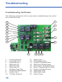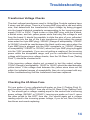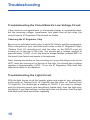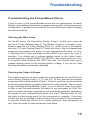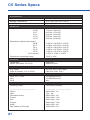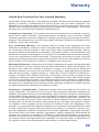
1
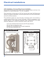
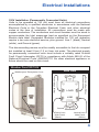
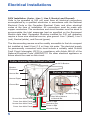
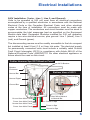
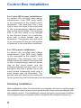
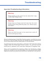
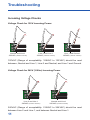
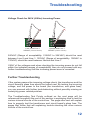
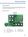
End User Disclaimer
End User Disclaimer:
United Spa Controls systems have absolutely no end user serviceable
parts. United Spa Controls does not authorize attempts by the spa owner/
user to install or repair/service any United Spa Controls products.
Non-qualified users should never open or remove covers, as this will
expose dangerous voltage points and other serious risks.
Non-qualified users should not attempt to make changes to the topside’s
programming, as mis-programming can result in malfunction or possible
damage.
Please contact your dealer or a locally licensed service center for service
and technical support.
This installation and service manual is provided solely to aid qualified spa
service technicians in installing, setting up, and troubleshooting spas with
United Spa Controls systems.
1
Table of Contents
End User Disclaimer . . . . . . . . . . . . . . . . . . . . . . . . . . . . . 1
Electrical Installations . . . . . . . . . . . . . . . . . . . . . . . . . . . . 3
120V Cord and Plug Connected . . . . . . . . . . . . . . . . . . 3
120V Permanently Connected . . . . . . . . . . . . . . . . . . . 4
240V Installation - 4-Wire . . . . . . . . . . . . . . . . . . . . . . . 5
240V Installation - 3-Wire (No Neutral) . . . . . . . . . . . . . 6
Control Box Installation . . . . . . . . . . . . . . . . . . . . . . . . . . 7
Finishing Installation . . . . . . . . . . . . . . . . . . . . . . . . . . . . . 9
Troubleshooting . . . . . . . . . . . . . . . . . . . . . . . . . . . . . . . 10
Important Troubleshooting Information . . . . . . . . . . . . 10
Incoming Voltage . . . . . . . . . . . . . . . . . . . . . . . . . . . . 11
Troubleshooting Test Points . . . . . . . . . . . . . . . . . . . . 13
Transformer & 2A Glass Fuse . . . . . . . . . . . . . . . . . . . 14
Low Voltage Circuit & Light Circuit . . . . . . . . . . . . . . . 15
Pumps/Blower/Ozone . . . . . . . . . . . . . . . . . . . . . . . . . 16
Heating Circuit . . . . . . . . . . . . . . . . . . . . . . . . . . . . . . 17
Replacing Relays . . . . . . . . . . . . . . . . . . . . . . . . . . . . . . . 18
Wiring Diagram . . . . . . . . . . . . . . . . . . . . . . . . . . . . . . . . 19
C5 Series Specs . . . . . . . . . . . . . . . . . . . . . . . . . . . . . . . . 21
Warranty . . . . . . . . . . . . . . . . . . . . . . . . . . . . . . . . . . . . . . 22
2
Electrical Installations
120V Installation (Cord and Plug Connected Units):
Equipment Modules provided with a factory installed power cord are to be
plugged into a grounding type, 120 volt, receptacle.
The connection of the plug to a 240 volt service will cause the Equipment
Module to operate improperly, create the potential for an electrical hazard,
and will void the warranty.
The electrical supply for cord and plug connected units must include a
suitably rated Ground Fault Circuit Interrupter (GFCI) in compliance with
Article 680-42 of the National Electrical Code. ANSI/NFP70. No other
electrical appliance or fixture should be used on this circuit.
• Use only dedicated electrical line with 20 amp breaker.
• Do not use an extension cord.
• Always use a weatherproof covered receptacle.
• Do not bury the power cord.
Weather Proof GFCI Kit
Back View
Weatherproof Receptacle Cover
LINE
Ground
Spa Power Cord
3
120V GFCI
Incoming Neutral from Main Panel (White)
Incoming Power from Main Panel (Black)
LOAD
Electrical Installations
120V Installation (Permanently Connected Units):
Units to be operated at 120 volt must have all electrical connections
accomplished by a qualified electrician in accordance with the National
Electrical Code or the Canadian Electrical Code, and other electrical
codes at the time of installation. All connections must be made with
copper conductors. The conductors and circuit breaker must be sized to
accommodate the total amperage load as specified on the Equipment
Module data label. Equipment Modules installed for 120 volt operation
require a two wire electrical service, plus ground. Line 1 (black), Neutral
(white), and Ground (green).
The disconnecting means must be readily accessible to the tub occupant
but installed at least 5 feet (1.5 m) from tub water. The electrical supply
for permanently connected units must include a suitably rated Ground
Fault Circuit Interrupter (GFCI) in compliance with Article 680-42 of the
National Electrical Code. ANSI/NFP70. No other electrical appliance or
fixture should be used on this circuit.
Weather Proof GFCI Kit
Back View
Weatherproof Receptacle Cover
Neutral to Spa (White)
Power to Spa (White)
LOAD
LINE
Ground
Power from
Main Panel
(Black)
Neutral from
Main Panel
(White)
120V GFCI
4
Electrical Installations
240V Installation (4 wire - Line 1, Line 2, Neutral, and Ground):
Units to be operated at 240 volt must have all electrical connections
accomplished by a qualified electrician in accordance with the National
Electrical Code or the Canadian Electrical Code, and other electrical
codes at the time of installation. All connections must be made with
copper conductors. The conductors and circuit breaker must be sized to
accommodate the total amperage load as specified on the Equipment
Module data label. Equipment Modules installed for 240 volt operation
require a three wire electrical service, plus ground. Line 1 (black), Line 2
(red), Neutral (white), and Ground (green).
The disconnecting means must be readily accessible to the tub occupant
but installed at least 5 feet (1.5 m) from tub water. The electrical supply
for permanently connected units must include a suitably rated Ground
Fault Circuit Interrupter (GFCI) in compliance with Article 680-42 of the
National Electrical Code. ANSI/NFP70. No other electrical appliance or
fixture should be used on this circuit.
Cuttler Hammer Spa GFCI Breaker Panel
GFCI Breaker
Breaker
Enclosure
Neutral Bar
Bottom View of GFCI
Power to Spa
Neutral Pigtail
Ground Bar
Neutral to Spa
Ground from Main Panel
Power from Main Panel
Neutral from Main Panel
Power from Main Panel
5
Hard Wired Neutral
to Neutral Bar
Power to Spa
Neutral to Spa
Power to Spa
Ground to Spa
Electrical Installations
240V Installation (3 wire - Line 1, Line 2, and Ground):
Units to be operated at 240 volt must have all electrical connections
accomplished by a qualified electrician in accordance with the National
Electrical Code or the Canadian Electrical Code, and other electrical
codes at the time of installation. All connections must be made with
copper conductors. The conductors and circuit breaker must be sized to
accommodate the total amperage load as specified on the Equipment
Module data label. Equipment Modules installed for 240 volt operation
require a two wire electrical service, plus ground. Line 1 (black), Line 2
(red), and Ground (green).
The disconnecting means must be readily accessible to the tub occupant
but installed at least 5 feet (1.5 m) from tub water. The electrical supply
for permanently connected units must include a suitably rated Ground
Fault Circuit Interrupter (GFCI) in compliance with Article 680-42 of the
National Electrical Code. ANSI/NFP70. No other electrical appliance or
fixture should be used on this circuit.
Cuttler Hammer Spa GFCI Breaker Panel
GFCI Breaker
Breaker
Enclosure
Neutral Bar
Bottom View of GFCI
Power to Spa
Neutral Pigtail
Ground Bar
Ground from Main Panel
Power from Main Panel
Neutral from Main Panel
Power from Main Panel
Hard Wired Neutral
to Neutral Bar
Power to Spa
Power to Spa
Ground to Spa
6
Control Box Installation
Mounting and Plumbing Considerations
The C5 control box is made for above ground portable hot tubs. As such
it is an indoor unit, meant to be mounted inside of the portable hot tub’s
enclosure. Water may flow through the heater in either direction, as long
as the water is being pushed through it (plumbed up to the discharge of
the pump). Plumbing the heater up to the suction of the pump will not allow
the heater to operate.
Temperature Sensor Installation
The C5 control box comes with a 1/4” diameter temperature sensor. Its
probe is meant to be installed into a thermowell which itself should be
installed mid-water level in the hot tub to provide the most accurate
temperature reading. After installing the temperature sensor probe, be
sure to plug the connector on the end of the cable into the temperature
sensor receptacle on the control box. The included sensor is carefully
calibrated to it’s cable’s length, and therefore must in no way be altered or
shortened/lengthened.
Equipment Connection
The Circulation Pump receptacle is for circulation pumps (rated 2A or
less). If your pump does not match this description it must be connected to
the Pump-1 receptacle and used as Pump-1. See page 11 for an important
note on how to wire the Circulation Pump cord for timed operation!
The C5 control uses the red wire for low-speed operation of Pump-1 and
Pump-2. Connecting a single speed pump as Pump-1 for both operating
the jets and heating/filtration is not recommended, but if you must use a
single speed pump for both, you must connect the red and black wires of
the pump cable together up to the high speed terminal on the back of the
pump’s motor to both operate jets and heat/filter.
If you are connecting an air blower or third pump to the Auxiliary
receptacle, then if there is a two speed Pump-2 it must be wired for single
speed (no red wire) operation at the back of the motor.
7
Control Box Installation
The Pump-1 and Pump-2 receptacles
are pre-wired for 240V. The Ozone,
Circulation Pump, Auxiliary, Audio,
and Gas (on the C5-G) receptacles are
all pre-wired for 120V.
Place wire on
Neutral to make
receptacle 120V
NEUTRAL
LINE-2
These receptacles are all dyed different
colors, and have white wires striped
with their respective receptacle’s color.
To change the voltage of a receptacle
simply move it’s correspondingly color
striped white wire at the power lugs from
Neutral to Line 2 to convert to 240V, or
from Line 2 to Neutral to convert to 120V.
Place wire on
Line-2 to make
receptacle 240V
LINE-1
The Light receptacle is wired for industry standard 12V lighting, up to
0.9A.
Power Installation
For 4-wire 240V power installations:
As shown, the included dual-voltage
transformer’s 2-pin AMP plug needs
to be connected to the board’s 240V
receptacle. The incoming Line-1,
Line-2, and Neutral wires will need to
be connected to the correspondingly
labeled power lugs on the circuit
board. The ground wire will need to
be connected to the ground lug that is
fastened to the aluminum enclosure.
NEUTRAL
LINE-2
LINE-1
F4
2A FUSE
240V
J7
120V
J8
J5
See the following page for information
on 3-wire 240V and 120V power
installations...
8
Control Box Installation
For 3-wire 240V power installations:
As shown, the included dual-voltage
transformer’s 2-pin AMP plug needs
to be connected to the board’s 240V
receptacle. The incoming Line-1 and
Line-2 wires will need to be connected
to the correspondingly labeled power
lugs on the circuit board. The incoming
Line 2 will also need to be brought
to the Neutral power lug (commonly
done with a short jumper wire as
illustrated). The ground wire will need
to be connected to the ground lug that
is fastened to the aluminum enclosure.
NEUTRAL
LINE-2
LINE-1
F4
2A FUSE
240V
J7
120V
J8
J5
For 120V power installations:
NEUTRAL
As shown, the included dual-voltage
transformer’s 2-pin AMP plug needs
LINE-2
to be connected to the board’s 120V
receptacle. The incoming Line-1 and
LINE-1
Neutral wires will need to be connected
to the correspondingly labeled power
lugs on the circuit board, and the
incoming Neutral will also need to be
brought to the Line 2 power lug on the
circuit board (commonly done with a
short jumper wire as illustrated). The
ground wire will need to be connected
to the ground lug that is fastened to the aluminum enclosure.
F4
2A FUSE
240V
J7
120V
J8
J5
Finishing Installation
After installation of the C5 control box is complete, its time to read through
the installation manual and user’s guide booklet that comes packaged with
the topside control. The installation manual will guid you through installing
and programming the topside which completes the installation process.
9
Troubleshooting
Important Troubleshooting Information
Warning:
When working on the control box be aware that it may
contain high voltage wiring.
Warning:
Always keep your fingers and tools away from the circuit
board and any wiring while the power is on. Serious injury
may result!
Warning:
Make sure that the power to the control box is shut off
before touching any wiring.
When troubleshooting a United Spa Controls system, no matter how minor
the issue is, the first things that must be checked are the incoming power
to the control board and the output power of the transformer.
You will need to set your multi-meter or voltmeter for AC Volts when testing
voltages within the United Spa Controls system. You will only set your
multi-meter or voltmeter to DC Volts when testing the IC Regulator Chip.
Once you’ve completed the incoming voltage and transformer voltage
checks as outlined on the next few pages, you can proceed with further
diagnosis using the test points and instructions outlined later in this section.
10
Troubleshooting
Incoming Voltage Checks
Voltage Check for 120V Incoming Power:
NEUTRAL
NEUTRAL
NEUTRAL
LINE-2
LINE-2
LINE-2
LINE-1
LINE-1
LINE-1
Neutral and Line-1
120VAC (108VAC-132VAC)
Line-2 and Line-1
120VAC (108VAC-132VAC)
Line-1 and Ground
120VAC (108VAC-132VAC)
120VAC (Range of acceptability: 108VAC to 132VAC) should be read
between; Neutral and Line-1, Line-2 and Neutral, and Line-1 and Ground.
Voltage Check for 240V (3-Wire) Incoming Power
NEUTRAL
NEUTRAL
LINE-2
LINE-2
LINE-1
LINE-1
Line-2 and Line-1
240VAC (216VAC-264VAC)
Neutral and Line-1
240VAC (216VAC-264VAC)
240VAC (Range of acceptability: 216VAC to 264VAC) should be read
between Line-2 and Line-1, and between Neutral and Line-1.
11
Troubleshooting
Voltage Check for 240V (4-Wire) Incoming Power
NEUTRAL
NEUTRAL
LINE-2
LINE-2
LINE-1
LINE-1
Line-2 and Line-1
240VAC (216VAC-264VAC)
Neutral and Line-1
120VAC (108VAC-132VAC)
240VAC (Range of acceptability: 216VAC to 264VAC) should be read
between Line-2 and Line-1. 120VAC (Range of acceptability: 108VAC to
132VAC) should be read between Neutral and Line-1.
If ANY of the voltages read when checking the incoming power do not fall
within the indicated ranges of acceptability, then do not proceed with any
further troubleshooting until the incoming power issue is corrected.
Further Troubleshooting
If the system passes the incoming voltage check, the transformer and the
circuit boards’s glass fuse should be tested next. By testing the incoming
voltage, and the power to the board (the transformer, and glass fuse),
you can proceed with further troubleshooting without possibly missing an
underlying power related problem.
The Troubleshooting Test Points outlined on the next page will be
referenced throughout the rest of this section in explaining how to test the
various internal circuits of the control box. The page after next will explain
how to properly test the transformer and circuit board’s glass fuse. The
pages that follow that will explaining trouble shooting the other various
circuits of the control box.
12
Troubleshooting
Troubleshooting Test Points
The following test points will be used when troubleshooting the control
box’s internal circuits:
20
1
19
2
18
3
17
4
16
15
5
14
6
7
13
8
12
10 20 30 40 50 60 70 80 90 10 -
13
Incoming Neutral
Incoming Line-2
Incoming Line-1
20A Fuse (F1)
20A Fuse (F2)
20A Fuse (F3)
2A Glass Fuse (F4)
Transformer Receptacle
Heater Line-2
T18/Gas Terminal
11 10
11 12 13 14 15 16 17 18 19 20 -
9
Heater Line-1
IC Regulator Chip
Pump-2 Hi-Speed Power
24Hr Circ & Audio Power
Aux/Pump-2 Lo-Speed Power
Pump-1 Lo-Speed/Timed Circ Power
Pump-1 Hi-Speed Power
Light (black wire)
Light (white wire)
Ozone Power
Troubleshooting
Transformer Voltage Checks
The dual-voltage transformers used in United Spa Controls systems have
6 wires, and two plugs. There is a 2-prong AMP plug with a red and white
wire, that determines the transformer’s input voltage by being plugged
into the board’s labeled receptacle corresponding to the incoming power
supply (120V or 240V). There is also a 4-pin AMP plug, with the a black,
a brown wires, and two yellow power wires that carry the voltage to and
from the board. It should be possible to slide the pins of your voltmeter/
multi-meter into the top of the 4-pin transformer plug (where the power
wires enter the 4-pin AMP plug). 240VAC (Range of acceptability: 216VAC
to 264VAC) should be read between the black and brown wires when the
2-pin AMP plug is plugged into the 240V receptacle, or 120VAC (Range
of acceptability: 108VAC to 132VAC) when the 2-pin AMP plug is plugged
into the 120V receptacle. If you are not getting a reading of the incoming
power within the acceptable range, and you’ve confirmed the incoming
voltage with the previous voltage checks, then the 2A Glass Fuse (Testing
Point 7) should be checked next.
If the incoming voltage checks out, proceed to test the output voltage.
12VAC (Range of acceptability: 12VAC to 14VAC) should be read between
yellow wires. If the voltage read between the yellow wires does not fall
within the indicated ranges of acceptability, then do not proceed with any
further troubleshooting until the transformer has been replaced.
Checking the 2A Glass Fuse
Put one probe of your voltmeter/multi-meter on Line-2 (Testing Point 2),
and the other on the RIGHT fuse clip of the 2A Glass Fuse (Testing Point
7). You should get a voltage reading equal to the control box’s incoming
power voltage (240VAC or 120VAC). Leaving one probe on Line-2, move
the other probe to the LEFT fuse clip. You should again get a voltage
reading equal to the incoming power voltage, if you do not, then the fuse
has blown and needs replacing.
14
Troubleshooting
Troubleshooting the Circuit Board’s Low Voltage Circuit
If the control is non-operational, or the topside display is completely blank,
but the incoming voltage, transformer, and glass fuse all test okay, the
circuit board’s IC Regulator Chip should be tested.
Checking the IC Regulator Chip
Be sure your voltmeter/multi-meter is set to DC Volts to test this component.
Place one probe of your voltmeter/multi-meter on the IC Regulator Chip’s
(Testing Point 12) mounting nut, and the other on the RIGHT most pin
coming out of the top of the chip. You should get a voltage reading of
approximately 15VDC. If not, the board’s bridge rectifier (marked BR1 on
the board) has failed and needs to be replaced.
Next, leaving one probe on the mounting nut, move the other probe to the
LEFT most pin coming out of the top of the chip. You should get a voltage
reading of approximately 5VDC. If not, the IC Regulator Chip itself has
failed and needs to be replaced.
Troubleshooting the Light Circuit
With the light turned on at the topside, place one probe of your voltmeter/
multi-meter on Testing Point 18 (Light-B) and the other on Testing Point
19 (Light-W). You should get a reading of 12VAC. If you read no voltage,
and the incoming power and transformer tested okay, then the light relay
has failed. If you read voltage, but the light does not function, then the light
bulb itself has failed and needs replacing.
15
Troubleshooting
Troubleshooting the Pumps/Blower/Ozone
If one or more of the pumps/blower/ozone are non-operational, re-check
that the code settings have been programmed correctly for the equipment
configuration. If programmed correctly, the main fuses and output voltages
should be checked.
Checking the Main Fuses
On the B7 board, the Circulation Pump, Pump-1, Audio, and ozone all
use the F1 Fuse (Testing Point 4). The Blower, Pump-3, or Pump-2 (LowSpeed) uses the F2 Fuse (Testing Point 5)., while Pump-2 (Hi-Speed)
uses the F3 Fuse (Testing Point 6). Check the fuse of the non-operational
component by putting one probe of your voltmeter/multi-meter on Line2 (Testing Point 2) and the other on the RIGHT fuse clip of the fuse in
question. You should get a voltage reading equal to the control box’s
incoming power voltage (240VAC or 120VAC). Leaving one probe on Line2, move the other probe to the LEFT fuse clip. You should again get a
voltage reading equal to the incoming power voltage, if you do not, then
the fuse has blown and needs replacing.
Checking the Output Voltages
The output power pin of each component are located at the top left of the
circuit board (Testing Points 13-17, and 20). To test, activate the desired
component that is being tested. Pump-1, Pump-2, and Aux can be activated
by simply pressing their corresponding button on the topside. The ozonator
is only activated during filtration cycles, so you’ll have to force the system
to filter to test the ozone power. Activation is not necessary for 24hr Circ
pump or Audio as these components are constantly powered. Next place
one probe of your voltmeter/multi-meter on Line-2 (Testing Point 2), and
the other on the testing point for the component in question. If the fuse
checks out, but no voltage is read on the power terminal of the component
in question (while the control is of course calling for that component to
run), then the relay for that component has failed.
16
Troubleshooting
Troubleshooting the Heating Circuit
If the heater is non-operational or the unit is not heating properly, re-check
that the code settings have been programmed correctly for the hot tub’s
heating configuration. If programmed correctly, the heating circuit should
be tested.
Testing the Heating Element
To test the heating element, you must first make sure the topside is calling
for heat (The display should be flashing the heat message - HEt). Then
place one probe of your voltmeter/multi-meter on Testing Point 11 (Heater
Line-1), and the other on Testing Point 9 (Heater Line-2). You should get a
voltage reading equal to the control box’s incoming power voltage (240VAC
or 120VAC). If that is the case, but the water is not getting heated, then the
heating element has failed/burnt-out/dry-fired.
If the voltage reading was not equal to the incoming power voltage, then
proceed with checking the heater relays.
Testing the Heating Relays
Place one probe of your voltmeter/multi-meter on Line-1 (Test Point 1), and
the other on Test Point 9 (Heater Line-2). You should get a voltage reading
equal to the control box’s incoming power voltage (240VAC or 120VAC). If
that is the case, proceed to the next test. If you read no voltage, however,
then the K10 relay has failed.
If the K10 relay checks out, place one probe of your voltmeter/multi-meter
on Line 2 (Test Point 2) and the other on Test Point 10 (T18/Gas Terminal).
You should get a voltage reading equal to the control box’s incoming power
voltage (240VAC or 120VAC). If that is the case, proceed to the next test. If
you read no voltage, however, then the K1 relay has failed.
If the K1 relay checks out, place one probe of your voltmeter/multi-meter
on Line 2 (Test Point 2) and the other on Test Point 11 (Heater Line-1). You
should get a voltage reading equal to the control box’s incoming power
voltage (240VAC or 120VAC). If you read no voltage, then the K9 relay
has failed.
17
Replacing Relays
Replacing Relays
Should a relay fail, it can be replaced by anyone qualified to solder or work
on electronics. Replacement relays should be available from anywhere
United Spa Controls products are sold.
Relay Locations
K6
K3
K7
K5
K2
K4
K9
K10 K20 K30 K40 K50 -
Temp Relay
Pump-1 Lo-Speed Relay
Pump-1 Hi-Speed Relay
Pump-2 Low & Aux Relay
Ozone Relay
K60 K70 K90 K10 -
K1
K10
Light Relay
Pump-2 Hi-Speed Relay
Hi-Limit-L1 Relay
Hi-Limit-L2 Relay
18
C5 Series Specs
Environmental
Operational Temperature
-0°F (-18°C) to 145°F (62°C)
Storage Temperature
-2°F (-19°C) to 175°F (79°C)
Humidity
Up to 80% RH, non condensing
Mechanical
Weight (without topside/cable)
C5-B
C5-T
C5-L
C5-G
C5-R
7.50 lbs. (3.40 kg)
8.15 lbs. (3.70 kg)
8.00 lbs. (3.63 kg)
5.50 lbs. (2.49 kg)
9.00 lbs. (4.08 kg)
Dimensions (without tail peices)
C5-B
C5-T
C5-L
C5-G
C5-R
C5-R Heater
11.25”H x 15.50”W x 3.25”D
13.00”H x 15.50”W x 6.00”D
11.25”H x 20.50”W x 6.50”D
11.25”H x 12.75”W x 3.00”D
11.25”H x 12.75”W x 3.00”D
6.00”H x 15.50” x 3.25”D
Dimensions (mounting holes)
13.25” x 2.63”
Enclosure
Control Box
Heater (No heater on C5-G)
Aluminum
Stainless Steel
Certifications
ETL Listed
(USA & Canada - File: 119733)
UL STD 1563 - 5th Edition
CSA C22.2 NO. 218.1
Minimum Heater Flow
C5-B, C5-T, C5-R
C5-L
C5-G
25 GPM Minumum
15 GPM Minumum
N/A
Electrical
Incoming Power
120V/240V 50/60Hz
-----------------------------------------Ozone
Light
Circulation Pump
Pump-1
Aux
Pump-2
Audio
Gas Heater (C5-G only)
-----------------------------------------240V/120V - 1A
12V - .9A
240V/120V - 2A
240V/120V - 12A
240V/120V - 12A
240V/120V - 12A
240V/120V - 4A
120V/240V - 1A
21
Warranty
United Spa Controls One Year Limited Warranty
United Spa Controls warrants, to the original purchaser, the Spa Control Equipment against
defects in materials or workmanship for a period of one year from date of purchase. The
obligation of this warranty shall be limited to repairing or replacing the part, which in the
opinion of the company shall be proved defective in materials or workmanship. This limited
warranty does not include the limitations described below.
Limitations of Coverage: This warranty does not cover failures due to: damage, freezing,
power failure, power reduction, unusual atmospheric conditions, rust or corrosion, repairs
necessary because of operator negligence improper re-packaging and damage incurred in
shipping. This warranty does not cover thermostat calibration, plumbing, expendable items
(gaskets, o-rings, filter cartridges).
Acts Invalidating Warranty: This warranty shall be invalid if this equipment has been
subjected to alterations, misuses or abuse, improper water chemistry maintenance or used
for commercial purposes (used in other than single family household purposes). Misuse
and abuse shall include application installation or operation outside of the environment and
limitations for which it was designed, or other than in accordance with United Spa Controls
or the spa manufacturer printed instructions. This warranty shall also be invalid if the spa
equipment is damaged by earth or ground fill movement, fire, flood, wind, lightning, by Act of
God, accident, or by intentional, reckless, or negligent acts any person.
Warranty Performance: All warranty service and/or replacement of parts must be performed
by an individual or service company that has been authorized by United Spa Controls. The
purchaser may obtain the benefits of warranty coverage on a failed part by having the
servicing company remove the part and send it for inspection, along with proof of purchase
and field service report, freight pre-paid, to: United Spa Controls 2480-B N. Glassell St.,
Orange, CA 92865 If the failure is covered by the warranty, there will be no charge for the
repaired or replacement part. Removal charges, re-installation charges, and freight charges
to and from United Spa Controls of the failed part shall be the purchaser’s responsibility.
Any such warranty replacement or repair shall be subject to the terms and condition of this
warranty for the remainder of the original period of coverage. United Spa Controls reserves
the right to inspect the malfunction or defect on location.
Disclaimers, Legal Remedies: United Spa Controls shall not be liable for the loss of use
of any equipment. This warranty is in lieu of all other expressed warranties obligations or
liabilities, any implied warranty of merchantability, shall be limited in duration to the duration
of this written limited warranty. Any action for breach of warranty hereunder, including but
not limited to, any applied warranty of merchantability must be brought within a period of 12
months from date of purchase. Some states do not allow limitations on how long an implied
warranty lasts, so the above limitation may not apply to you. No agent, representative, dealer
or employee of the company has the authority to increase or alter the obligations of this
warranty. In no case shall the company be liable for any incidental or consequential from state
to state. United Spa Controls does not authorize any person or company to assume for it
any other obligation or liability in connection with the sale, application, engineering, damages
for breach of this of any other warranty, expressed or implied, whatsoever. Some states do
not allow the exclusion or limitation of incidental or consequential damages, so the above
limitation or exclusion may not apply to you. This warranty gives you specific legal rights, and
you may also have other rights which vary installation use, removal, return, or replacement of
it’s systems: and no such representations are binding on United Spa Controls.
22
United Spa Controls
2480-A N. Glassell St.
Orange, CA 92865
Web:
E-mail:
Phone:
Fax:
UnitedSpaControls.com
[email protected]
714-282-1117
714-282-8684
©2014 United Spa Controls. All rights reserved.