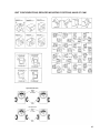
1
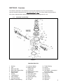
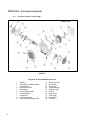
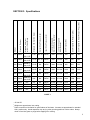
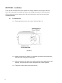
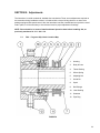
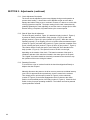
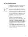
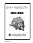
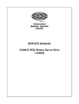
INSTALLATION & SERVICE MANUAL
INTERMITTOR®
ROLLER DIAL INDEX DRIVES
WARNING
This is a controlled document. It is your responsibility to deliver this information to the end user of the CAMCO or
FERGUSON product. Failure to deliver this could result in your liability for injury to the user or damage to the
machine. For copies of this manual, call your Customer Service Representative at 800-645-5207
INTRODUCTION
INTRODUCTION
This manual is supplied to aid in the installation and maintenance of your Fergusonbrand index drive.
When contacting Industrial Motion Control, please have the serial number of your unit
available. This number can be found on the serial number tag.
To determine the model number and the ratio of a Ferguson reducer, refer to the tag
which is located on the reducer housing. If the reducer is by another manufacturer,
refer to that manufacturer's nametag located on the reducer housing.
Unit configurations, reducer mounting positions, and hand of cam nomenclature can
be found inside the back cover of this manual. These will aid in describing your unit.
Industrial Motion Control provides factory rebuild or repair services at our centrally
located Wheeling, IL facility. Industrial Motion Control can also provide technicians or
engineers for field service calls worldwide.
If you have any questions or problems, please feel free to contact our
Technical Service Department at:
1-800-645-5207 or 1-847-459-5200, FAX: 1-847-459-3064,
or EMAIL: [email protected].
If you need to contact a sales representative in your area, you can log on to our web
site: www.camcoindex.com and go the section labeled "Find a local Rep" to find the
sales office that is nearest to you.
At Industrial Motion Control, it is our policy to provide the highest quality products that
meet or exceed our customer's requirements. In order to achieve this commitment,
Industrial Motion Control has documented its policies and procedures to be in
compliance with ISO-9001.
Table of Contents
Section
1.
2.
Page
General Information . . . . . . . . . . . . . . . . . . . . . . . . . . . . . . . . . . . . . . . . . . . . . . . .2-4
1.1.
Warranty . . . . . . . . . . . . . . . . . . . . . . . . . . . . . . . . . . . . . . . . . . . . . . . . . . . . . .2
1.2.
Safety . . . . . . . . . . . . . . . . . . . . . . . . . . . . . . . . . . . . . . . . . . . . . . . . . . . . . .2,3
1.3.
Operating Environment . . . . . . . . . . . . . . . . . . . . . . . . . . . . . . . . . . . . . . . . . . .3
1.4.
Ordering Replacement Parts . . . . . . . . . . . . . . . . . . . . . . . . . . . . . . . . . . . . . . .3
1.5.
Requesting Service . . . . . . . . . . . . . . . . . . . . . . . . . . . . . . . . . . . . . . . . . . . . . .4
1.6.
Returning a Unit for Repair . . . . . . . . . . . . . . . . . . . . . . . . . . . . . . . . . . . . . . . .4
Overview . . . . . . . . . . . . . . . . . . . . . . . . . . . . . . . . . . . . . . . . . . . . . . . . . . . . . . . .5,6
2.1.
Intermittor Location Map & Parts List . . . . . . . . . . . . . . . . . . . . . . . . . . . . . . . . .5
2.2.
Reducer Location Map & Parts List . . . . . . . . . . . . . . . . . . . . . . . . . . . . . . . . . .6
3.
Specifications . . . . . . . . . . . . . . . . . . . . . . . . . . . . . . . . . . . . . . . . . . . . . . . . . . . . . .7
4.
Installation . . . . . . . . . . . . . . . . . . . . . . . . . . . . . . . . . . . . . . . . . . . . . . . . . . . . . .8-10
5.
Adjustments . . . . . . . . . . . . . . . . . . . . . . . . . . . . . . . . . . . . . . . . . . . . . . . . . . . .11-14
5.1.
6.
FSC…Ferguson Slip Clutch . . . . . . . . . . . . . . . . . . . . . . . . . . . . . . . . . . . .11-14
Maintenance . . . . . . . . . . . . . . . . . . . . . . . . . . . . . . . . . . . . . . . . . . . . . . . . . . . . . .15
6.1.
Using Correct Lubricants . . . . . . . . . . . . . . . . . . . . . . . . . . . . . . . . . . . . . . . . .15
6.2.
Changing Oil . . . . . . . . . . . . . . . . . . . . . . . . . . . . . . . . . . . . . . . . . . . . . . . . . .15
7.
Troubleshooting . . . . . . . . . . . . . . . . . . . . . . . . . . . . . . . . . . . . . . . . . . . . . . . . .16,17
8.
Repair and Replace . . . . . . . . . . . . . . . . . . . . . . . . . . . . . . . . . . . . . . . . . . . . . .18-28
9.
8.1.
Cam Follower Replacement . . . . . . . . . . . . . . . . . . . . . . . . . . . . . . . . . . .18-20
8.2.
Oil Seal Replacement . . . . . . . . . . . . . . . . . . . . . . . . . . . . . . . . . . . . . . . .21,22
8.3.
Reducers . . . . . . . . . . . . . . . . . . . . . . . . . . . . . . . . . . . . . . . . . . . . . . . . .22-25
Things to Avoid . . . . . . . . . . . . . . . . . . . . . . . . . . . . . . . . . . . . . . . . . . . . . . . . . . . .26
REFERENCE: Unit configurations, Reducer Mtg Positions, Hand of Cam Drawing . . . . . .27
1
SECTION 1: General Information
The Industrial Motion Control (IMC) Intermittor is engineered and manufactured to very high tolerances
which necessitate careful inspection and maintenance.
Some users of indexing drives have the facilities and trained personnel to accomplish service repair. You
must determine the extent to which intricate servicing should be done in your own facility. When in doubt,
IMC recommends that IMC trained servicemen make the repairs.
1.1.
Warranty - Products are warranted as follows:
1.1.1. Our products are warranted for one (1) year from the date of shipment to be free
from defects in workmanship and materials. The foregoing warranty is exclusive
and in lieu of all other warranties, whether written or orally expressed or implied
and there are no warranties of merchantability or fitness for particular use.
1.1.2. Our obligation under the foregoing is limited to replace free of charge, including the
lowest transportation cost, but not including installation or any other charges, any
part that our inspection shows to be defective provided that the part was properly
installed, suitably maintained and not subject to misuse or abuse, and further
provided that the defective parts are returned to our plant within one (1) year after
delivery by us. Written permission for such return must first be obtained from IMC.
A complete explanation is required of the alleged defects and circumstances.
1.2.
Safety – Read and follow all Warnings and Cautions prior to any service or repair.
1.2.1. Intermittors should not be started and stopped at high speed during the transfer
phase of the cam. This can cause serious damage to the Intermittor and reduce
the cam follower life. For cycling during setup or jog mode, speed must be
reduced to 25% of the normal operating speed. The use of an E-stop for
purposes other than emergencies is not recommended. A cycle stop button should
be incorporated into the system controls. Please consult Industrial Motion Control’s
Wheeling factory for additional information.
1.2.2. Always disconnect power and lockout the source before working on these units.
1.2.3. All input and output connections should be backlash free. Use friction lock type
shaft couplings such as taper lock bushings, split and clamped hubs, etc., in the
input and output drive train. There should be no loose keys, set screws, etc.
2
SECTION 1: General Information (continued)
1.2.4. Reducers should be of minimum backlash variety and directly coupled with a
backlash-free connection. If line shafts are used, they must be sized for severe
reversing loads.
1.2.5. When using chain drives, incorporate an idler to eliminate any slack. (Do not use
spring-loaded idlers.) As the cam motion stops and starts, any slack in the drive
changes sides. It is necessary to maintain a constant speed of the input shaft.
Loose belts or chains will cause inertial over-run, causing distorted acceleration
and deceleration characteristics which may cause damage to the unit. Belts and
chains must be sized for severe reversing loads.
1.2.6. Ferguson does not provide guarding for moving parts, such as dials, handwheels,
switch cams, etc. Numerous pinch points do exist on this equipment and the
possibility exists of being struck by a moving part. Since this product is expected to
become part of a further developed machine, it is the customer’s responsibility to
add safety fencing, guarding, light curtains or other protection devices, as
necessary, to protect personnel and property.
NOTE: In the event the unit is damaged, contact Industrial Motion Control’s
Wheeling factory or your local representative, for proper reconditioning or
repair (see sections 1.5 Requesting Service or 1.6 Returning a Unit for Repair).
1.3.
Operating Environment – This machine is intended to operate in a clean environment.
Excessive coolant, chips, dust dirt or debris can adversely affect its performance and life.
If this machine does operate in a dirty environment periodic cleaning must be practiced
and careful inspection of seals and accessories is necessary.
1.3.1. For extended storage, remove vents and fill with proper oil. (Refer to section 6)
1.4.
Ordering Replacement Parts – When ordering parts, always provide the following
information:
1.4.1. The serial number shown on the nameplate.
1.4.2. The part name and/or the description listed in the manual.
1.4.3. The part numbers shown on the bill of material or assembly drawings.
3
SECTION 1: General Information (continued)
1.5.
Requesting Service – Call our Technical Service Department in Wheeling, IL at
1-800-645-5207 or 847-459-5200 between 8:00AM and 4:00PM CST. When requesting
service, always provide the following information:
1.5.1. The serial number shown on the nameplate. (Refer to Inside Front Cover)
1.5.2. A clear description of the problem, including as much detail as possible of the
circumstances leading up to the problem.
1.6.
Returning a Unit for Repair – Please contact the Repair Department in Wheeling,
Illinois at (847) 459-5200 for a "Return Material Authorization" Number (RMA#).
The following information is required of a unit for repair, conversion or warranty.
1. Purchase order number
2. Customer name
3. Customer billing address
4. Customer shipping address
5. Person to contact, upon inspection, with delivery and price.
6. Telephone number
7. Model number (located on name plate)
8. Serial number (located on name plate)
9. Description of defects, problems or circumstances.
The IMC Repair Department will assess repairs by phone and estimate inspection fees or
repair costs.
Non-warranty inspection fees will vary depending on the size of the unit and optional
equipment mounted. These fees apply only if customer decides not to repair or replace
subject unit.
Please return IMC equipment only (remove sprockets, pulleys, etc). This will reduce the
amount of disassembly time (saving customer cost on labor) and will provide faster
evaluation for quoting price and delivery of repair or conversion. Oil must be drained
before shipping.
Package unit to protect it from weather or damage during shipping. Place the
(RMA#) on the outside of the packaging for prompt service.
Ship Warranty units via surface freight collect. Ship Non-Warranty units to IMC
transportation prepaid. IMC will not accept collect shipments on non-warranty repairs
Ship to:
4
Industrial Motion Control, LLC
1444 South Wolf Road
Wheeling, Illinois 60090 - USA
SECTION 2: Overview
The sketches contained in this document are for illustrative purposes only. They are intended to
represent standard components and may not be shown to scale. The various models may be different
than shown, depending upon options chosen or the particular configuration of a unit.
2.1.
Intermittor Location Map
FIGURE 1
Intermittor Parts List
1.
2.
3.
4.
5.
Housing
Cam
Roller Gear Hub
Roller Gear (Output) Shaft
Bearing Ring &
Spacer Shims
6. Oil Seal
7. Timken Bearing
8. Cam Followers
9. Locking Set Screw
10. Bottom Timken Bearing
11. Locknut & Washer
12. Bottom Cover for
Output Shaft
13. Cap Screws
14. Bottom Housing Cover
15. Cap Screws
16. Cam (Input) Shaft
17. Drive Key (Cam)
18. Eccentric Bushing
19. Shim Pack
20. Oil Seal
21.
22.
23.
24.
25.
26.
27.
28.
29.
30.
Timken Bearing
Locknut
Lockwasher
Cam Spacer – not required
for all drive codes
Front Access Cover
Air Vent
Pipe Plug
Cap Screws
Cap Screws
Top Cover
5
SECTION 2: Overview (continued)
2.2.
Ferguson Reducer Location Map
FIGURE 2
Ferguson “R” Series Reducer Parts List
1.
2.
3.
4.
5.
6.
7.
8.
9.
6
Housing
Ring Gear (& separate spider
for some units)
Pinion Worm Gear
Gear Spacer
Key for Indexer Shaft
Arrestor Washer
Lockwasher
Cap Screw Keeper
Cap Screw for Clamping Hub
10.
11.
12.
13.
14.
15.
16.
17.
18.
19.
Closed End Cap
Cap Screws
Shim Pack
Timken Bearing
Open End Cap
Oil Seal
Wear Sleeve
Cover Plate
Cap Screws
Oil Plugs
Output Shaft Torque Limiter
Input Shaft Torque Limiter
Lubrication Capacity
3
Main Oil Sump (Gallons)
Lubrication Capacity
3
Gear Reducer
Unit Weight with Reducer (LBS)
Unit Weight with Motor/Reducer Pkg. (LBS)
1 HP1
DTL10
R3FSC
4 GAL.
2.5 QTS.
200
250
300
1.5 HP
DTL10
R4FSC
4 GAL.
1.5 GAL.
450
550
625
1.5 HP
N/A
R4FSC
8 GAL.
1.5 GAL.
800
875
975
2.0 HP
N/A
R5FSC
9 GAL.
2.5 GAL.
1000
1150
1300
N/A
N/A
R5FSC
14 GAL. 2.5 GAL.
1500
1650
1800
N/A
N/A
R6FSC
15 GAL. 3.7 GAL.
2500
2700
3000
N/A
N/A
N/A
R6FSC
33 GAL. 3.7 GAL.
4750
4950
5250
R700
N/A
N/A
N/A
R7FSC
33 GAL. 6.5 GAL.
6000
6300
6650
R700
N/A
N/A
N/A
R7FSC
42 GAL. 6.5 GAL.
8750
10000
10500
R800
N/A
N/A
N/A
R8FSC
44 GAL. 10.5 GAL. 10000
10500
11050
123
R400
242
R400
243
R500
362
R500
363
R600
481
R600
482
722
723
MDB625
With 1 HP
MDB875
With 2 HP
MDB875
With 2 HP
MDB1125
With 5 HP
MDB1125
With 5 HP
MDB1125
With 5 HP
2
R300
Unit Weight (LBS)
Standard Reducer
122
Standard AC Motor
with Air Clutch/Brake
Model
2
Standard 180 Volt DC Motor
2
SECTION 3: Specifications
CHART 1
1
2
3
90 Volt DC.
Weights are approximate, less crating.
Refer to section on lubrication for specifications of lubricants. Amounts are approximate for standard
HM-1 position only. Actual capacities may vary by other mounting positions or drive codes. Always
check oil level site glass or plugs before topping off or refilling.
7
SECTION 4: Installation
These units are manufactured to meet a specific set of design parameters. Any change to the load,
size of dial, or speed of the camshaft may require a size change. No change can be made without
affecting other performance characteristics of the unit and, therefore, should not be done without
consulting the factory.
4.1.
To install the unit:
4.1.1. Rotate input shaft so cam is in center of dwell (see Figure 3).
FIGURE 3
4.1.2. Mount the Intermittor into position on a rigid base and secure with the largest size
bolts that will fit through the mounting holes.
4.1.3. Align the Intermittor with respect to the station positions before tightening bolts and
doweling. Use a dial indicator or other appropriate tool to insure alignment.
4.1.4. Tighten all mounting bolts securely and uniformly.
8
SECTION 4: Installation (continued)
4.1.5.
Install dowels.
4.1.5.1. Use a commercially available straight dowel of the appropriate size.
4.1.5.2. Drill a hole into the base to a depth of at least 1-1/2 times the diameter
of the dowel. Use a drill the same size as the pilot holes in the indexer
housing.
4.1.5.3. Line ream housing and base for press fit with dowel pin.
4.1.5.4. Install dowel pins into position. Leave some material exposed to
facilitate removal in the future, or use threaded dowel pins.
4.1.6.
Check the oil level of the sump and gear reducer prior to operating the unit.
4.1.6.1. Pay particular attention if the oil level is too high. If a unit has been idle
for some time since its manufacture, condensation may be present. If
condensation is noticed, the oil should be drained, the unit thoroughly
cleaned and re-filled with oil (see Chart 1 in Section 3 for capacities).
NOTE: If shot pins or leader guide pins in dies are used, the cam
should have been manufactured with a dwell relief in the cam.
If severe tangential or vertical loads exist, an anvil may be
required. For further information, consult your local Industrial
Motion Control Representative or the Technical Sales Department
at 1-800-645-5207 or 847-459-5200.
4.1.6.2. The unit’s sump must be filled with SAE 90 EP Gear or equivalent
meeting MIL-PRF-2105E and API Service Classification GL5 or GL6
before operation (see Chart 1 in Section 3 for capacities). An example
of this oil is Mobilube HD 80W-90. For extreme applications, use
Mobilube HD 85W-140 (consult your local representative to determine if
your application is extreme).
4.1.6.3. Bronze Gear Reducer oil must be SAE140 Steam Cylinder Oil meeting
AGMA #8 Compound, MIL SPEC, MIL-L-15016A; symbol 3150
(see Chart 1 in Section 3 for capacities). (Or manufacturer’s specified
oil if not a Ferguson manufactured reducer.)
4.1.6.4. Be sure optional controller is properly fused – refer to vendor’s manual.
9
SECTION 4: Installation (continued)
4.1.7. Check the adjustment of the switch cam if your unit has this option. To insure unit
stops in dwell, see Figure 3.
4.1.7.1.
A standard roller gear indexer is shown in Figure 3 with a Brake Cam &
Limit Switch shown with the keyway in the center of the dwell period. It
is necessary to phase the Brake Cam such that the input shaft of the
indexer stops during the dwell period of the index cycle while leaving
enough of the dwell period for the input shaft to accelerate to full speed
before leaving the dwell period.
4.1.7.2.
If the indexer has a drive code which causes multiple indexes per
camshaft revolution (i.e. X2, X3, etc… drive codes), additional lobe(s) on
the Brake Cam are required. The lobes will be equally spaced.
Therefore, phasing the one lobe of the Brake Cam to one dwell period
on the indexing cam will, in most cases, cause the other lobes to be
correctly phased with the other dwell periods.
NOTE: Controllers are normally shipped loose and brake cam /
limit switches are mounted to the unit. However, neither are set or
adjusted at the factory. Limit switch and cam must be set to initiate
the stopping cycle. Controller must be set for the load & speed of
the application per instruction in the vendor’s manual.
NOTE: The switch and brake cam commonly provided to initiate
the stop cycle can not be used to indicate “on station.” A second
switch and brake cam should be ordered for this purpose.
10
SECTION 5: Adjustments
The Intermittor is a solid mechanical, backlash-free mechanism. There are no adjustments required on
the Intermittor during installation unless it is furnished with a torque limiting device or a motor drive
package equipped with speed control. After the Intermittor has been installed and set up with the users’
load in place, it will be necessary to check these items for proper adjustment & settings.
NOTE: Drive should be in center of dwell and dowel pinned to base before installing dial, as
previously mentioned in 4.1.1. & 4.1.5.4.
5.1.
FSC… Ferguson Slip Clutch Location Map
1.
Housing
3.
Body & Cone
4.
Thrust Bearing
5.
Silicon Spring
6.
Adjusting Nut
7.
Guide Pin
8.
Spool
9.
Ball Plunger
10. Liner Bushing
11. Setscrew
12. Pipe Plug
FIGURE 4
11
SECTION 5: Adjustments (continued)
5.1.1. Clutch Adjustment Description
The clutch must be adjusted to prevent any slippage during normal operation to
prevent shock loading. It should also not be adjusted so tight as to be able to
damage the indexer during a jam or overload. However, it is best to err on the side
of being tighter than required. The proper setting for the clutch is determined by
gradually tightening the clutch adjusting nut until the clutch no longer slips in either
direction during a complete, fully loaded index cycle at normal speed.
5.1.2. Shut-off Spool Use & Adjustment
The shut-off spool (number 8, Figure 4) is attached to body (number 3, Figure 4)
by means of shallow round threads in body (number 3, Figure 4) and a ball
plunger (number 9, Figure 4) in spool (number 8, Figure 4). When the clutch is
operating normally (i.e. not slipping), there is no relative movement between spool
(number 8, Figure 4) and main body (number 3, Figure 4) and the remainder of the
clutch, including the spool (number 8, Figure 4) driven by pin (number 7, Figure 4).
This relative rotation causes the spool to move along the screw threads on the
body (number 3, Figure 4). The spool will move to the left or to the right,
depending on the rotation of the clutch. This lateral movement of the spool is
intended to activate a limit switch arm located in the center groove in the spool.
The "tripped" limit switch should be electrically connected to the controls to stop
the operation of the motor driving the indexer.
5.1.3. Resetting Procedure
To recover from a jam or overload in which the clutch has slipped sufficiently to
displace the shut-off spool:
Manually disconnect the power to the drive motor to prevent an accidental start-up
(use O.S.H.A. approved lockout procedures), clear the cause for the overload.
Then simply push or pull the spool (number 8, Figure 4) on the main body
(number 3, Figure 4) to the thread engagement which is closest to the center
position on the threaded portion of the body (number 3, Figure 4). Check the limit
switch circuitry for proper operating conditions. The indexer can now be powered
up and production resumed.
12
SECTION 5: Adjustments (continued)
5.1.4. Clutch Adjustment Procedure
CAUTION: OPERATIING THE INDEXER WITH THE CLUTCH NOT ADJUSTED
CAN CAUSE IMMEDIATE AND SEVERE DAMAGE TO THE INTERNAL
COMPONENTS OF THE INDEXER.
a.
b.
Loosen cone point setscrew (number 11, figure 4).
Insert pins of spanner (figure 6) into holes of adjusting nut (number 6, figure 4),
and turn nut clockwise one notch in the adjusting nut. This will tighten the clutch.
NOTE: For heavy indexing loads or clutches on large units, it may be
necessary to increase the length of the spanner wrench to gain more leverage.
FIGURE 5
If clutch has not been adjusted for a long period of time, it may be necessary
to turn the nut counter-clockwise several turns, and tap the face of housing
(number 1, figure 4) towards the indexer with a rubber mallet to separate
(loosen) the tapers. Take note of the number of loosening turns so the
adjusting nut can be re-tightened to its original position.
c.
Re-tighten setscrew (number 11, figure 4) making sure it engages in adjusting
nut (number 6, figure 4) to prevent damage to screw threads.
NOTE: If setscrew (number 11, figure 4) is accidentally tightened on threaded
portion of adjusting nut (number 6, figure 4), it will raise a burr. Failure to
remove this burr will cause shearing of threads and jamming of nut of housing
(number 1, figure 4). To remove burr, remove setscrew (number 11, figure 4)
and rotate adjusting nut counter-clockwise until burr is in center of tapped hole
in housing (number 1, figure 4). Use a hand electric drill that fits freely into the
tapped hole. Drill into the adjusting nut (number 6, figure 4) sufficiently to
remove the burr.
There are (2) setscrews (number 11, figure 4). They are positioned so one
screw is half way between the slots in the nut when the other screw engages
the slot in the nut. This is to allow for fine adjustment of the clutch. DO NOT
use both screws at the same time as one screw will not be over a slot and will
cause damage to the screw threads.
13
SECTION 5: Adjustments (continued)
d.
Apply power to the unit and check for clutch slippage.
NOTE: When clutch is not slipping, entire clutch will rotate as a single unit.
When clutch is slipping body (number 3, Figure 4) will not rotate with the other
parts of the clutch. Small amounts of clutch slippage can be difficult to
determine. To aid in providing if the clutch is slipping, use a grease pencil or
felt tip marker and draw a line across face of nut (number 6, Figure 4) and
along body (number 3, Figure 4). If clutch is slipping, the line on nut (number 6,
Figure 4) and body (number 3, Figure 4) will move relative to each other.
DO NOT LET CLUTCH SLIP ANY LONGER THAN NECESSARY OR
CLUTCH MAY HEAT UP RESULTING IN UNPREDICTABLE OPERATION
AFTER IT COOLS.
e.
Repeat steps a through d until there is positively no clutch slippage.
5.1.5. Lubrication:
a. Clutches are grease packed at the factory and should not require additional
lubrication. If clutch is subject to consistent slippage and heating, remove pipe
plug (number 9, Figure 4) and insert your standard grease fitting, lubricate with
Lithium EP grease. Do not use air pressure gun!
14
SECTION 6: Maintenance
6.1.
Correct Lubricants – For the protection of the unit use only lubricants meeting the
specifications shown below in Chart 2. If you have any questions about a particular
lubricant feel free to call us at 1-800-422-8936.
6.2.
Changing Oil
6.2.1. All parts are oil splash lubricated except for isolated areas where grease fittings
will be supplied.
6.2.2. Maintain oil to the midpoint of the sight gauge or oil level & fill plug.
NOTE: The orientation of your unit will determine the exact quantity of oil
required.
6.2.3. Drain, flush and fill the unit in intervals of 2400 hours or at least yearly. If drive
operates at speeds above 300 RPM or at temperatures above 140 degrees F.,
increase oil change frequency to 6 months or 1200 hours intervals.
6.2.4. Service all grease fittings on 1-month intervals or every 200 hours of operation.
NOTE: In the majority of the applications, grease fittings are not supplied
since oil splash supplies the lubrication. Should grease be specified use
Lithium No.2.
Indexer Oil:
Use SAE 90 EP Gear oil or equivalent meeting MIL-PRF-2105E and
API Service Classification GL5 or GL6. For example, Mobilube HD 80W-90
Capacity:
See specifications in Chart 1 for your model.
Gear Oil:
Bronze Gear Reducer oil requires SAE 140 Steam Cylinder Oil,
meeting AGMA #8 Compound, MIL SPEC. MIL-L-15016A; symbol 3150
(Or manufacturer’s specified oil if not a Industrial Motion Control
manufactured reducer.)
Capacity:
See specifications in Chart 1 for your model.
CHART 2
15
SECTION 7: Troubleshooting
TROUBLESHOOTING GUIDE
Symptom
Solution
Backlash at output shaft
(in dwell)
Worn/damaged followers
Replace
Tight Stations
(torque required to rotate
cam shaft through tight
station is more than 1 1/2
times the loose station)
Bent cam followers
Replace; inspect holes in roller
gear shaft
Pitting of cam follower
outer race/cam track surface
Incorrect oil
Replace cam followers and fill
unit with correct oil
Fine magnetic metallic particles
in oil; appear bronze color
when in oil
Steel and iron worn from
bearing roller ends and cages
and cams surface (this is a
normal condition)
Flush out when replacing oil
A. End play in worm shaft
Contact Technical Services at
800-645-5207 or 847-459-5200.
B. Loose gear on camshaft.
Contact Technical Services at
800-645-5207 or 847-459-5200.
A. Worm-shaft bearings
pre-load.
Contact Technical Services at
800-645-5207 or 847-459-5200.
B. Incorrect alignment of
worm and gear.
Contact Technical Services at
800-645-5207 or 847-459-5200.
C. Excessive worm speed.
Reduce worm speed.
REDUCER:
Excessive Backlash
Overheating in Excess of 210°F
16
Cause
SECTION 7: Troubleshooting (continued)
TROUBLESHOOTING GUIDE
Symptom
OIL LEAKS AT:
Seals
Cause
Solution
Worn or damaged seal
and/or shaft surface
Replace seal; polish shaft
Shims
Damaged shim
Replace; apply “Loctite Aviation
Grade Sealant” to both sides
Cap Screws
Shim damaged between screw
hole and interior of housing
Replace gasket or shim; apply
“Loctite Aviation Grade
Sealant” to both sides
Holes drilled through
Remove screw, apply
“Loctite Threadlocker” and
re-install
Cover joints
Inadequate sealant
Remove, clean and
reassemble with silicone
rubber sealant
Oil service pipe fittings
Not properly sealed
Remove, clean and reinstall
with “Loctite Teflon Pipe
Sealant”
NOTE: In the event that damage is found, it is recommended that the unit be returned to the
factory for repair or that an Industrial Motion Control Serviceman make or supervise repairs in
your plant. Proper alignment and adjustment of the components are essential to their
performance and life.
17
SECTION 8: Repair and Replace
8.1 Cam Follower Replacement
8.1.1. Rotate camshaft to mid-dwell position. (See Figure 3)
8.1.2. Drain oil and remove front access cover.
8.1.3. Stand unit on end and remove bottom access cover to expose cam follower stud
locking fastener.
8.1.4. Determine cam follower design for your unit, and refer to the following instructions
(Figures 6 through 9). Then continue with step #8.1.5. below.
8.1.5. Clean sealant from access cover(s) and surfaces on housing.
8.1.6. Install access cover(s) with silicon rubber sealant, and tighten screws evenly.
8.1.7. Refill with oil.
18
SECTION 8: Repair and Replace (continued)
FOLLOWER NO. F-50 THROUGH F-400
DISASSEMBLY:
Remove setscrew and pull cam follower
from hole using a draw hammer secured
in tapped hole.
ASSEMBLY:
Clean the follower stud hole in the roller
gear hub and inspect for elongation,
which could cause backlash by failing to
support the stud at the top.
Place a socket head screw in pull hole
and strike its head - do not strike the
follower end cap when installing.
FIGURE 6
Apply a light coat of assembly grease to a new cam follower, orient so the setscrew and seat are in
line and install lightly against shoulder.
FOLLOWER NO. FM-50; FM-62; FM-75
DISASSEMBLY:
Remove jam nut, setscrew, follower and
nylon plug.
ASSEMBLY:
Clean the follower stud hole in the hub
and inspect for an out-of-round condition,
which could cause backlash by failing to
support the stud at the top.
Apply a light coat of assembly grease to
a new cam follower and install it firmly
against seat; loosen and retighten. Install
new nylon plug and tighten setscrew and
jam nut in place.
FIGURE 7
19
SECTION 8: Repair and Replace (continued)
FOLLOWER NO. FM-100 & FS100 - FS-400
DISASSEMBLY:
Remove locknut, setscrew and follower.
ASSEMBLY:
Clean the follower and stud hole in the
roller gear hub and inspect for
elongation, which could cause backlash
by failing to support the stud at the top.
Apply a light coat of assembly grease to
a new cam follower and install it firmly
against seat; loosen and retighten.
FIGURE 8
Install setscrew, tighten sufficiently to mark follower stud with setscrew point and remove setscrew.
Remove cam follower and drill a setscrew seat at the marked position deeply enough to make seat
diameter equal to setscrew diameter.
Clean cam follower, coat with grease and install firmly against seat; check that the drilled seat lines up
with the setscrew hole. Assemble setscrew and locknut and tighten firmly.
FOLLOWER NO. 5202M; 5204T; 5304M; 5306M
DISASSEMBLY:
Remove flat head screw,
bearing cap and outer race
of follower.
Remove outer and inner race.
(If inner race is tight on the
stud, drive a wedge between
the flanged end and the roller
gear hub to remove it.)
FIGURE 9
ASSEMBLY:
Clean stud and bearing cap and apply light coat of assembly grease to stud; install inner race firmly
against hub; install outer race with identifying numbers on outboard side; install bearing cap over
locating pins and tighten in place with self locking flat head cap screw.
20
SECTION 8: Repair and Replace (continued)
8.2.
Oil Seal Replacement
8.2.1. Remove oil seals by drilling a number of holes into the seal case. The seal may
then be removed with a pointed tool. Be sure to remove all metallic chips created
during the drilling of removal holes.
8.2.2. Check dimensions – to be sure that shaft and bore diameters match those
specified for the seal selected.
8.2.3. Check seal – for damage that may have occurred prior to installation. A sealing lip
that is turned back, cut or otherwise damaged should be replaced.
8.2.4. Check bore – to see that the leading edge is deburred, a rounded corner or
chamfer should be provided.
8.2.5. Check shaft – remove surface nicks, burrs and grooves and look for spiral machine
marks that can damage the seal lip.
8.2.6. Check shaft end – remove burrs or sharp edges. The shaft end should be
chamfered.
8.2.7. Check splines and keyways – smooth any sharp edges and when necessary
protect the seal lip with an assembly sleeve or shim stock. Round the edges of the
spline or keyway as much as possible and lubricate with a hard, fibrous grease.
8.2.8. Check seal direction – make sure that the new seal faces in the same direction as
the original. Generally, the lip faces the lubricant or fluid to be sealed.
8.2.9. Pre-lubricate the sealing element before installation by wiping with lubricant
being retained.
8.2.10. Use the correct installation tool – press fitting tools should have an outside
diameter .010” smaller than the bore size. If possible, the center of tool should be
relieved so that pressure is applied only at the O.D.
8.2.11. Use proper driving force – where possible, an arbor press; otherwise, a dead blow
hammer to avoid popping the spring out of the seal. NEVER HAMMER DIRECTLY
ON THE SURFACE OF THE SEAL.
21
SECTION 8: Repair and Replace (continued)
8.2.12. Bottom out the tool or seal – to avoid cocking of the seal in the bore. This also
positions the seal correctly on the shaft.
8.2.13. Check for parts interference – from other machine parts that might rub against the
seal causing friction and damaging heat.
8.3.
Reducers
Typical Ferguson “R” Series Reducer
FIGURE 10
22
SECTION 8: Repair and Replace (continued)
8.3.1. “R” Series (Ferguson) Reducers
NOTE: The “R” Series reducer is a double enveloping worm gear type with
components manufactured to Industrial Motion Control’s specifications by
selected vendors. The worm and gear are provided in matched sets with
minimal backlash and installed in housings of IMC’s design.
The identifying number of a reducer consists of the letter “R” followed by a
number and a two-digit number (i.e. R4 15). The “4” indicates the center-tocenter distance between the worm and the gear; the “15” reflects the
reduction ratio. In this example, the ratio is 15:1.
8.3.1.1. Component Removal
8.3.1.1.1. Worm Shaft.
8.3.1.1.1.1. Drain oil and remove cover plate.
8.3.1.1.1.2. Record the distance between the worm bearing shoulder
on the splined end of the shaft (opposite the single
extension end of the shaft) to the finished bore on the
cover side (see Figure 10).
8.3.1.1.1.3. Remove screws and worm bearing caps, keeping each set
of shims with their respective bearing caps.
8.3.1.1.1.4. Tap the worm shaft back and forth axially to move the outer
race of the supporting bearings out of position.
8.3.1.1.1.5. Shaft the worm to the side of the housing, clear of the
gear. Remove the worm through the bearing bore in the
housing.
23
SECTION 8: Repair and Replace (continued)
NOTE: Worm must be dropped before attempting to remove the gear.
8.3.1.1.2. Gear
8.3.1.1.2.1. Remove the worm as described above.
8.3.1.1.2.2. Record the distance from the finished face of the housing
to the unmarked face of the gear (see Figure 10).
8.3.1.1.2.3. Remove screw and washer retaining gear, if applicable.
8.3.1.1.2.4. Loosen the screw clamp on the split hub side of the gear.
8.3.1.1.2.5. Remove the gear. Tapped holes in the end of the gear hub
may be utilized in conjunction with a puller.
8.3.1.1.3. Component Replacement
NOTE: If both worm and gear were removed from the housing,
the gear must be replaced before the worm shaft is installed
8.3.1.1.3.1. The correct relationship of the worm and gear must be
maintained when reassembling the components. Regardless
of the actual position of the reducer unit on the roller gear
drive or Intermittor housing, you must imagine that the worm
is over the gear and that you are viewing the worm from the
single extension end (the end opposite of the splines on the
worm shaft) with the unmarked face of the gear to your right.
Maintain this relationship between components when
installing the gear on the roller gear camshaft.
24
SECTION 8: Repair and Replace (continued)
8.3.1.1.3.2. The distance from the finished face of the housing to the
unmarked face of the gear, noted at the time of
disassembly, must be duplicated, either by grinding the
adjusting spacer or adding shims (see Figure 10).
8.3.1.1.3.3. Tighten the clamp screw in the split hub of the gear and
assemble the gear retaining screw and washer, if such
were provided as part of the factory installation.
8.3.1.1.3.4. Press cones of the tapered bearings onto the worm shaft
and insert the worm shaft in the housing.
8.3.1.1.3.5. Assemble bearing cups, shims and caps and establish
pre-load, 2 IN-LBS, .003 SHIM. Adjust shims under bearing
cups until the dimension between the worm bearing
shoulder and the finished housing bore, as recorded at the
time of disassembly, is duplicated (see Figure 10).
NOTE: Do not discard any of the shims. Make
adjustments in pre-load by shifting shims from one
bearing cup to the other.
8.3.1.1.3.6. Replace cover plate and refill with oil. Refer to Chart 1 & 2
for quantity and specification.
25
SECTION 9: THINGS TO AVOID
An Industrial Motion Control Indexer is a relatively simple mechanism using an input shaft
mounted cam to drive roller followers on the output hub. While simple in concept, the precision
nature of the indexer requires that it must be used within design constraints. The indexer is, after
all, just a mechanical device. In this regard there are several situations which should be avoided
to protect your warranty and maximize indexer life.
Off-center loading, such as might be seen when a large press is used in conjunction with
an indexer, requires a back-up support anvil under the dial. The bearings of an indexer are
very heavy duty, but their life will be shortened dramatically by unsupported, asymmetrical
loading. The support anvil is typically designed with .001” of clearance under the dial and is
strong enough to carry the full load of the asymmetrical load. Consult Industrial Motion
Control Technical Sales Department at 1-800-645-5207 or 847-459-5200 for assistance in all
asymmetrical load situations.
E-Stop Usage should be limited to emergency situations only. E-Stops should not be used
to jog an indexer. The E-Stop function causes extreme load conditions inside the indexer by
virtue of the instantaneous stopping of significant weights. This is not unlike driving a car
into a brick wall. Excessive use of the E-Stop will significantly shorten the life of the indexer.
Starting and Stopping while in the motion profile of the cam will also put high loading
on the indexer’s internal components. Should it be necessary to stop/start the indexer in
any position other than the dwell of the cam, it is best to reduce motor speed to avoid
overloading the unit.
Shock Loading may also lead to problems. Shock loading typically occurs when there is
looseness in the input drive train or where the output load is not stable.
This condition will eventually damage either the indexer’s followers or cam. Overload
devices, that are not set correctly, are sometimes a source of this condition. Chain drives or
loose timing belt drives are also potentials.
Machine Jams, like E-Stops, put excessive loading on an indexer. While the impact of jams
is minimized by the use of overload devices, it is always best to track the occurrence of jams
and, when possible, rectify the condition that led to the jam.
A high jam frequency will shorten indexer life.
Friction from any source adds to the load of an indexer. This can include cam driven
mechanisms and/or additional, ancillary devices driven off the indexer’s drive shaft or output.
Extreme build-up of contamination or other sources of interference adds to the frictional load.
Ferguson indexers handle frictional loads very well, but the loading must be evaluated in terms
of the indexer’s overall capacity to ensure that the life of the equipment will not be compromised.
IMPROPER LUBRICATION CAN RESULT IN IMMEDIATE CATASTROPHIC FAILURE
OF THE UNIT.
Contact Industrial Motion Control Technical Sales Department (1-800-645-5207 or
847-459-5200) or your local Sales Engineer for assistance when evaluating the
above conditions.
26
UNIT CONFIGURATIONS, REDUCER MOUNTING POSITIONS, HAND OF CAM
27
CAMCO & FERGUSON Products
1444 South Wolf Road
Wheeling, IL 60090
USA
ph: 847-459-5200
toll-free: 800-645-5200
fax: 847-459-3064
[email protected]
DE-STA-CO Europe
Germany
+49-6171-705-0
[email protected]
DE-STA-CO Asia
Thailand
+66-2-326-0812
[email protected]
ISO 9001:2000 Registered
DE-STA-CO Headquarters
Auburn Hills, Michigan USA
248-836-6700
[email protected]
DE-STA-CO South America
Brazil
0800-124070
[email protected]
www.destaco.com
This publication is for information purposes
only and should not be considered a binding
description of the product except is
confirmed in writing by Industrial Motion
Control, LLC/DE-STA-CO
© DE-STA-CO 2004-2014
All rights reserved
Printed in U.S.A.
SKU 0106 (REV. 7/1/03)