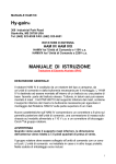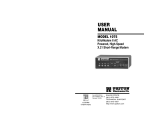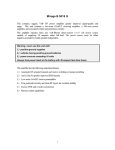
1
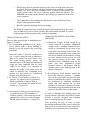
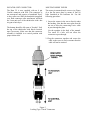
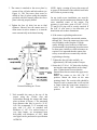
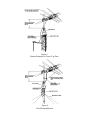
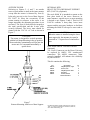
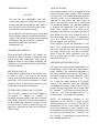
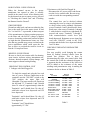
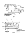
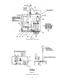
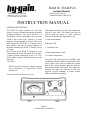
HAM IV / HAM IVX
Antenna Rotator
HAM IV has 110 VAC
Controller HAM IVX has 220
308 Industrial Park Road
Starkville, MS 39759 USA
Ph: (662) 323-9538 FAX: (662) 323-6551
INSTRUCTION MANUAL
GENERAL DESCRIPTION
The HAM IV rotator consists of a bell type
rotator, a metered control unit and the necessary
mounting hardware. The stock HAM IV is
intended for in-tower mounting on the base plate
which is part of the tower. However, in some
instances, mast mounting is desired. The Lower
Mast Support Kit, PN 51467 10, contains a lower
mast support and the necessary hardware to
facilitate mounting the HAM IV Rotator on top
of a mast.
New features in the HAM IV include an 8 pin
Cinch connector on the rear panel of the control,
a chassis ground connection on the 110 VAC
model, and a locking CinchTM connector at the
rotor unit.
CAUTION
When using the lower mast support, antenna
size is restricted to 7.5 square feet of wind
surface area
Cinch'm a Division of Labinal Components & Systems,
The rotator unit must be wired to the control unit
with an 8-wire cable. The control unit must be
placed inside the house or other protected
location. Included in the shipping box are:
A. Instruction Manual
B. Rotator Unit
C. Controller Unit
D. Mounting Hardware Pack
E. Connector Parts Pack
Due to the wide variety of towers available, each
installation will have different requirements. The
gauge of the 8-wire cable to connect the control
unit to the rotator depends upon the distance
between the rotator and control. The longer the
distance, the larger the diameter of the wire
required. Various antennas or beams require
different installation methods.
Figure 1
Control Unit - Front Panel
Specifications
Input Voltage
Optional
Motor
Brake Solenoid
Power Transformer
Optional
Meter Transformer
Optional
Meter
Meter Scale
Optional
Maximum Antenna Size:
A. Tower Mounted as per Figure 3
B. Outside Tower or mast Mounted as per Fig. 5 or 6
*Maximum Effective Moment (EM)
Operational Temperature Range
Maximum Interconnect Cable Resistance:
A. Terminals 1 and 2
B. Terminals 3,4,5,6,7, and 8
Rotation Time
Brake
Rotator Size
Maximum Antenna Mast Size
Mounting Hardware
Control Unit Size
Shipping Volume
Shipping Weight
120 VAC 50/60 Hz
220 VAC 50/60 Hz
24 VAC 2.25 Amp, capacitor start, capacitor run
24 VAC, 5.0 Amps
120 VAC/26 VAC 10% duty, thermal switch protected
220 VAC/26 VAC 10% duty, thermal switch protected
120 VAC/23 VAC continuous duty
220 VAC/23 VAC continuous duty
DC voltmeter 1000 ohms/volts, 1 MA full scale
Direct Reading: North centered, 5 degree increments
Direct Reading: South centered, 5 degree increments
15 sq. ft. (1.4 sq. m) of wind surface area
7.5 sq. ft. (0.7 sq. m) of wind surface area
2,800 ft. lb. (387 Kg. M)
-30 deg. F to 210 deg. F (-34 deg. to 99 deg. C)
.8 ohm
2.0 ohms
45-60 seconds with 60 Hz input
Positive, electrically operated wedge, 75 segments
spaced 4.8 degrees apart
8 in. (20 cm) max. diameter by 13.5 in. (34 cm) high
2 1/16” O.D. (52 mm)
Stainless steel hardware and plated steel clamp plate
8.5 in x 9.0 in. x 4.3 in. (21.6 cm x 22.8 cm x 11.0 cm)
2,280 cubic inches (37,350 ccms)
23.4 pounds (10.6 kb)
CAUTIONS
Install properly and safely
Towers, often the highest metal parts tin the vicinity, require caution during
erection and placement. Extreme care must be taken during erection so that metal
towers and beams do not contact power lines even if the beams slip or rotate,
towers fall or fracture or metal wires blow in the wind, etc.
Metal towers or other position mechanisms must be placed so that if they fracture
or blow over in high winds, they cannot contact power lines, be a hazard to
individuals, or endanger property.
When no mounted within a tower with a thrust bearing, as shown in Figures 5
and 6, the rotator must be DEBATED.
•
Metal towers must be grounded properly at the tower location before the tower
is erected. This is to minimize electrical hazard and the possibility of lightning
damage. DO NOT bury bare aluminum wires or stakes in the ground. Use
copper ground stakes. The service entrance ground should be checked. The
household convenience outlet should be the 3-prong type (grounded back to the
service entrance).
•
The Control Box is not weatherproof and must be located in the house, ham
shack or other protected location.
•
Read this manual completely before proceeding.
The HAM IV rotator has been carefully designed and manufactured to give many
years of trouble-free service when carefully and professionally installed. It consists
of the strongest and best commercially available components.
TYPES OF INSTALLATION
There are three general types of installations (see
Figures 4, 5 and 6).
l. The recommended Installation is an "Inside"
Tower Mount with a thrust bushing or
bearing to provide support and resist high
wind loads.
When the rotator is properly mounted this
way, it can be rotated to turn an antenna or
beam of 15 square feet wind surface area.
The wind loading during storms, the
rotational inertia of the beam and unbalanced
weight are more important than the dead
weight of the beam. It is important to
minimize the height of the beam above the
rotator to minimize the overturning force
induced in a high wind (see "Unbalanced
Weight" and "Wind Pressure").
2. An "outside" Tower Mount (see Figure 5) is
optional. The rotator is not well protected
but the installation is simpler. With an
"Outside" Tower Mount, the rotator must be
derated to 7.5 square feet.
3. A telescoping or other type mast (see Figure
6) can also be used. This installation is
similar to Number 2 above and requires the
optional Heavy Duty Lower Mast Support
Kit and must be derated to 7.5 square feet.
UNBALANCED WEIGHT AND WIND
PRESSURE
I. Unbalanced Weight: Weight should be as
closely balanced as possible. Unbalanced
weight creates a bending moment of force
which is concentrated on the mast at the
point where it is clamped to the rotator. This
moment tends to strain the mast at that point
and also to bind the ball bearings by creating
excessive downward pressure on one side
and upward pressure on the other. Such
unbalance places additional stress on the
motor gear train. Unbalanced weight
becomes critical as the distance from the
antenna boom to the clamping point at the
rotator is increased.
2. Wind Pressure: Wind pressure against the
boom and elements produces a bending
force on the mast which can cause the same
stresses as unbalanced weight. To strengthen
the installation to withstand unbalanced
weight and wind pressure the tip mast
should be as short and as strong as possible.
In multiple arrays the antenna with the most
wind area should be closest to the rotator.
In order to distribute the bending stress and
prevent fracture of the mast, the HAM IV rotator
includes a specially designed steel clamping
plate to clamp the mast to the rotator;
After procuring the type of tower or other
positioning mechanism of the owner's choice, the
next step is to wire the rotator to the control box
and check out its operation prior to installation.
WIRING AND CHECK-OUT
A. Decide the wire gauge (size) required and
procure the number of feet of the proper cable
(see Table 1).
Maximum
Length
Gauge for
Terminals 1 & 2
Gauge for
Terminals 3-8
125' (38 m)
200' (61 m)
300' (91 m)
#18 (1.19 mm)
#16 (1.42 mm)
#14 (1.75 mm)
Table 1
#20 (.97 mm)
#18 (1.19 mm)
#16 (1.42 mm)
D. With the rotator sitting in the upright position
and connected to the control unit by the 8wire cable, plug the control unit power cord
into a receptacle.
E. Turn the power switch on. The meter should
be illuminated.
F. Depress the "Brake Release" (center) lever,
then release it. An audible click should be
heard in the rotator. This is the solenoid
operating the brake wedge.
Figure 2
Control Cable Connector Attachments
G. Depress the "Brake Release" (center) lever,
NOTE: The specifications call for heavier
hold it, and simultaneously depress the
gauge wire in two locations. Leads #1 and #2
CCW direction switch (left). The rotator
must be heavier gauge and less total lead
should turn CCW (looking from the top).
resistance.
This is S-E-NW-S. Release the CCW
direction switch; the rotator will coast down
B. Assemble the rotor cable as shown in Figure
and stop. Now release the brake switch. The
1.
rotator is now locked into position.
CAUTION
Shorts between terminals or grounded leads may
damage the rotator.
:
C. Temporarily attach the 4 1/4"-20 x 1 1/4"
screws (Item 147) to the bottom of the rotor
unit.
H. Repeat the previous step for CW direction by
depressing the brake switch first, then the
CW direction switch (right).
CAUTION
It is best to release the direction switch just
prior to the end of rotation (extreme CW or
CCW position) in order not to cause undue
stress on the stop arm and/or the gears.
ROTATOR UNIT CONNECTOR
MOUTING INSIDE TOWER
The Ham IV is now supplied with an 8 pin
Cinch® connector with lock. This connector is
not waterproof and requires a heatshrink "boot"
to keep water out. Slide the heatshrink (supplied)
over both connectors after attachment, and heat
the "rotor unit end" of the shrink-tube with a hot
air-gun or hair-dryer.
The rotator is mounted inside a tower (see Figure
4) to the flat tower plate by means of four (4)
bolts furnished in the hardware kit. Use the
following procedure:
The bottom should be left open to "breathe". Seal
the top of the shrink-tube with black electrical
tape if necessary. Make sure that this connector
assembly is installed in a vertical position with
proper strain relief.
1. Locate the rotator in the tower directly under
the bushing. Note that the tower plate must be
cut out to allow the connecting 8-wire cable
to pass through the plate.
Use the template in the back of the manual.
Too small of a hole will not allow the
connector to pass through.
2. Plug the connectors together and secure the
cable to the tower in such a manner that the
cable will not be strained.
Figure 3
Locking-Type "Cinch" Connectors
3. The rotator is attached to the tower plate by
means of four (4) bolts and lockwashers (see
Figure 4). The flat tower plate must be
drilled in four (4) places using the template
provided with this manual unless the tower
plate is already properly drilled.
4. Tighten the four (4) bolts, but not to final
tightness. Observe how the rotator turns. It
must rotate in such a manner as to turn the
mast concentrically in the thrust bearing.
NOTE: Apply a coating of heavy-duty motor oil
or grease to the threads of the stainless steel bolts
and U-bolts to prevent seizing.
On any inside tower installation, care must be
exercised to get the antenna mast shimmed to the
exact rotational center of the rotator. The
geometry is such that a mast of 2.062" (21/16"
[52 mm]) O.D. pipe will be exactly centered. If
the O.D. of your mast is less than this, you
should shim out to these dimensions.
6. If the rotator, top bushing and mast are
aligned, there should be unrestricted rotation
through 360°. If not, the rotator may have to be
moved slightly on the flat plate. If a high
quality bearing is used in the top of the tower
(recommended), the shimming procedure must
be done more carefully as closer tolerances are
required. It is important that the rotator does
not try to turn the mast eccentrically with the
top bushing or bearing.
7. Tighten the four (4) bolts carefully - to
approximately 100 inch-pounds of torque.
Figure 4
Rotator Mounting in a Tower
5. Trial assemble the mast to the top of the
rotator using the U-bolts, nuts and
lockwashers through the rotator and clamp
plate as shown in Figure 4. The maximum
mast diameter that may be used is 21/16"
O.D. We recommend 1 1/2" nominal steel
pipe with 1.9" O.D. in standard wall
thickness of .145". For stacked arrays or
very large beams, we recommend extra
heavy-duty wall thickness of .200". Both
steel pipes can be purchased to specification
ASTM120.
8. Insert the 1/4"-20 x 1 1/4" bolt with a locking
nut into the center tapped hole in the clamp
plate. Tighten down to assure that the
antenna mast does not turn in the upper mast
support.
Return the rotator to the full CW "S"
position. Mount the beam on the mast
pointing South. The coaxial cable should be
looped in such a manner that it will not foul
or tangle when the beam turns around in a
circle to the full 360° counterclockwise
position.
Figure 5
Rotator Mounted on Tower Top Plate
Figure 6
Pole Mounted Rotator
OUTSIDE TOWER
Referring to Figures 5, 6, and 7, an outside
tower or pole mount is made in the same manner
except that the rotator is fastened by four (4)
bolts only (not six) to the Lower Mast Support,
PN 51467 10. Since the eccentricity of the
rotator turning in reference to the tower is no
longer important, the shimming procedure is not
necessary. The four (4) bolts must be torqued to
the same specification and the 8-wire cable
securely fastened. The lower mast should be
pinned with the 5/16"-18 x 4" bolt as shown in
Figure 7.
OPTIONAL KITS:
HEAVY-DUTY LOWER MAST SUPPORT
KIT (51467-10) (Optional)
The stock HAM W is intended to mount on the
base plate inside of the tower. However, in
some instances, outside tower or mast mounting
is desired as per Figures 5 and 6. This kit, P/N
5146710 contains a heavy-duty lower mast
support and the necessary hardware to facilitate
mounting the HAM IV on top of a tower stub or
mast.
CAUTION
When the rotator is installed using the lower
mast support kit, the antenna size must be
restricted to 7.5 square feet of wind surface
area.
CAUTION
The rotator is designed for vertical operation
with the bell shaped housing in the up position.
Water and other contamination will get into the
motor unit if it’s mounted horizontally or
upside down.
WEATHER-PROOF CONNECTOR KIT
(Optional)
The Cinch' Connectors on the Rotor Unit may
be replaced by AMP© CPC weatherproof
connectors. The AMP© connectors, when
properly installed, will enhance the reliability
of your HAM IV.
This kit contains the following
PN
650179
650291
650180
650181
650293
Figure 7
Rotator Mounting with Lower Mast Support
Description
Amp Receptacle, 9 pin
Contact, Pin
Amp Receptacle shell
Amp plug
Contact, Socket
Instruction Sheet
CinchTM a Division of Labinal Components & Systems, Inc.
AMP* is a registered trademark of AMP-Barrel, AMP Inc.,
939 E. Park Dr. Harrisburg, PA
8
Qt
1
8
2
1
8
1
PRELIMINARY CHECK AND
CALIBRATION
IMPORTANT
THERMAL PROTECTION: If the rotator
fails to turn after 4 or 5 minutes of
continuous operation, the thermal switch has
come into play. This protective device in the
transformer automatically shuts off power if
the rotator is used continuously for too long.
It will automatically reset after 10 minutes.
l. Turn the Control Unit Power "ON" with the
upper right "ON-OFF" switch. The meter
should be illuminated and the needle should
be to the right.
2.
3.
Depress the brake lever (center) and hold.
Depress the CCW lever (left) and operate
the rotator to its full CCW position.
With the rotator in its full CCW position, if
the meter is not at its full left position,
carefully adjust the zero (CCW South)
position with the screw directly under the
meter to exactly South.
4. Meter Calibration Procedure: Operate the
rotator to its full clockwise position. Adjust
the calibration potentiometer until the meter
indicates full scale to the right. The meter is
now calibrated. Do not adjust the calibration
potentiometer when the rotator is in any
position other than full clockwise.
When the control unit is turned "OFF", the meter
needle will fall to the left "S" position and return
to indicate the rotator position as soon as the
control unit is turned "ON' again. It will not
damage the unit to leave it turned "ON" for
extended periods.
NORMAL OPERATION
To operate the rotator, it is necessary to
understand the HAM IV Brake Release Lever
and its function. The brake lever (middle lever)
on the Control Unit operates a brake wedge
mechanism in the rotator which locks the rotator
into position mechanically. The rotator cannot
turn unless the wedge is retracted by depressing
the middle lever. The normal operation is as
follows:
l. Retract the brake wedge by holding down the
"Brake Release", middle lever.
2. Turn the rotator to the compass location by
pushing down and releasing either the left
hand or the right hand lever.
Allow a few seconds for the rotator to coast
down. Then re-engage the brake wedge by
releasing the "Brake Release" (middle) lever.
OPERATING PRACTICE
The rotator has several mechanisms to protect it
from misuse, but the following precautions are
advisable.
1. If you have a very large beam, the rotator can
be "nudged" to exactly the desired position
by alternately working the left and right
control, allowing it to coast down before the
brake wedge is allowed to engage.
2.
It is advisable not to run it full speed into the
end of rotation.
3. Upon completion of turning, always allow the
rotator to coast down by keeping your finger
on the "Brake Release" after you have
released the rotation lever. This procedure
will allow the rotator to stop before you reengage the brake wedge. Observing this
sequence prevents the rotator from stopping
suddenly thus preventing undue stress on the
rotator, beam, and tower.
The motor has an internal brake which controls
the coast down time and deceleration. The
internal motor brake is usually strong enough to
prevent pinwheeling during operation even in
high winds. If the rotator is being operated in a
very high wind, observe the operation of the
needle. A little practice will acquaint the owner
on how to operate the rotator smoothly.
GROUNDING
The tower, or other metal support device, must be
grounded to an earth ground at its location. Use
heavy copper cable looped so that if the tower
comes down for any reason, there will be adequate
slack to prevent the ground wire from breaking.
Use one or more 8 foot copperjacketed steel stakes
driven into the moist earth and fasten the wire
securely at the stake and at the tower.
As mentioned in the "Cautions" portion, the steel
chassis of the control box should be either
grounded to a metal cold water pipe in the house
or back to the electric service entrance box where
the power comes into the house. This normally is
accomplished with the wire of the 3-prong plug
which then depends on the wall outlet being adequately grounded back to the service entrance as
to the utility ground. If there is any doubt, have
this checked by a licensed electrician.
SOUTH-CENTER METER SCALE
CONVERSION
The stock HAM IV Control Unit is shipped with
the meter scale installed for "North" center
operation; ends of rotation are at the "South"
position. Some geographic locations and/or
popular working areas may favor having the
meter "South" center; ends of rotation are at the
"North" position. We have provided the HAM IV
with an interchangeable meter scale.
5. Carefully remove the hex nuts on the meter
studs to free the printed circuit board. Slip the
P.C. Board off the studs and pull it down
under the chassis.
CAUTION
It is good practice to use a short test lead or
jumper wire to short the meter studs when it
is not in the circuit.
6. Loosen the meter retaining clips and remove
the meter from the chassis.
7. Insert a small knife blade between the clear
meter cover and black housing at either
corner of the top edge and gently pry the
cover loose from that corner. Repeat for the
other corner. The meter cover should pop
off.
8. Carefully slip a knife blade under each corner
of the lower edge of the white meter scale
and twist slightly until the scale clears the
two small indexing pins. Remove the scale,
turn it over and reinstall it. Make sure the
scale fits over the indexing pins and that it is
flush and tight against the black housing.
This will assure free movement of the
indicator needle.
9. Reinstall the meter (remove the temporary
jumper), the P.C. Board and lamp hardware.
Check for pinched, shorted end, or
overstressed wires.
10. Reinstall the top and bottom
We recommend the following
1.
2.
Disconnect the power
11. Reconnect the 8-wire control cable in the
exact sequence as they were removed.
Remove the 8-wire control cable, carefully
labeling each wire with its corresponding
terminal number. This operation may be
omitted if the control box can be worked on
easily without removing the leads.
If your beam was installed originally using the
HAM IV with a "North" center scale, the
antenna mast must be loosened and repositioned.
In order for the meter to indicate properly, the
front of your beam must point "North" when the
rotator is at the ends of rotation.
3. Remove the top and bottom covers.
4.
Slip the lamp and holder off the lamp holder
bracket. Loosen the hex nut on the
transformer that is holding the lamp holder
bracket and swing the bracket clear of the
wires leading to the printed circuit board.
Recalibrate the meter.
NOTE: In the past the South Centered meter
scale was on the reverse side of the factory
installed North Centered scale. The unit is now
provided with a separate South Centered scale.
This will help to avoid damage to the face of the
meter scale during removal of the North
Centered scale.
TROUBLESHOOTING
CAUTION
This unit has been thoroughly tested and
cycled before shipment. Follow the connector
wiring carefully between Rotator and Control
Box. Incorrect wiring will burn out the rotator
potentiometer and void the warranty.
Be sure Rotator and Control Units are compatible.
Do not intermix models with different operating
voltages. This results in sluggish or non-operating
performance, burned out motors, overheated
transformers and burned out rotator
potentiometer, etc..
GENERAL DESCRIPTION
Most operational difficulties with rotators are
traceable to broken, shorted or grounded wires
usually at the rotor connections. Time spent in
cutting the leads to exact lengths, soldering, and
clamping to prevent strain on the control cable,
will pay dividends.
MECHANICAL PLAY
Frequently the slight motion of the antenna array
in gusts of wind is due more to the natural
flexing of the elements and mast than it is due to
actual play in the rotator mechanism. A slight
amount of "play" is built into the rotator to avoid
binding due to environmental changes.
ANTENNA ROTATES IN HEAVY WIND
This is usually a matter of the mast slipping in
the support. If "slipping" or "turning" is
suspected, return the rotator to the end of rotation
and visually check to be sure that the antenna is
in the original stop location as installed. Check
the nuts on the U-bolts to insure that they are
tight. Also, check that the center bolt in the mast
clamp is tight.
LACK OF POWER
If the antenna rotation is slow or sluggish or hard
to start, check for proper voltages. If the voltages
are correct, the 130-156 mfd motor start capacitor
could be at fault. It is recommended that a new
capacitor be tried before any other action is
taken. If the electrical circuit is okay, then check
for mechanical binding. Pay particular attention
to bearings and alignment of the shaft on an
inside tower mount. On any inside tower
installation, care must be exercised to get the top
mast shimmed to the exact rotational center of
the rotator upper mast support. If temperatures
are at -30°F (-34°C) or lower, operation will be
slow or sluggish. This is normal!
If the capacitor is good, the temperature is well
above -30° F, and there is no mechanical binding
above the rotor, the rotor may not be receiving
the proper voltage levels to achieve maximum
torque. Check the cable resistances, and wire
sizes. For cable runs over 300', move the motor
capacitor to the tower.
IMPROPER METER INDICATION
The brake and motor operate independently of
the indicating system. If the pilot light burns at
proper brilliancy, the instrument transformer is
okay and the output is not shorted. Check the 1/8
amp meter circuit fuse with the ohmmeter. Check
for about 13 VDC across Terminals No. 3 and
No. 7 with the switch operated. If the proper
voltage is not obtained, check the individual
components in the meter circuit. If the 13 VDC is
present, check for 500 ohms across rotator leads
No. 3 and No. 7. If 500 ohms is present from No.
3 and No. 7, see if the readings from No. 3 to
ground and No. 7 to ground total 500 ohms.
NOTE: An intermittent condition in any
component in the rectifier or meter circuits
within the control box, as well as in the cable or
potentiometer circuit in the rotator itself can
cause meter fluctuation or error. Possible cause
of such trouble may be localized by placing a test
DC meter across Terminals No. 1 and No. 3 or
No. 1 and No. 7 comparing the action of the test
meter with the panel meter.
NO ROTATION - INDICATION OK
Either the thermal cut-out in the power
transformer has opened or there is actually
trouble in the motor circuit. After allowing time
for the thermal cut-out to restore service, proceed
to "Checking the Control Unit" and "Checking
the Rotator from the Ground".
2. Resistances with Unit Not Plugged In.
Disconnect the AC power source and disconnect the 8-wire control cable. Be sure to tag
each wire with the corresponding terminal
number.
The control box can be checked without
removing the cover by using a volt-ohmmeter
to check values across terminals. Resistance
across Terminals 1 and 2 should read 4 ohms.
Read same value across Terminals 1 through
5 with clockwise switch lever (right hand) depressed and across Terminals 1 through 6
with counterclockwise switch lever (left
hand) depressed. Resistance across input line
cord with "ON-OFF" switch in the "ON"
position and the brake lever depressed should
read 3.8 ohms.
GROUND WIRES
Ground on cable leads can burn out either the line
fuse or the small fuse in the meter circuit. If lead
No. 3 or lead No. 7 is grounded, it shorts out part
of the potentiometer so that as rotation progresses
to the other end, the full DC voltage is applied
across a decreasing portion until current becomes
so high that the potentiometer burns out. Note
also that any grounds may put an overload on the
power transformer which could cause the line
fuse to blow or overload the rectifier circuit so
that the 1/8 amp fuse blows.
CHECKING THE ROTATOR FROM THE
GROUND
You may possibly avoid bringing the rotator
down by making electrical checks from the
control box position. This is done by
disconnecting the eight wire control cable from
the control unit. From the schematic diagram, it
is apparent that the resistance of the lead wires
will be added to the resistance of the motor
windings and potentiometer strip in making the
resistance checks as shown in Table 2.
HELPFUL SUGGESTIONS
Be sure to check your rotator cable for shorting,
open circuits, incorrect wiring, intermittent connections, shorted terminals, rodent damage, and
mast support or thrust bearing binding.
CHECKING THE CONTROL UNIT
1. Voltages with Unit Plugged In.
To check the control unit, plug the line cord
into AC power. With no connections to the
terminals, turn the "ON-OFF" switch to the
"ON' position, the meter light will
illuminate. The meter needle will remain on
the left hand "S". Terminals 1 and 2 should
show 30 volts AC (approximately) when the
Read
To Check
Brake
Solenoid
1/2 Motor Winding
1/2 Motor Winding
1/2 Motor + Switch
1/2 Motor + Switch
Entire Motor
Right Limit Switch
Left Limit Switch
Entire Pot
Pot Arm to + End
Pot Arm to - End
Terminals 1 and 5 should show 30 volts AC
with brake release lever depressed and CW
lever depressed.
Terminals 1 and 6 should show 30 volts AC
with brake release lever depressed and CW
lever depressed.
Between
Resistance
.75 ohms + leads
1-2
2.5 ohms + leads
2.5 ohms + leads
2.5 ohms + leads
2.5 ohms + leads
5 ohms + leads
0 ohms + leads
0 ohms + leads
500 ohms
0 to 500 ohms
0 to 500 ohms
1-8
1-4
1-6
1-5
8-4
8-5
4-6
3-7
3-1
7-1
Table 2
Terminals 3 and 7 should show
approximately 13 VDC.
12
Terminals
ADDITIONAL CHECKLIST
l. Check continuity of control wires for loose
connections caused by wind.
2. Tape down control cable securely all the way
to rotator.
3.
Check motor winding through control cable
as outlined in Table 2.
4. Check cable between leads. Static lightning
charges or direct hits will cause carbon arcs
in control cable at numerous spots along the
cable that cannot be seen. This resistive path
will break down with voltage applied to
rotator. (Replace cable.)
5.
Check both control and rotator connectors
for shorts.
6. Rotation in one direction usually indicates a
loose or broken cable wire, bad relay, and
bad sensing transistors in some units.
7.
Be sure cable is of proper size for length
used. Refer to Table 1.
8.
Substitute a 3 foot piece of new rotator cable
to bench test unit. Proper operation will
indicate a defective rotator cable on the mast
or tower, or a cable not large enough to
create proper turning torque.
9. Low line voltage and cold weather will slow
rotation. Using an extra long or small wire
extension cord can lower line voltage.
PARTS LIST
HAM IVControl Unit Replacement
ITEM
NO.
1
2
3
11
12
13
14
15
16
17
18
20
21
22
23
24
25
26
27
28
29
30
31
32
33
34
35
36
37
38
39
40
41
42
43
44
45
46
PART
NO.
5156502
5156500
5139000
1034403
5089501
710053
5138600
5141100
5141200
5152700
520057
640076
5088400
450403
506665
560068
1073501
1073301
5020200
5017700
5151500
5086100
450431
5079800
5147702
5175200
723406
1056300
710054
5156100
5089103
506325
567110
567120
556960
550029
710083
567125
DESCRIPTION QTY
Control Unit, 220VAC, complete ............................................................... 1
Control Unit, 120VAC, complete ............................................................... 1
Printed Circuit Board .............................................................................. 1
Fuse, 3 Amp, F-2 (110V version) ............................................................1
Bulb, Meter, #1819 ..................................................................................1
Fuse, 1 Amp, Slo-Blo, F-2 (220V version) .............................................. 1
Switch, Snap, S-3, S-4, S-5 .....................................................................1
Cover, Top ...............................................................................................1
Cover, Bottom ..........................................................................................4
Pads, Skid.................................................................................................9
Screw, #6-32 x 3/8", Pan Head ................................................................8
Socket, Cinch, S-308-AB ........................................................................ 1
Lever, Switch, for S-3, S-4 & S-5............................................................1
Relief, Strain, Heyco 3772 (220V version) .............................................. 2
Screw, #6-32 x 1/4", round head..............................................................2
Washer, Back-up (220V version).............................................................1
Transformer, Power (220V version) ....................................................... 1
Transformer, Power (120V version) ........................................................1
Transformer, Meter (220V version).........................................................1
Transformer, Meter (120V version) .........................................................1
Capacitor, Motor Start............................................................................. 1
Cord, Line, 3-wire (120V version)...........................................................1
Relief, Strain, Heyco 1217 (120V version) .............................................. 1
Cord, Line, 3-wire (220 VAC; European Plug) ........................................ 1
Meter........................................................................................................1
Switch, On/Off S-1 ..................................................................................1
Potentiometer ........................................................................................... l
Holder, Fuse, for F-2; (120V version) .....................................................1
Holder, Fuse, for F-2; (220V version) .....................................................1
Plate, Face ................................................................................................ l
Chassis .....................................................................................................1
Bolt, Hex Head, 1/4"-20 x 3/4" ....................................................................1
Lockwasher, Int. 1/4" .................................................................................. 2
Flatwasher, 1/4" ...............................................:...........................................2
Nut, Hex, 1/4"-20.........................................................................................1
Nut, Wing, 1/4"-20.......................................................................................1
Holder, Bulb.................................................................................................1
Lockwasher, #10 Internal............................................................................ 4
Hy-Gain reserves the right to change prices at its option. Current prices may be obtained by calling or
writing the factory.
Figure 9
Wiring Schematic
Figure 10
Control Unit - Front Panel
Figure 11
Control Unit - Top View
Figure 12
Control Unit - Back View
16
HAM IV Rotator Replacement Parts
ITEM
NO.
101
102
103
104
105
112
124
125
126
140
141
142
143
*
*
*
*
*
*
170
171
172
173
174
175
176
PART
NO.
878712
5030400
5136502
5033501
5011300
5136101
5137600
5023100
5009900
179894
510680
520057
5105700
5011500
5038200
5050200
110820035
554099
561177
5030400
450590
610215
640091
640092
411830
640077
DESCRIPTION QTY
Rotator (complete with hardware) ..............................................................1
Support, Upper Mast (bell casting) .............................................................1
Brake Housing (lower casting) ....................................................................1
Bearings, Ball (49 per retainer)..................................................................98
Retainer, Bearing (one per race) .................................................................2
Gear, Steel Drive..........................................................................................1
Motor and Pinion .........................................................................................1
Potentiometer ...............................................................................................1
Solenoid .......................................................................................................1
Mounting Plate.............................................................................................1
Screw, #6 x 3/8", torque............................................................................. 2
Screw, #6-32 x 3/8", Pan Head ....................................................................2
Screw, #12-24 x 3/4"................................................................................... 4
Plate, Mast Clamp .............:..........................................................................1
U-Bolt, 1/4"-20, 2 1/4" x 3 7/8"...................................................................3
Flatwasher, 5/16" .........................................................................................4
Bolt, 1/4"-20 x 1 1/4", Hex Head.................................................................5
Nut, 1/4"-20, Hex.........................................................................................5
Lockwasher, Split, 1/4", SS ........................................................................ 9
Support, Upper Mast....................................................................................1
Strain Relief .................................................................................................1
Cable, 8 conductor ............................................................................... 2.0 ft.
Plug, 8 Pin Cinch" w/lock ......................................................................... 1
Parts Pack, Connector (878713)........................................................................ 1
Socket, 8 pin Cinch w/ lock ......................................................................1
1 1/2 inch shrink tube ............................................................................ 4 in.
Plug, 8 Pin Cinch........................................................................................1
*Contained in Mounting Hardware Kit PN
NOTE: A complete parts listing is contained in the service manual, PN 801935-6
CinchTM a Division of Labinal Component% & Systems,
Figure 13
Inside View of HAM IV Rotator
HOLES TO BE 17/64 CLEARANCE DRILL
TOWER DRILLING TEMPLATE
This information is believed correct, but no warranty is given or implied and no liability is
assumed by Hy-Gain as to its accuracy or completeness. Changes may be made from time to
time so the user should verify all factors that may be critical. This information is not to be
construed as to authorizing or advising use of any patented invention.
LIMITED WARRANTY
Hy-Gain Warrants to the original owner of this product, if manufactured by Hy-Gain
and purchased from an authorized dealer or directly from Hy-Gain to be free from
defects in material and workmanship for a period of 12 months for rotator products and
24 months for antenna products from date of purchase provided the following terms of
this warranty are satisfied.
1. The purchaser must retain the dated proof-of-purchase (bill of sale, canceled check,
credit card or money order receipt, etc.) describing the product to establish the
validity of the warranty claim and submit the original or machine reproduction of
such proof of-purchase to Hy-Gain at the time of warranty service. Hy-Gain shall
have the discretion to deny warranty without dated proof-of-purchase. Any evidence
of alteration, erasure, or forgery shall be cause to void any and all warranty terms
immediately.
2. Hy-Gain agrees to repair or replace at Hy-Gain’s option without charge to the
original owner any defective product under warranty, provided the product is
returned postage prepaid to Hy-Gain with a personal check, cashiers check, or
money order for $8.00 covering postage and handling.
3. Under no circumstances is Hy-Gain liable for consequential damages to
person or property by the use of any Hy-Gain products.
4. Out-of-warranty Service: Hy-Gain will repair any out-of-warranty product
provided the unit is shipped prepaid. All repaired units will be shipped COD to
the owner. Repair charges will be added to the COD fee unless other
arrangements are made.
5. This warranty is given in lieu of any other warranty expressed or implied.
6. Hy-Gain reserves the right to make changes or improvements in design or
manufacture without incurring any obligation to install such changes upon any of
the products previously manufactured.
7. All Hy-Gain products to be serviced in-warranty or out-of-warranty should be
addressed to hy-gain,
308 Industrial Park Road,
Mississippi 39759, USA and must be accompanied by a letter describing
the problem in detail along with a copy of your dated proof-of-purchase.
8. This warranty gives you specific rights, and you may also have other rights which
vary from state to state.