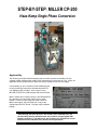
1
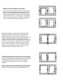
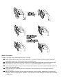
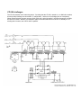
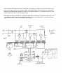
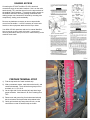
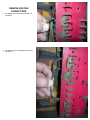
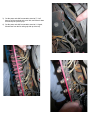
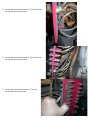
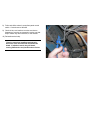
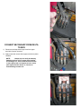
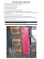
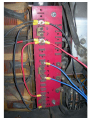
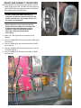
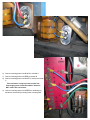
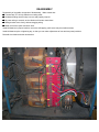
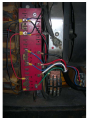
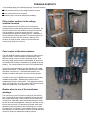
STEP-BY-STEP: MILLER CP-200
Haas-Kamp Single Phase Conversion
Applicability
The following procedure identifies step-by-step conversion process for the Miller CP-200
constant-voltage welding power supply series manufactured in the vicinity of 1973. It MAY be
applicable to other years, however, there are several variations of the CP-200 supply.
It is necessary for you to research YOUR model and year
to verify that wiring connections indicated here MATCH
your welding supply’s vintage. On the front of every
MILLER CP-200 is the model number AND serial number.
Miller’s website has a lookup function in the RESOURCES
tab, attempt to do a document search for your serial
number. If none is found, send your serial number to
Miller’s site support, they will Email you a copy of the
original manual in PDF format. They are truely wonderful
people!
Read through the entire process, and compare each indicated step, and
corresponding drawing indication with your welder’s wiring diagram AND
internal connections. If at ANY point, you find that your connections are not
identical to those indicated here, do NOT use this procedure.
About the Haas-Kamp conversion
The Haas-Kamp method utilizes a simple process for fully
powering a 3-phase welding transformer with single-phase
power. In a properly powered 3-phase transformer, the
incoming power’s 3-phase sequence occurs at 120 degree
intervals (360 divided by 3 = 120 degrees). The operating
result in a 3-phase transformer, is magnetic circulation that
occurs in a figure-8 pattern between coils A, B, and C.
Many people attempt to convert surpus 3-phase welders to
single-phase power by connecting some or all coils of the
welding transformer to be powered by a single-phase line.
While this frequently results in a certain amount of operational
capacity, it is usually very limited- either output current or
voltage, and poor arc stability. The reason for poor and limited
performance, is because the 3-phase transformer is designed
in such a way that magnetic circulation occurs in a figure-8
through each coil in sequence, but when using the ‘common
methods’, the sequence doesn’t exist, so the transformer’s
magnetic strength is crippled by eddy currents.
The Haas-Kamp conversion method utilizes a wiring technique
that does precisely that, by connecting the two outer coils of the
transformer 180 degrees out-of-phase, and driving the MIDDLE
coil 90 degrees out-of-phase, the magnetic flow sequence
circulates through the transformer core as was originally
designed.
Once the sequence has been established, the cores are able to
generate output, and as a result, the welding supply’s output is
same as if it were running on genuine three-phase power.
Basic Procedure:
The basic procedure for any Haas-Kamp conversion, is simple:
z Isolate the individual coils of the main power transformer. Second is to isolate any other segments (additional
single-phase loads like fan, control transformers, and other devices).
z Configure the main transformer so that windings can be fed 240v single-phase power, and next is to wire the two
outer primaries (A and C) to incoming 240v, but wire the C phase BACKWARDS in relation to A phase.
z Connect the B phase (center coil) to incoming mains through capacitors to provide 90 degrees of phase shift at the
welder’s Full Load Amps rating.
z Configure and connect all ancillary devices (cooling fans, control transformers, etc) to the single-phase line
connection points.
z Make any alterations necessary to make proper welder control, and if necessary, adaptations to put the welding
transformer output in proper realm for operation. (in the CP-200, this means changing secondary side from Delta to
Y configuration).
CP-200 challenges
The CP-200 presents some interesting twists... first being that the CP-200 I started on, is a 480/240v machine,
but the primary windings are connected in Y configuration... there’s six coil windings (two on each phase).
When voltage-selection jumpers are set to 240v, each coil is wired in parallel... and when jumpers are in 480v,
all coils are in series. With the y-centerpoint in place, that means that each LEG of the Y is actually a 277v
winding when in series, and 138.5v when in parallel.
This conversion entails disconnecting the centerpoint, and treating each phase like a 240v load, which means
we’re only driving the (277v) coil to a portion (240v) of it’s design voltage. We’re down by 14%. That means,
that when our indicated output voltage (on machine’s front panel) indicates 17v, we should only see 14.7, and
at 28v, we’ll only see 24.2v. This is a pretty big drop.
Fortunately, the CP-200’s OUTPUT is configured as delta, and converting it to Y couldn’t be much easier... the
commensurate boost in output voltage brings it right back to where output SHOULD be, and testing indicates
output current and duty cycle are not hindered by the change.
GAINING ACCESS
Converting the CP-200 The Miller CP-200’s electrical
connections occur in two basic locations- first is on the main
terminal strip (TE1), and the second is on the top terminals of
the welding output contactor. This requires gaining access to
the welder’s internals, removing existing connections and
making proper new connections, followed by mounting new
componentry, testing, and reassembly.
Remove any hardware necessary to remove top and side
covers from the welder. It will be necessary to remove wire
feeders or other equipment attached to the top or sides.
Your Miller CP-200 operations and service manual identifies
how to remove covers to reach this panel. I recommend
removing both sides, and top cover, as it makes working on the
machine much easier.
PREPARE TERMINAL STRIP
1) Find the top terminal of main terminal strip.
2) With a permanent marker, mark this terminal as #1, and
continue downward. There will be three groups of four
terminals, so 1-4, 5-8, 9-12.
3) On the right side of main terminal strip are three large
power terminals. Label these A, B, and C starting from
TOP.
4) Remove nut and ground lug from bottom terminal strip
bolt, then bottom and top terminal strip retainer bolts.
5) Gently pull terminal strip away about an inch, so that
connections on rear of terminal strip are visible.
REMOVE EXISTING
CONNECTIONS:
1) Cut jumper wire connecting terminal 1 to
terminal 5.
2) Cut jumper wire, connecting terminal 5 to
terminal 9.
3) Cut fan power wire #40 connected to terminal 7. You’ll
have to pull the terminal strip out a little, and follow it down
from the zip-tie’d point up top.
4) Cut fan power wire #20 connected to terminal 11. Again,
follow these from the fan wiring zip-tied up at the top.
5) Cut wire #8 connected at terminal 12. This is done from
the right side of the terminal strip.
6) Cut wire #9 connected at terminal 8. This is done from
the right side of the terminal strip.
7) Cut wire #10 connected at terminal 4. This is on
the left side of the terminal strip.
8) Follow wire #8 to where it meets front panel control
switch. Cut and remove Wire #8
9) Check all wire cut locations to make sure that no
fragments of cut wire are exposed in such a way that
they’ll contact any other terminals, or the chassis.
10) Reinstall terminal strip.
Exercise care when installing terminal stripwires from coils are solid-core and tend to be
brittle. If pulled too much, they will break,
causing malfunction and possible short circuits.
CONVERT SECONDARY FROM DELTA
TO WYE
1) Disconnect and tape three large wires from upper
terminals of power contactor.
2) Apply jumper bar across three upper terminals of power
contactor
NOTE:
Jumper bar can easily be made by
flattening a piece of 3/4" copper pipe, bending
and drilling to fit. Some contactor terminals are
in same plane, this one happens to have center
pole higher than the others, so I had to do
some bending to make it fit.
MAKE NEW POWER CONNECTIONS:
1) Using 3/8" nutdriver, loosen all terminal strip nuts, and remove all jumpers
2) Remove nuts from terminals 1, 4, 5, 8, 9, and 12.
3) Install blue 10awg wire on terminal #5
4) Install blue 10awg wire on terminal #8
5) Install jumper from terminal 6 to 7.
6) Install red 10awg wire from terminal #9 to terminal #4.
7) Install another red 10awg wire 24" long on terminal #4, lay it down near capacitors.
8) Apply red tape to wire #9, Trim and apply ring lug, and connect to terminal #4 along with fan power wire
#20 and install nut.
9) Install black 10awg wire from terminal #12 to terminal #1.
10) install another black 10awg wire 24" long on terminal 2, lay it down near capacitors
11) Apply ring lug to wire #10, and connect to terminal 1 along with fan power wire #40 and install nut.
12) Install jumper from terminal 10 to 11.
13) Verify all connections, double-check torque on all terminal strips.
Terminal strips are brass, do not overtighten, as they will break.
MOUNT AND CONNECT CAPACITORS
Mounting capacitors is entirely dependant upon the size and
shape of capacitors found. The Miller CP-200 requires oilfilled ‘MOTOR RUN’ type capacitors of 60 microfarad (uF),
with voltage rating of at least 370vac.
Do NOT use MOTOR START capacitors, or
capacitors not rated for continuous duty AC, and
do NOT go below 370v. Any voltage above 370 is
fine, 450v is recommended.
Mount capacitors in any convenient and safe
location within the cabinet. You will likely need
to fabricate appropriate brackets to secure
capacitors. Keep in mind that the welder is
inherently a dirty and vibration-prone
environment.
1) Solder 15k 5 watt resistor across terminals of each
capacitor.
2) Connect 10AWG RED wire from terminal #4 to ONE lug of
one capacitor.
3) Connect 10AWG BLUE wire from terminal #8 to OTHER
lug of capacitor.
4) Connect 10AWG BLACK wire from terminal #1 to one lug
of OTHER capacitor.
5) Connect 10AWG BLUE wire from terminal #5 to OTHER
lug of capacitor.
6) Connect incoming power cord BLACK to terminal A
7) Connect incoming power cord RED to terminal B
8) Connect incoming power cord WHITE (if exists) to terminal
C
This connection is only to prevent a white wire
from hanging loose inside the cabinet. Neutral is
NOT used in this conversion.
9) Connect incoming power cord GREEN to remaining lug
and bolt to terminal strip mounting lower mounting stud.
REASSEMBLY
Reassembly of the welder is opposite of disassembly. Make certain that:
z Terminal strip TE1 is fully seated on mounting studs
z Hardware holding terminal strip is secure and properly torqued
z All power wiring is secured, as fan vibration will loosen connections.
z Sliding brushes move freely, without snagging wiring.
z Metal covers won’t pinch and short wires.
Install all fasteners in proper locations- some are self-tapping, while some may be machine-screws.
Install all fasteners prior to tightening any, so that you can make adjustments to front and rear panel positions.
Reinstall wire feeder and other accessories.
CORRECT ALL LABELS
It is very important that the unit be appropriately re-labeled to indicate it’s new power input. I use a permanent marker, and
identify 240v SINGLE PHASE at the cord exit point, AND on the front panel legend.
I also include a laminated copy of the new wiring diagram, just in case the unit is ever opened for service or repairs.
TEST
Power up and test the unit to verify that operation is all proper, and that power output is within expected range.
Open Circuit Voltage indicated on meter will likely be a little different from that indicated on adjustment scale, which is to be
expected. These welders’ coils were originally designed for 277v across each leg, and in this circumstance, they’re getting 240v,
which is only 86% of original. This results in a corresponding drop of 86% in the output. The original output configuration was
DELTA, which yields a calculated output of 19.9v, . By changing the output to wye, the indicated open-circuit voltage jumps to
34.4. Under a stable arc condition, expect to see it running at
z At a minimum scale indication of 19v, I measured 21v
z At a scale indication of 20v, I measured 23v
z At a maximum scale indication of 50v, I measured 51v
z In operation, I observe 26v open circuit, and 17v at 150A, with feedrate of 270ipm running 0.035” ER-70S wire.
POSSIBLE SUSPECTS
If your welding supply isn’t operating properly, check the following:
z Dirty contact surfaces in the voltage selection brushes.
z Poor contact at the main contactor.
z Broken wires to one of the transformer windings.
Dirty contact surfaces in the voltage
selection brushes.
Voltage selection for the CP-200 is by a moving-brush
arrangement across the welding transformer’s secondary. As
shown in these photos, the surfaces are subject to corrosion
from air exposure, as well as erosion from use. A good
scrubbing with an abrasive scrubbing pad (i.e. Scotchbrite or
similar) makes them shiny and clean. Access will require you
to crank the control to full max, scrub one side, then full
minimum to clean the other. Make sure the brushes are
moving freely while you’re in there.
Poor contact at the main contactor.
The main welding contactor carries current only when the gun
trigger is pulled. These contactors are subjected to wear
based on usage, but also corrode a bit during disuse. Over
time they’ll erode and/or become contaminated, at which time
the contacts will increase in resistance, thus getting hot during
welding. The contact surfaces can melt off, as illustrated here.
If you look on previous pages, you’ll see that this one contact
appeared discolored. It is probably the reason why the welder
was taken out-of-service. I noticed the discoloration, but
decided to continue and check it out once this was all done.
Contacts for the stock FURNAS-brand contactor are probably
available through Miller. Replacing the contactor with a
standard type is also a viable option. This application requires
about 7kw of capacity, up to 50v, and around 75A per terminal,
under intermittant duty. Coil operates on 120vac.
Broken wires to one of the transformer
windings.
This commonly occurs as a result of working on the terminal
strip. Copper wires going to the transformer primary are solid,
and can be rather brittle. Failure mode here is a welder that
works fine for a little while, then intermittantly becomes ‘weak’...
but will return at full strength after cooling off. Best way to find
broken wires on these, is to disconnect all power, then reach
behind the panel and push on each connecting wire, to see if
it’s broken from it’s terminal. Correct broken wires by crimping
and soldering on a new terminal to the wire, but scrub the wires
clean first, as they’re coated with insulating varnish.