1
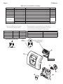
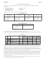
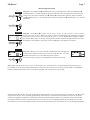
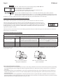
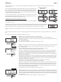
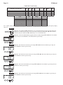
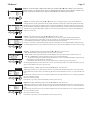
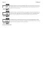
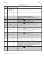
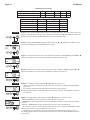
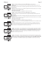
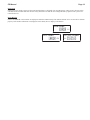
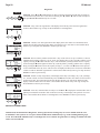
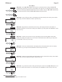
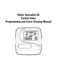
Water Specialist PR
Control Valve
Programming and Cover Drawing Manual
Page 2
PR Manual
PR Manual
Page 3
Table of Contents
PR Front Cover and Drive Assembly.............................................................................................................................4
OEM General Programming Instructions ......................................................................................................................5
OEM Configuration Setup .............................................................................................................................................7
OEM Softener System Setup .......................................................................................................................................10
Setting Options Table ...................................................................................................................................................13
OEM Filter System Setup ............................................................................................................................................14
Installer Display Settings .............................................................................................................................................16
User Display Settings...................................................................................................................................................17
Diagnostics...................................................................................................................................................................20
Valve History ...............................................................................................................................................................21
Page 4
PR Manual
PR Front Cover and Drive Assembly
Drawing No.
1
2
3
4
5
6
Order No.
V3692-01PW
V3107-01
V3106-01
V3757PR-BOARD
V3110
V3109
V3186
V3186EU
V3186UK
V3186-01
V3690
Not Shown
Not Shown
Description
WS1LP FRONT COVER ASY PURITAN HSBY/BLK
WS1 MOTOR
WS1 DRIVE BRACKET & SPRING CLIP
WS1THRU2L/2 PR PC BOARD REPLACE
WS1 DRIVE GEAR 12X36
WS1 DRIVE GEAR COVER
WS1 AC ADAPTER 110V-12V
WS1 AC ADAPTER 220-240V-12V EU
WS1 AC ADAPTER 220-240V-12V UK
WS1 AC ADAPTER CORD ONLY
WS1LP DRIVE BACK PLATE
U.S.
120 V AC
60 Hz
12 V AC
500 mA
When replacing the battery, align
positives and push down to fully seat.
1
1
Relay Specifications: 12V DC Relay with a coil resistance not
less than 80 ohms. If mounting the relay under the cover check
for proper mounting location dimensions on the backplate.
Refer to Control Valve Service Manual
for other drawings and part numbers.
AC Adapter
Supply Voltage
Supply Frequency
Output Voltage
Output Current
Quantity
1
1
1
1
3
1
International
230V AC
50 Hz
12 V AC
500 mA
Correct
Battery
Orientation
Wiring For Correct On/Off Operation
PC Board Relay Terminal Block
Relay
RELAY1
Coil COM
Coil +
RELAY2
Coil -
Battery replacement is
3 volt lithium coin cell
type 2032.
Battery Fully Seated
4
1
See page 6 for this
button’s function
5
6
2
3
PR Manual
Page 5
OEM General Programming Instructions
The control valve offers multiple procedures that allow the valve to be modified to suit the needs of the installation. These
procedures are:
•
•
•
•
OEM Configuration Setup
OEM Softener System Setup
OEM Filter System Setup
Installer Display Settings
•
•
•
User Display Settings
Diagnostics
Valve History
Tables 1 and 2 show cycle order when the valve is set up as a softener or filter.
Table 1
Regeneration Cycles Softening
Downflow Regenerant
Refill After Rinse
1st Cycle:
2nd Cycle:
3rd Cycle:
4th Cycle:
5th Cycle:
WS1PR only
Upflow Regenerant
Refill After Rinse
Downflow Regenerant
Prefill
1st Cycle:
2nd Cycle:
3rd Cycle:
4th Cycle:
5th Cycle:
Backwash
dn Brine
Backwash
Rinse
Fill
1st Cycle:
2nd Cycle:
3rd Cycle:
4th Cycle:
Fill
Softening
Backwash
dn Brine
Rinse
UP Brine
Backwash
Rinse
Fill
WS1PR only
Upflow Regenerant
Prefill
1st Cycle:
2nd Cycle:
3rd Cycle:
4th Cycle:
5th Cycle:
Fill
Softening
UP Brine
Backwash
Rinse
Table 2
Regeneration Cycles Filtering
Downflow Regenerant Refill After Rinse
st
1 Cycle:
2nd Cycle:
3rd Cycle:
4th Cycle:
5th Cycle:
No Regenerant
st
Backwash
dn Regenerant Draw
Backwash
Rinse
Fill
1 Cycle:
2nd Cycle:
Backwash
Rinse
The control valve with a water meter can be set for Demand Initiated Regeneration (DIR) only, Time Clock operation only or DIR and Time Clock which ever
comes first, depending upon what settings are selected for Day Override and Gallon Capacity.1 See Table 3.
If a control valve does not contain a meter, the valve can only act as a time clock, and day override should be set to any number and gallon capacity should be set
to off.
Table 3
DIR/Time Clock Options
DIR
Time
Clock
Yes
Yes
Yes
Yes
Yes
Yes
Yes
Settings2
Filter
Reserve Capacity
Automatically calculated
If desired enter a value less than
estimated capacity
Automatically calculated
If desired enter a value less than
estimated capacity
None
Softener
Regenerant
Backwash Only
Yes
Yes
Yes
Yes
Yes
Days to REGEN
Gallon
Capacity
Off
Auto
Off
Any Number
Any Number
Auto
Yes
Yes
Yes
Any Number
Any number
Yes
Yes
Yes
Any Number
Off
For DIR Softeners, there are two options for setting the Gallons Capacity. The Gallons Capacity is automatically calculated if set to AUTO. Reserve Capacity is
automatically estimated based on water usage if AUTO is used. The other option is to set the Gallons Capacity to a specific number. If a specific number is set,
reserve capacity is zero, unless the value is manually set (i.e. the manufacturer intentionally sets the gallon capacity number below the calculated capacity of the
system).
A unique feature of this control valve is the ability to display actual water usage for the last 63 days. The values are initially stored as “----”. This
means the value is unknown. As days pass values are stored as “0” for no flow or the actual number of gallons. The counting of the gallons starts at the
regeneration time. If no regeneration time can be set (i.e. when the valve is set for immediate regeneration) the counting of gallons starts at 12 a.m. Day
1 is yesterday, day 2 the day before yesterday, etc. As new values are added the oldest history disappears.
Another unique feature is that the valve automatically calculates a reserve capacity when set up as a softener with “Gallons Capacity” set to “AUTO”
and the “Regeneration Time Option” set to “DELAY REGEN” or “DELAY + IMMEDIATE”. The actual reserve capacity is compared to the gallons
capacity remaining immediately prior to the preset regeneration time. A regeneration will occur if the actual reserve capacity is less than the gallons
capacity remaining. The actual reserve capacity is calculated by using the estimated reserve capacity and adjusting it up or down for actual usage.
The estimated reserve capacity for a given day of the week is the maximum value stored for the last three non-trivial water usages (i.e. more than 20
gallons/day) in seven day intervals.
1
2
See Installer Display Settings, OEM Softener System Setup and OEM Filter System Setup for explanations of Day Override and Gallon Capacity.
Days to REGEN and Gallon Capacity can not both be set to “OFF” at the same time.
Page 6
PR Manual
To “lock out” access to diagnostic and valve history displays and modifications to settings except hardness, day override, time
of regeneration and time of day by anyone but the manufacturer, press ▼, NEXT, ▲, and CLOCK in sequence after settings are
made. To “unlock”, so other displays can be viewed and changes can be made, press ▼, NEXT, ▲, and CLOCK in sequence.
When in operation normal user displays such as time of day, volume remaining before regeneration, present flow rate or days
remaining before regeneration are shown. When stepping through a procedure, if no buttons are pressed within five minutes, the
display returns to a normal user display. Any changes made prior to the five minute time out are incorporated.
To quickly exit OEM Softener Setup, OEM Filter Setup, OEM Configuration Setup, Installer Display Settings, Diagnostics or
Valve History press CLOCK. Any changes made prior to the exit are incorporated.
To clear the Service Call reminder, press the ▲ and ▼ buttons simultaneously while CALL is displayed.
When desired, all information in Diagnostics, the Program and User Settings may be reset to defaults when the valve
is installed in a new location. To reset, press NEXT and ▼ buttons simultaneously to go to the Softening/Filtering Type
screen. Press ▲ and ▼ simultaneously to reset Diagnostics to zero and the Program and User Settings to defaults. The time
will be reset to 12:00 P.M.
Sometimes it is desirable to have the valve initiate and complete two regenerations within 24 hours and then return to the preset
regeneration procedure. It is possible to do a double regeneration if the control valve is set to “DELAYED REGEN” or “DELAY
+ IMMEDIATE” in OEM Softener System Setup or OEM Filter System Setup. To do a double regeneration:
1. Press the “REGEN” button once. REGEN TODAY will flash on the display.
2. Press and hold the “REGEN” button for three seconds until the valve regeneration initiates.
Once the valve has completed the immediate regeneration, the valve will regenerate one more time at the preset regeneration time.
Proportional Brining
If the system is set up as a prefill 1” upflow softener the control valve can also be set to normal or proportional brining.
This step will appear after Step 7S and before Step 8S if the system is set up as a prefill
upflow softener. The following options can be selected:
• NORMAL FILL - System always prefills with the salt level selected.
• PROPORTIONAL FILL - If proportional brining is selected, the actual salt fill time will
be calculated by dividing the actual volume of treated water used by the full volumetric
capacity, then multiplying this value by the maximum salt fill time.
Press NEXT to go to the next step. Press REGEN to return to the previous step.
Backlight Control
As an energy-saving feature, the control will automatically turn off the display illumination after 5 minutes of keypad inactivity,
or 1⁄2 minute after the last use of treated water. Any further keypad activity or water use will re-illuminate the display for 1⁄2 or 5
minutes. The Energy Saver feature default is ON.
The Master Illumination button is located in the lower right hand portion of the board. The purpose of the button is to manage
the keypad backlights and the Energy Saver feature. When the keypad backlights are OFF, pressing and holding this button for
about 5 seconds will turn the lights ON, and turn the energy-saver feature OFF, which will be indicated with a display “ENERGY
SAVER OFF”. If the button is not held until the Energy Saver Off display is shown, the backlights for the display and the
keypad will both go OFF after 5 minutes of no keypad activity. (The keypad backlights will remain OFF until either the Master
Illumination or any keypad button is pressed to turn them back ON.)
PR Manual
Page 7
OEM Configuration Setup
STEP 1CS
STEP 2CS
Step 1CS – Press NEXT and ▼ simultaneously for 3 seconds and release. Then press NEXT and ▼
simultaneously for 3 seconds and release. If screen in Step 2CS does not appear in 5 seconds the lock
on the valve is activated. To unlock press ▼, NEXT, ▲, and CLOCK in sequence, then press NEXT
and ▼ simultaneously for 3 seconds and release. Then press NEXT and ▼ simultaneously for 3 seconds
and release.
Step 2CS – Use the ▲ or ▼ to select 1.0 for 1” valve, 1.25 for 1.25” valve, 1.5 for 1.5” valve, 2.0L for
2L valve or 2.0 for 2” valve3. When 2.0L or 2.0 is selected, an additional screen will appear. It is used to
select which size flow meter is to be used with the valve, 1.5, 2.0 or Variable Meter Calibration. When
the Variable Meter feature is selected, enter the desired number of pulses per gallon that the flow meter
will generate. Press NEXT to go to Step 3CS. Press REGEN to exit OEM cycle sequence.
STEP 3CS
Step 3CS – When 2.0L or 2.0 are selected, an additional screen will appear. It
is used to select which size flow meter is to be used with the valve, 1.5 or 2.0.
Variable meter pulses of 0.1-150.0 PPG can also be selected.
Press NEXT to go to Step 4CS. Press REGEN to return to previous step.
Note: When using the WS2 valve, if “2.0L” is set instead of “2.0”, when the valve is in regeneration and the piston drives to
the “DRAW” cycle the piston will stall and generate a 102 error code. Clear the error code by pressing “NEXT” and “REGEN”
buttons simultaneously until the valve resets, then re-program valve to proper valve type setting.
3
When using the WS2 control valve, the circuit board software must have valve selection choices of 2.0 and 2.0L. The WS2 valve
must be set for the 2.0 valve type during programming. If the software version does not have both the 2.0 and 2.0L selections,
consult your equipment supplier for a replacement circuit board. When using the WS2L valve with older version software that
does not have both 2.0 and 2.0L selection choices, the valve must be set to 2.0 during programming. If a WS2L valve is being
used with newer version software that has both 2.0 and 2.0L selection choices, the valve must be set to 2.0L during programming.
Page 8
PR Manual
STEP 4CS
Step 4CS - Allows selection of one of the following using the ▲ or ▼ buttons:
• the Control Valve to have no hard water bypass;
• the Control Valve to act as an alternator; or
• the Control Valve to have a separate source during the regeneration cycle.
Select OFF when neither of these features are used.
Only use Clack No Hard Water Bypass Valves or Clack Motorized Alternating Valves (MAV) with these
selections. Clack No Hard Water Bypass Valves (1” or 1.25” V3070FF or V3070FM) are not designed to be used
with the alternator or separate source functions. The V3063 and V3063BSPT motorized alternating valves are not
designed to be used as a no hard water bypass or separate source inlet if the pressure differential is more than 60 psi.
Configuring the Control Valve for No Hard Water Bypass Operation:
Select nHbP for control operation. For no hard water bypass operation the three wire connector is not used.
Selection requires that a connection to MAV or a Clack No Hard Water Bypass Valve is made to the two pin
connector labeled MAV MTR located on the printed circuit board. If using a MAV, the A port of the MAV must
be plugged and the valve outlet connected to the B port. When set to nHbP the MAV will be driven closed before
the first regeneration cycle that is not FILL or SOFTENING or FILTERING, and be driven open after the last
regeneration cycle that is not FILL.
NOTE: If the control valve enters into an error state during regeneration mode, the no hard water bypass valve will remain in its current state
until the error is corrected and reset.
Selecting the Control Valve to act as an alternator:
Prior to starting the programming steps, connect the three pin wire to each control valve board’s three pin connector labeled “INTERCONNECT”. Also connect
the meter cord to either control valve to the three pin connector labeled “METER INPUT”.
Softener Valve Programming Steps
Set to ALTA
Set to ALTB
Connect ALTA valve to the MAV’s A port and connect
Connect ALTB valve to the MAV’s B port. No
OEM Cycle Sequence
Step 4CS
the MAV’s two pin wire connector to the two pin
connections between the ALTB valve and the MAV
connector labeled “MAV MTR” on the ALTA valve
are made.
Softener System Setup
Step 8S
Set to “AUTO”
Set to “AUTO”
Softener System Setup
Step 9S
Set regeneration time option to “IMMEDIATE”.
Set regeneration time option to “IMMEDIATE”.
Installer Display Setting
Step 3I
Set Days Between Regen to “OFF”
Set Days Between Regen to “OFF”
If set up for a filter, in Step 7F set Volume Capacity; in Step 9S select Regeneration Time Option “IMMEDIATE”; and in Step 3I select Days
Between Regen “OFF”.
Retracted
Extended
Valve “A” in Service Position =
MAV piston rod Retracted
Valve “B” in Service Position = MAV
piston rod Extended
Note: Clack Twin Alternator Operations
• Twin alternating systems can be programmed with a day override setting combined with the normal volume-based regeneration programming.
A twin alternating system in this configuration will then regenerate based on the volume used or the day override if there is a period of low
water usage.
• Twin alternating systems can be programmed as a time clock only based regenerating system. In this configuration, the days remaining are
counted only on the unit that is in service. The unit in Stand-by Mode only notes days in diagnostics, which results in time clock only twin
regeneration initiation.
• Twin alternating systems can be programmed for a delayed regeneration time. The system will allow an immediate transfer of the MAV to
switch tanks and place a fully regenerated unit in service once a unit becomes exhausted. The exhausted unit will then be placed into Stand-by
Mode and allowed to have a delayed regeneration at the pre-set time.
PR Manual
Page 9
NOTE: If the control valve is in an error state during regeneration mode the MAV will close the B port and keep open the A port until the error is
corrected and reset.
WS1, WS1.25, WS1.5,
For Clack Corporation alternator systems using the WS1, WS1.25, WS1.5 and WS2L valves,
WS2L Valves
WS2 Valve
there will be an option to delay the last two steps of regeneration (Rinse and Fill) until just
prior to a return to Service. Upon completion of the initial regeneration steps, the valve will
enter Standby. If the Delayed Rinse and Fill is not set to ON, the regeneration will proceed
normally, without any delays between cycles.
For Clack Corporation alternator systems using the WS2 valve, when NEXT is pressed after
selecting ALTA or ALTb, a display will allow the user to set the amount of pre-service rinse
time for the stand by tank just prior to returning to service.
Configuring the Control Valve for Separate Source Operation:
Select Separate Source Enabled for control operation. For separate source operation the three
wire connector is not used.
Selection requires that a connection to a Clack Motorized Alternator Valve (MAV) is made to the two pin connector labeled
MAV MTR located on the printed circuit board. The C port of the MAV must be connected to the valve inlet and the A port
connected to the separate source used during regeneration. The B port must be connected to the feed water supply.
When set to Separate Source Enabled the MAV will be driven closed before the first regeneration cycle, and be driven open after the last regeneration
cycle.
NOTE: If the control valve enters into an error state during regeneration mode, the MAV will remain in its current state until the error is corrected and
reset.
Press NEXT to go to Step 5CS. Press REGEN to return to previous step.
STEP 5CS
STEP 6CS
Step 5CS – Set Aux MAV Output to operate in one of three modes:
TIME – Output is activated at a set time after the start of regeneration, for a specified length of time.
SEP SOURCE: Allows Auxiliary MAV to switch positions before the start of regeneration and then switch back
at the end of regeneration.
OFF – Deactivates this output.
Press NEXT to go to Step 6CS. Press REGEN to return to previous step.
Step 6CS – Allows selection of an outside signal to control the initiation of a regeneration. Selection only matters
if a connection is made to the two pin connector labeled DP SWITCH located on the printed circuit board.
OFF – Feature not used
NOTE: In a twin alternating system each control must have a separate dP signal or dP
switch. One dP signal or one dP switch cannot be used for both controls.
ON 0 REG – If the dP switch is closed for an accumulative time of 2 minutes a regeneration will be signaled to
the unit. In a twin alternating system the MAV will transition first to switch units so that the signaled unit can
start regeneration. After the MAV is fully transitioned the regeneration begins immediately. Note: For WS1 –
WS2L control valves programmed for twin alternating: if the dP function “ON 0 REG” is set, the Delayed Rinse
and Fill feature is not available.
DELAY REG – If the dP switch is closed for an accumulative time of 2 minutes a regeneration will occur at the
scheduled delayed regeneration time. In a twin alternating system once the dP switch is triggered the PC Board
will display “REGEN TODAY” and when the delayed regen time comes the control will switch tanks and the
triggered unit will then go into regeneration.
Note: For WS1 – WS2L control valves programmed for twin alternating: if the dP function
“DELAY REG” is set, the Delayed Rinse and Fill feature is not available.
HOLD REG – If the dP switch is closed a regeneration will be prevented from occurring while there is switch
closure. In a twin alternating system the regeneration of a unit can be prevented upon switch closure. If the unit
depletes the capacity down to zero it will not be allowed to switch tanks to regenerate until the switch is open.
Note: For WS1 – WS2L control valves programmed for twin alternating the Delayed Rinse and Fill feature can
be set in conjunction with the “HOLD REG” if desired.
Press NEXT to go to Step 7CS. Press REGEN to return to previous step.
STEP 7CS
Step 7CS – Multiple Regenerations: Set the number of regenerations that will occur on the day of regeneration.
When this feature is active, two to four regeneration cycle times are possible on the scheduled multi-regeneration
day. Multi-regeneration days are determined by the number of days set in the Day Between Regen Setting (Step
3I). OFF will cancel this feature and limit the amount of Regen Times to one. Display is only viewed if Step 9S
or 5F is set to oFF.
Press NEXT exit Configuration Setup. Press REGEN to return to previous step.
Page 10
PR Manual
OEM Softener System Setup
Softening Cycle Programs
SOFTENING DN POST
SOFTENING DN PRE
SOFTENING UP POST (1” Valve only)
SOFTENING UP PRE (1” Valve Only)
Cycle
Backwash
Rinse
Draw (UP or DN)
Fill (all except 2” valve)
Softening
Fill (2” valve)
Fill
Soft
BW
X
X
X
X
X
X
Units
Minutes
Minutes
Minutes
LBS
Minutes
Minutes
Draw
UP
Draw
DN
X
X
X
X
Range
1-120 or OFF
1-120 or OFF
1-180 or OFF
0.1-200.0 or OFF
1-480 or OFF
01.-99.0 or OFF
BW
Rinse
Fill
X
X
X
X
X
X
X
X
X
Default
8
4
60
9.5
240
6.0
If a 1” upflow control valve is programmed for prefill the proportional brining display will appear after the grains capacity display.
(Step 7S).
STEP 1S
Step 1S – Press NEXT and ▼ simultaneously for 3 seconds and release. If screen in Step 2S does not
appear in 5 seconds the lock on the valve is activated. To unlock press ▼, NEXT, ▲, and CLOCK in
sequence, then press NEXT and ▼ simultaneously for 3 seconds and release.
STEP 2S
Step 2S – Choose the SOFTENING program desired (see table) using the ▼ or ▲ button. Press NEXT
to go to Step 3S. Press REGEN to exit OEM Softener System Setup.
STEP 3S
Step 3S – Select the time for the first cycle using the ▼ or ▲ button. Press NEXT to go to Step 4S.
Press REGEN to return to previous step.
STEP 4S
Step 4S – Select the time for the second cycle using the ▼ or ▲ button. Press NEXT to go to Step 5S.
Press REGEN to return to previous step.
STEP 5S
Step 5S – Select time for the third cycle using the ▼ or ▲ button. Press NEXT to go to Step 6S. Press
REGEN to return to previous step.
STEP 6S
Step 6S – Select the time for the fourth cycle using the ▼ or ▲ button. Press NEXT to go to Step 7S.
Press REGEN to return to previous step.
PR Manual
Page 11
STEP 7S
Step 7S – Select the LBS or MIN for the fifth cycle using the ▼ or ▲ button. When 2.0 is selected in
Step 2CS, FILL is on minutes. WS2 valves are shipped from the factory with a refill flow control of 2.2
gpm (8.3 lpm). Press NEXT to go to Step 8S. Press REGEN to return to previous step.
STEP 8S
Step 8S –Set Grains Capacity using the ▲ or ▼ button. The ion exchange capacity is in grains of hardness as
calcium carbonate for the system based on the pounds of salt that will be used. Calculate the pounds of salt using
the fill time previously selected. Grains capacity is affected by the fill time. The grains capacity for the selected
fill time should be confirmed by OEM testing. The capacity and hardness levels entered are used to automatically
calculate reserve capacity when gallon capacity is set to AUTO. Press NEXT to go to Step 9S. Press REGEN to
return to previous step.
STEP 9S
Step 9S – Set Volume Capacity using the ▲ or ▼ button. If value is set to:
• “AUTO” capacity will be automatically calculated and reserve capacity will be automatically estimated;
• “OFF” regeneration will be based solely on the day override set (see Installer Display Settings Step 3I); or
• “GALS BETWEEN REGEN” regeneration will be based off the value specified.
If “OFF” or a number is used, hardness display will not be allowed to be set in Installer Display Settings Step 2I.
See Setting Options Table for more detail. Press NEXT to go to Step 10S. Press REGEN to return to previous step.
STEP 10S
Step 10S – Set Regeneration Time Options using the ▲ or ▼ button. If value is set to:
• “DELAYED REGEN” means regeneration will occur at the preset time;
• “IMMEDIATE” means regeneration will occur immediately when the volume capacity reaches 0 (zero); or
• “DELAY + IMMEDIATE” means regeneration will occur at one of the following:
— the preset time when the volume capacity falls below the reserve or the specified number of days between
regenerations is reached whichever comes first; or
— immediately after 10 minutes of no water usage when the volume capacity reaches 0 (zero).
See Setting Options Table for more detail. This screen is not viewed if Step 8S is set to OFF. Press NEXT to go to
Step 11S. Press REGEN to return to previous step.
STEP 11S
STEP 12S
Step 11S: Set Relay 1 MODE operation using the ▲ or ▼ button. The choices are:
TIME: Relay activates at a set time after the start of a regeneration and then deactivates after a set period of time.
GALLONS: Relay activates after a set number of gallons have been used while in service, for a preset duration of
time.
REGEN GAL: Relay activates every set number of gallons have been used while in service or during regeneration
for a preset duration of time.
OFF: Deactivates this output.
Press NEXT to go to Step 12S. Press REGEN to return to previous step.
Step 12S: Set Relay 2 MODE operation using the ▲ or ▼ button. The choices are:
TIME: Relay activates at a set time after the start of a regeneration and then deactivates after a set period of time.
GALLONS: Relay activates after a set number of gallons have been used while in service, for a preset duration of
time.
REGEN GAL: Relay activates every set number of gallons have been used while in service or during regeneration
for a preset duration of time.
OFF: Deactivates this output.
Press NEXT to go to Step 13S. Press REGEN to return to previous step.
Page 12
PR Manual
STEP 13S
Step 13S: Set scheduled service alarm using the ▲ or ▼. Available options are OFF, TIME, ON GAL or BOTH.
Selecting OFF disables this feature. If OFF is selected press NEXT to exit OEM System Setup. If TIME, ON GAL
or BOTH is selected press NEXT to select the TIME and/or ON GAL values. See Steps 14S and/or 15S. Press
REGEN to return to the previous step.
STEP 14S
Step 14S: Status display – Time remaining until Service Alarm generation. Only appears if TIME or BOTH is set
in Step 13S. To change duration time, press and hold the ▲ and ▼ buttons for about 3 seconds until SET appears,
and the number flashes. Use ▲ or ▼ to select the new value. Press NEXT to either exit OEM Softener System
Setup or go to Step 15S if BOTH was selected in Step 13S. Press REGEN to return to the previous step.
STEP 15S
Step 15S: Status display – Volume remaining until Service Alarm generation. Only appears if GAL or BOTH
is set in Step 13S. To change the volume between service calls, press and hold the ▲ and ▼ buttons for about 3
seconds until SET appears, and the number flashes. Use ▲ or ▼ to select the new value. Press NEXT to exit OEM
Softener System Setup. Press REGEN to return to the previous step.
RETURN TO NORMAL MODE
PR Manual
Page 13
Setting Options Table
Filters should only use shaded options.
Volume
Capacity
Regeneration
Time Option
AUTO
DELAYED
REGEN
OFF
AUTO
DELAYED
REGEN
Any
number
Any
number
DELAYED
REGEN
OFF
OFF
DELAYED
REGEN
Any
number
Any
number
DELAYED
REGEN
Any
number
AUTO
Any
number
AUTO
3
IMMEDIATE
IMMEDIATE
DELAY +
IMMEDIATE
Day
Override
OFF
Result3
Reserve capacity automatically estimated.
Regeneration occurs when volume capacity falls below the reserve
capacity at the next Regen Set Time
Reserve capacity automatically estimated.
Regeneration occurs at the next Regen Set Time when volume capacity
falls below the reserve capacity or the specified number of days between
regenerations is reached.
Reserve capacity not automatically estimated.
Regeneration occurs at the next Regen Set Time when volume
capacity reaches 0.
Reserve capacity not automatically estimated.
Regeneration occurs at the next Regen Set Time when the specified
number of days between regenerations is reached.
Reserve capacity not automatically estimated.
Regeneration occurs at the next Regen Set Time when volume
capacity reaches 0 or the specified number of days between
regenerations is reached.
Reserve capacity not automatically estimated.
Regeneration occurs immediately when volume capacity reaches 0.
Time of regeneration will not be allowed to be set because regeneration
will always occur when volume capacity reaches 0.
OFF
Reserve capacity not automatically estimated.
Regeneration occurs immediately when volume capacity reaches 0.
Time of regeneration will not be allowed to be set because regeneration
will always occur when volume capacity reaches 0.
OFF
Reserve capacity automatically estimated.
Regeneration occurs when volume capacity falls below the reserve
capacity at the next Regen Set Time or regeneration occurs after 10
minutes of no water usage when volume capacity reaches 0.
AUTO
DELAY +
IMMEDIATE
Any
number
Any
number
DELAY +
IMMEDIATE
Any
number
Reserve capacity automatically estimated.
Regeneration occurs at the next Regen Set Time when volume capacity
falls below the reserve capacity or the specified number of days between
regenerations is reached or regeneration occurs after 10 minutes of no
water usage when volume capacity reaches 0.
Reserve capacity not automatically estimated.
Regeneration occurs at the next Regen Set Time when the specified
number of days between regenerations is reached or regeneration occurs
after 10 minutes of no water usage when volume capacity reaches 0.
Reserve capacity estimate is based on history of water usage
Page 14
PR Manual
OEM Filter System Setup
Filtering Cycle Programs
FILTERING DN POST
FILTERING BW/RINSE
Cycle
Backwash
Rinse
Draw (DN)
Fill (all except 2” valve)
Fill (2” valve)
BW
X
Units
Minutes
Minutes
Minutes
Gallons
Minutes
Draw DN
X
BW
X
X
Range
1-120 or OFF
1-120 or OFF
1-180 or OFF
0.01-20.00 or OFF
01.-99.0 or OFF
Rinse
X
X
Fill
X
Default
8
4
60
0.95
6.0
STEP 1F
Step 1F – Press NEXT and ▼ simultaneously for 3 seconds and release. If screen in Step 2F does not
appear in 5 seconds the lock on the valve is activated. To unlock press ▼, NEXT, ▲, and CLOCK in
sequence, then press NEXT and ▼ simultaneously for 3 seconds and release.
STEP 2F
Step 2F – Choose the FILTERING program desired using the ▼ or ▲ buttons. Press NEXT to go to
Step 3F. Press REGEN to exit OEM Filter System Setup.
STEP 3F
Step 3F – Select the time for the first cycle (which in this example is BACKWASH) using the▼ or ▲
button. Press NEXT to go to Step 4F. Press REGEN to return to previous step.
STEP 4F
Step 4F – Select the time for the second cycle (which in this example is RINSE) using the ▼ or ▲
button. Press NEXT to go to Step 5F. Press REGEN to return to previous step.
STEP 5F
Step 5F – Set Volume Capacity using the ▼ or ▲ button. If value is set to:
• “OFF” regeneration will be based solely on the day override set (see Installer Display/Settings
Step 3I); or
• As a number, regeneration initiation will be based off the value specified.
See Setting Options Table for more detail. Press NEXT to go to Step 6F. Press REGEN to return to
previous step.
STEP 6F
Step 6F – Set Regeneration Time Options using the ▼ or ▲ button. If value is set to:
• “DELAYED REGEN” means regeneration will occur at the preset time;
• “IMMEDIATE” means regeneration will occur immediately when the volume capacity reaches 0
(zero); or
• “DELAY + IMMEDIATE” means regeneration will occur at one of the following:
— the preset time when the volume capacity falls below the reserve or the specified number of days
between regenerations is reached whichever comes first; or
— immediately after 10 minutes of no water usage when the volume capacity reaches 0 (zero).
See Setting Options Table for more detail. Press NEXT to go to Step 7F. Press REGEN to return to
previous step.
PR Manual
Page 15
STEP 7F
Step 7F – Set Relay 1 MODE operation using the ▼ or ▲ button. The choices are:
TIME: Relay activates at a set time after the start of a regeneration and then deactivates after a set
period of time.
GALLONS: Relay activates after a set number of gallons have been used while in service, for a preset
duration of time.
REGEN GAL: Relay activates every set number of gallons have been used while in service or during
regeneration for a preset duration of time.
OFF: Deactivates this output.
Press NEXT to go to Step 8F. Press REGEN to return to previous step.
STEP 8F
Step 8F – Set Relay 2 MODE operation using the ▼ or ▲ button. The choices are:
TIME: Relay activates at a set time after the start of a regeneration and then deactivates after a set
period of time.
GALLONS: Relay activates after a set number of gallons have been used while in service, for a preset
duration of time.
REGEN GAL: Relay activates every set number of gallons have been used while in service or during
regeneration for a preset duration of time.
OFF: Deactivates this output.
Press NEXT to go to Step 9F Press REGEN to return to previous step.
STEP 9F
Step 9F – Set scheduled service alarm using the ▼ or ▲. Available options are OFF, TIME, ON GAL
or BOTH.
Selecting OFF disables this feature. If OFF is selected press NEXT to exit OEM System Setup. If
TIME, ON GAL or BOTH is selected press NEXT to select the TIME and/or ON GAL values. See
Steps 10F and/or 11F. Press REGEN to return to the previous step.
STEP 10F
Step 10F – Status display – Time remaining until Service Alarm generation. Only appears if TIME or
BOTH are set in Step 9F. To change duration time, press and hold the ▼ and ▲ buttons for about 3
seconds until SET appears, and the number flashes. Use ▼ or ▲ to select the new value. Press NEXT
to either exit OEM Filter System Setup or go to Step 11F if BOTH was selected in Step 9F. Press
REGEN to return to the previous step.
STEP 11F
Step 11F – Status display – Volume remaining until Service Alarm generation. Only appears if GAL
or BOTH are set in Step 9F. To change the volume between service calls, press and hold the ▼ and ▲
buttons for about 3 seconds until SET appears, and the number flashes. Use ▼ or ▲ to select the new
value. Press NEXT to exit OEM Filter System Setup. Press REGEN to return to the previous step.
Page 16
PR Manual
Installer Display Settings
STEP 1I
STEP 1I - Press NEXT and ▲ simultaneously for 3 seconds.
STEP 2I
STEP 2I – Hardness: Set the amount of hardness in grains of hardness as calcium carbonate per
gallon using the ▲ or ▼ buttons. The default is 20 with value ranges from 1 to 150 in 1 grain
increments. Note: The grains per gallon can be increased if soluble iron needs to be reduced. This
display will not show if “FILTER” is selected in Step 2F or if ‘AUTO’ is not selected in Set Volume
Capacity in OEM Softener System Setup. Press NEXT to go to step 3I. Press REGEN to exit
Installer Display Settings.
STEP 3I
STEP 3I – Day Override: When volume capacity is set to “OFF”, sets the number of days between
regenerations. When volume capacity is set to AUTO or to a number, sets the maximum number of
days between regenerations. If value set to “OFF”, regeneration initiation is based solely on volume
used. If value is set as a number (allowable range from 1 to 28) a regeneration initiation will be
called for on that day even if sufficient volume of water were not used to call for a regeneration. Set
Day Override using ▲ or ▼ buttons:
• number of days between regeneration (1 to 28); or
• “OFF”.
See Setting Options Table for more detail on setup. Press NEXT to go to step 4I. Press REGEN to
return to previous step.
STEP 4I
STEP 4I – Next Regeneration Time (hour): Set the hour of day for regeneration using ▲ or ▼
buttons. AM/PM toggles after 12. The default time is 2:00 AM. This display will show “REGEN
IMMEDIATE ON ZERO GAL” if “IMMEDIATE” is selected in Set Regeneration Time Option
in OEM Softener System Setup Step 9S. Press NEXT to go to Step 5I. Press REGEN to return to
previous step.
When Step 6CS is set to a value of two to four, additional regeneration time settings will be viewed.
These displays are used to set additional times of day where a regeneration cycle may be initiated by
the control as needed. When this feature is active a number (#1 - #4) will be added to the upper right
corner of this display to indicate which of the additional regeneration time settings is currently being
viewed.
STEP 5I
STEP 5I – Next Regeneration Time (minutes): Set the minutes of day for regeneration using ▲ or
▼ buttons. This display will not be shown if “IMMEDIATE” is selected in Set Regeneration Time
Option in OEM Softener System Setup Step 9S. Press NEXT to go to Step 6I. Press REGEN to
return to previous step. When this feature is active a number (#1 - #4) will be added to the upper
right corner of this display to indicate which of the additional regeneration time settings is currently
being viewed.
RETURN TO NORMAL MODE
Contact Screens
From Step 4I, press and hold both the CLOCK and ▲ button to change phone number and banner text.
Phone Number - Set phone number using the ▲ or ▼ arrow. Press NEXT to forward to the
next digit. Press REGEN to return to previous digit.
Banner Text - Set the banner text up to a maximum of 44 characters. Use the ▲ or ▼ to
select letters of the alphabet or a number in the banner text. Press NEXT to forward to the
next character or to exit the Installer Display Settings.
PR Manual
Page 17
User Display Settings
General Operation
When the system is operating, one of six displays may be shown.
Pressing NEXT will alternate between the displays. One of the
displays is always the current time of day. The second display
is one of the following: days remaining or volume remaining.
Days remaining is the number of days left before the system goes
through a regeneration cycle. Capacity remaining is the gallons
that will be treated before the system goes through a regeneration
cycle. Pressing the ▼ button while in the Capacity Remaining or
Days Remaining displays will decrease the capacity remaining in
10 gallon increments or the Days Remaining in 1 day increments,
and will also increase the volume used impacting the recorded
values in Diagnostics Steps 3D, 4D and 5D and Valve History,
Step 4VH.
The third display shows the current treated water flow rate
through the system. The fourth display will display contact screen
information, if it was edited. The fifth display will show either dP
or hold if the dP switch is closed. The sixth display indicates the
user should call for service. The service display will not appear
if OFF is selected in Step 12S of OEM Softener System Setup.
To clear the Service Call reminder, press the ▲ and ▼ buttons
simultaneously while the number and banner text screen is
displayed.
If the system has called for a regeneration that will occur at the
preset time of regeneration, the words REGEN TODAY will
alternate with the header on the display.
If a water meter is installed, the water drop flashes on the display
when water is being treated (i.e. water is flowing through the
system).
Drop will flash while
water is being treated.
or
Regeneration Mode
Typically a system is set to regenerate at a time of low water usage. An example of a time with
low water usage is when a household is asleep. If there is a demand for water when the system is
regenerating, untreated water will be used.
When the system begins to regenerate, the display will change to include information about the step of
the regeneration process and the time remaining for that step to be completed. The current cycle display
will alternate with the regen time remaining screen. The system runs through the steps automatically
and will reset itself to provide treated water when the regeneration has been completed.
DISPLAYS
ALTERNATE
BEING VIEWED
Manual Regeneration
Sometimes there is a need to regenerate the system sooner than when the system calls for it, usually referred to as manual
regeneration. There may be a period of heavy water usage because of guests or a heavy laundry day.
To initiate a manual regeneration at the preset delayed regeneration time, when the regeneration time option is set to “DELAYED
REGEN” or “DELAY + IMMEDIATE”, press and release “REGEN”. The words “REGEN TODAY” will periodically be shown
on the display to indicate that the system will regenerate at the preset delayed regeneration time. If you pressed the “REGEN”
button in error, pressing the button again will cancel the request. Note: If the regeneration time option is set to “IMMEDIATE”
there is no set delayed regeneration time so “REGEN TODAY” will not activate if “REGEN” button is pressed.
To initiate a manual regeneration immediately, press and hold the “REGEN” button for three seconds. The system will begin to
regenerate immediately. The request cannot be cancelled.
Note: For softeners, if brine tank does not contain salt, fill with salt and wait at least two hours before regenerating.
Page 18
PR Manual
Set Time of Day
The user can also set the time of day. Time of day should only need to be set if the battery has been depleted because of extended
power outages or when daylight saving time begins or ends. If an extended power outage occurs, the time of day will flash on and
off which indicates the time of day should be reset. The non rechargeable battery should also be replaced.
STEP 1U
STEP 1U – Press CLOCK.
STEP 2U
STEP 2U - Current Time (hour): Set the hour of the day using ▼ or ▲ buttons. AM/PM toggles
after 12. Press NEXT to go to Step 3U.
STEP 3U
STEP 3U - Current Time (minutes): Set the minutes of the day using ▼ or ▲ buttons. Press NEXT
to exit Set Time of Day. Press REGEN to return to previous step.
RETURN TO NORMAL MODE
REGEN PENDING will be displayed in Alternator Systems whenever a unit is waiting to initiate the
first cycle step of regeneration.
STAND BY will be displayed in Alternator Systems when a valve is in Standby state.
DELAYED RINSE+FILL PENDING will be displayed whenever a zero-capacity tank has
transferred to an off-line state and is currently waiting to initiate the second portion of a regeneration
cycle. Viewed only when Delayed Rinse and Fill is set to ON.
PR Manual
Page 19
Power Loss
If the power goes out the system will keep time until the battery is depleted. If an extended power outage occurs, the time of day
will flash on and off which indicates the time of day should be reset and the non rechargeable battery replaced. The system will
remember the rest.
Error Message
If the word “ERROR” and a number are displayed contact the OEM for help. This indicates that the valve was not able to function
properly. If the number and banner text display has been edited, the two displays will alternate.
Page 20
PR Manual
Diagnostics
STEP 1D
STEP 1D – Press ▲ and ▼ simultaneously for three seconds. If screen in step 2D does not appear in
5 seconds the lock on the valve is activated. To unlock press ▼, NEXT, ▲, and CLOCK in sequence,
then press ▲ and ▼ simultaneously for 3 seconds.
STEP 2D
STEP 2D – Days, since last regeneration: This display shows the days since the last regeneration
occurred. Press NEXT to go to Step 3D. Press REGEN to exit Diagnostics.
STEP 3D
STEP 3D – Volume, since last regeneration: This display shows the volume of water that has been
treated since the last regeneration. This display will equal zero if a water meter is not installed. Press
NEXT to go to Step 4D. Press REGEN to return to previous step.
STEP 4D
STEP 4D – Reserve History Volume used for last 7 days: If the valve is set up as a softener, a meter is
installed and Set Volume Capacity is set to “Auto,” this display shows 0 day (for today) and the reserve
capacity. Pressing the ▲ button will show day 1 (which would be yesterday) and the reserve capacity
used. Pressing the ▲ button again will show day 2 (the day before yesterday) and the reserve capacity.
Keep pressing the ▲ button to show the capacity for days 3, 4, 5 and 6. The ▼ button can be pressed
to move backwards in the day series. This screen is not displayed if filter, time clock, meter immediate,
volume override or alternator regeneration is selected. Press NEXT at any time to go to Step 5D. Press
REGEN to return to previous step.
STEP 5D
STEP 6D
STEP 5D - Volume, 63-day usage history: This display shows day 0 (for today), day 1 (for yesterday),
etc., and the volume of water treated that day. Press the ▲ button to show the volume of water treated
for the last 63 days. If a regeneration occured on the day the letter “R” will also be displayed. This
display will show dashes if a water meter is not installed. Press NEXT at any time to go to Step 6D.
Press REGEN to return to previous step.
STEP 6D – Flow rate, maximum last seven days: Use the ▲ or ▼ to display the maximum flow rate in
gallons per minute that occurred in each of the last seven days. This display will equal zero if a water
meter is not installed. Press NEXT to exit Diagnostics. Press REGEN to return to previous step.
RETURN TO NORMAL MODE
When desired, all information in Diagnostics, the Program and User Settings may be reset to defaults when the valve
is installed in a new location. To reset, press NEXT and ▼ buttons simultaneously to go to the Softening/Filtering Type
screen. Press ▲ and ▼ simultaneously to reset Diagnostics to zero and the Program and User Settings to defaults. The time
will be reset to 12:00 P.M.
PR Manual
Page 21
Valve History
STEP 1VH
STEP 1VH – Press ▲ and ▼ simultaneously for three seconds and release. Then press ▲ and ▼
simultaneously and release. If screen in step 2VH does not appear in 5 seconds the lock on the valve is
activated. To unlock press ▼, NEXT, ▲, and CLOCK in sequence, then press ▲ and ▼ simultaneously
for 3 seconds and release. Then press ▲ and ▼ simultaneously and release.
STEP 2VH
STEP 2VH4 – Days, total since start-up: This display shows the total days since startup. Press NEXT
to go to Step 3VH. Press REGEN to return to previous step.
STEP 3VH
STEP 3VH – Regenerations, total number since start-up: This display shows the total number of
regenerations that have occurred since startup. Press NEXT to go to Step 4VH. Press REGEN to return
to previous step.
STEP 4VH
STEP 4VH – Volume, total used since start-up: This display shows the total gallons treated since
startup. This display will equal zero if a water meter is not installed. Press NEXT to go to Step 5VH.
Press REGEN to return to previous step.
STEP 5VH
STEP 5VH – Flow rate, Total Peak Flow: This display shows the maximum flow rate since startup.
Press NEXT to go to Step 6VH. Press REGEN to return to the previous step.
STEP 6VH
STEP 6VH – Total Errors: This displays the total number of errors detected since startup. Press NEXT
to go to Step 7VH. Press REGEN to return to the previous step.
STEP 7VH
STEP 7VH – Log of the last 10 Error Codes generated by the control. Press the ▲ or ▼ button to view
each error recorded. Press NEXT to exit Valve History. Press REGEN to return to the previous step.
RETURN TO NORMAL MODE
4
Values in steps 2VH through 7VH cannot be reset.
Page 22
PR Manual
PR Manual
Page 23
Page 24
Form No. V3435PR • 4/15/2011
PR Manual