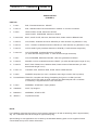
1
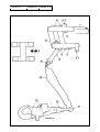
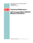
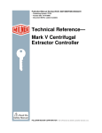
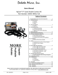
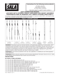
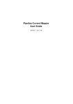
9000371
ISSUE F
PAGE I
Date of Issue: July 2003
®
RAILOK
®
RIGID VERTICAL SAFETY SYSTEM
INSTALLATION & SERVICING
INSTRUCTION MANUAL
SALA GROUP UK
OLD MILL ROAD,
PORTISHEAD,
BRISTOL BS20 7BX,
UNITED KINGDOM
TEL: +44 (0)1275 846119
FAX: +44 (0)1275 849114
email: [email protected]
AUSTRALIA
Sala Group pty Ltd,
20 Fariola Street, Silverwater,
Sydney NSW 2128, Australia
Tel: +61 29748 0335
Fax: +61 29748 0336
email: [email protected]
GERMANY
Sala Group GmbH
Flutstrasse 63, D-47533
Kleve, Germany
Tel: +49 2821 75330
Fax: +49 2821 753320
email: [email protected]
HONG KONG
Sala Group Ltd,
Room 1001, 10/F, Qualipak Tower,
122 Connaught Road West, Hong Kong
Tel: +852 2992 0381
Fax: +852 2858 8163
email: [email protected]
9000371
ISSUE E
PAGE II
CONTENTS
Page
Abbreviations .........................................................................
II
Safety .....................................................................................
III
Description .............................................................................
IV
Operation ...............................................................................
V
Specifications ........................................................................
VI
Installation
Ladder Rung Mounting .................................................... VIII
Ladder Stringer Mounting .................................................
X
Top Support Post .............................................................. XIII
Maintenance and Inspection .................................................. XV
User Instructions .................................................................... XVII
Amendment Record ..............................................................XVIII
ABBREVIATIONS
CEN
EDU
kg
kN
Central European Norm
Energy Dissipating Unit
kilogramme(s)
kilonewton(s)
m
mm
Nm
RVSS
metre(s)
millimetre(s)
Newton metre(s)
Rigid Vertical Safety
System
CE Approved to BS EN 353-1 1993
Railok is a registered trade mark of Sala Group Ltd.
© 2002
9000371
ISSUE E
SAFETY - READ THIS SECTION
FIRST !
PLEASE ENSURE THAT YOU HAVE THE LATEST EDITION OF THIS
DOCUMENT BEFORE USE - IF IN DOUBT CONTACT SALA GROUP LTD.
1.
PROCEDURES
To prevent personal injury or damage to the RVSS it is essential to
read, understand and comply with the procedures in this manual.
2.
INSTALLATION
Only components supplied by Sala Group Ltd may be used when
installing the system.
THE RAILOK TROLLEY, RAIL AND ALL ASSOCIATED PARTS ARE
FULLY CERTIFIED TO BS EN 353/1 1993.
UNDER NO
CIRCUMSTANCES MUST ANY PART BE ALTERED, MODIFIED OR
DISMANTLED (BEYOND THAT DESCRIBED IN THIS MANUAL)
SUCH ALTERATION, MODIFICATION OR DISMANTLING WILL
CONTRAVENE THE ABOVE CERTIFICATE AND COULD RESULT IN
SEVERE OR FATAL INJURY.
3.
SAFE WORKING
Observe safe working practice when installing the system. Wear
adequate protective clothing - including gloves, goggles, and safety
boots. Ensure that tools and equipment used are suitable and
adequate. When working at height whilst installing the system use a
separate means of fall arrest protection.
4.
LIMITATIONS OF USE
There is no limit to the number of users on the system at any one time,
however only ONE person, whose weight must not exceed 136kg, may
be attached to each EDU and only ONE trolley may operate on each
individual 3m length of rail at any one time.
PAGE III
9000371
ISSUE E
PAGE IV
DESCRIPTION
The RVSS is designed to prevent falls from fixed
ladders or structures to which it is attached. It is
comprised of two main elements : a rail,
permanently attached to the ladder or structure
and a trolley which runs on the rail (see fig 1). In
the free-running, unlocked position the outer ends
of the arms of the trolley are inclined upwards at
an angle of approximately 10o and only the rollers
are in contact with the rail (see fig 2). If the arms
fall below this position and reach the horizontal
the brake pads come into contact with the front
face of the rail and lock the trolley (see fig 2).
It is a CEN requirement that, in order to reduce
the adverse physical effects resulting from fall
arrest, a shock absorber is incorporated into the
system which ensures that the maximum force
exerted on the body does not exceed 6kN.
Therefore an Energy Dissipating Unit (EDU), to
which the user is attached by means of a selflocking hook, is fitted to the trolley. There are no
user serviceable or adjustable parts on the trolley.
Railok Systems supplied prior to the introduction
of the EDU should be upgraded by returning the
trolley to Sala Group Ltd. for the fitting of an EDU.
Each fixing point on the ladder or structure to
which Railok is fitted must be capable of
withstanding a minimum loading of 4kN. The
complete structure must be capable of
withstanding a load of 12kN per simultaneous
user.
Trolley
Rail
Energy
Dissipating
Unit
Automatic
Self-locking
Hook
Unlocked Position
FIGURE 1
FIGURE 2
Locked Position
9000371
ISSUE E
PAGE V
OPERATION
The lower extremity of the fixed rail terminates
approximately 0.5m above ground level. With the
arrow engraved on the outer face of the trolley
pointing ‘UP’ the trolley is positioned on the rail and
raised to the height required to enable the user to
attach the self-locking hook on the EDU to the front
‘D’ ring of a full body harness. The ladder may then be
climbed normally. If it is necessary to stop at any point
on the ladder the trolley must be raised as high as
possible above the user and allowed to lock on the
rail. The risk of free fall is thus eliminated.
A stop plate assembly, shown in figure 4, may be
fitted to the upper and lower extremities of the rail
to prevent removal of the trolley from the system.
This is particularly important where a hazard exists
at the top or bottom of the ladder system.
Where it is required to be detached from the system
at the top of a ladder the upper extremity of the fixed
rail can extend 1.3m above its top attachment point
on the ladder but must not be unsupported. The
user detaches himself from the trolley within this
length and the trolley either remains in position for
subsequent descent or is taken to the next rail
installation for continued ascent.
A stop bolt, shown in fig 3, may be fitted to the upper
and lower extremities of the rail to prevent
unintentional removal of the trolley from the system.
To detach the trolley, if stop bolts are fitted, the user
grips the nut (1) and depresses the stop bolt (2) to
allow the trolley to be removed. The user must not be
detached from the Railok system unless in a safe
area or connected to an alternative safety system.
FIGURE 3
FIGURE 4
9000371
ISSUE E
PAGE VI
SPECIFICATION
(FIGURE 5)
PART NO.
1.
P-1051
RAIL, Extruded Aluminium. HE30TF
2.
P-1051-S
RAIL, Stainless Steel. Recommended for maritime or corrosive conditions.
3.
P-1059
JOINT PLATE, PLAIN, Aluminium HE30TF
JOINT PLATE, THREADED, Aluminium HE30TF
4.
P-1059-8-25
BOLT, JOINT PLATE, M8 X 25, Stainless Steel, Grade 316A4 to BS5845/1991
5.
P-1055-X
CLIP, RUNG, Anodised Aluminium HE30TB (‘X’ suffix denotes rung diameter in mm)
6.
P-1054-X
CLIP, ‘J’ RUNG, Anodised Aluminium HE30TB (‘X’ suffix denotes rung diameter in mm)
7.
P-1053-X
CLIPS, ANGLE (pair) Anodised Aluminium HE30TB (‘X’ suffix denotes angle size)
8.
P-1052-X-Y
CLIP, STRINGER, Anodised Aluminium HE30TB
(‘X’ suffix denotes stringer width, ‘Y’ suffix denotes stringer thickness)
9.
P-1061
CLIP, STRINGER, Mild Steel, BS4360: 1986 43A, galvanised to BS729
10.
P-1058-X
SPACER, CLIPS, Anodised Aluminium HE30TF (‘X’ suffix denotes spacer length in mm)
11.
P-1056-X
BOLT, RAIL FIXING, M10, Stainless Steel, Grade 316A4 to BS6105/1981 (‘X’ suffix
denotes bolt length in mm)
12.
P-1057-10
LOCKNUT, M10, Stainless Steel, Grade 316A4 to BS6105/1981
13.
P-1060
WASHER, Neoprene (for use in conditions where high corrosion risk is present)
14.
R-1050/Z/3465 TROLLEY, Complete with Energy Dissipating Unit (part no. N-ED1) and selflocking hook. Each trolley is serial numbered and date stamped and a certificate
of conformity is supplied with the User Instructions.
15.
P-1064
ASSEMBLY, STOP BOLT, Spring loaded.
16.
C3000552
POST, Top Support.
17.
B4000444
ASSEMBLY, STOP PLATE.
18.
3000713
Top Reinforcement
NOTE:
For installation purposes the weight of a 3m length of aluminium rail with its attaching parts is approximately
4kg. For a stainless steel rail the weight is approximately 8kg.
Special fittings to suit applications not covered by the standard attaching parts can be supplied. Please
contact Sala Group Ltd for further information.
9000371
Rail Dimensions (mm)
A - 3048
B - 305
C - 1524
D - 2743
E - 93.5
ISSUE E PAGE VII
2.4m long aluminium
extrusion
18
Top Support Post
Dimensions (mm)
A - 1930
B - 275
C - 430
FIGURE 5
16
9000371
ISSUE E PAGE VIII
INSTALLATION
The adaptability of the means of attaching the
RVSS rail ensures that the system has a wide
range of applications the most common being
fixed ladders and lattice towers. Before installation
care must be taken to determine the most suitable
position in which the rail is to be fitted. When used
with a fixed ladder the rail is attached to the rungs
or stringers (i.e. the vertical side members). If the
rail is to be rung mounted it must be ascertained
that, if positioned on the ladder centre line,
adequate clearance exists on each side of the rail
for the safe positioning of the user’s feet on the
rungs. If this cannot be achieved the rail must be
off-set to one side or, alternatively, stringer
mounted. On lattice towers either the legs or the
struts may be used for fixing and similar care
regarding rail positioning should be taken.
The correct and safe operation of the RVSS
depends on the satisfactory installation of the rail
sections. Such an installation will have rail
sections that are not twisted and joints correctly
fitted so that the trolley moves smoothly over the
entire length of the rail.
The following examples are for ladder rung
attachment and ladder stringer attachment.
Standard attachment parts are used and
individual installations may differ from those
illustrated.
Ladder Rung Mounting
Rail Attachment
Figure 6 shows the first attachment point of the
rail to a ladder rung using a standard rung clip or,
as an alternative, a ‘J’ rung clip. There are three
groups of attachment points along a 3m section of
rail, each having four slotted holes. One hole in
each group must be used for attachment and each
attachment point dealt with in ascending
sequence. The hole selected must be that most
suitably positioned relative to the clip on the rung.
Ensure that if using the neoprene washer it is
placed on the fixing bolt with its radiussed outer
edge towards the rail and that before tightening
the locknut the head of the fixing bolt is recessed
into the central channel of the rail as shown in
detail ‘A’. Rail fixings must be tightened to a torque
of 45 Nm. In exceptional circumstances where it
proves impossible to use an existing attachment
point an 11mm hole may be drilled on the rail
centre line. However, the approval of Sala Group
Ltd must be sought before such action is taken.
When the first section of the rail is securely
attached the installer may use the trolley as the
ladder is climbed. However the trolley must not
pass beyond the rail joint until the joint plates are
securely fitted and the first attachment point of the
next rail is securely attached.
WARNING
If the RVSS is used in conditions where high
ambient temperatures occur, that is in excess of
20oC, it is important that the rail fixing bolts are
centrally positioned in the slotted fixing holes. If,
after installation in such conditions the rail shows
signs of buckling due to misalignment the fixing
bolts should be slackened and the rail reset. The
fixing bolts must then be retightened. The trolley
must not be used during this operation and an
alternative means of protection from falls be
employed.
Rail Joint
Figure 7 shows a typical rail joint. The joint plates
must be attached to the lower rail section and the
two fixing bolts finger tightened. The next rail
section is then slotted between the upward
projecting joint plates and the remaining two bolts
fitted. To accommodate the widest temperature
range in which the RVSS may be used it is
essential that a gap exists between adjoining rail
sections to allow for rail expansion. To set this gap
pull the upper rail upwards as far as possible
before tightening the four joint plate bolts to
25Nm.
WARNING
Where a ladder stops at a platform the rail must
not extend above platform level without support
and the last attachment point of the rail to the
ladder must be as near to the top of the ladder as
possible.
WARNING
®
Sala Railok is designed and manufactured by
Sala Group Limited to meet the relevant EN
specifications for rigid vertical safety systems
and carries CE approval.
However Sala Group Limited cannot be held
responsible for the integrity of the structure to
which the system is attached.
The installer should satisfy himself/herself that
the ladder and the mounting points or structure to
which the system is attached is capable of
withstanding the transferred loads which may be
applied in the event of a fall arrest.
9000371
ISSUE E PAGE IX
P-1051
20mm diam. rung
P-1055-20 P-1057-10
P-1054-20
P-1058-25
P-1057-10
P-1056-75
0.5m
Minimum
P-1056-40
P-1057-10
P-1051
Detail ‘A’
P-1060
(if required)
P-1058-25
P-1056-50
FIGURE 6
P-1051
Gap to be
maximum
obtainable
P-1059-8-25
P-1059
(Threaded)
P-1051
P-1059 (Plain)
FIGURE 7
9000371
ISSUE E
PAGE X
Stop Bolt Assembly Installation
Stop Plate Assembly Installation
The stop bolt assembly is fitted to the rail as
shown in figure 8. Tighten the nut on the
attachment bolt (1) to 45Nm. Adjust the position
of nut (2) on stop bolt (3) to obtain the dimension
shown. Fit locknut (4) so that at least one full
thread (5) is exposed when locked against nut (2).
If the top of the installation does not terminate at
the end of a complete section of rail it will be
necessary to drill two 11mm diameter holes. Use
the joint plate (6) as a template for hole
positioning aligning the end of the joint plate with
the end of the rail.
The stop plate assembly is fitted to the rail (as
shown in figure 9) using the existing joint plate
holes drilled in the rail. If the top of the intallation
does not terminate at the end of a complete rail
section it will be necessary to drill two 11mm
diameter holes. Use the spacer as a template for
the hole positions. Tighten the fixings to 25Nm.
Stop Plate
Spacer
22-23mm
View on arrow
View on arrow
FIGURE 8
Ladder Stringer Mounting
Rail Attachment
The three alternative standard methods of
attachment are shown in figure 10. On assembly
ensure that the stringer clips are a snug fit. For
further assembly instructions refer to Ladder
Rung Mounting.
Rail Joint
Refer to Rail Joint in Ladder Rung Mounting.
FIGURE 9
9000371
FIGURE 10
ISSUE E PAGE XI
9000371
ISSUE E PAGE XII
RAILOK TOP SUPPORT POST &
TOP REINFORCEMENT
Where a ladder stops at a platform or roof level the
Railok system must not extend above its last
attachment point. However, if it is required to extend
the rail beyond that attachment point Sala Group Ltd
can supply a support post to enable the rail to extend
as much as 1.3m above the platform or roof level.
The post may be fitted to either a rung or stringer
mounted Railok system.
The Top reinforcement extrusion takes the place of
the 25mm spacers, which must be discarded.
Excess material below the second mounting point
can be trimmed off if desired.
Alternatively if the extension is limited to a maximum
of 700mm an economical extruded top
reinforcement is available which can also be easily
retrofitted to existing installations.
Top Reinforcement Installation
The Top Reinforcement is supplied in 2.4m lengths,
to be drilled on site as required. It is shown in cross
section below.
When retrofitting to existing installations the locknuts
must be replaced with new ones.
The Top Reinforcement can be fitted to Rung
mounted or stringer mounted installations.
Two 10mm diameter holes are pre-drilled at top of
the extrusion to accept the end stop bolts which will
need to be 25mm longer than the standard bolts.
The extrusion must then be drilled to coincide with
the top two mounting points. The topmost mounting
point must be no more than 700mm from the top of
the rail and the top reinforcement.
Max.700mm
If the Top Reinforcement crosses a joint plate, the
extrusion should be drilled to accept the joint plate
bolts. The existing joint plate bolts should be
discarded. New longer bolts should be fitted through
the front joint plate and screwed into the threaded
back joint plate re-fitted at the back of the top
reinforcement extrusion.
9000371
ISSUE E PAGE XIII
RAILOK TOP SUPPORT POST
RUNG MOUNTING
Where a ladder stops at a platform or roof level
the Railok system must not extend above its last
attachment point. However, if it is required to
extend the rail beyond that attachment point Sala
Group Ltd can supply a support post to enable the
rail to extend as much as 1.3m above the platform
or roof level or a Top Reinforcement to extend up
to 700mm. These parts may be fitted to either a
rung or stringer mounted Railok system.
It is critical that, when attaching the support post
to the ladder rungs, the upper of the 3 attachment
flanges must be attached to the first rung BELOW
platform or roof level, see figure 11. One of the 3
bolts securing the post to the rungs must also
secure the rail. A typical post/rail to rung
installation is shown in figure 12.
Three
alternative holes are provided in each of the 3
pairs of flanges to accommodate a range of rung
pitch. Check that the post is vertical before
tightening the fixings to 45 Nm.
SUPPORT POST INSTALLATION
CAUTION
The support post weighs 12 kg and MUST be
secured safely whilst being installed.
WARNING
When attaching the Railok rail to the post a
minimum of 2 fixing bolts must attach it over the
length of the post.
The sizes of the post fixings, i.e. bolts, spacers
and clips, will be dependent on the ladder rung
and stringer dimensions. The installer should
calculate the sizes required prior to ordering
components from Sala Group Ltd.
Highest
permissible
attachment
rung
Top support
post
FIGURE 12
FIGURE 11
9000371
ISSUE E PAGE XIV
Platform level
Attach post
below this rung
FIGURE 13
STRINGER MOUNTING
It is critical that when attaching the support post to
the ladder stringer the upper of the 3 attachment
flanges must be positioned under the first rung
BELOW the roof or platform level, see figure 13.
One of the bolts securing the post to the stringer
MUST also secure the rail. A typical post/rail to
stringer installation is shown in figure 14. Three
alternative holes are provided in each of the pairs
of flanges to accommodate a range of stringer
thicknesses. Select the hole in the flange so that
the fixing bolt is as close as possible to the
stringer. Tighten fixings to 45 Nm.
RAIL TO
LADDER)
POST
ATTACHMENT
FIGURE 14
Flange 'A'
(ABOVE
The rail extending above the ladder must be
attached to a minimum of one of the upper 3
flanges. The optimum attachment point is flange
'A' as shown in figure 15. If this flange is used the
rail must not extend beyond the top of the post. If
flange 'B' or 'C' is used for attachment the rail
must not extend above the last attachment flange.
Tighten rail fixings to 45 Nm.
Flange 'B'
Flange 'C'
FIGURE 15
9000371
ISSUE E PAGE XV
MAINTENANCE
Pre-Use Checks
RAIL - Including joints and attachments.
Check that there is no corrosion on the rail and
its joints which may impair the smooth running of
the trolley. Check that all joints are secure and
that neither the joints or the rail are d i s t o r t e d .
This check cannot be made over the entire
length of the rail without climbing the ladder or
structure, therefore check the entire length of the
rail during initial ascent.
TROLLEY
Check that there is no corrosion which may
impair operation. Ensure that all fastenings are
secure and that the rollers rotate freely. Check
that there are no cracks, splits, bends or
distortion of any element of the trolley. Ensure
that trolley ‘hinges’ to and fro with light spring
assistance.
NOTE: Under normal operating conditions no
lubrication is required on the rail, however where
ice may form on the rail a protective coating may
be applied to the rail to prevent such formation.
In these circumstances ensure that, after use,
the trolley is thoroughly cleaned, particular
attention being give to the free rotation of the
rollers.
Annually
(Normal operating conditions)
Six Monthly (Maritime/corrosive conditions or
in conditions of intensive use)
RAIL
1. Remove
all
environmental
deposits
(especially salt encrustation) with a fibre (NOT
wire) brush or "Scotchbrite".
2. Ensure that all fixing clips are in place and
their fixings secure.
3. Check each rail to rail joint for security.
4. Check for localised or more extensive
distortion.If distortion is evident it is indicative
that the rail may have been subjected to a
fall arrest load. In this event rail that rail and
those immediately adjoining it together with
associated joint plates and rail attaching parts
MUST be replaced. If the distortion is on a
joint the rails on either side of that joint, the
joint plates and the rail attaching parts MUST
be replaced.
5. Check that there are no cracks, splits or
corrosion on the rail, its joint plates or the
attachments to the ladder or structure.
6. Check stop bolt operation (if fitted).
TROLLEY (See fig. 16)
1. Holding the trolley on its side pivot the top
plate forward. Release it and ensure that it
pivots fully rearwards with light spring
assistance.
2. Ensure the four brake ‘discs’ are in place and
correctly positioned.
3. Check that all rollers rotate freely.
4. Ensure that the rivets attaching the plates to
the upper and lower arms are secure by
attempting to pull the arms apart. No
movement of the arms is permissible.
5. Check the relative movement between the
upper and lower arms. The dimension shown
must not exceed 1.5mm.
6. (not illustrated) With the trolley in position on
the rail ensure that it will move upward freely
when lifted by the EDU snap hookand that it
locks on the rail when the hook is released.
Ensure that the trolley moves freely over each
rail joint.
7. Clean with a cloth and warm soapy water. DO
NOT IMMERSE. Lubricate rollers with water
repellant oil (e.g. WD40). Wipe off excess oil.
8. Check that the EDU ‘D’ ring locknuts are
secure.
9. Check that the EDU ‘D’ ring rubber sleeves
are in place and in sound condition.
10. Check that the outer sleeve of EDU is
correctly positioned and in good condition and
that no webbing has been pulled from the
sleeve.
11. Check that the webbing at the ‘D' ring and
snap hook is sound.
12. Check the snap hook for corrosion and ensure
that the locking mechanism functions
correctly. Check that the hook pivots freely on
its attachment ring.
13. (not illustrated) Proof loading must be carried
out by Sala Group Ltd to 6.67 kN (1500 lbs)
then repeat steps 1-8.
WARNING
If the trolley sustains a fall arrest it MUST be
withdrawn from service immediately, labelled to
indicate it is a quarantined component and
returned to Sala Group Ltd together with a note
indicating the nature and circumstances of the fall.
9000371
ISSUE E PAGE XVI
FIGURE 16
9000371
ISSUE E PAGE XVII
USER INSTRUCTIONS
The following instructions are supplied in twelve European Languages to each RVSS customer and it
is the customers’ responsibility to ensure that the intended user reads and understands these
instructions.
The user must wear a correctly fitted full body harness in order to use this equipment.
A.
Slide the trolley 1 onto the rail 2 with the arrow 3 pointing UP. Allow trolley to lock on the
rail at approximately chest height.
B.
To open hook safety catch: depress and hold hook lock release 4. Rotate lock 5. Attach
hook to harness ‘D’ ring and release safety catch.
C.
Ascend and descend the ladder in the normal manner.
D.
If it is necessary to stop on the ladder raise the trolley as high as possible and allow it to
lock.
E.
On disconnecting from the trolley when the top of the ladder is reached the trolley may
be left in position on the rail or removed and used for further ascent if required.
WARNING
Do NOT use any additional connector or lanyard with this equipment.
Use only on Railok installed system.
9000371
ISSUE E PAGE XVIII
AMENDMENT RECORD
DATE TODAY
ISSUE No.
AMENDED BY (NAME)
SIGNATURE
9000371
ISSUE E PAGE XVIV
9000371
ISSUE F PAGE XX
®
RAILOK ®
RIGID VERTICAL SAFETY SYSTEM
Installation Certificate
Sala Railok® is designed and manufactured by Sala Group Limited to meet the
relevant EN specifications for rigid vertical safety systems and carries CE approval.
However Sala Group Limited cannot be held responsible for the integrity of the
structure to which the system is attached.
The installer should satisfy himself/herself that the ladder and the mounting points or
structure to which the system is attached is capable of withstanding the transferred
loads which may be applied in the event of a fall arrest.
THIS IS TO CERTIFY
That the Railok® system fitted at (location) ..………………………..............................
.............................……………………………………………………………………………
Height of Ladder .............................………………………………………………………..
Rung Fixing / Stringer fixing (delete as necessary)
Maximum number of simultaneous users .............................……………………………
Has been installed in accordance with the instructions contained in the Sala Railok®
Installation & Service Manual (Sala Doc Ref # 9000371 Issue E) and the integrity of
the supporting structure and mounting points as described above has been verified
and approved.
Installed By (name) .............................…………………………………………………….
Company ..............................………………………………………………………………..
Signed ....................……………………………………..Date ...........…………………….
A copy of this certificate should be handed to the client on completion of an installation
and a photocopy returned to Sala Group Limited.