1
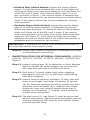
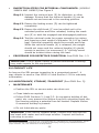
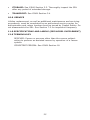
NOTIFIED BODY:
No. 0086
BSI Product Services
Kitemark House
Mayland Ave
Hemel Hempstead
HP2 4SQ
UK
9
EN360
SPECIFIC INSTRUCTIONS
FALL ARREST DEVICES
(Self Retracting Lifelines)
EN
Carefully read all instuctions for each component and General Instruction 5902392 before using this
equipment
FR
Lire attentivement toutes les instuctions pour chaque composant et l’Instruction générale 5902392
avant d’utiliser ce matériel
DE
Lesen Sie sorgfältig alle Anweisungen für jede Komponente sowie Allgemeine Anweisung 5902392
bevor Sie diese Ausrüstung verwenden
IT
Leggere attentamente tutte le istruzioni di ogni componente ele istruzioni generali 5902392 prima
di usare questo dispositivo
ES
Lea con atención todas las instrucciones para cada componente y la Instrucción general 5902392
antes de utilizar este equipo
DA
Læs omhyggeligt alle anvisningerne til hver komponent og Generel vejledning 5902392, inden dette
udstyr tages i brug
NO
Les nøye gjennom alle instruksjonene for hver komponent og Generelle instruksjoner 5902392 før
utstyret tas i bruk
FI
Lue jokaisen komponentin ohjeet ja Yleisohjeet 5902392 huolellisesti ennen näiden varusteiden
käyttöä
SV
Läs noggrant alla anvisningar för varje komponent och allmän anvisning 5902392 innan du
använder den här utrustningen
Form No: 5902198 Rev E
© Copyright 2008, DB Industries, Inc.
1
A
B
C
D
E
F
G
H
I
J
K
2
2
A
B
C
D
E
F
G
H
I
3
3
A
B
C
d
E
F
G
H
I
4
A
B
C
D
E
F
G
4
5
A
B
C
D
E
F
G
H
I
J
5
6
A
B
C
D
E
F
G
H
I
6
7
A
B
C
D
H
E
G
F
I
J
7
8
A
B
C
D
E
F
G
I
H
J
k
L
m
N
8
9
A
B
A
B
A
C
B
D
E
D
E
10
A
B
C
11 CM
36.4 CM
D
E
f
9
11
12
13
10
14
15
B
B
A
B
A
C
B
B
C
a
A
11
16
17
B
A
C
D
e
19
18
12
20
21
22
23
13
24
25
26
27
28
14
29
A
30
31
A
A
C
B
D
15
32
A
D
C
B
33
B
A
34
A
G
B
E
C
H
F
D
16
35
A
B
C
D
37
36
A
A
17
GB
Specific instructions—Self Retracting Lifelines
You have just purchased a Capital Safety Brand PPE to provide fall
protection for workers at height. We would like to thank you for your trust
in our equipment. To enjoy the safety and comfort you expect, please
keep and follow all instructions. All users and rescuers (see section 12
Terminology) are required to read this manual prior to use.
See ‘Glossary’ in General Instructions for Use and Maintenance (GIUM) for
identification of numbers in a white box.
1.0 Purpose/Descriptions
Capital Safety Self Retracting Lifelines (SRL) are components in
personal fall arrest systems (PFAS). These systems typically include
a full body harness, anchorage connector (i.e. carabiner) and the
SRL. Use in situations where worker mobility and fall protection is
needed (inspection work, general construction, maintenance work, oil
production, confined space work, etc.).
Some models feature a retrieval option*. These models have standard
fall arrest capabilities when used in their non-retrieval mode. In the
retrieval mode these models may be used for emergency rescue
(raising or lowering) of personnel within the capacity range stated
below. It is also permissible to use retrieval models for raising and
lowering of materials within the stated capacity range.
•
Sealed SRLs: Capital Safety Sealed SRLs incorporate a patented
sealed technology that separates all dynamic components from
foreign elements such as grease, moisture and dirt for safe
operation under all working conditions. See Figure 1: A-Anchorage
Handle, B-Instruction Label, C-Housing, D-Impact Indicator Label,
E-ID Label, F-Cable Guide, G-Lifeline, H-Bumper, I-Ferrule, J-SelfLocking Snap Hook.
◊ Sealed SRLs with Retrieval Feature: See Figure 2:
A-Retrieval Arm, B-Retrieval Handle, C-Handle Stowage Bracket,
D-Pull Ring, E-Operation Label, F-Shift Knob, G-Retrieval Label,
H-Pawl Cover, I-Torque Limiter Label.
•
Sealed-Blok™ SRLs: Includes cast aluminum housing and
heavy gauge stainless steel or aluminum end plates, anti-racheting
brake, built-in carrying handle (makes transport easy and provides a secondary “dropped objects protection” attachment point),
large pivoting anchorage handle and self-locking swivel hook with
impact indicator. See Figure 3: A-Anchorage Handle, B-Housing, CInstruction Label, D-Cable Guide, E-ID Label, F-Lifeline, G-Bumper,
H-RFID Tag; I-Self-Locking Snap Hook.
◊ Sealed-Blok™ SRLs with Retrieval: See Figure 4: A-Retrieval
Handle, B-Retrieval Label, C-Shift Knob, D-Locking Screw,
E-Retrieval Arm (crank arm), F-Winch Operating Label, G-RFID
Label.
18
IMPORTANT: Retrieval equipment may not be suitable for
applications requiring frequent or continual use as a material
hoist. Consult Capital Safety before using this product for such
applications. The retrieval models are not designed to be used for
general purpose work positioning or personnel-riding applications.
•
Ultra-Lok® SRLs: Capital Safety Ultra-Lok® SRLs come with a
durable glass-filled polyurethane housing, wire rope or web lifeline
and aluminum side plates for maximum durability and minimum
weight. The systems have an anti-racheting twin disc brake system
with an audio indicator to let you know it is functioning properly.
◊ ULTRA-LOK® WIRE & SYNTHETIC ROPE STYLE SRLs:
Includes swivel eye anchorage attachment point, self-locking
swivel snap hook with impact indicator, and choice of lifelines in
galvanized or stainless steel wire rope, or synthetic rope. Wire
rope lifeline lengths are available in 6.1, 9.1, 15.2 and 25.9 m.
Synthetic rope lifeline lengths are available in 6.1, 10.7, and
16.8 m. See Figure 5: A-Swivel Eye; B-Inspection Note Label,
C-Warning Label, D-Ultra-Lok Label, E-ID Label, F-Connections
Label; G-Wire or Synthetic Rope; H-Bumper; I-RFID Tag; J-RFID
Tag; K-Self-Locking Hook.
◊ LEADING EDGE SRLs: Includes swivel eye anchorage attachment point, self-locking swivel snap hook with impact indicator,
integral shock pack, and 9.1 m galvanized wire rope lifeline.
See Figure 6: A-Swivel Eye; B-Inspection Note Label, C-Warning
Label, D-Ultra-Lok Label, E-Connections Label; F-Wire Rope; GRFID Tag; H-Shock Absorber; I-Self-Locking Snap Hook.
• Note: Capital Safety SRL model 3504500 is designed for
use in applications where falls may occur over an edge,
such as roofing, leading edge construction, etc. This model
is especially suited for use with a fall arrest system, using
Capital Safety anchorage connectors intended for leading edge
work. We recommend the 2105503 Swiveling Concrete Roof
Anchor.
◊ ULTRA-LOK® WEB STYLE SRLs: Includes swivel eye anchorage attachment point, self-locking snap hook, and 2.54 cm wide
nylon web lifeline in lengths of 3.4 m and 6.1 m. See Figure 7:
A-Swivel Eye; Labels: B-Warning, C-ID, D-Impact Indicator,
E-Connections, F-Reverse Lifeline; G-RFID tag; H-Web Lifeline;
I-Indicator Fold; I-Connecting Hook.
•
SB Series SRLs: Includes heavy duty cast aluminum housing,
anti-racheting disk brake system, high strength pivoting steel
anchorage shackle, reserve lifeline retention and self-locking swivel
snap hook with impact indicator. See Figure 8: A-Shackle; B-Impact Indicator, C-SALA Label, D-Impact Indicator Label, E-Warning
Label, F-Specifications label, G-Instruction Label (left side), H-ID
19
Label, I-Instruction Label (right side); J-Wire Rope; K-RFID Tag;
L-Tear Drop Thimble; M-Self-Locking Swivel Snap Hook; N-Hook
options.
important: See GIUM Sections 1.1 and 1.3 before using this
equipment.
Important: Before using this equipment, record the product
identification information from the ID label (1) into the Equipment
Identification Sheet at the end of the GIUM.
2.0 Requirements: Installation and use of this equipment is restricted by the following limitations:
•
capacity: One person. At no time shall more than one person
connect to a single SRL for fall arrest applications. Retrieval applications can differ for each model. See Model Supplement for more
information.
•
Locking Speed: Situations which do not allow for an unobstructed fall path should be avoided. Examples include: working in
confined or cramped spaces, on slowly shifting material (such as
sand or grain) or on a low pitched roof where a worker may slide
instead of fall. These situations may not allow the body to reach
sufficient speed to cause the SRL to lock if a fall occurs. A clear
path is required to assure positive locking of the SRL.
•
environmental and physical hazards: Use of this
equipment in areas with environmental hazards may require additional precautions to reduce the possibility of injury to the user
or damage to the equipment. Hazards may include, but are not
limited to:
◊ Corrosion: Do not leave this equipment for long periods in environments where corrosion of metal parts could occur as a result
of vapors from organic materials. Use caution when working
around sewage or fertilizer because of their high concentration
of ammonia, which is very corrosive. Use near seawater or other
corrosive environments may require more frequent inspections
or servicing to assure corrosion damage is not affecting the performance of the product.
◊ Chemical: Solutions containing acids, alkali or other caustic
chemicals, particularly at elevated temperatures, may damage
DBI‑SALA SRLs. When working with such chemicals, frequent inspection of the entire SRL must be completed. Chemical damage
to the lifeline is difficult to detect and it is recommended that the
lifeline be replaced periodically to ensure safety. The lifeline may
only be replaced by an authorized service center.
◊ Heat: This equipment is not designed for use in high tempera20
ture environments. Provide protection for this equipment when
using near welding, metal cutting, or similar activities. Hot
sparks may burn or damage this equipment.
• Note: Synthetic rope lifelines are not flame proof and must
not be exposed to extreme heat. Do not use the following
in environments or contact surfaces over the specific
temperatures given:
• Spectra rope to 60° C
• Vectran rope to 120° C
◊ Electrical: Due to the possibility of electric current flowing
through the wire rope lifeline, use extreme caution when working near high voltage power lines.
Contact Capital Safety if you have questions about using
this equipment where environmental or physical hazards
exist.
important: Refer to applicable standards governing this
equipment for more information on personal fall arrest or restraint
systems and associated system components
•
compatibility of components: This equipment is designed
for use with Capital Safety approved components and subsystems
only. See also GIUM Section 1.12.
•
Compatibility of Connectors and making connections: Connectors (hooks, carabiners, D-rings) must be capable
of supporting at least 22 kN. Connectors must be compatible with
the anchorage and other system components and meet EN362
standards. See Figure 9: A-Anchorage; B-Connector; C-Anchorage
Connector, D-Mounting Bracket; E-Tripod Leg. See also GIUM Section 5 and Figures for EN362.
•
anchorage strength: The anchorage strength required is dependent on the application type. Anchors must meet requirements
of EN795. See also GIUM Section 12.
•
Horizontal system: In applications where an SRL is used
in conjunction with a horizontal system (i.e. horizontal I-beams
and trolleys), the SRL and horizontal system components must be
compatible. Horizontal systems must be designed and installed
under the supervision of a qualified engineer.
•
Optional retrieval system: When using an SRL with an
optional retrieval system, ensure the support structure (i.e. tripod,
davit arm) is compatible with the connection, operation, stability and strength of the SRL. See Figure 10-Optional Mounting for
Model 3400614: A-Hex Lock Nut, M12 x 1.75, Zinc Plated (ZP);
21
B-Hex Head Bolt, M12 x 1.75 x 25 cm, Metric Nut Class 8.8, ZP;
C-Mounting surface; D-use washers as required; E-Washer, 12
mm, ZP, 5 typical; F-Hex Head Bolt, M12 x 1.75 x 8 cm, Metric Nut
Class 8.8, ZP.
3.0 Training
It is the responsibility of the users of this equipment to understand
these instructions, and to be trained in the correct installation,
use, and maintenance of this equipment. This user manual is not a
substitute for a training program.
Important: Read GIUM Section 1.1 regarding training.
4.0 Planning
Before each use: Read GIUM Section 1.1 “Before each use” and
carefully inspect the SRL to assure it is in good working condition by
following the steps in Section 7.0. In addition do the following:
• Ensure all bolts are present and secure.
• Pull out the line and allow it to slowly retract. If there is any
hesitation in retraction, the unit should be returned to Capital
Safety for service.
• Check the locking action by pulling sharply on the line.
• Do not use if inspection reveals an unsafe condition.
Important: Read GIUM Sections 1.3, 1.4, 1.12 when planning
your system.
Planning: Plan your fall protection system before starting your
work. Consider factors that may affect your safety before, during, and
after a fall. The following list gives some important points to consider:
•
Anchorage: Select a rigid anchorage point (see Figure 9). See
more on anchorage strength in Section 2.0. Carefully select the
anchorage location to reduce free fall and swing fall hazards. Optional Mounting for Retrieval Systems is covered in Section 2.0.
IMPORTANT: Only SRLs that can be used in a horizontal mode
(indicated by labeling), such as the Leading Edge SRL, may be
anchored at foot level or above. See Figure 12. All other SRLs must
be anchored above the full body harness attachment (indicated by
labeling). See Figure 11
•
Swing Falls: Swing falls occur when the anchorage point is
not directly above the point where a fall occurs. See Figure 13.
The forces of striking an object in a swing fall may cause serious
injury. In a swing fall, the total vertical fall distance will be greater
than if the user had fallen directly below the anchorage point, thus
increasing the total free fall distance and the distance required
22
to safely arrest the user. The SRL will activate regardless of its
orientation relative to the user. Review your specific application
to determine what the appropriate work zone should be. Minimize
swing falls by working as directly below the anchorage point as
possible. Never permit a swing fall if injury could occur. If a swing
fall situation exists in your application contact Capital Safety before
proceeding.
•
FALL CLEARANCE: Ensure adequate clearance exists in your fall
path to prevent striking an object. The minimum clearance is 4.5
m from the dorsal D-ring level to the next level of obstruction or
object. See Figure 14. Additional clearance is required if potential
swing fall exists.
•
SHARP EDGES: Avoid working where the lifeline will be in contact
with or abrade against unprotected sharp edges. Provide protection
for the lifeline when possible. An energy absorbing component can
sometimes be added in-line to further protect the worker. Compatibility and total fall distance must be considered if this is done. Contact Capital Safety before using an in-line energy absorbing component or lanyard with an SRL.
IMPORTANT: Even though the Leading Edge SRL (Model 3504500)
provides additional protection from falls occurring over edges,
protection against cutting must be provided when working near
extremely sharp edges such as sheared, cold rolled, or flames cut
steel. Edge protection is not required over edges such as hot rolled
steel, steel decking, concrete, or wood.
•
RESCUE: If a fall occurs, the employer must have a rescue plan
and the ability to implement a rescue.
•
AFTER A FALL: Equipment which has been subjected to fall arrest
forces must be removed from service for inspection. See Section 7.
•
Other Considerations: Avoid working where your lifeline
may cross or tangle with that of another worker. Do not allow the
lifeline to pass under arms or between legs. Never clamp, knot or
otherwise prevent the lifeline from retracting or being taut. Avoid
slack line. Do not loop the lifeline around small structural members.
Important: Read and follow manufacturer’s instructions for
associated equipment (i.e. full body harness) used in your personal
fall arrest system.
Important: For special (custom) versions of this product,
follow the instructions provided in this manual. See supplement,
if included, for additional instructions when using a customized
product.
23
5.0 Assembly and Installation
•
BODY SUPPORT: When using Capital Safety SRLs a full body
harness (EN361) must be worn. For general fall protection use,
connect to the dorsal (back) D-ring between the shoulders.
◊ Retrieval Operations: It is recommended that a full body
harness be used to retrieve the victim, assuming their medical condition allows for such retrieval. Models are available with
retrieval connections (shoulder D-rings) on top of the shoulders
to aid in rescue operations.
warning: Body belts are not allowed for free fall situations.
They increase the risk of injury during fall arrest in comparison to
a full body harness. Limited suspension time and the potential for
improperly wearing a body belt may result in added danger to the
user’s health. See also GIUM Section 2.0
•
MAKING CONNECTIONS: When using a hook or carabiner to
make a connection, ensure roll-out cannot occur. See Section
2.0, “Compatibility of Connectors.” See Figure 15. Use a locking
snap hook or carabiner (A) that will completely close over the
anchorage (B) or anchorage connector (C). It is recommended
that the Model 340614 attach to a structure in a fixed position (vs.
hanging) with the hardware supplied. The mounting surface should
meet the anchorage strength requirements stated in Section 2.0,
“Anchorage Strength.” Follow the manufacturer’s instructions
supplied with each system component.
6.0 USE
See Figure 16. Connect the SRL (A) to a suitable anchorage (B).
Connect the self-locking snap hook (C), to the fall arrest or ladder
climbing attachment (D) on the full body harness (E). See Figure
17. Ensure connections are compatible and hook is fully closed and
locked. Once attached, the worker is free to move about within the
recommended working area at normal speeds. The lifeline should
extend smoothly and retract without hesitation. The lifeline must
remain taut at all times during normal use. If slack line condition is
created during normal use, the unit should be returned to Capital
Safety for service. If a fall occurs, the SRL will lock and arrest the fall.
Warning: Upon rescue, remove the SRL from use. See GIUM
Section 1.2.
Inspect as described in Section 7.0, “After Fall Arrest.” When working
with an SRL, always allow the lifeline to recoil back into the device
under control. A short tag line may be required to extend or retract
the lifeline during connection and disconnection. Allowing the lifeline
to be fully extended for long periods of time may cause premature
weakening of the retraction spring.
24
•
Retrieval System Operation (Models 3400101, 3400102,
3400301, 3400302, 3400501, 3400502): Figure 17 shows how
to activate the retrieval mode. Remove the retrieval handle on
the back side of the SRL by pushing the release button on top of
the handle and pulling upward. Install the pin into the hole on the
end of the retrieval arm. Rotate the arm assembly to the side
to access the shift knob. Lift the pull ring (on the shift knob) and
rotate it counterclockwise 1/8 turn and release. Rotate retrieval
arm clockwise to aid engagement. The shift knob should move
inward and rotate to a locked position when drive is fully
engaged.
◊ To Raise: Rotate retrieval arm counterclockwise.
◊ To Lower: Rotate retrieval arm clockwise. Keep tension on lifeline at all times (34 kg. minimum).
Important: A minimum load of 34 kg is required for lowering or
to pay out line.
IMPORTANT: If a fall occurs in the fall arrest mode and the worker
must be lowered to safety, raise the worker slightly to release the
locking pawls and lower the worker.
IMPORTANT: Do not continue to rotate the retrieval arm in the
lowering direction after the cable is fully extended. Spring damage
may occur.
◊ Disengagement of retrieval mode: Remove load from the
lifeline. Rotate the shift knob counterclockwise 1/8 turn, pull
ring out, rotate shift knob clockwise 1/8 turn. Release pull ring.
Remove retrieval handle from retrieval arm and stow in stowage bracket. Insert retrieval handle pin through handle and into
stowage bracket.
◊ Retrieval overload feature: SRLs incorporating the retrieval
feature (as shown in Figure 17) are provided with an overload
clutch which protects the drive components and the person
being raised from excessive force. This same feature provides
shock absorption for the user if a fall occurs when the retrieval
mode is engaged. The overload clutch is set to slip at approximately 227 kg. to allow for emergency rescue applications where
additional lifting capacity is required.
Important: Capacity for retrieval operation is 210 kg.
25
IMPORTANT: Operating the retrieval system at loads greater than
the rated capacity reduces the overall safety factor. Any unit which
has been used above the rated capacity must be removed from
service and returned to Capital Safety for inspection.
◊ Mounting Retrieval Models: The SRL retrieval models as
shown in figure 1 and 2, may be used with optional brackets
(Capital Safety Part Numbers 3401123 and 3401090) for mounting to the Capital Safety tripod, davit arm, or ladder mast. Follow the steps below for mounting and use of these brackets.
IMPORTANT: If mating bracket for tripod leg is not attached,
position clamp plate assembly in desired location on leg and tighten
bolts to 20 Nm. Do not overtighten.
Step 1. Attach the bracket to the SRL by inserting the two
furnished bolts through the holes in the SRL housing.
Attach nuts and secure. See Figure 18.
Step 2. After the bracket is secured to the SRL, position the
SRL bracket assembly onto mating bracket of tripod,
davit arm, or ladder mast. The slot in the end of SRL
bracket slides onto the pin extending out each side of
the mating bracket. Reposition the tripod leg bracket
as required for proper operating height. See Figure 19.
Step 3. With assembly resting on pin, pivot top of SRL inward
to align holes. Press in button on the end of the detent
pin and slide pin in fully to secure SRL assembly to
tripod, davit arm, or ladder mast. See Figure 20.
Step 4. Extend cable up support structure and over pulleys.
Reinstall detent pins near pulley to prevent cable from
sliding off pulleys. See Figure 21. Figures 22 and 23
show a completed attachment.
•
Retrieval SYSTEM OPERATION (Models 340854 and
340855): Figure 4 identifies key components of the retrieval
system. To activate retrieval mode, rotate the locking screw (D)
down completely to free the crank arm (E). Pivot the handle (A)
out from the stowed position. To engage the winch, pull and hold
the shift knob (C) in the unlocked position. Push the crank arm
(E) in to the engaged position and release the shift knob (C). If
needed, rotate the crank arm clockwise (lowering) to aid in gear
engagement.
◊ To Raise: Rotate the crank arm counterclockwise.
◊ To Lower: First crank the crank arm counterclockwise to release
the fall arrest brake, then crank clockwise.
26
important: A minimum load of 34 kg is required for lowering
or to pay out line. A force on the retrieval handle of up to 13 kg is
required to operate the winch when loaded to capacity.
caution: Stop cranking when line is fully extended or retracted.
Continued cranking can damage components.
◊ Disengagement of retrieval mode: Remove any load from
the lifeline. Pull and hold the shift knob in the unlocked position.
Pull the crank arm out to the disengaged position and release
the shift knob. Secure the crank arm with the locking screw. Pull
out on the retrieval handle and rotate the handle to the stowed
position.
◊ Retrieval overload feature: Winches on the SRL models (as
shown in Figure 4) do not incorporate an overload clutch to limit
the force applied to the drive components and the person being
raised. Care must be taken to avoid line slack while in rescue
mode. Also, the individual must be monitored during retrieval
to ensure they do not become stuck and subjected to excessive
force from continued lifting.
IMPORTANT: Operating the retrieval system at loads greater than
the rated capacity reduces the overall safety factor. Any unit which
has been used above the rated capacity must be removed from
service and returned to Capital Safety for inspection.
◊ Mounting Retrieval Models: The SRL retrieval models (as sjpwm om Figures 3 amd 4) may be used with an optional bracket
(Model 3401025) for mounting to the Capital Safety tripod, davit
arm, or ladder mast. Follow the steps below for mounting and
use of this bracket.
IMPORTANT: If mating bracket for tripod leg is not attached,
position clamp plate assembly in desired location on leg and tighten
bolts to 20 Nm. Do not overtighten.
Step 1.
Remove the three set screws plugging the holes in the
side of the SRL housing. See Figure 24
Step 2.
Attach the bracket to the SRL by inserting the three bolts
through the holes in the SRL housing. See Figure 25
Step 3.
After the bracket is secured to the SRL, position the SRL
bracket assembly onto mating bracket of tripod, davit
arm, or ladder mast. The slot in the end of SRL bracket
slides onto pin extending out each side of mating ladder
mast, davit arm, or tripod leg bracket. Reposition tripod
leg bracket as required for proper operating height. See
Figure 26.
27
7.0
Step 4.
With assembly resting on pin, pivot top of SRL inward
to align holes. Press in button on end of detent pin and
slide pin in fully to secure SRL assembly to tripod, davit
arm, or ladder mast. See Figure 27.
Step 5.
Extend cable up support structure and over pulleys.
Reinstall detent pins near pulley to prevent cable from
sliding off pulleys. See Figure 28.
INSPECTION
The i-Safe™ RFID tag on SRLs (A) can be used in conjunction with the
i-Safe handheld reading device and the web based portal to simplify
inspection and inventory control and provide records for your fall
protection equipment. See Figure 29.
•
FREQUENCY: Before each use inspect SRL according to the
inspection steps below. SRLs must be inspected by a competent
person, other than the user, at least annually. If you are a firsttime user, contact a Customer Service representative or if you
have already registered, go to: www.capitalsafety.com/isafe.html.
Follow instructions provided with your i-Safe handheld reader or
on the web portal to transfer your data to your web log. Record
the results of each formal inspection in the Periodic Examination
and Repair History in the GIUM (5902392) or use the i-Safe™
inspection web portal to maintain your inspection records. See
GIUM Section 4.
A record of annual service dates can be found on the SRL labels.
◊ After Fall Arrest: Inspect load impact indicator and entire SRL.
◊ After Use of Retrieval Mode: After raising or lowering, inspect
the load impact indicator and entire SRL. Applications which
require continuous raising and lowering may require increased
inspection and servicing frequency. Contact Capital Safety if you
have any questions regarding inspection frequency.
WARNING: See GIUM 1.2 if the SRL has been subjected to fall
arrest or impact forces.
IMPORTANT: Extreme working conditions (harsh environment,
prolonged use) may require increasing the frequency of inspections.
•
General INSPECTION STEPS:
Step 1.
Inspect for loose screws, bolts and bent or damaged
parts.
Step 2.
Inspect housing for distortion, cracks, or other damage.
UltraLok Models Only: Ensure the swivel eye is not
28
damaged or distorted in any way. Ensure the swivel eye
turns freely.
SB Series Only: Ensure the shackle moves freely and
is free from distortion, cracks, burrs and worn parts.
Ensure the athe nut is fully tightened.
Step 3.
Inspect the load impact indicator. This inspection is
dependent on the type of SRL used. Follow the detailed
instructions for your SRL type:
◊ UltraLok Cable and Rope Style SRLs: See Figure 30. Inspect
the impact indicator (A). In “normal mode” (B) you should look
for exposed color band (C) on the hook. If the hook is in the
“indicated mode” (D), an impact loading has occurred.
• Note: Do not attempt to reset impact indicator. Swivel will not
turn freely in “indicated mode.”
◊ SB SRLs: See Figure 31. Check the red impact indicator button
(A), to be sure it is flush with the housing. If the button is not
flush with the housing, the block has been deployed.
◊ UltraLok Web Style SRLs: See Figure 32. These SRLs incorporate an impact indicator in the web lifeline (A). The web near the
hook end (B) of the lifeline is folded onto itself and stitched with
red thread, forming a small loop (C). The stitched loop will pull
out at approximately 1.6 kN. If the red stitching is intact, the
SRL has not been impacted. If the red stitching has been broken
and the loop torn apart (D), the SRL has been impact loaded.
◊ UltraLok Leading Edge Style SRLs: See Figure 33. The
3504500 leading edge style SRLs incorporate an integral energy
absorbing component. Inspect the energy absorber to determine
if it has been activated. There should be no evidence of elongation (B). Ensure energy absorber cover (A) is secure and not
torn or damaged.
WARNING: If inspection reveals a defective condition, remove SRL
from service immediately and contact an authorized service center.
Step 4.
Lifeline should pull out and retract fully without
hesitation or creating a slack line condition. The lifeline
must be taught (under tension).
Step 4.
Ensure device locks up when lifeline is jerked sharply.
Lockup should be positive with no slipping.
Step 5.
The labels must be present and fully legible. See Model
Supplement.
Step 6.
Look for signs of corrosion on the entire unit.
Step 7.
Inspect lifeline.
29
◊ Wire Rope Models: See Figure 34. Inspect lifeline for cuts,
kinks (A), broken wires (B), bird-caging (C), corrosion, welding
splatter (D), chemical contact areas, or severely abraded areas.
Slide up cable bumper and inspect ferrules for cracks or damage
and inspect wire rope for corrosion and broken wires.
• Note: Replace the wire rope assembly if there are six or more
randomly distributed broken wires in one lay, or three or more
broken wires in one strand in one lay. A “lay” of wire rope is
the length of wire rope it takes for a strand (the larger groups
of wires) to complete one revolution or twist along the rope.
Replace the wire rope assembly if there are any broken wires
within 25mm of the ferrules.
◊ Web or Synthetic Rope Models: See Figure 34. Inspect lifeline
for concentrated wear, frayed strands (E), broken yarn, burns
(F), cuts (G), and abrasions. The lifeline must be free of knots
throughout its length. Inspect for excessive soiling (H), paint
buildup, and rust staining. Inspect for chemical or heat damage indicated by brown, discolored, or brittle areas. Inspect for
ultraviolet damage indicated by discoloration and the presence
of splinters and slivers on the lifeline surface.
• NOTE: All of the above factors are known to reduce rope
strength. Rope strength is reduced proportional to the crosssectional area of the rope damaged. Damaged or questionable
ropes must be replaced.
WARNING: Do not tie or knot lifeline. Avoid lifeline contact with
sharp or abrasive surfaces. Inspect lifeline frequently for cuts,
fraying, burns, or signs of chemical damage. Dirt, contaminants,
and water can lower dielectric properties of the lifeline. Use caution
near power lines.
Step 8.
Inspect connecting hooks, if present, for signs of
damage, corrosion, and working condition. Swivel should
rotate freely.
Step 9.
Inspect the reserve lifeline payout, if present, by
checking indicators:
◊ Wire Rope Lifeline Models (Excluding SB Series): See
Figure 35: A-Cable Guide; B-Cable Stop; C-Cable Guide Sleeve;
D-Bumper. See Figure 36: A-Reserve Lifeline Red Band. If a fall
has been arrested when most of the lifeline was out, it is possible that the reserve lifeline has been deployed. To inspect for
reserve lifeline deployment, pull lifeline out of the SRL until it
stops. If the red band indicator is visible, the reserve lifeline has
been deployed. If the reserve lifeline has not been deployed,
that portion is acceptable and the inspection can continue.
◊ SB Series Models: These SRLs do not have a reserve lifeline
feature.
30
◊ UltraLok Web Lifeline Models: Inspect the reserve lifeline
payout. If a fall has been arrested with most of the lifeline out,
the reserve lifeline may have been deployed. Pull the lifeline out
of the SRL until it stops. If the reserve lifeline label (F) is visible, as shown in Figure 7, the reserve lifeline is deployed and
the unit must be serviced by an authorized service center before
reuse. If the reserve lifeline has not been deployed, continue
with inspection.
◊ Synthetic Rope Lifeline Models: Inspect the reserve lifeline
payout. If a fall has been arrested, it is possible the reserve
lifeline has been deployed. To inspect for reserve lifeline deployment, pull lifeline out of the SRL until it stops. If the reserve
lifeline warning label (A) is visible, the reserve lifeline has been
deployed. See Figure 37. If the reserve lifeline has not been
deployed (the reserve lifeline label is not visible) that portion is
acceptable and the inspection can continue.
Important: If indicators are visible, the unit must be serviced by
an authorized service center before reuse.
Step 10. Inspect each system component or subsystem according
to manufacturer’s instructions.
•
INSPECTION STEPS FOR RETRIEVAL COMPONENTS: (MODELS
3400101, 3400102, 3400301, 3400302, 3400501, 3400502) See
Figure 2
Step 11. Inspect retrieval arm (A) for distortion or other damage.
Retrieval handle (B) should engage into retrieval arm
with ease and push button should work freely.
Step 12. Shift knob (F) should rotate freely when engaging/
disengaging. Pull ring (D) on shift knob should spring
back when released.
Step 13. Inspect retrieval mode for operation. To test, raise and
lower a test weight (sand bag) of between 34 kg and
141 kg. Retrieval operation should be smooth and even.
When the retrieval handle (B) is released, the weight
should not move and retrieval handle should stay in
position (no movement). A “clicking” sound should be
evident when raising load.
Step 14. The pawl cover (H) (see Figure 3) must be secure and
without deformation. Optional mounting bracket must be
securely attached to SRL and free from defects. Detent
pin must operate freely.
31
•
INSPECTION STEPS FOR RETRIEVAL COMPONENTS: (Models
340854 and 340855) See Figure 4
Step 11. Inspect the retrieval arm (E) for distortion or other
damage. Ensure that the retrieval handle (A) can be
rotated out and secured in the cranking position.
Step 12. Ensure the locking screw (D) can be tightened
completely.
Step 13. Ensure the shift knob (C) can be pulled out to the
unlocked position and then released, locking the crank
arm (E) in both the engaged and disengaged positions.
Step 14. Test the retrieval mode for proper operation by raising
and lowering a test weight of between 34-141 kg (sand
bag). Retrieval operation should be smooth and even.
When the retrieval handle (A) is released, the weight
should not move and the retrieval handle (A) should
remain in position (no movement). A “clicking”sound
should be evident when raising the load.
•
Procedure for Defective Condition: See GIUM Sec. 1.2.
Important: Only Capital Safety or parties authorized in writing
may make repairs to this equipment.
8.0 Product Life
As long as the SRL passes inspection by a competent person1, it
may remain in service. See GIUM 4.2 and Section 1.16 for warranty
information.
9.0 MAINTENANCE, STORAGE, Transport (See GIUM Sec. 3)
•
Maintenance
◊ Position the SRL so excess water can drain out.
◊ Clean labels as required.
◊ Follow GIUM Sections 3.1 and 3.2. An excessive buildup of dirt,
paint, etc. may prevent the lifeline from fully retracting back into
the housing causing a potential free fall hazard. Replace lifeline
if excessive buildup is present.
◊ Do not lubricate any parts.
Warning: If the lifeline contacts acids, remove unit from service
and wash with water and mild soap solution. Inspect unit before
returning to service.
1 Competent Person: An individual who is knowledgeable of a manufacturer’s recommendations, instructions, and manufactured component who is capable of identifying existing and predictable hazards in
proper selection, use, and maintenance of fall protection
32
•
STORAGE: See GIUM Section 3.3. Thoroughly inspect the SRL
after any period of extended storage.
•
TRANSPORT: See GIUM Section 3.4
10.0 Service
Lifeline replacement, as well as additional maintenance and servicing
procedures, must be completed by an authorized service center. An
authorization and return number must be issued by Capital Safety. Do
not disassemble the SRL. See Section 7.0 for inspection frequency.
11.0 Specifications and labels (See Model supplement)
12.0 Terminology
Rescuer: Person or persons other than the rescue subject
acting to perform an assisted rescue by operation of a rescue
system.
Competent person: See GIUM Section 16.
33
78
3000057
3000058
3000059
3000061
3000070
3000071
3000072
3000075
3000076
3000077
3000150
3000151
3000152
3000153
3103116
3103229
3400001
3400002
3400101
3400102
3400201
3400202
3400301
3400302
3400401
3400402
3400501
3400502
3400518
3400519
3400614
3400803
3400804
3400854
3400855
3504430
3504431
3504432
3504433
3504434
3504436
3504437
3504438
3504439
3504440
3504450
3504451
3504452
3504480
3504485
3504486
3504487
3504488
3504500
3505694
3505695
3505696
3505697
3505698
3505699
7211510
7211511
7211512
7211513
7211514
7211515
A Capital Safety Company
CSG USA
3833 Sala Way
Red Wing, MN 55066-5005
CSG Canada Ltd.
260 Export Boulevard
Phone: 651.388.8282
Fax: 651.388.5065
[email protected]
Mississauga, Ontario L5S 1Y9
Canada
Phone: 905.795.9333
Fax: 905.795.8777
[email protected]
CSG Northern Europe Ltd.
7 Christleton Court • Stuart Rd.
CSG EMEA (France)
CSG Asia Pte Ltd.
CSG (Aust) Pty Ltd.
Le Broc Center
Z.I. 1ère Avenue-5600 M
BP 15 • 06511 Carros Cedex
Phone: +33 (0)4 97 10 00 10
Fax: +33 (0)4 93 08 79 70
[email protected]
No. 6, Tuas Avenue 18
Singapore 638892
Phone: +65 6558 7758
Fax: +65 6558 7058
[email protected]
www.capitalsafety.com
Manor Park • Runcorn
Cheshire WA7 1ST • UK
Phone: +44 (0) 1928 571324
Fax: +44 (0) 1928 571325
[email protected]
20 Fariola Street • Sliverwater
Sydney, NSW 2128
Australia
Phone: +61 (2) 9748 0335
Fax: +61 (2) 9748 0336
[email protected]