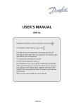
1
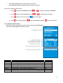
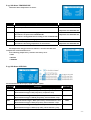
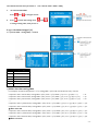
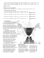
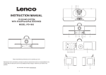
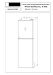
 Air to Water Heat Pump EVI Split Combo Type Service Manual Before operation this product, please read the instructions carefully and save this manual for future. Thank you for choosing our quality product. Please read this manual carefully before use and follow the instructions to operate the unit in order to prevent damages on the device or injuries to staff. Specifications are subject to change with product improvements without prior notice. Please refer to the specification sticker on the unit for upgraded specifications. Heat pumps stand out for their compactness and high performances: operation down to ‐20’c. They are reversible and can be used for heating and for cooling in summer. They can also be used for fan coil units. Heat pump has indoor unit and outdoor unit. Outdoor unit is connected to indoor module by copper connective pipe. The outdoor unit has: ‐ Air‐side heat exchanger with copper pipes and aluminum fins, complete with grid protection. ‐ Axial fan The inside unit has: ‐ Electronic expansion valve ‐ Water‐side shell‐tube heat exchanger complete with water‐flow‐switch. ‐ Outdoor temperature probe for control and climatic compensation of the water set point ( heat curve ). ‐ LCD controller with thermostat function, displaying and setting the operating parameters. ‐ Electronic control panel equipped with electrical terminal boards for connective external consents. ‐ Structure in painted galvanised stell complete with condensation tray. ‐ Compressor: scroll EVI hermetic compressor complete with thermal protection. ‐ Circulation pump ‐ Auxiliary electrical heater ‐ 3‐way‐water‐valve: the motorised reversal valve with connector for sanitary hot water tank Optional: ‐ Buffer tank: used to limit operation of the compressor in short cycles and to provide a reserve for the defrosting phase on reversible air/water heat pump. ▌Working temperature range: ‐ in heating mode: Outside air: ‐20 ~45°C Water: +18/+55’c ‐ in cooling mode : Outside air: +15 ~45°C Water: +7/+25°C Maximum operating water pressure: 7bar. When install the unit, be sure to check whether the selection of installation place, power supply specifications, usage limitation(piping length, height differences between indoor and outdoor units, power supply voltage and etc.) and installation spaces
-1-
Content 4 –5 6 7 8 9 10 10 11 11 12 13‐14 14‐15 15 16 16 16‐18 18 19 19‐20 20‐21 21 22 23 24 24 24 24 24 24‐25 25 25 25 -2-
26‐28 28‐29 29 29‐30 31 31 31 32 32 32 33 33 33 33 33 33‐34 35‐39 40 40 41 42 43 44 44 45‐46 -3-
1 Safety precautions If heat pump is not running in the winter, it is necessary to keep power supply connected for Anti‐freeze protection. In cold weather (≤ 0°C), if heat pump is no longer needed, do drain out all the water inside the system. 1.1 Safety precautions ‐ Warning ‐ suggestion ‐ prohibition Once abnormality like burning smell Be sure to pull out the power plug Make sure to use a dedicated power occurs, please cut off the power and drain the indoor unit and water line for the heat pump only. Do not supply immediately and then contact tank when unit is not in use for a long add other appliances to the line. with service center. time. Otherwise, the accumulated dust may cause overheating fire or freeze of water tank or coaxial heater exchanger in winter. If the abnormality still exists, the unit may be damaged and electric shock or fire may result. Before installation, please see if the Don't operate the unit with wet hand. Never damage the electric wire or use voltage of local place accords with the one which is not specified. that on nameplate of unit and capacity of power supply, power cord or socket is suitable for input power of this unit. Otherwise, it may cause electric shock. Otherwise, it may cause Overheating or fire. Before cleaning please cut off the The power supply must adopt special The unit must be earthed to avoid any power supply. Otherwise, it may circuit with leakage switch and risks caused by insulation defects. cause electric shock or damage. enough capacity. It is mandatory to use a suitable circuit‐breaker for the heat pump and make sure the power supply to the heater corresponds to the specifications. Otherwise the unit might be damaged. -4-
Please note whether the installation Never insert any foreign matter into Don't attempt to repair the unit by stand is firm enough or not. unit to avoid damage. And never yourself. insert your hands into the air outlet of outdoor unit. Improper repair may cause electric shock or fire, so you should contact If damaged, it may cause fall of the unit and injury of people. the service center to repair. Don't step on the top of the unit or Never block the air inlet and outlet of Keep pressurized spray, gas holder place anything on it. unit. and so on away from the unit above 1m. It may cause fire or explosion. It may reduce efficiency or cause stop of the unit and even fire. There is the danger of fall of things or people. Select an installation place where Remove any snow from the units Make sure no water or other liquid noise and vibration when operation after snowfalls. drips into the electric box of the unit Otherwise the unit might be do not bother your neighbors. damaged. Check the water temperature before Do not touch the faucet while hot Do not touch the relief valve, drainage supplying any hot water or taking a water is being supplied. pipe, drain outlet or drain elbow when shower. Could result in being burnt. Could result in being burnt by hot inspecting the relief valve or while water draining hot water. -5-
2 Working principle of a Heat Pump (refrigerant circuit): The refrigerant system consists of 6 main components: EVI scroll type compressor, 4‐way‐valve, heat exchanger (condenser, refrigerant to water), electronic expansion valve, evaporator (air to refrigerant), Economizer. Heat pump can absorb the heating from air source. This makes the heat pump a very environmentally friendly and economically sound alternative for space heating. * Evaporator: low temperature, low pressure refrigerant go through evaporator, to boil and turn from liquid to gas. * Compressor: compressor absorb refrigerant, and compress to high temperature, high pressure status. * Condenser: refrigerant release heat energy to heat exchanger. Refrigerant temperature reduces, and it returns from gas status to liquid status. The heat energy is absorbed by water, circulated by a circulation pump to indoor radiator or floor heating systems. * EEV: at last the refrigerant go through the electronic expansion valve, where its pressure is reduced, and then continues to the evaporator. -6-
3 Explored view 3.1 indoor unit explored view 1 Economizer 15 controller 29 Circulation pump 2 Compressor 16 Controller bracket 30 PCB 3 Heat exchanger (condenser) 17 Return water connector 31 4 Manometer 18 Top plate 5 Manometer bracket 19 connector to water tank 33 Transformer 6 Accumulator 20 Connector to house 34 Terminal 7 Left plate 21 35 door 8 Electrical control box 22 Gas valve 9 4‐way‐valve 23 Liquid valve Return connector 32 Sensor 10 Coil for EEV 24 Right plate 11 25 Frame Electronic expansion valve -7-
12 filter 26 Electrical heater 13 Front plate 27 3‐way‐water‐valve 14 Controller box 28 Water‐flow‐switch 3.2 Outdoor unit explored view 1 Top panel 17 Sensor 2 Separate panel 18 Electronic expansion valve coil 3 Evaporator 19 Electronic expansion valve 4 Motor bracket 20 Filter 5 Motor 21 6 Fan blade 22 Right handle 7 Bottom plate heater 23 8 Left handle 24 Reactance 9 Front panel 25 Copper pipe Right panel 10 Plastic net 26 Evaporator bottom heater 11 27 Compressor Near net 12 SPM module 28 Compressor heater 13 Motor capacitor 29 Gas connector 14 Main circuit board 30 Liquid connector 15 4‐way‐valve 31 16 4‐way‐valve coil 32 Bottom plate Valve plate -8-
3.3 main components 3 Shell tube heat exchanger 2 compressor evaporator Electronic expansion valve Pressure switch 4‐way‐valve Switch board Motor Fan blade Main board controller Room temp. sensor / Outside air temp. sensor Water tank/return/FEED/ temp. Sensor 3‐way‐water‐valve Electrical heater and holder Water flow switch Circulation pump -9-
4. Applications 4.1 application: supply sanitary hot water, house heating Recommended installation order: 1. Connect copper connective pipe between indoor unit and outdoor unit. 2. Connect indoor unit to the climate system, cold and hot water lines as well as any external heat sources. 3. Connect the load monitor, outdoor temperature sensor; any centralized load control and external contacts as well as the cable between outdoor units. . 4. Connect power supply to outdoor unit. . Installation requirements 10kW 12kW 15kW Max pressure for house heating 5 Bar Highest recommended FEED / return temperature at dimensioned outdoor temperature 55/45°C Max water outlet temperature with electrical heater +65°C Max FEED line temperature with compressor +58°C Min supply temperature cooling +7°C Max supply temperature cooling +25°C Max water flow for heat pump 0.8l/s 1.1l/s 1.3l/s Min water flow for heat pump 0.4l/s 0.5l/s 0.6l/s - 10 -
5. Installation 5.1 installation plan - 11 -
5.2 Installation Outdoor Unit Outdoor unit can be transported either vertically or horizontally. However it must be stored vertically and in dry conditions. 5.1.1 Select the Installation Place of Outdoor Unit * The outdoor unit should be installed on a solid wall and fastened securely. * The outdoor units should be installed close to the house, on a terrace, on the façade or in a garden. They are designed to operate in the rain but can also be installed under cover as long as there is sufficient ventilation. There should be no obstacles to hinder the free circulation of air to the exchanger inlet and outlet (see installation diagrams below). * The emplacement of the outdoor unit should be carefully chosen and protected from prevailing winds in order for it to be compatible with environmental requirements: integration into the site, noise level. * We particularly recommend: • Not placing the outdoor unit close to sleeping areas • Not placing it opposite a glazed wall • Avoiding proximity to a terrace * Moreover, we recommend positioning the unit above the average depth of snowfall in the region in which it is installed. * It is necessary to provide clearance all around the appliance to carry out connection, commissioning and maintenance operations. * The following procedure must be observed before connecting the pipes or electric cables. 1) Decide which the best position on the wall is and leave enough space to be able to carry out maintenance easily. 2) Fasten the outdoor unit support to the wall using screw anchors which are particularly suited to that type of wall. 3) Use a larger quantity of screw anchors than normally required for the weight they have to bear: during operation the machine vibrates and Has to remain fastened in the same position for years without the screws becoming loose. 4) Mount the outdoor unit on the support using the four bolts supplied. - 12 -
* Please install the drain connector to the unit when necessary. In some cold areas (temperature below 0°C), please don't use the drain connector; otherwise it may clogged by ice. 5.3 Indoor Unit Installation * It is recommended that indoor unit is installed in a room with existing floor drainage, most suitably in a utility room or boiler room. * The surface must be firm, preferably a concrete floor or foundation. * Install indoor unit with its back to an outside wall, ideally in a room where noise does not matter. If this is not possible, avoid placing it against a wall behind a bedroom or other room where noise may be a problem. * The unit can be aligned using the adjustable feet. * Route pipes so they are not fixed to an internal wall that backs on to a bedroom or living room. * Ensure that there is approx. 500 mm free space in front of and 220 mm above the product for any future service. Dimensioning expansion tank The expansion tank’s volume must be at least 5 % of the total volume. Example table Total volume (l) Volume Expansion tank (l) 280 14 320 16 360 18 Initial pressure and max height difference The initial pressure of the pressure expansion tank must be dimensioned according to the maximum height (H) between the tank and the highest positioned radiator, see figure. An initial pressure of 0.5 bars means a maximum permitted height difference of 5 m. If the standard initial pressure in the pressure tank is not high enough it can be increased by filling via the valve in the expansion tank. Any change in the initial pressure affects the ability of the expansion tank to handle the expansion of the water. - 13 -
5.5 Refrigeration Connection 5.5.1 Refrigeration connection The commissioning of heat pump includes operations on the refrigeration circuit. Appliances must be installed, commissioned, maintained and repaired by qualified, authorized personnel, pursuant to the requirements of prevailing directives, laws and regulations and in accordance with the codes of practice of the profession. * Before shipped out from manufacturer, the indoor unit has been filled with refrigerant. Additional refrigerant may be filled when copper pipe is more than 5 meters. Outdoor unit do not have refrigerant inside. * Check the liquid valve and the gas valve of the outdoor unit. The valves shall be completely shut off. 5.5.3 Refrigeration connection step 1. Connect the copper pipe to indoor unit. 2. Wipe the quick connectors with clean cloth to prohibit dust and impurity entering the pipes. Align the centre of the pipe and fully screw in the angular nuts with Finger. connect other side of copper pipe to outdoor unit - 14 -
4. A vacuum pump and manifold gauge are needed. 6. Use a 4mm hex wrench to open two valves of outdoor Connect the pressure gauge to the vacuum pump. unit. Use Vacuum pump to remove the air from outdoor unit and copper pipe. 7. Remove the service pipe of pressure gauge. Put copper 5. When vacuuming the outdoor unit and copper pipe, nut back. Tighten them with a wrench. please turn on gas/liquid valve on outdoor unit ; but do Connect the electric cable as per wiring diagram, and not turn on gas/liquid valve on indoor unit, otherwise bundle it with the connecting pipe. refrigerant leakage. Vacuum the unit for at least 15 minutes till negative value shown on the pressure gauge, and close the manifold gauge. 6. Use a 4mm hex wrench to open two valves of outdoor unit. - 15 -
8. After confirming that there is no leakage from the system, when the compressor is not in operation, charge additional R410a refrigerant with specified amount to the unit through the service connector on liquid valve. Be sure to charge the specified amount of refrigerant in liquid state to the liquid pipe. Since R410a is a mixed refrigerant, adding it in gas form may cause the refrigerant composition to change, preventing normal operation. 5.5.4 Return refrigeration If heat pump want to disconnect. Please return refrigerant R410a from outdoor unit back to indoor unit as following: Run heat pump on ROOMCOOL operation mode. 4‐way‐valve switch ON, circulation pump switch ON, compressor start, fan start. 1. Remove the cap of two valves on indoor unit with the spanner. 2. Tighten the core of the liquid valve (the smaller one) with valve key at first. After about 20 seconds, you can hear a special sound from compressor; tighten the core of the gas (the bigger one) with valve key. 3. Press to stop heat pump. 4. Tighten the cap of two valves. - 16 -
6. Loose the nut of the connect pipe to the outdoor unit valve with 2 spanner, disconnect the connect pipe and the two valves. 5.5.2 Maximum distances and quantity of refrigerant fluid to be loaded 5kW 7kW 10kW 12kW 15kW 18kW Ø gas pipe 1/2 " 5/8" 5/8" 3/4" 3/4" 3/4" Ø liquid pipe 1/4 " 3/8" 3/8" 1/2" 1/2" 1/2" 20 m 20 m 20 m max pipe length 20 m 20 m 20 m The refrigerant R410a inside heat pump is suitable for 5 meter copper pipe. If the refrigerant link between outdoor unit and indoor unit is more than 5 meter, Please fill 10g per meter for 5kW, 7kW; 30g per meter for 9kW, 12kW, 15kW, 18kW. - 17 -
5.6 Electrical connection Electrical installation and service must be carried out under the supervision of a qualified electrician. Electrical installation and wiring must be carried out in accordance with the stipulations in force: maximum amperage on the outdoor unit (thermodynamic unit). See the table below, distance of the appliance from the original power supply, upstream protection, and neutral operating conditions. 1.It is recommended to use a suitable breaker for the heat pump and make sure the power supply to the heater Corresponds to the specifications. Otherwise the unit might be damaged. 2.The power supply to the heat pump unit must be grounded. 3.Cable should be fixed tightly, to ensure it won't get loosen. Connecting power supply Incoming power supply cable is connected to terminal block from top cable clamp. The cable must be dimensioned according to the applicable norms. Connect the power cable as following: - 18 -
Connecting signal supply from indoor unit to outdoor unit Connect cable on outdoor unit
Connect cable on indoor unit - 19 -
When the cable is connected to terminal, a screwdriver is used to open the terminal, see figure : Connect room/outdoor temperature sensor 5.4 Room temperature sensor installation When customer choose fan coil mode, he should install the room temperature senor as following: 1.
Take the room temperature sensor out from the indoor unit. 2. Distance between the indoor unit and the remote room temperature senor should be less than 15 meter due to length of the connection c able of remote air temperature sensor. 3. Height from floor is approximately 1.5 meter; 4. Remote room temperature sensor can not be located where the area may be hidden when door is open; 5. Remote room temperature sensor can not be located where external thermal influence may be applied; 6. Remote room temperature sensor should be installed where space heating is mainly applied; - 20 -
5.7 Pipe connection 5.7.1 General Pipe installation must be carried out in accordance with current norms and directives. Heat pump can operate with a return temperature of up to 50°C and outgoing temperature from the unit of 55°C. Heat pump is not equipped with shut off valves; these must be installed outside the heat pump to facilitate any future servicing. Heat pump can be connected to the radiator system, floor heating system and/or fan coil units. Install the safety valve and manometer. Indoor module is equipped with circulation pump, water‐flow‐switch, 3‐way‐water‐vave, electrical heater backup. Note: this heat pump is split type with refrigeration link between outdoor unit and indoor module, it is not necessary to add glycol to the installation. Buffer tank: The installation of buffer tank is recommended for installations. It is intended: ‐
Increase the water volume in an installation in order to limit the short‐cycle operation of the compressor. The greater the water volume, the lower the number of start‐ups of the compressor and the longer its useful life. ‐
Guarantee on energy reserve for the defrosting phases. Example of heat pump installations ‐ Heat pump split compact ‐ DHW production by independent tank ‐ Buffer tank for house heating Connection of extra circulation pump When connecting additional circulation pump, to achieve a higher flow capacity, see alternative "Underfloor heating systems" on page 25. Respective maximum flows must not be exceeded. - 21 -
Connecting the hot water tank The water tank must be supplied with necessary set of valves. * There must be a mixing valve if the temperature exceeds 60 °C. * The safety valve must have a maximum 10.0 bar opening pressure and be installed on the incoming domestic water line according to outline diagram. The entire length of the overflow water pipe from the safety valves must be inclined to prevent water pockets and must also be frost proof. * See section Dockings on page 23 for outline diagram. 5.7.2 Filling and venting the heating medium system 1. Check the water system for leakage. 2. Connect the filling pump and return line on the heating system's service connections as shown in figure. 3. Close the valve between the service connections. 4. Open the valves on the service connections (AV1, AV2). 5. Pushing the white manual lever down to bottom. (This has already been done when the machine leaves factory), then three way valve's water tank port is closed (the "B" port), room heat port is open (the "A" port). 6. Start the filling pump, and fill until there is fluid in the return pipe. 7. Open up Power ON from control panel to start machine, then heat medium water pump is running, the valve will return to the up position when power is restored. 8. Firmly pushing the white manual lever down to midway and in. in this position both the 'A' and 'B' ports are open. 9. The filling pump and the heating medium pump are now operational. The fluid should circulate via the container with tap water until it emerges from the return hose without being mixed with air. 10. Stop machine, heat medium water pump stop running. Depressing the white manual lever lightly and then pulling the lever out, pushing the while manual lever down to bottom position, and then "A" port open, "B" port is closed. 11. Stop the filling pump and clean the particle filter. 12. Start the filling pump; open the valve between the service connections. 13. Close the valve on the service connection's return line. Now pressurize the system (to max 3 bars) with the filling pump. 14. Close the valve (AV2) on the service connection. 15. Stop the filling pump. 16. Select the auto operating mode using the operating mode button. Push the white gear onto the position Please use screwdriver to unclench Then the white fear will move back to of middle, and then use your thumb to the white gear of the three way valve. the original position. The three way press it inside, this time both port A valve will turn to port B automatically. and port B are in open state. - 22 -
A mesh filter must be installed in front of the water inlet of the unit and water tank, for keeping the water quality and collecting impurity contained in the water. Take care to keep the water filter mesh towards the bottom. Check valve is recommended to be installed at both sides of the filter, so as to clean or change the filter in an easier way. 5.7.3 Drainage 1) drain of heating system Close the shut‐off valves in heating medium system. Open the drain valve. A small amount of water runs out. 2) drain chassis of heat pump - 23 -
5.74 Circulation pump capacity diagram on heating medium side Adjustment, charge flow Adjusting the temperature difference (ΔT) between the flow temperature and the return temperature during hot water charging or at high load. This is easily done by using the temperatures measured in Channel T2 (flow temperature) less Channel T3 (return temperature), this temperature difference (ΔT) is adjusted using circulation pump. Adjustment is performed with stable operation about 5 minutes after start, or about 5 minutes after defrosting with a cold outdoor temperature. The temperature difference must be less than 5’c. 15kW, 18kW 10kW, 12kW Adjust water flow - 24 -
6 switch board When install or maintain heat pump, compressor, hot water pump and outdoor fan motor can be start forcibly by switch board. A0 1: control compressor AA M: control hot water pump BA M: control outdoor fan motor After testing, switch board will set OFF. - 25 -
6 Control panel 6.1 description of control panel To be able to select the desired menu and increase or reduce preset values, you will use the five buttons. •
Up button with a plus •
Down button with a minus •
right button •
left button •
Power ON/OFF button 8.2 Symbols Heat pump is running. Warm water mode is activated. Electrical heater is activated. The figure indicates capacity step. Empty symbol, indicates warm Water temperature sensor is less than setting temperature. Full symbol, indicates warm water House heat/cool mode is activated. temperature reach to setting temperature. 8.3 General information 8.3.1 Menu Navigation Press to next menu or select parameter. Press to previous menu. Press and to navigate parameters of a menu. A cursor (arrow) on the left‐hand side of the display indicates which menu can be opened. Press and also to increase or reduce parameter value. 8.3.2 Display of current operating mode - 26 -
During normal operation, the screen will display following information: z
Current room temperature : 18°c z
Heat pump operation mode: OFF (heat pump stop) to start/stop heat pump. Press If heat pump set OPERATION OFF mode for long time during winter, please remember to remove out all the water the heating system to avoid any damage caused by freezing. z
Which day of the week, clock z
Current activated operation mode 8.4 Menus 84.1 main‐menu INFORMATION Press Press Press or and to main‐menu INFORMATION. to navigate sub‐menu. enter to sub‐menu. 84.2 Sub‐Menu OPERATION This menu is used to select operation modes: •
ROOMCOOL : •
ROOMHEAT1 : ( heat curve ) FEED setting water temperature will change according to outside air temperature. The screen will display “OPER. ROOMHEAT1 “. HEATCURVE can change by CURVE value, ROOM value, part HEATCURVE. Heat pump (compressor, electrical heater) run/stop according to Calculation Integral. •
ROOMHEAT2: FEED setting water temperature is fixed. The screen will display “OPER. ROOMHEAT2 “. Heat pump run/stop according to setting FEED. •
WARMWATER : Warm water mode activate or inactivate. The screen will display “OPER. WARMWATER “. - 27 -
•
Select HEAT PUMP ON/OFF: heat pump activate or inactivate. •
Select ADD. HEAT ON/OFF: The electrical heater activate or inactivate. If you want to change operation mode: a. Press to main menu INFORMATION. Press b. Press to enter sub‐menu OPERATION. Press c. Press to select or cancel. The symbol d. Press to exit setting. And press and and to navigate to sub‐menu OPERATION. to navigate to desired mode. display or disappear. to the top OPERATION, and press to back to main menu. 8.4.3 Sub‐Menu HEAT CURVE This menu is used to set parameter of heat curve for operation mode ROOMHEAT1. Operation mode ROOMHEAT1 should be activated. Menu Text CURVE MIN MAX CURVE 5 CURVE 0 CURVE – 5 HIGH T°STOP LOW T°STOP Description FEED setting water temperature when the outside air temperature is 0°C Min FEED temperature allowed. Max FEED temperature allowed. Part HEATCURVE 5 when outside air temperature is +5°C. Part HEATCURVE 0 when outside air temperature is 0°C. Part HEATCURVE ‐5 when outside air temperature is ‐5°C. Heat pump stops when outside air temperature ≥ value on right. Heat pump stops when outside air temperature ≤ value on right. Adjustable by User User User User User User User, if require User, if require - 28 -
8.4.3 Sub‐Menu TEMPERATURE This menu shows temperatures of sensor. Menu Text Description OUT Outside air temperature ROOM Room temperature. And set ROOM value in HEATROOM1. Adjustable by ‐‐‐‐‐‐‐ Installation contractor. To be adapted to each individual unit FEED supply line temperature of heating system; Installation contractor. To be In brackets is set point value in HEATROOM2. adapted to each individual unit In brackets is setting FEED value according to OUT in HEATROOM1 RETURN Return temperature of heating system. Not adjustable. WARMWT Warm water temperature in water tank; Installation contractor. To be In brackets is the setting temperature for warm water. adapted to each individual unit All temperatures change from last 60 minutes is stored in PCB and some temperatures can be viewed in curve. Press following temperature 3 second to see history curve. * FEED * RETURN * WARMWT 8.4.5 Sub‐Menu INTEGRAL Electrical heater has three steps (2.5kW + 2.5kW + 2.5kW). Menu Text Description Adjustable by OFF When calculation integral ≥ OFF (setting value), heat pump stop. USER CMP.A When calculation integral < CMP.A (start value), compressor start. USER And calculation integral ≥ OFF (stop valve), compressor stop. ADD1 When calculation integral < ADD1 (start value), electrical heater 1 start. USER And calculation integral ≥ CMP.A (stop value), electrical heater 1 stop. ADD2 When calculation integral < ADD2 (start value), electrical heater 2 start. USER And calculation integral ≥ ADD1 (stop value), electrical heater 2 stop. ADD3 When calculation integral < ADD3 (start value), electrical heater 3 start. USER And calculation integral ≥ ADD2 (stop value), electrical heater 3 stop. - 29 -
The relation between those parameter is: OFF > CMP.A > ADD1 > ADD2 > ADD3 a. on sub‐menu INTEGRAL. Press b. Press and to navigate to OFF. to enter OFF setting. Press and to change setting value, each press is 10. 8.4.5.1 Calculation Integral (CI) CI = (current FEED – setting FEED) * 1 minute CI Corresponding valve ... ... ‐11 ~ ‐20 ‐20 ‐1 ~ ‐10 ‐10 1 ~ 10 10 11 ~ 20 20 ... ... 1) FEED is less than setting FEED For example, outside air temperature = ‐8 °C, setting FEED = 48°C. PCB will calculate CI every 1 minute. Compressor start 1 minute later, setting FEED = 48°C, return = 30°C, FEED = 31°C; so CI = (31‐48)*1 = ‐17 = ‐20. Compressor start 2 minute later, setting FEED = 48°C, return = 30°C, FEED = 33°C; so CI = (33‐48)*1 + (‐20) = ‐40. Compressor start 3 minute later, setting FEED = 48°C, return = 30°C, FEED = 35°C; so CI = (35‐48)*1 + (‐40) = ‐60. ...... Compressor start 25 minute later, setting FEED = 48°C, return = 30°C, FEED = 35°C; so CI = (35‐48)*1 + (‐480) = ‐500. Compressor start 26 minute later, setting FEED = 48°C, return = 30°C, FEED = 35°C; so CI = (35‐48)*1 + (‐500) = ‐520. Æ ADD1 switch ON Compressor start 26 minute later, setting FEED = 48°C, return = 30°C, FEED = 36°C; so CI = (36‐48)*1 + (‐500) = ‐520. Compressor start 27 minute later, setting FEED = 48°C, return = 30°C, FEED = 36°C; so CI = (36‐48)*1 + (‐520) = ‐540. Compressor start 28 minute later, setting FEED = 48°C, return = 30°C, FEED = 36°C; so CI = (36‐48)*1 + (‐540) = ‐560. Æ ADD2 switch ON - 30 -
Compressor start 29 minute later, setting FEED = 48°C, return = 30°C, FEED = 37°C; so CI = (37‐48)*1 + (‐560) = ‐580. Compressor start 30 minute later, setting FEED = 48°C, return = 30°C, FEED = 37°C; so CI = (37‐48)*1 + (‐520) = ‐600. Compressor start 31 minute later, setting FEED = 48°C, return = 30°C, FEED = 37°C; so CI = (37‐48)*1 + (‐540) = ‐620. Æ ADD3 switch ON 2) FEED is more than setting FEED For example, outside air temperature = ‐8 °C, setting FEED = 48°C. PCB will calculate CI every 1 minute. 0 minute, previous CI = ‐570, FEED = 55°C. 1 minute later, setting FEED = 48°C, FEED = 55°C; so CI = (55‐48)*1 + (‐570) = ‐560 2 minute later, setting FEED = 48°C, FEED = 55°C; so CI = (55‐48)*1 + (‐560) = ‐550 Æ ADD3 switch OFF ... 7 minute later, setting FEED = 48°C, FEED = 54°C; so CI = (54‐48)*1 + (‐510) = ‐500 Æ ADD2 switch OFF ... 51 minute later, setting FEED = 48°C, FEED = 53°C; so CI = (53‐48)*1 + (‐70) = ‐60 Æ ADD1 switch OFF ... 57 minute later, setting FEED = 48°C, FEED = 52°C; so CI = (52‐48)*1 + (‐10) = 0 Æ Compressor stop 8.4.5.2 INTEGRAL The heat demand in the house depends on the season and weather conditions and is not constant. The heat demand can be expressed as temperature difference over time and can be calculated giving an integral value as a result (heat demand). To calculate the integral value, the control system uses several parameters. A heat deficit is needed to start the heat pump, and there are four integral values, COM.A (default value = ‐60), which starts the compressor and ADD1 (electrical heater 1, factory set = ‐500), ADD2 (electrical heater 2, factory set = ‐550), ADD3 (electrical heater 3, factory set = ‐600) which starts the auxiliary electrical heater. During heat production, the deficit reduces and when the heat pump stops, the inertia in the system causes a surplus of heat. The integral value is a measurement of the area under the time axis and is expressed in degree minutes. The figure Symbol explanation : below shows the factory settings for the 1 Heat surplus, heat pump stop 8 electrical heater 1 start integral values that the heat pump has. 2 Heat deficit, heat pump stop 9 electrical heater 2 start When the integral value reduces to set value 3 compressor running area 10 electrical heater 3 start for INTEGRAL COMP.A, the compressor 4 electrical heater 1 running area 11 electrical heater 3 stop starts. If the integral value continues to 5 electrical heater 2 running area 12 electrical heater 2 stop reduce to ADD1, ADD2, and ADD3 for 6 electrical heater 3 running area 13 electrical heater 1 stop electrical heater 1, 2, 3 switch ON. 7 compressor start 14 compressor stop - 31 -
8.4.5 Sub‐Menu OPERATION TIME Menu Text Description HEAT PUMP Total operating hours of heat pump since installation. Adjustable by: USER Operating time will not reset to zero. ADD 1 Total operating hours of electrical heater (3kW) since installation. USER Operating time will not reset to zero. ADD 2 Total operating hours of electrical heater (6kW) since installation. USER Operating time will not reset to zero. ADD 3 Total operating hours of electrical heater (9kW) since installation. USER Operating time will not reset to zero. 8.4.6 Sub‐Menu RESET Reset to factory setting value. . On main‐menu INFORMATION. Press b. Press c. and navigate to sub‐menu RESET. 3 second, the screen will display "RESET...”. A few seconds later, screen return to main menu, all parameter reset to factory setting value. 8.4.8 Sub‐Menu MAN TEST a. On main menu INFORMATION. Press b. Press c. and navigate to sub‐menu MAN TEST. 3 second to sub‐menu MAN TEST. You can select ON/OFF to test each part. - 32 -
8.4.5 Sub‐Menu DEFROST Defrost has two mode : * Intelligent defrost: start temp and exit temp set by PCB. * Manual defrosts: all defrost parameter set by customer. DEF. TIME: range of setting defrost time: (2 ~~ 20 min). Default is 15 min. INTERVAL: range of setting defrost interval: (25 ~~ 70 min). Default is 30 min. START TEMP: range of start defrost temperature: (‐8 ~~ ‐15°C). Default is ‐4°C. SINCE TIME: Show last value of defrost time. Not adjustable. BETW.DEFR: Show last value of defrost interval. Not adjustable. 8.4.5.1 Intelligent defrost: 1st defrost start condition (the first defrost period is 40 minutes): Heat pump first to run, when compressor run continuously for 40 minutes, PCB check if evaporator temperature < ‐4°C, then start defrosting. During defrost Electrical heater switch ON, circulation pump run. Defrost exit condition: When evaporator temperature reach to 12°C, or max defrost running time = 15 minutes, Defrost exist. Next defrost start condition: The next defrost period will be changed according to last defrosting status, the calculation as following: Defrost running time (minutes) 1~2 3~4 5~6 7~8 9~10 11~12 13~15 Defrost INTERVAL (minutes) 60 55 50 45 40 35 30 6.14.2 Manual defrost: Defrost start condition: When compressor runs continuously for 30 minutes, PCB checks if evaporator temperature < ‐4°C, then start defrost. Defrost exit condition: When evaporator temperature reach to 12°C, or max defrost running time = 15 minutes, Defrost exist. - 33 -
8.4.5 Setting for operation mode WARMWATER The setting range of water tank temperature is 20°C ~70°C. a. On sub‐menu OPERATION, select WARMWATER mode. b. On sub‐menu TEMPERATURE, press c. Press and to navigate to WARMWT. to enter water tank temperature setting, flesh. Press and to increase, reduce setting water tank temperature. d. Press to exit water tank temperature setting. 8.4.5 Setting for operation mode ROOMHEAT2 The setting FEED temperature is fixed. The max setting FEED temperature is 45°C. a. On sub‐menu OPERATION, select ROOMHEAT2 mode. b. On sub‐menu TEMPERATURE, press c. Press to enter FEED setting, d. Press to exit FEED setting. and to navigate to FEED. flesh. Press and to increase, reduce setting FEED temperature. 8.4.5 Heat curve for operation mode ROOMHEAT1 The heat curve calculates the supply temperature depending on the outdoor temperature. The lower the outdoor temperature, the higher the supply temperature. In other words, the supply temperature of the water fed to the heating system will increase linearly as the outdoor air temperature falls. The heat curve will be adjusted in connection with installation. It must be adapted later on, however, to obtain a pleasant indoor temperature in any weather conditions. A correctly set heat curve reduces maintenance and saves energy. Select ROOMHEAT1 mode, the setting FEED water temperature will change according to outside air temperature. Heat curve is changed by CURVE value, ROOM value and part HEATCURVE : - 34 -
8.4.6 Adjustment of CURVE value If you change heat curve by CURVE value, the gradient will change. CURVE value is setting FEED water temperature at outside air temperature = 0°C. And the setting return water temperature at outside air temperature ‐8°C change at the same time. a. On sub‐menu HEATCURVE, press and b. Press to CURVE value setting. Press c. Press return to sub‐menu HEATCURVE. to navigate to CURVE. and to increase, reduce CURVE value. 8.4.6 Adjustment of ROOM value If you change heat curve by ROOM value, the gradient does not change. The whole curve move upwards or downwards based on ROOM value. Factory setting of ROOM value is 0°C. The range ROOM valve is ‐9°C ~ 9°C. - 35 -
a. On sub‐menu TEMPERATURE, press and to navigate to ROOM. b. Press to enter ROOM value setting, press or c. Press to exit to sub‐menu TEMPERATURE. Press to increase or reduce ROOM value. to exit to main‐menu INFORMATION. d. press and to navigate to HEATCURVE, press e. press and to navigate to CURVE, press to enter sub‐menu HEATCURVE. to enter CURVE valve setting. If ROOM value reduce ‐5, the gradient does not change. The whole curve move downwards ‐5°C. If ROOM value reduce 5, the gradient does not change. The whole curve move upwards ‐5°C. 8.4.6 Adjustment of Par t Heat Curve: You can change partly HEATCURVE at outside air temperatures ‐5°C, 0°C and +5°C. The gradient does not change. Only part of HEATCURVE change. There are three setting on menu: part HEATCURVE 5, part HEATCURVE0, part HEATCURVE ‐5. The setting range of part HEATCURVE is ‐3°C ~ 3°C. Factory setting value is 0°C. The right picture is CURVE valve 40°C at outside air temperature 0°C a. Press to exit to sub‐menu HEATCURVE. - 36 -
b. Press press and to navigate to CURVE 5. to enter part HEATCURVE 5 c. Press or to increase or reduce part HEATCURVE 5 value. d.
Press exit to sub‐menu HEATCURVE. 8.4.7 sub‐menu SETTING: 8.4.8 sub‐menu STERILIZE: - 37 -
8.4.9 Alarm: If any error on heat pump, the screen will display an alarm message. Table: Alarm Messages Message Signification LOW PRESS ERROR Low pressure switch. Compressor stop. HIGH PRESS ERROR High pressure switch. Compressor stop. MOTOR P ERROR The relay of compressor or outdoor fan motor is overloaded. Compressor stop. ADD ERROR Over‐heating protection. OUT SENSOR Fault in outside air temperature sensor. The value 0°C will be used for calculation of supply line set point value for HEATCURVE. FEEDLINE SENSOR Fault in supply line sensor. All operation stops, except hot water pump. RETURN SENSOR Return line sensor fault. WARM WATER Error warm water sensor. No warm water production. ROOM SENSOR Room temperature fault. The value 20°C will be used for ROOM value on HEATCURVE. POWER SUPPLY Alarm that indicates that there is an incorrect phase sequence to the compressor. HIGH RETURN Alarm that indicates that high return temperature prevents the compressor’s operation. CMPAIR OVER Compressor exhaust temperature is more than 105°C. Compressor over‐heat protection. 1) Message: LOW PRESS ERROR Cause Troubleshooting remedy Lack of Using manometer apparatus and Follow the correct procedure (depending on type of refrigerant. thermometer, check that the unit’s refrigerant) to add the correct amount of refrigerant. overheating is correct for the specific refrigerant. If there appears to be a leak in the refrigerant circuit, carry out leak tracing and any necessary corrective action. Electronic * Using manometer apparatus and If the overheating reading does not correspond with expansion Thermometer check what the over heating the instructions for the specific refrigerant, adjust the valve reading of the unit is. expansion valve until the correct value is obtained. defective or See separate instructions for cooling techniques. incorrectly set. * Also check that bulb and capillary tube are If overheating cannot be adjusted with the expansion undamaged and that the bulb is correctly valve or if the capillary tube/bulb is damaged, replace installed. it. Cable break or * Check that both cables are connected to If a cable has come loose, reconnect it. loose cable on the pressure switch. low pressure * Using the buzzer, check that there are no If there is a cable break, replace the cable. switch cable breaks. In order to do this, disconnect the cables from the pressure switch and - 38 -
circuit board. 2) Message: HIGH PRESS ERROR Low pressure switch cut out. Compressor is stopped. No warm water is produced. Cause Troubleshooting Closed or Check that the thermostats/valves in the partially closed heating system is open. remedy Open closed thermostats/valves. thermostats/ valves in the heating system. The circulation Is there voltage to the circulation pump? Use SWITCH BOARD to check that the circulation pump that is pump is active. defective or has jammed. Check if there is voltage to the circulation pump, if there is, and it does not run, the circulation pump is jammed. If this is the case, open the bleed screw and try to release the paddle wheel using a screwdriver for example. If there is no voltage to the circulation pump, check if there is voltage from the main board, see wiring diagram. If there is voltage from the main board, check the components between the main board and the circulation pump. If a component is defective, replace it. Cable break or * Check that both cables are connected loose cable to high pressure to the pressure switch. * Using the buzzer, check that there are no switch If a cable has come loose, reconnect it. If there is a cable break, replace the cable. cable breaks. In order to do this, disconnect the cables from the pressure switch and circuit board. Overfilled Using manometer apparatus and Follow the correct procedure (depending on type of refrigerant thermometer, check that the unit’s refrigerant) to add the correct amount of circuit. overheating is correct for the specific refrigerant. refrigerant. If there appears to be a leak in the refrigerant circuit, carry out leak tracing and any necessary corrective action. Blocked If there is no strainer in the heating system, If the condenser is thought to be blocked, try condenser on the there is a risk of dirt sticking in the water side. flushing it. If this does not work, it must be replaced. condenser and blocking it. Unfortunately there is no easy way of checking if the condenser is blocked. You can carry out a test by allowing the compressor and circulation pumps to remain in operation and after a while, - 39 -
check that the pressure pipe becomes hot and that the circulation pumps work (for circ.pumps with a bleed screw, unscrew it and feel if the pump rotor rotates using a screwdriver). Then read the temperature on both connection pipes to the condenser: If the temperature difference is <5°C, the condenser is not blocked. If the temperature difference is >13°C, the condenser is probably blocked. Blocked Using manometer apparatus and If the condenser is thought to be blocked by oil for condenser on the thermometer, check that the unit’s example, try blowing nitrogen through it to release refrigerant side. the oil. If this does not work, it must be replaced overheating is correct for the specific refrigerant. 3) Alarm sensor ( all ) Cause Troubleshooting remedy Sensor fault * When reading the resistance of the If the sensor gives a correct value, the cable is alternatively sensors, the sensor leads must first be defective. cable fault. disconnected from the control equipment If the sensor does not give a correct value, the or terminal block. sensor is defective. * First take a reading from the sensor including cable and check against the temperature sensor resistance table. * If the read off value does not correspond with the table, only measure the sensor and check the table. 4) Message: POWER SUPPLY Cause Troubleshooting remedy The incoming * If the text POWER SUPPLY. appears in the If the phases are in the incorrect order, switch two phases have the display when the heat pump is powered, incoming phases at the main terminal block and incorrect (only appears in the first 10 minutes) this recheck according to the troubleshooting window. sequence (only means that the phases have the incorrect applies to sequence. 3‐phase * When the compressor is running, check heat pumps). the pressure pipe temperature by feeling the pressure pipe. If the phases are correctly sequenced it should be hot (not just warm) even a distance from the compressor. * When the compressor runs with the phases incorrectly sequenced a strange noise may be heard (loud, rattling) when the compressor runs backwards. - 40 -
5) Message: ADD ERROR Cause Troubleshooting remedy Water flow Check what the water‐flow‐switch shows. Is If the water‐flow‐switch is defective, replace it. switch fault. it a plausible/actual value? Measure the resistance of the sensor, check against the ohm table in Measurement points. No or insufficient Check: The circulation pump may have jammed. If so, open water circulation * That the circulation pump spins the bleed screw and try to release the paddle wheel in the heating * That the shut‐off valves are open. using a screwdriver for example. system. * That the strainer is not blocked. Open closed valves or taps. * That there is no air in the heating system. Check, and, if necessary, clean the strainer. If necessary, bleed the heating system according to the installation instructions A over‐heat sensor 100°C on electrical heater * Water temperature inside electrical heater holder is more than 100°C. * this sensor fault Check insufficient water‐flow or block on heating system. Check this sensor. holder switch OFF 5) Message: CMPAIR OVER Cause Troubleshooting Compressor Check what the sensor shows. Is it a exhaust sensor plausible/actual value? fault Measure the resistance of the sensor, check remedy If the sensor is defective, replace it. against the ohm table in Measurement points. Lack of Using manometer apparatus and Follow the correct procedure (depending on type of refrigerant, not thermometer, check that the unit’s refrigerant) to add the correct amount of enough overheating is correct for the specific refrigerant. refrigerant in the refrigerant. If there appears to be a leak in the refrigerant system. circuit, carry out leak tracing and any necessary corrective action. If leak tracer is not available, brush soap water on the suspected leak and look for bubbles. Also check for oil as this can come out from the refrigerant circuit. 6.16 4‐way‐valve: 4‐way‐valve switch ON on heating mode, switch OFF on cooling mode, defrosting. 6.17 3‐way‐water‐valve: 3‐way‐water‐valve switches ON on ROOM HEATING/COOLING mode, switch OFF on WATER TANK HEATING, cycle‐refrigerant, defrosting. When heat pump stop, 3‐way‐water‐valve switch OFF. - 41 -
6.18 circulation pump: In WATER TANK HEATING mode, circulation pump stop when water tank temperature reach to setting temperature. Circulation pump start when water tank temperature drop down, compressor start. In ROOM HEATING/COOLING mode, circulation pump run all time. And circulation pump stop when error occur. In floor heating mode, when Outlet water over‐heat protection, circulation pump run. - 42 -
8. Wiring diagram: * Outdoor wiring diagram for 380V‐50Hz‐3phase - 43 -
* Outdoor wiring diagram for 230‐50Hz‐1phase * Outdoor wiring diagram for all model - 44 -
9. Temperature sensor resistance table: 9.1 compressor exhaust temperature sensor resistance t °c ‐‐ kΩ 50 k t °c R(KΩ) t °c R(KΩ) t °c R(KΩ) t °c R(KΩ) t °c R(KΩ) t °c R(KΩ) t °c R(KΩ) ‐30 866.96 ‐7 234.08 16 75.001 39 27.677 62 11.487 85 5.2629 108 2.6218 ‐29 815.70 ‐6 222.02 17 71.625 40 26.578 63 11.083 86 5.0974 109 2.5479 ‐28 767.71 ‐5 210.69 18 68.416 41 25.528 64 20.694 87 4.9379 110 2.4764 ‐27 722.87 ‐4 199.98 19 65.368 42 24.524 65 10.321 88 4.7842 111 2.4072 ‐26 680.87 ‐3 189.86 20 62.474 43 23.566 66 9.9628 89 4.6359 112 2.3403 ‐25 641.59 ‐2 180.34 21 59.719 44 22.648 67 9.6187 90 4.4931 113 2.2755 ‐24 604.82 ‐1 171.33 22 57.104 45 21.773 68 9.2882 91 4.3552 114 2.2128 ‐23 570.34 0 162.81 23 54.620 46 20.935 69 8.9706 92 4.2222 115 2.1522 ‐22 538.03 1 154.78 24 52.253 47 20.134 70 8.6655 93 4.0939 116 2.0934 ‐21 507.74 2 147.19 25 50.000 48 19.368 71 8.3723 94 3.9700 117 2.0365 ‐20 479.34 3 140.00 26 47.857 49 18.635 72 8.0903 95 3.8506 118 1.9814 ‐19 452.68 4 133.21 27 45.817 50 17.932 73 7.8193 96 3.7351 119 1.9280 ‐18 427.67 5 126.79 28 43.877 51 17.260 74 7.5586 97 3.6238 120 1.8764 ‐17 404.17 6 120.72 29 42.027 52 16.616 75 7.3077 98 3.5162 121 1.8263 ‐16 382.11 7 114.96 30 40.265 53 16.001 76 7.0667 99 3.4123 122 1.7778 ‐15 361.35 8 109.51 31 38.585 54 15.410 77 6.8345 100 3.3120 123 1.7308 ‐14 341.86 9 104.34 32 36.987 55 14.844 78 6.6109 101 3.2150 124 1.6852 ‐13 323.53 10 99.456 33 35.462 56 14.302 79 6.3960 102 3.1214 125 1.6411 ‐12 306.29 11 94.826 34 34.007 57 13.782 80 6.1890 103 3.0310 ‐11 290.06 12 90.426 35 32.619 58 13.284 81 5.9894 104 2.9435 ‐10 274.78 13 86.262 36 31.297 59 12.807 82 5.7976 105 2.8589 ‐9 260.4 14 82.312 37 30.034 60 12.384 83 5.6126 106 2.7772 ‐8 246.85 15 78.561 38 28.827 61 11.909 84 5.4346 107 2.6982 9.2 water/ambient/evaporator temperature sensor resistance t °c – kΩ 5 k t °c R(KΩ) t °c R(KΩ) t °c R(KΩ) t °c R(KΩ) t °c R(KΩ) t °c R(KΩ) t °c R(KΩ) ‐20 37.4111 ‐7 19.6768 6 10.9023 19 6.3328 32 3.8354 45 2.4091 58 1.5618 ‐19 35.5384 ‐6 18.7693 7 10.4393 20 6.0846 33 3.6961 46 2.3276 59 1.5123 ‐18 33.7705 ‐5 17.9092 8 9.9987 21 5.8475 34 3.5626 47 2.2493 60 1.4647 ‐17 32.1009 ‐4 17.0937 9 9.5794 22 5.6210 35 3.4346 48 2.1740 61 1.4188 ‐16 30.5237 ‐3 16.3203 10 9.1801 23 5.4046 36 3.3120 49 2.1017 62 1.3746 ‐15 29.0333 ‐2 15.5866 11 8.7999 24 5.1978 37 3.1943 50 2.0320 63 1.3319 ‐14 27.6246 ‐1 14.8903 12 8.4377 25 5.0000 38 3.0815 51 1.9651 64 1.2908 ‐13 26.2927 0 14.2293 13 8.0925 26 4.8109 39 2.9733 52 1.9007 65 1.2511 ‐12 25.0330 1 13.6017 14 7.7635 27 4.6300 40 2.8694 53 1.8387 66 1.2128 ‐11 23.8412 2 13.0055 15 7.4498 28 4.4569 41 2.7697 54 1.7790 ‐10 22.7133 3 12.4391 16 7.1506 29 4.2912 42 2.6740 55 1.7216 ‐9 21.6456 4 11.9008 17 6.8652 30 4.1327 43 2.5821 56 1.6663 ‐8 20.6345 5 11.3890 18 6.5928 31 3.9808 44 2.4939 57 1.6131 - 45 -
10. Dimension * Outdoor Unit Dimension Model 5kW 7kW 9kW 12kW 15kW 18kW No of fan 1 1 1 2 2 2 L 840 830 880 830 930 930 W 285 310 360 310 390 390 H 610 710 770 1200 1220 1220 * Indoor Unit Dimension - 46 -