1
I
!1,.
'fa
Ii
f;
l:-'.
1.;
"7;'
ri
$,
f"
www.bsaunitsingles.com
WORKSHOP MANUAL
FOR MODELS
844 VICTOR
C25 BARRACUDA
844 SHOOTING STAR (U.S.A.)
825 STARFIRE (U"S.A.)
Service Department
B.S.A. MOTOR CYCLES LTD.
BIRMINGHAM II,
Publication Reference No. 00-41 3518/67.
www.bsaunitsingles.com
Telephone Y[Ctonia 2381
ARMOURY ROAD
n
3
{.J
d.
d.
m
{-,
l".,
o
rJ-)
r\I
v
Ui
N
lt'
Page 3
www.bsaunitsingles.com
Fage
-1
€.
LU
F
V'
o
o
&.
d.
o
U
F
LJ
(J
.f
t
a
G
N
ltf
www.bsaunitsingles.com
(;.
f
d
LU
E
d.
F
a
I
d
o
Lr')
(\
v
ED
N
tr
www.bsaunitsingles.com
Page 6
-
q
3
d.
F
v)
(,
z
F
o
o
I
(t',
d
d
.f
t
<r
CD
f,F
www.bsaunitsingles.com
INTRODUCTION
This manual has been cornpiled to provide comprehensive service information for the B.S.A. owner and
for the workshop fitter wishing to carry out either basic maintenance or major repair work. The instructions
are written in great detail but, because of the specialized skills and the equipment required to carry out
some of the described repair work, the inexperienced owner is strongly advised to consult his B.S.A. dealer
should he doubt his own ability to carry out a satisfactory job.
The manual is divided into sections dealing with the rnajor asseniblies arrd these are sub-divided into
the individual operations required fcrr maintenance or repair. It is hoped that by using this arrangement.
the manual will be found most useful as a quick work of ref-erence to everl the skilled mechanic"
Ali information and data given in this manual is correct at the time of publication but
constant development of B.S.A. motor-cycles, changes in the specifications are inevitable.
beca,use olttrre
Anyone finding this manual to be at variance with the B.S.A. rnachine in his possession is advised
to contact the Service Department. where up-to-date information will be qLrickly provided.
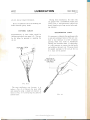
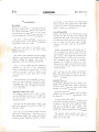
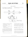
ENGINE AND FRAME NUMBERS
Both the engine and frame numbers, together with prefix and suffir letters, must be quoted in full on any
correspondence relating to the machine or on auy enquiry regarding this manual. to either the dealer or
the Service Department.
The engine number is stamped on the left-hand side ol the crankcase immediately belorv the cylinder
base. The frame number is stamped on the left-hand side of the front engine mounting 1ug.
ENGINE NUMBER
FRAME NUMBER
Page 7
www.bsaunitsingles.com
FACTORY SERVICE ARRANGEMENTS
(UNITED KINGDOM)
REPLACEMENT PARTS
ts.S.A. replacement parts and exchange units are distributed through a national network of B.S.A. clealers,
each of whom holds a stock of fast moving parts. Approxiniately 200 of these dealers have been selected
for appointment as specialist B.S.A. replacement part stockists and each of these stockists holds a comprehensive stock of B.S.A. replacement parts.
A complete list of appointed stockists is printed at the end of this manual, and also in every B.S.A.
parts catalogue.
REPAIRS
Most appointed B.S.A. dealers are able to carry out major repair work, and orvners are asked to make
all repair arrangemeltts through their chosen dealer.
In the great majority of cases local repair will be possible and this will avoid the expense, inconvenience
and the possibility of the macl-rine being damaged in transit to or from the works for repair.
Should your B.S.A. dealer decide that Service Department attention is required he will know best
how to make suitable arrangements with the factory. It is important to remember that no machine can
tre accepted at the works without a prior appointment. This appoir.rtment can be made either by letter
or by telephone.
GUARANTEE CLAIMS
hl the interests of all concerned it is best that ally owner of a new motor-cycle, wishing to claim
assistance
under the guarantee, should do so through the dealer from whom his machine was purchased. All B.S.A.
deaiers are familiar with the procedure designed by B.S.A. to give quick service to any owner of a B.S.A.
motor-cycle who may find himself in difficulty.
EXCHANGE REPLACEMENT SERVICE
We have operated for many years an exchange service for works re-conditionecl units including such items
as engines, front forks, frames, wheels, brake shoes and cylinder barrels.
These parts can,
if
necessary, be supplied through your B.S.A. dealer before the original parts are
returned? so reducing to a minimum the time that the machine is off the road. Details of the units available
under this scheme can be obtained on request from the Service Department.
Page
8
www.bsaunitsingles.com
fTECHNICAL ADVICE
B.S.A. Service Department staff are experienced in dealing u,ith technical problems ol all kinds and will
be pleased to l-relp in the event of difficulty. The correct address of the Service Department is as follows:-
B.S.A. MOTOR CYCLES LIMITED,
SERVICE DEPARTMENT.
ARMOURY ROAD.
BTRMINGI{AM 11.
Telcphont
No. \/lCtoria
2381
In all communications the model must be quoted with full engine
and frame numbers together with all prelix or suffix letters.
\YORLD SERVICE ARRANGEMENTS
In most markets of the world, B.S,A. has an appointed distributor to u'hom all
service enquiries should
be addressed.
The names of these distributols tvill be found at the back of this manual. and are also listed in ali
B.S.A. replacement part catalogues.
Page 9
www.bsaunitsingles.com
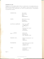
PROPRIETARY PARTS
Equipment not of our.manufacture which is fitted to our motor-cycles is of the highest quality and is
guaranteed by the manufacturers and not by us. Any complaints or repairs should be sent to the manul
facturer concerned or their accredited agents who will give every possible assistance. The following are
the manufacturers concerned
:-
CARBURETTER
Amal Limited,
Holdford Road,
Witton,
BIRMINGHAM
CHAINS
6.
Renold Chains Limited,
Wythenshawe,
MANCHESTER.
ELECTRICAL EQUIPMENT
Joseph Lucas Limited,
Gt. Hampton Street,
BIRMINGHAM 18.
Wipac Group Sales Limited,
London Road,
BUCKINGHAM.
REAR DAMPERS
Girling Limited,
Birmingham Road,
WEST BROMWICH, Staffs.
SPARKING PLUG
Champion Sparking Plug Co. Ltd.,
Feltham,
MIDDLESEX.
SPEEDOMETER
Smith's Motor Accessories Limited,
Cricklewood Works,
LONDON N.W.2.
TYRES
Page
Dunlop Company Limited,
Fort Dunlop,
BIRMINGHA}!I 24^
10
www.bsaunitsingles.com
T
t .1.,:
ti i1i1:;l
1
.
I{
U.S.A. SERVICE ARRANGEMENTS
ll^d.
,;:
; ,,!
'8..
l;
{-lc.l,;,."
,t1"r'cJnil€
q.!++!l
: . t7:'Luk}
,.-,, r,. '-.,..]
REPLACEMENT PARTS
,8..S.,4. replacenrent parts ore araileble tltrouglt
{Jnited States.
a National Nety,ork of' B.S.A. dealers cot,ering the entire
Tltese B.S.A. titotor^cNcle deolers are listed under "Motot'cycles"
in tlte velloit
poges af your local
telephone directory.
All recluests lbr parts mitst be made lhrctugh./'runchisecl 8.5.,4. cleo!ers, they nre not sold dit'ect to B.S.A.
ovners by the lv'o .fcrciory branches.
GUARANTEE CI,AIMS
In the interest o.f all concernecl the ov'ner o.l'ct new nlotor-(ycle wislting to cl(tint assistctttce under the guorcurtee
ntust do so through the deoler /ront y'ltom ltis tnocltitre vos prrrcltuseJ.
REPAIRS
B.S.A. clealers are capable of-senicirtg ancl repairing B.S.A. ruotor'-c1;slss, ask
),-oLtr deqler
to help v-hen
repnirs are needed.
Labotrr time u'ill be greatly reduced iJ' pro7trierury articles. such as legshields, r:raslt bars, carriers or
fbre glass fairings, or€ renlov-€d belore h.anding tlte nruchine over far repait'. Accessories such as mircors
or badges should alv'ays be retnot,ed beJbre entrusting a mttchine to
at1 independant
carrier.
TECHNICAL ADVICE
The B.S.A. Service Departntent slaff at the ttt'o Lf .S.A. foctorv brancJtes ttre erperienced
technical questions o/ ull kinds and v'ill be plecrsed to ltelp in tlrc event af difficulty.
The
factory brqnch
ctddresses qre shov,n
EASTERN
in dealirtg witlt
belov,'.B.S.A. INCORPORATED,
639 Passaic Avenue,
Nutley,
NEW JERSEY
WE,STERN
07110.
B.S.A. MOTORCYCLES-WESTE,RN,
2745 F.. Huntington Drive,
Duarte,
CALIFORNIA
9IO1O.
ln all communications the /ull engine and fi'ame numbers with all prefx and
nlust be quoted us y,ell qs tlle yectr cnd ntodel o{ the ntotor-cycle in question"
sffix
letters and .figures
Page
www.bsaunitsingles.com
11
WORLD DISTRIBUTORS
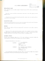
PREPARING THE MACHINE
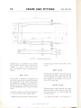
REMOVING THE MOTOR-CYCLE FROM THE CASE
Noru:-Check that the packing case is tlie RIGHT SIDE UP before dismantling. The TOP has stencilled
markings on it, the bottclm does not.
Prise off the top boards rvith a suitatrle pinch bar and take out the top packing material. Take off
one side of the case :rnd carefully withdrarv the machine. Make absolutely certain that you have all the
loose parts befbre discarding the wrappings and retain the TEST CARD in case you may'find it necessarl'
to report any loss ol parts or damage di-rring transit.
Put the machine on
the loosc components.
to its centre stand, place a strong sltpport urrder the engine and
proceecl
to fit
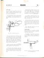
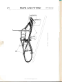
FITTING THE HANDLEBAR AND CONTROLS
Place the handlebar in position and fit the clamp brackets loosely. When a suitable position has been
cletermined. the fbur clanrp firing bolts can be tightened.
Fit the clr,rtch lever, exhaust valve lifter 1ever, lront brake lever and tlre thlottle control. but do not
tighten the fixing screws until they l.rave each been comfortably positioned on the handlebar.
Arry adjustments to the cor-rtrol cables can be made at a latel
sta_se.
FITTING THE FRONT MUDGUARD AND WHEEL
Place the front mudguard betrveen the
fork legs and assemble the stays. making sure that each r.rut and
in the spindle in an anti-clockwise direction, until
it is almost tight. Locate the brake plate anchor peg in the recess on the inside ol the right-hand fork leg
bolt is tightened secltrely. Fit the front
r'vheel and screw
and tighten the ri'heel spindle fully.
Depress the forks once or twice to enable the lelt-hand lork end to position itsell on the spindle before
finally tightening the pinch bolt. If this precairtion is r.rot observed, the tork leg may be ctippecl out of
position and will not function correctly.
Screrv the brake cable adjr-rster into the ri-eht-lrand fork leg bracket ancl connect the cable to the brake
lever toggie.
The machine support can now be removed lrom belou, the engine.
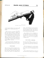
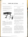
FITTING THE DUAL SEAT
First assemble the large bracket on to tl.re seat base plate. using the two r.ruts and washers. Note that the
bracket is correctly fitted when the more acutely angled portion is on the right-hand side.
Engage the clip below the dual seat at the front with the frame tie-bar. Loosen the damper top flxing
bolts sufficient to allow the ends of the seat bracket to locate over the bolts, directly behind the nuts. Whilst
pressing dorvn on the seat. tighten both fixin-e bolts firmly.
Page
12
www.bsaunitsingles.com
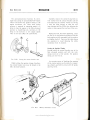
FITTING THE SILENCER
Fit the silencer on to the end ol the exhaust pipe and locate its fixing bracket behind the pillion footrest
bracket. Secure the brackets tosether at the rear by one nut and bolt and tighten the silencer end clip on
to the exhaust pipe.
Tl-re brackets are held at the
front bv the pillion footrest anchor bolt.
FITTING THE FOOTRESTS
The pillion footrests are pre-assembled to their anchor bolts and should each be secured to the brackets
by one nut with spring washer. The plain washers should be fitted betrveen the anchor bolt and its bracket.
Note that the right-hand footrest bolt also retains the siler-rcer bracket.
Fit the front footrests on to the fran-re lugs. On the right-hand side the firing is by one long bolt with
washers and a ltut. A special lockwasher, spring washer and a nut (left-hand thread) is used qn the lefthand side to secure the footrest on to its stud. Set both footrests to the desired height before tightening
the nuts.
SPARKING PLUG AND TOOLS
Take out and discard the plastic plug fron-r the sparking plu-e hole. fit the sparking plug and connect the
high-tension lead. The type of plug supplied with the machine is best suited to ail-rounci operatin-s conditions
and should not be changed without the advice of a plug specialist.
Place the tools. instruction manual and other literature
into the toolbox.
BATTERY
fhe battery is supplied in a dr-v charged conditior.r and must not be filled unless it is known that the machile
is to be sold within a few davs.
seen
Only half a turn is required to release the sidecover lasteners and on removal of the cover,
that the battery is secnrely mounted in a carrier alongside the toolbox.
it will
To FilI and Charge the Battery
A11 plates in the battery have been char-qed
fully and dried completely by special process. The tape across
the vent holes prevents the ingress of moistr-rre or air aud insures perfect condition ol the plates dgring
transportation and storage. This tape must only be removed immediately before the battery is brought
into service. Dilute sulphuric solution S.G. 1.260 can be prepared by slowly pouring 1 part of concentrated
sulphuric acid into 3 parts of distilled water (by voiume) or of S.G. 1.210 by adding I part olconcentrated
sulphuric acid to 4 parts of distilled water (by volume).
A
glass, earthenware or lead vessel should be used and the mixture well
stirred. Aiiow to cool to the
temperature of the surrounding atmosphere before using.
Il,tpoRraNr:-On dry charged batteries the filling of each cell with acid must be completed
operation and levels restored after standing by syphoning off excess acid"
in one
Pase
www.bsaunitsingles.com
13
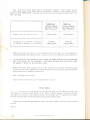
FILL EACH CELL WITH PURE DILUTE SULPHURIC ACID TO I,\ INCH ABOVE PLATE
PACK AT ONE OPERATION. The temperature of the acid and batterv should be between 60"F. and
80'F. (see chart).
TE.MPERATE
Climates ordinarily
below 80'F. (21'C.\
Specific gravity
lor filling
new cells
Specific gravity at completion
be adjusted if necessary, to
of charge to
be betrveen
TROPICAL
shade temperature
Climates frequently
above 80'F. (27"C.)
shade temperature
1.260 (at 60''F.)
1.210 (at 60'F.)
1.270 and
1.290 (at 60'F.)
1.210 and
1.230 (at 60'F.)
t.
Batteries r'vhich have been stored at a lo',ver temperature than 60'F. should have their temperatrires
raised before filling by allowing the battery to stand in a rvarm room until it attains room temperature.
2.
AFTER FILLING AND STAIIDING FOR I HOUR OR MORE SYPHON OFF AND DISCARD
ANY ACID FROM ANY CELL WHERE IT HAS RISEN HIGHER THAN THE PLATE PACK
TO BRING IT BACK TO PLATE PACK LEVEL.
3.
Batteries used under these conditions are up to 90i2" charged. but if time permits a lreshening charge
of 4 hours at the normal recharge rate would be beneficial. If the acid 1evel rises after this fresenhing
cl-rarge restore levels as directed in paragraph (2).
Nore
:
Recharge rate 0.8 ampere.
Keep acid juvt level rvith plate pack by adding distilled rvater onlr'.
FINAI- CIIECK
Before the mctor-cycle is put into service every nut, bolt and screw must be checked lor security and
correct fitting. It should be noted that 909u" of all vibration problems leading to missing nuts. fractures
and rattles. can be traced to loose engine mountings. l)o not simply take it for -sranted that the factor-"has done everythirrg right. take the precaution of checking everything yourself.
Eusure also. that suitable adjustments are made to the control cables and that each control functions
correctly.
Page
14
www.bsaunitsingles.com
STARTING THE MOTOR-CYCLE
Fill the oil tank. primari, drile and gearbox u'ith correct
-srades
of c.il
(see page
A.3). Pottr
some
petrol into the ta1k. turn ot1 the taps ancl srvitcl-i on the ignition. The ignition keys rvill be found in the
tool roll. Before starting the engine. nrake sure tl.rat tl"rere is no packir-rq material in or :rrorrnd the carburetter intake and air cleaner.
Whilst the engine is ru6nin-q. ral<e off the oil filler cap and check that the oii is circulating correctly
through the retLrrn pipe.
Havil-e established that all the controls have beeu suitably set for correct operation. the machine
rvill be complete and ready for
use.
Page
www.bsaunitsingles.com
15
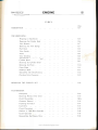
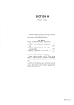
CONTENTS
Poge
Section
GENERAL DATA
GD
LUBRICATION
A
Ito12
ENGINE
B
Ito40
CARBURETTER
C
Ito8
FRAME AND FITTINGS
D
Ito13
FRONT FORKS
E
1to9
WHEELS, BRAKES AND TYRES
F
1to14
ELECTRICAL EQUIPMENT
G
1to16
TORQUE WRENCH SETTINGS
H
1
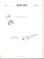
SERVICING TOOLS
J
1to8
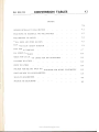
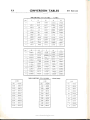
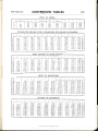
CONVERSION TABLES
K
1to9
Page
16
www.bsaunitsingles.com
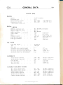
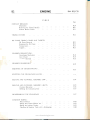
GENERAL DATA
844 B25tC25
I
GDI
INDEX
ts44
B2slczs
Page
Page
GD.4
GD.2
GD.2
GD.4
GD.4
GD.4
GD.3
GD.2
GD.2
GD.2
GD.3
GD.3
GD.3
GD.3
GD.3
GD.3
GD.8
GD.6
GD.6
GD.8
GD.7
GD.7
GD.7
GD.6
GD.6
GD.6
GD.7
GD.7
GD.6
GD.7
GD.7
GD.7
GD.5
GD.5
GD.5
GD.5
GD.9
GD.8
GD.9
GD.9
ENGINE:
Bearing Dimensions
Camshaft
Camshaft Bearing Bushes
Carburetter
Cylinder Barrel
C;.rlinder Head
lgnition Timing ...
Oil Pump ...
Piston
Piston Rings
Spark
Ph"rg
Tappet Clearance
Valves
Valve Guides
Valve Springs
Valve Timing
TRANSMISSION:
Chain Sizes
Clutch
Gear Ratios
Sprockets
FRAME AND FITTINGS:
Front Fork
Front Fork Bushes
GD.lO
GD.IO
Rear Dampers
Swinging Arm
GD.1O
GD.IO
WHEELS, BRAKES AND TYRES:
Brakes
Tyres
Wheels
GD.II
Wheel Bearings
GD.Il
GD.Il
GD,IO
ELECTRICAL EQUIPMENT
GD.l I
CAPACITIES
GD.11
BASIC DIMENSIONS
GD.12
WEIGHTS
GD.12
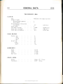
Because the engine and transmission of tlre B44 and the B25lC25 models
are of different specification, it has been found necessary to divide the
data into two sections, one for each model. A11 other data however, is
applicable
to both
models.
www.bsaunitsingles.com
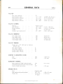
GENERAL DATA
GD2
844
ENGTNE (B44)
PISTON
Material ...
Compressiorr ratio
Clearance (bottom of skirt) ...
Clearance (top of skirt)
.003"-.0035"
006'-.0065"
(.0762-.0889 mm.)
(.0524-.1651 mm.)
(both nteasut'ed on majot a.rrs).
PISTON RINGS
Material-compression (top) ...
Material-cornpression (certtre)
Material-scraper
Width--compression (top and centre)
Width-scraper
Depth
Clearance
in
groove
Fitted gap-(maximum)
Fitted gap-(minimum)
orr,
Brico BSS.5004 (chrome-plated)
Brico 8
Brico BSS.5004
.062s'
.t25',
(1.5875 mm.)
(3.175 mm.)
.120'-.121'
(3.048-3.2258 mm.)
.001-.003"
(.02s4-.0762 mm.)
.014',
(.3556 mm.)
(.2283 mm.)
.009'
punnp
Zinc base alloy
Double gear
Pump body material
Type
Drive ratio
Non-retnrn valve spring (free length)
Non-retrirn valve spring ball (diameter)
Oil pressure release valve spring (free length)
Oil pressure release valve ball (diameter) ...
1:4
.3125"
(12.7 mm.)
(6.35 mm.)
(15.4781 mm.)
(7.9375 mm.)
.5598"-.5603"
(14.2189--14.23 1 6 mm.)
.1480',,, .1485',
(18.9992-19.0119 mm.)
(8.763 mm.)
(8.534 mm.)
(9.8044 mm.)
.5',
.25',
.6094',
CAMSTXAFT
Journal diameter (left-hand) ...
Journal diameter ( right-hand)
Cam lift (inlet)
Cam lift (exhaust)
Base circle radius
345',
336',
386',
CAMSHAFT BEARING BUSHES
Bore diameter (fitted) leflt-hand
Bore diauteter (fitted) right-hand
Outside diameter (left-hand) ...
.561',-.562',
.1492',-.1497',
.119',-.720',
Outside diameter (right-hand)
Camshaft clearance (left-hand)
Camshaft clearance (right-hand)
.908"-.909"
.0001'-.0022'
.0007'-.0017"
www.bsaunitsingles.com
(r4.2494-14.2748 mm.)
(19.A297
mm.)
-19.04238mm.)
(18.2626-18.2880
{23.0632-23.0886 mm.)
(.01778-.05588 mm.)
(.01778--.04318 mm.)
r
I
GENERAL DATA
B'44
GD3
\/AI,VES
Seat angle (inclusive) ...
FIead di:rrneter (inlet) .."
Head djanleier
(exl.raust)
90'
t
(i8.9890-39. 1 160 mn-r.)
(35.737-35.854 mm.)
.3090"--.3095"
(1.861 -1.814 nrm.)
(7.848 7.851 mnr.)
1.53,r"-
...
Stem diameter (inlet) ...
Stem diametcr (exlraust) ...
-1 .5,:10"
.4al'-1.412',
"3095"-.3 i00"
VALVE GUIDES
Pliospiror bronze
N4aterial ...
Bore diameter ...
.3120"--.31-r0"
Outside dianreter
.5C05"-.5010"
Length
1.859',
.00r 5"-.0025'
(7.9)48-7.950 mm.)
(12-7 l2l - 12.1254 mrn.)
(47.2186 nm.)
(.0381-.0635 r.nrn.)
Free length (inner)
Free length (outer)
Fitted length (inner)
1.500"
(38.10 mn.)
1.670',
Fitted length (orrter)
1.312'
(42.418 rnm.)
(30.9372 nrm.)
i33.3248 mm.)
Cylinder
VALVE SPRINGS
1.2t8',
VALVE TIMING
Tappets set fo .015" (.381 mm.) fcrr checking
purposes only:
Inlet opens B.T.D.C.
Inlet closes A.B.D.C.
51'
Exhaust opens B.B.D.C.
Exhaust closes A.T.D.C.
78'
68',
37',
TAPPET CLEARANCE (Cold)
Inlet
008'
Exhaust
"010"
(.2032 mm.)
(.254 mm.)
.lo)
(6.731 mm.)
29"
.015"
(.381 rnm.)
IGNITTON TIMING
Piston position (B.T.D.C.) fully advanced ...
Crankshaft position (8.T.D.C.) fully advanced
Conta-ct breaker gap setting ...
SPARK PLI.]G
Type
Champion N6Y
Gap setting (minim um/maxim um)
.020'--.025'
14 mm. dia. r
Thread
size
"75" reach
www.bsaunitsingles.com
(.508-.635 mm.)
(19.05 mm.)
GENERAL DATA
GD4
844
CYLINDER BARREL
Material "(standard)
Bore size
...
...
...
...
Stroke
Oversizes
Aluminium with austenrtrc iron liner
79 mm.
90 mm.
010' & .020" (.254 & .508 mm.)
CYLINDER HEAD
Aluminium alloy
Material ...
1.125'
1.25'
Inlet port size .,.
Exhaust port size
(28.575 mm.)
(31.75 mm.)
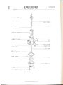
CARBURETTER
Type
Amal 930/ll (concentric float chamber)
Main jet
Pilot jet ...
25
Needle
jet
230
(2.7178 mm.)
.701'
size
Needle position
2
Throttle valve ...
Nominal choke size
Throttle slide return spring (fiee length) ...
J
30 mm.
2.5',
(63.5 mm.)
.1875" x.1875"
(4.7025x4.7025 mm.)
1.770t'-1.7706'
.250" dia. x.250"
(44.9605-44.9732 mm.)
(6.35 x 6.35 mm.)
(t9.0s16-19.0652 mm.)
(32.253-32.258 mm.)
BEARING DIMENSIONS
Clutch roller (25)
Con-rod big-end bush (bore)
Con-rod big-end roller (24) ...
Con-rod small-end bush (bore)
Crankpin diameter
Crankcase bearing (drive-side)
Crancase bearing (gear-side) ...
Flywheel shaft diameter (drive-side
and gear-side)
Gearbox layshaft bearings (drive-side
and gear-side)
.7503',-.7506',
1.2698',-1.2700',
25x62x 17 mm.
25x62x 17 mm.
984t',-.9844',
0.5" x.625"
(24.9961-25.0038 mm.)
x.8125' (12.1 x
15.875
x
20.6375 mm.)
Gearbox layshaft diameter (drive-side
and gear-side)
Gearbox mainshaft bearing (drive-side)
Gearbox mainshaft bearing (gear'-side)
Gearbox mainshaft diameter (drive-side)
Gearbox mainshaft diameter (gear-side)
Gearbox sleeve pinion (internal diameter) ...
Geabox sleeve pinion (external diameter) ...
Gudgeon pin diameter
.6245',-.625',
30x62x 16 mm.
.625" x1.5625" x
.4375'
.7485',-.749',
.6245',-.625',
.752',-.753',
1.179'-I.180'
750',-.7502',
www.bsaunitsingles.com
(15.8623-15.8750 mm.)
(15.875 x39.2875x
11.1125 mm.)
(19.0119-19.0246 mm.)
(15.8623-15.8750 mm.)
(19.1008-19.1262 mm.)
(29.9466-29.9720 mm.)
(19.05-19.055 mm.)
GENERAL DATA
844
GD5
TRANSMTSSTON (844)
CLUTCH
Type
Multi-plate rvith integral cush drive
Number of plates:
Driving (bonded segments)
Driven (plain)
Overall thickness of driving plate
and segments
Clutch springs ...
Free length of springs
Clutcli push rod (lerrgth)
Clr.itch push rod (diameter)
4
5
.t61',
(4.242 mm.)
4
1.65685"
(42.0687 mm.)
9.0'
(228.6 mm.)
.I
875"
(4.7025 mm.)
GEAR RATIOS
Cearbox-top...
-third
-second...
top
Overall-first
-third
-second
rst
-fi
r.0
I.24
1.65
2.65
5.14
6.39
8.45
t3.62
SPROCKETS
Engine
Clutch
Gearbox ...
Rear wheel
28 teeth
52 teeth
17 teeth
47 teeth
CHAIN SIZES
Primary...
Transmission
Duplex .315" >; 72 links
0.625' x 100 links
www.bsaunitsingles.com
GENERAL DATA
GD6
Bzs lcTs
ENGTNE (B2s/C2s)
PISTON
"Lo-Ex" aluminium
Material ...
Compressior, ,.uiio
Clearance (bottom of skitt)
Clearance (top ol skirt)
(Both meaiured on major axis)
PISTON
l0:1
0023"-.0028"
0042"-.0053"
(.05842. .011l2 mm.)
(.10668 .13462 mm.)
R.IF{GS
Material compression (toP) ...
Brico BSS.5004
Material-compression (centre)
Material-scraper
Width-compression (top and ccntre)
tsrico
Width-
scraper
in
.0tr25'
125',
Depth-compression
Depth-scraper
Clearance
8
Brico 8SS.5004
tl:.' "":.."n":l
groove
Fitted gap-(maximurn)
Fitted gap-(minimurrr)
1.5875 nim.)
(3.175 mm.)
(
001'
(2.1432-2.8956 mm.)
(2.3876-2.540 mrn.)
(.0254-.0162 mm.)
.009"
(.3302 mm.)
(.2283 mm.)
.108"
.094',
-.114'
-.100"
-.003"
.013"
OIL PUMP
Zinc base alloy
Doubie gear
Pump body material
Type
l:4
Drive ratio
Non-return vah'e spring (free length)
Non-t etttrn valve spring ball (diameter)
Oil pressure release valve spring (fi"ee length)
Oil pressure release valve ball (diameter) ...
.625',
.25',
.6094',
.3125',
(15.875 mm.)
(6.35 mm.)
(15.4781 mm.)
(7.9375 mm.)
CAMSHAFT
Journal diameter (right
Cam lift (inlet)
Cam lift (exhaust)
Base circle radius
&
left-hand)
.7480',-.1485',
345',
JJO
9A6',
(18.9992-19.0I19 mm.)
(8.763 mm.)
(8.534 mm.)
(23.0124 mm.)
CAMSHAFT BEARING BUSHES
Bore diameter (fitted)
Outside diameter
Camshaft clearance
7492',-.1491',
908"-.909"
.0007"-.0017'
(19.0291 19.04238 mm.)
(23.0632 23.0886 mm.)
(.01778 .04318 rnm.)
VALVES
Seat angle
Head
Head
Stem
Stem
(inclusive) ...
(inlet) ...
diameter
diameter
diameter
diameter
90"
t.450'-1.455"
(36.830-36.957 mm.)
(exhaust)
1.312',-1.311',
(33.3248-33.4518 mm.)
(inlet) ...
.3095"-.3100"
3090"-.3095"
(1.861-1.814 mm.)
(1.848-1.861 mm.)
(exhaust)
www.bsaunitsingles.com
Bzs
GENERAL DATA
lczs
GD7
VALVE GUIDES
Hidurel 5
3120"-.3130"
.5005"-.5010"
(79248-7.950 mm.)
Length
1.844',
(46.8376 mm.)
Cylinder head interference fit
.0015'-.0025"
(.0381-.0635 mm.)
1.400'
(35.56 mm.)
(44.45 mm.)
Material ...
Bore diamter
Outside diameter
(12.7127-12.7254 mm.\
VALYE SPRINGS
Free length (inner)
Free length (outer)
Fitted length (inner)
Fitted length (outer)
l.'750'
1.262',
1.370'
(32.0548 mm.)
(34.798 nm.)
VALVE TIMING
Tappets set to .015" (.381 mnr.) for checking
purposes only:
Inlet opens B.T.D.C.
5l'
Inlet closes A.B.D.C.
68'
Exl.raust opens B.B.D.C.
Exhaust closes A.T.D.C.
78
37
TAPPET CLEARANCE (Cold)
Inlet
008"
(.2032 mm.)
Erhaust
.010'
(.254 mm.)
.342',
(8.6868 mm.)
IGNITION TIMING
Piston position (B.T.D.C.) fully advanced ...
Crarikshalt position (8.T.D.C.) fully advanced
Cor,tact breaker gap setting ...
JI
.015"
(.381 mm.)
SP,A.RK PLUG
Champion N3
Type
Gap setting (minimum/maxim
Thread size
r
.020'-.025'
14 mm. dia. X
.75" reach
rm )
(.508 .635 mm.)
(19.05 mm.)
CYLINDtrR. tsARREI,
Material
Bore
size
(rtuniu.a)
Stroke
Oversizes
... ... ...
...
Aluminium with allstenitic iron liner
67 mm.
70 n*rm.
16 mm. and I mm.
CYLINDER HEAD
Aluminium alloy
Material ...
nlet port size . .
Exhaust port size
I
.
1.125'
1.25'
(28.575 mm.)
(31.75 mm.)
www.bsaunitsingles.com
(
ll
GENERAL DATA
GD8
825/C2s
CARBURETTER
Type
Amal 928/l (concentric float chamber)
Main jet
Pilot jet ...
220
25
Needle jet size ...
Needle position
.107'
Throttle valve ...
Nominal choke size
Throttle slide return spring (free length)
(2.7178 mm.)
3
28 mm.
2.5'
(63.5 mm.)
Clutch roller (25)
Con-rod big-end bearing-running cleararrce
Con-rod big-end-crank diameter
.187,5"r.1875"
.0005"-.0015"
Crank undersizes
.010".020'
(4.1025'x4.7025 ntm.)
(.0127--.0381 mrn.)
(36.5125-36.5252 mn-r.)
(.254, .508 &
.762 mn.)
(17.5006- 17.6108 mm.)
BEARING DIMENSIONS
Con-rod snrall-end bush (bore)
Crankcase bearing (drive-side)
Crankcase bearing (gear-side)
Crankshaft diameter (drive-side & gear-side)
Gearbox layshaft bearings (drive-side
and gear-side)
Gearbox layshaft diameter (drive-side
and gear-side)
Gearbox mainshaft bearing (drive-siCe)
Gearbox mainsl.raft bearing (gear-side)
1.4315'-1.4380'
.030"
&
.6890'-.6894'
25x62x 17 mm.
25x.62x 17 mnr.
.9841'-.9844'
\24.9961-25.0038 mm.)
.8125'
20.637-5 mm.)
.6245'-.625"
(15.8623--15.8750 mm.)
30x.62x 16 mm.
x
.4375"
Gearbox mairishaft diameter (drive-sicle)
.7485'-.749"
Gearbox mainshaft diameter (gear-side)
.6245'-.625"
Gearbox sleeve pinion (internal diarneter)... .752'--.753'
Gearbox sleeve pinion (external diameter)... 1.119'-1.180'
Gudgeon pin ciiameter ...
.6882"-.6885"
.625" x1.5625"
(15.875 x39.2875'x
11.1125 mn.)
(19.0119-19.0246 mm.i
(15.8623-15.8i50 mm.)
(19.1008-19.1262 mm.1
(29.9466--29.9720 mm.)
(17.4803-17.4879 mm.)
TRANSMTSSTON (B.2slC25\
CLUTCH
Multi-plate rvith integral cush drive
Type
Number
of
plates:
Driving (bonded segments)
Driven (plain)
Overall thickness of driving plate
and segments
Clutch springs ...
Free length of springs
Clutch pusl-r rod (length)
Clutch puslr rod (diameter) ...
4
.167'
(4.242 mm)
4
1.65685'
(42.0687 mm.)
9.0'
(228.6 mm.)
.1815'
www.bsaunitsingles.com
(4.7025
mm)
GENERAL DATA
ts2s/c2s
GEAR. RAT{OS
Gearbox--.top
1.0
1.24
--third
--second
i.65
--first
2.65
Overall--top
.
..
6.92
B.6l
1.40
18.36
1
SPROCKETS
Engine
CIutch
Gearbox...
Rear wheel
2-1 teeth
52 teeth
16 teeth
49 teeth
CHAIN SIZES
Primary...
Transmission
Duplex .375" .':.70 links
0.625':. 100 iinks
www.bsaunitsingles.com
GD9
GENERAL DATA
GD IO
844 B25lC2s
FRAME AND FITTINGS
FRONT FORKS
Coil-spring (hydraulically damped)
10.75"-10.875" (273.05-216.225mm.)
34 lb./in.
Type
Springs-free length
rate
-spflng of coils
-numberidentification
20!/)
Red/green
--colour
REAR DAMPERS
Type
Coil-spring (hydraulically damped)
Springs- free length
8.40'
--spflng rate
-colour
SWINGING ARM
(213.36 mm.)
100 lb./in.
identification
-..
Bush type
Creen/pink
Bonded rubber
|.250',--1.253',
1.241',-1.248',
Bush diamter'
Housin5r diameter
Interference fit ...
Spirrdle diameter
.002"-.006"
.810"-.8 r l'
(31.75-31.8262 mm.)
(31 .673-31.699 mm.)
(.0508-.1524 mm.)
(20.570 20.595 mm.)
FRONT FORK BUSHES
Outer diameter (top) ...
Outer diameter (bottom)
1.4150',-t.4155',
lnner diameter (top)
Inner diameter (bottom)
Working clearance (top)
Working cleiirance (bottom)
Length (top)
Length (bottom)
Shaft diameter ..
Sliding tube bore diameter
Damper tube bush (outer dian.reter)
Damper tube bush (inner diameter)
Damper tube br-rsh (length) ...
WHEELS, BRAKES
t.473',-1.474',
1.250',-t.251',
(31.465-31.477 mm.)
(31.414-31.439 mm.)
(31.750-31.755 mm.)
1.2485',-1.2495',
(31.71l-31.737 mm.)
.0005"
(.0127 mm.)
.002"-.003"
(.0508-.0762 mm.)
2.125',
1
(53.975 rnnr.)
(31.75 mm.)
(31.699- 31 .7246 ntm.)
(31.465-37 .515 mm.)
.339',-.340',
(15.6591-15.7099 mm.)
(8.6106-8.635 mm.)
.53125',
(13.4937 mm.)
t.25',
1.248', 1.249',
.415',-t.411',
.6t65',-.6185',
AND TVRES
WHEELS
Rim size and tvpe (front)
Rim size and type (rear)
wM2-18
wM2-18
Spoke sizes:
Front (long) 20
Front (short) 20
Rear (long) 20
Rear (short) 20
10 s.w.g. x.8.3125" (3.251 x 211.1375 mm.)
(3.251r 177.8 mm.)
l0 s.w.g. x 7"
10 s.w.g. y.1.4375" (3.251 x 188.9125 mm.)
l0
s.w.-e.
www.bsaunitsingles.com
x
7.375"
(3.251
r
I
87.325 mm.)
r
li
GENERAL DATA
844 Bzslczs
GDII
WHEEL BEARINGS
Front (leit and righrhand)
Rear (left and right-hand)
Rear brake drum
Spindle diameter (front)
Spirrdle diameter (rear, left-hand)
Spindle diameter (rear, right-liand) ...
.875"'< .5625" single seal
.875" x 2." :r .5625" single seal
.815" x.2"'x .5625" double seal
.874A'
"8745'
.8745'-.8150'
.685"--.586"
(22.199 22.212 mm.\
(22.212-22.225 nm.)
(11.399-11.424 mm.\
7',
(177.8 nim.)
1.t25',
(28.575 mm.)
(177.8 nrm.)
(28.575 mm.)
(3.9687 mm.)
BRAKES
Frorrt ldirmeter)
Front (rvidth)
Rear (diameter)
Rear (width)
Lining thickness (front anci rear)
Lining area, sq./in. (sq./cm.) front
-rear
7',
1.t25',
.r5625',
r5.48
r
-5.48
(99.84)
(99.84)
TYRES
Size (front)
Size (rear)
Pressure (front)
Pressure (rear)
3.25" ::. 18"
3.50" r 8"
(82.55 x 457.2 mm.)
(88.9 x 457.2 mm.)
16 p.s.i.
(1.125 Kg./sq.cm.)
l7
(1.
r
p.s.i.
i5
Kg../sq. cm.)
ELECTRICAL EQUIPMENT (12 volt)
Battery
Lucas PUZ5A
Coil
Lucas MA.l2
Lucas 54041073
I-ucas 54041045
Lucas RM.19
Contact breaker unit (B44 moclels)
Contact breaker unit (B2,s models)
Generator
Generator outpLlt
I I 5 rvatt
Horn
Rectifier
Zener Diode
Bulbs---headlamp (rnain)
(pilot)
-headlanrp
beam indicator
-main
--stop-tail lan,p
Lucas 6H
Lucas 2DS.506
Lucas ZD.ll5
50/40 rvatt
6 watt
2 watt
621 watt
CAPACITIES
Fuel tank
1.75 gallsl2.l25 U.S. (7.956 litres)
Oil tank...
4 pints/4.8
Gearbox...
Primary chaincase
0.5 pinti0.6
Front fork (each leg)
U.S.
U.S.
0.25 pint/0.3
0.34 pint/0.4
U.S.
U.S.
(2.273 litres)
(.264 litre)
t.142 litre)
(.1893 litre)
www.bsaunitsingles.com
I
GD I2
GENERAL DATA
844 Bzslczs
BASIC DIMENSIONS
Seat height
27',
32',
(134.62 cm.)
(210.82 cm.)
(68.58 cm.)
(81.28 cm.)
Ground clearance
Overall height ...
8"
(2432 cm)
42',
(106.68 cm.)
Wheelbase
53',
Overall length
Handlebar width
83"
WEIGHTS
n
t
Machine unladen
.:
Engine/gearbox unit (less carbr.rretter)
320 lbs.
(145 Ke.)
85 lbs.
(3e Kg.)
f,
www.bsaunitsingles.com
I
j
LUBRICATION
844 Bzslczs
TNDEX
Page
CONTACT BREAKER
A.9
CONTROL CABLES
A.t2
DISMANTLING AND REASSEMBLING THE OIL PUMP
A.8
ENGINE LUBRICATION DIAGRAM
4.4
FRONT FORK
A.11
GEARBOX LUBRICATION
A.9
LUBRICATION SYSTEM:
Changing Oil and Cleaning the Filters
Scavengc Non-Return Valve
Crankcase
Oil Pipe Union
OIL PRESSURE AND NON-RETURN VALVES;
Low Oil Pressure
A.5
A.5
A.6
Syphoning
4.7
4,7
Crankcase Breather
A.7
PRIMARY DRIVE
A.t0
REAR CHAIN
A.10
RECOMMENDED LUBRICANTS
A.3
ROUTINE LUBRICATION
4.2
SPEEDOMETER CABLE
A.t2
STEERING HEAD
A.11
WH]EL BEARINGS
A.11
www.bsaunitsingles.com
LUBRICATION
A7
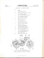
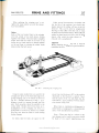
ROUTINE I,URRICATION
Re/. No"
Weekly
2.
12.
4.
Check oil level in tank.
Grease brake pedal pivot.
Oii exposed cables and ccltrtrol rod joints
Every 500 Miles (800 Km.)
10.
Check oil level ir.r primary chaincase.
2.
Every 2,000 Miles (3,200 Km.)
Drain and refill the oil tank.
9.
Check
2.
Clean tlie oil filters.
Examine pump bail valv--.
Grease centre stand.
Lubricate prop stand (oil).
11.
5.
l.
oil level in
gearbox.
Oil front brake cam spindle.
Grease rear brake cam spindle.
Lubricate rear chain.
Every 5,000 Miles (8,000 Km.)
6.
3.
3.
9.
10"
13.
Grease speedometer drive cable.
Lubricate contact breaker cam.
I-ubricate auto-advance mechanism.
Drain and refill gearbox.
DraLin and refill prirnary chaincase.
Every 10,000 Miles (16,000 Km.)
Drain and refill front forks.
Grease r'vheel bearings.
Grease steering head bearings.
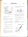
Ftc. A.1. Ke.y lubr icalion poittts.
(Numbers in circles refer to right side of machine;
numbers in squares refer to left side of machine).
www.bsaunitsingles.com
844 B75iC25
I
LUBRICATION
B'44 Bzslczs
A}
:l l.l
.j.t!.i
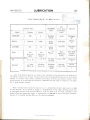
RECOMMENDED
ir'..
I,UBRICANTS
*'.-)
r',
il
:
,t"
x. ,. :^.
OIL
Front Forks
and Primary
ENGINE OILS
Winter
MOBILOlL
. : -'l'tli 1l r)
i:'")'r.r
,-- : 1"rA&".)
GREASE
Chain
Mobilube
GX.90
SHELL
CASTROL
Hypoy
90.EP
s.A.E.
Esso
Esso
Motor Oil
Motor Oil
purpose
20w/30
20/30w
Grease H
B.P. Gear
40
oil
REGENT
Havoline
Havoline
s.A.E.
s.A.E.
40
30
Esso Multi-
s.A.E. 20W
90.EP
Multigrade
Lubricant
Havoline
S.A,E,
2OW
90.EP
The choice of the lubricant grade is to a certairl extelit, dependent on the application ol the machine and
the clirrate in which it is to be used. The clrart above, gives recommended lubricarrts for use in temperate
climates. lu cottntries where climatic conditions are extreme, obi'iously some variation in grade will be
found necessary to provide adequate lubr:icatiorr. Remember that the higher the temperature" the higher
S.A.E. grade number required.
Nore :--During factory testing the engine is run on a mineral-base oil and a sirnilar type of oil must
be used thereafter. If it is desired tc change to a vegetable-base oil, the engine lubricating system must
be thoroughly cleansed of the previous lubricant. If the two types of oil are mixed, an emulsion wilt be
formed which may damage the engine. A vegetable-base oil must not be used in the primary chaincase.
because of the possible harmful effect5 on the electrical equipment.
www.bsaunitsingles.com
A4
:-:- tr
f.it::r
LUBRICATION
_.
tti
-z
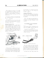
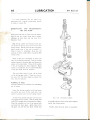
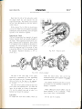
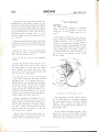
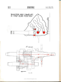
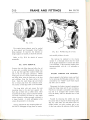
Frc. A.2. Engine lubricution
cliugrant slrowing the ball valves.
(844-bottom
www.bsaunitsingles.com
844 B25lC25
I
1-
LUBRICATION
844 BzslCTs
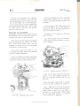
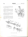
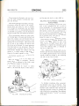
THE LUBRICATION
SYSTEM
The engine lr,rbrication system is of the d11
sump type, i.e., tl.,e oil is fed by gravity from
a tank to a double-gear pump situated in the
crankcase base at the right-hand side (see
Fig. A.2).
The top set ol gears in the pump draws oil
fronr the tanl< through a gauze filter and circulates it under pressure, past a pressLtre release
valve (D), a itorr-return valve (d) and tlrrough
the drilled crankshaft to the big-end bearing.
Excess oil is thrown off bv centrifugal folce.
on to the cylinder r.r'alls, the underside of the
piston (to lubricate tl.re gudgeon pin) and fills
various rvells to lubricate the camshalt and
A5
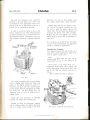
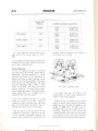
in peliod and thereafter as stated on page A.2-
It is always advisable to drain when the oil
is r'varm as it will flow more readily.
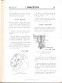
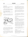
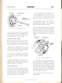
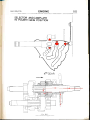
The oil tank filter is screwed into the lower
right-hand corner of the tank (see Fig. A.3).
Obtain a sr-ritable receptacle with a piece of
stiff material to use as a chute, unscrew the
filter (rvhich has a normal right-hand thread)
and allow the oil to drain. Wash the filter
thoror-rghly in petrol and allorv to dry.
BREATHER
gears.
After lubricating the various internal comoil drains down intc'r
ponents of the engine, the
the crankcase.
From here the lou'er. and larger set of pr-rmp
gears, draws oil lrom the gaLrze sump filten'
througli another non-retuln valve (C) and pumps
iL back to the tarrk at a greater rate tlian tl.rat
of the f-eed side. This ensi-rres that the sump
never floods hence the terni "clry sunrl-r."
The 'ril letr-rm pipe is tapped at the crankcase union to pro.ride a sr-rpoli of oil at 1o',r,
pressufe
to the',ah,e rocker
OIL FEED PIPE
Frc. A.3. Oil tonk ond filter.
gear.
On 844 models, this pipe is connected by
ol a twin union to the lefl-hand side of
the locker box. The 825/C25 models use a
Lean the machine towards the right-hand
to drain off any remainin-e oil in the tank.
means
side
common rocker oil supply, there being onlr
one oil pipe r-rr.rior.r at the rocker box.
the oil,
Tl^re
oil is led tlrrough the rocller shalts.
lubricating tlie r<lcker ball pins, adjLlster screws
and finally the tappets as it drains back into
the crankcase.
Again
r-rsir.rg
a
uuscre\\,
suitable receptacle to catch
the lour self-locking nuts
holding the sump filter to the crankcase and
remove the filter. A,lso disconnect the supply
artd scavenge pipes at the crankcase union
(one nut).
Allow the oil to drain, wash the filter thorough-
Changing the Cil and Cleaning the Filters
The oil in nerv or reconditioned engines should
be changed at 250, 500 and 1,000 mile (400.
800. 1,500 Km.) intervals durin-s the running-
ly in petrol, and clean off the old jointing
material lrcm the filter and crankcase. [f there
is any sign of darnage to the old gasket. replace
it or!
reirssembl).
www.bsaunitsingles.com
LUBRICATION
A6
Wlien refilling tl.re oil tank, do not exceed
the recommended level marked otr the filler
cap dipstick, as the air space above the oil is
esser-rtial for correct breathing. If the space is
reduced. oil is liable to be blown out of the
breather
tr-rbe.
To ensure an accurate oil level check therefore. the machine must be ot.t its centre stand,
not on the prop stand.
After starting the engirre, there rvill be some
delay before the oil is seen issuir.rg from the
retr-rrn pipe. This is because initially, the crankcase sunlp is clear of oil.
Scavenge Non-return Valve
Whilst ciranging lhe oil it is a good point to
check the scavenge pipe non-retttrn valve for
correct operzrtion. Using a piece of wire, pull
the ball up off its seating and allow it 1o drop
of its or.vn weight. If the ball will not drop
indicates a build-up of sludge rvhich can
usually be cleared by immersing the pipe in
petrol for a short period.
it
844 Bzslczs
thus allou'ing oil to run back lrom the tank.
Tl-ris is the valve jn the inner timing cover
describeC on page A.7.
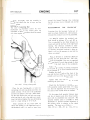
Oil Pipe Union
The oil pipe union is secured to the crankcase
with one nut. lf the small rubber sealing rings
in the oil pipe union are damaged, they must
be replaced.
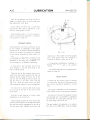
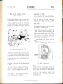
Crankcase
Norl: The oil pipes are correctly fitted rvhen
crossed over, i.e., the outer pipe from the tank
is attacl-red to the inner connection on the
crernkcase.
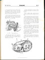
OIT, PRESSURE AND NON-RETURN
VALVES
A
constant oil pressure is maintained by the
release valve situa'red on the front right-hand
side of the crankcase (see Fig. ,4.6).
To prevent the oil pressure becoming excessive, the valve opens and releases the excess
oil direct into the crankcase lrom lvhere it is
returned to the tank.
CRCSS OVER
Ftc.
A.5.
Crankcase oil pipe uniort.
TI-re valve is pre-set at the works and there
is no point in altering the setting. However,
after prolonged use, the spring does tend to
Frc. A.4.
If there has been a tendency for the crankcase to filI with oil after standing overnight,
so causing the engine to emit clouds of smoke
when started, it is quite possible that the feed
line non-return valve is not seating properly
weaken and corrode and must then be replaced.
If there is corrosion it is wise to replace the
ball also, after first cleaning the valve body.
To
remove the valve, simply unscrew the
www.bsaunitsingles.com
LUBRICATION
844 B25tC25
I
A7
Indications of syphoning are clouds of smoke
from the exhaust when the engine is first started
alier standing overnight.
Frc.
Frc. A.6.
large hexagon plug. Ensure that the fibre
fit fbr further use.
A.7.
Nott-returtt yalt'e.
The feed line non-return valve consists ol a.
ball and spring and is located in the inner
timing cover (see Fig. A.7). After unscrewing
tlre retaining pir-rg, the valve spring and ball
can l-.e removed for examination.
washer is
Should there be any doubt erbout the condi-
Low Oil Pressure
l-ow oil pl'essLlre is dangelous since insulficient
oil is likely to be delivered to the engine components. The possible caLlses of low ilressllre
being:
l.
Ir-rsufficient oil in the tank. Clieck tlie
level and the return alter replenishing. If
the retirrn is correct it rvill show as a
mixture of oil and air issi-ring fionr tlte
tion of the valve
components rene$'
then-I,
sinee llrey are qLriic inexpensive.
The non-return valve in the
is described on page A.5.
scaver-rge pipe
Crankcase Breather
The shcrt crankcase hreatlter pipe emerges
fiom tl.re timing case llear to the ciutch cable
abutment.
return pipe.
2. Tank and sump filters partly
preventing the lree passa-qe
3.
Badly worn oil pump
need ol attention.
blocked,
of oil.
or big-end
tsREATH ER PIPE
bearing
in
4. Oil pipes incorrectly
connected. u'hen the
pump wor-rld be inducing air thlough the
return pipe.
Syphoning
This, one of the more common troubles, happens
when one of the non-return ball valves is
sticking off its seating. [t can also be caused
by a badly worn pump or one rvhich is loose
on its mounting.
www.bsaunitsingles.com
Frc. A.8.
LUBRICATION
A8
It is most
844 B75tC75
I
important that tliis pipe is una regular examination siror-rld
obstructed and
[-.e m:rde
to ensure thi-.
DISMANTI,ING AND REASSEMfiI-ING
THE OIL PUMP
Having removed the oil pump from the engine.
out the four screws from base of pump.
releasing the base plate :rnd top cover frour
tarke
the pump body.
The driving spindle and driving worm gear
ale secured to the top cover with one nut and
spring washer. Before removing the worm gear.
make careful note ,-lf the rvay in which it is
htted to assist in rebuilding. Note also tlie
position of tllrust washers below top gears (B44
models only).
Wash all the piirts thoroughly in petrol and
allow to dry before examining. Look for foreign
lnatter jammed in the gear teeth and deep score
marks in the pump body. These will be evident
il the rril changing has been neglected. Sliglit
marks can be igrrored, br-rt ar.ry metal embedded
in the gear teeth must be removed.
The most likely point of wear will be foLrnd
on the driving gear teeth; if these are worn to
the extent that the sharp edges have gone then
tl.rcy must be renewed.
Rebuilding fhe Furnp
Absolute cleanliricss is essential when rebuilding
the
oil
a '\\\
,",ll\\{\r
lr o
plrmp.
CD
jj I
\
Insert the driving spindle (with fired gear)
into pump top cover. fit the worm drive and
secure in position with nut and spring washer.
Fit the driven spindle and gear into the cover
and replace thrust washers. The oil pr-rmp used
onB25lC25 models does not have thrust washers.
top of the pump body
and insert tl.re lower gears. Apply clean oil to
the gears and refit the base plate. Check that
Place the assembly on
trtc. A.9. Oil pump
exploded.
the spindle and gears rotate easily before tighten-
ing the four fixing
screws.
Finally, check the joint faces for paralleiity;
www.bsaunitsingles.com
--
LI.'BRICATION
844 tszslczs
if the housing
face
is not level, it will
be
distorted when bolted to the crankcase and may
prevent the pump from working.
A9
The pivot points ol the auto-advance unit
should be lightly oiled, again at 5,000 mile
(8,000 Km.) intervals.
After lubricating, leplace the plate to the
if the timing has been upset, follow
CONTACT BR.EAKER
marks, buf
the instruciiolls on pages B.3B-40.
The cor-ltact breaker is sitr-rated on the outer
timing cover and it is essential that no engine
oil gets into the contact breaker housing. To
prevent this, there is an oil seal pressed into
the inner timing co.rer behind the auto-advance
unit.
Lubrication cf tlie contact breaker cam and
the auto-advance unit pivot points, however, is
GEARBOX LUBRICATION
The gearbox, having its own oilbath, is inclependent of the engine for lubric;Ltion but, for
the same reason, the oil le.,rel rnust be checked
and any loss clue to leakage n,ade good.
necessary.
The conta.ct breaker cam is lubricated from
an oil-soaked felt r,vick which sliould hai,e a
few drops of engine oil (S.A.E. 20 or 30) applied
every 5,000 miles (8,000 Km.) see Fig. A.10.
To lubricate the auto-advance unit it is necessary to remove the contact breal<er plate. First
mark across the plate and the housing so that
it can be replaced in exactly the same position.
Take out the fixing screws and rvithdraw the
contact tireaker piate.
DRAIN PLUG
LEVEL SCREW
FELT
WICK
Fic. A.l l.
as
Gearbox oil let'el systenl
on earlier modttls.
used
The iayshaft gears run in the oilbath and
oil being carried by or tlirown off these gears
lubricates the mainshaft gears, bearings and
bushes.
To drain the gearbox, take out the filler plug
on top ol the gearbox then unscrew and take
out the larger of the two plugs underneath,
draining the oil into a suitable r:eceptacle (see
Fig. A.11).
Frc. A.10. Contact breaker.
After draining, replace the drain plug, making
sure that the rubber "O" ring is in good condi
tion, but leave out the smaller plug.
www.bsaunitsingles.com
[-
Al0
LUBRICATION
Now filI the gearbox with fiesh oil until it
begins to overflol down the drairt plug tube,
then repiace the small plug.
844 B25tC25
l
&
Later models are fi1ted ivith a plain drain
plug arrd the filler plug is replaced by a dipstick for checking the oil level.
Recommended grades
ol oil
page A.3, capacities or1 page
are quoted on
GD.i1 and check-
ing frequency on page A.2.
@
PRIMARY DRIVE
Like the gearbox, ihe primary chaincase, having
its own oilbath, is independent of the
T
engine
c
but the level of oil nrust be checked periodically
and the oil drained and replaced as indicated
in the routine maintainance sheet, page 4.2.
Ftc. A.12.
inspection cap. The machine should be upright
The oilbafh in the primary chaincase does
not li-rbricate the chain only, the clutch being
corrtained in the same case is dependent on
this oil supply for its efficient functioning.
A drip feed is also provicled for the rear
clrain through an oil well and nozzle at the
back of the chaincase.
ol the chaincase cover screws
their heads painted red; they are
situated midway along the loi.ver rim of the
case, the rear one being the oil level screw (C)
and the front is the drain screw (D)--see
Fig. A.12. Note that these screws are fitted
rvith aluminium rvashers to ensure oil-tightness.
and on level ground when this operation
carried out to ensure correct level of oil.
is
Oil containing molydbenum disulphide or
graphite must not he used in the primary
chaincase.
When retrllenishing ,use only the grades recommended on page A.3.
There are two
r.vhich have
REAR CHAIN
Oil thrown off the primary chain is collected
in a small rve1l at the back ol the primary case
from which a drip feed is supplied to the rear
chain.
To drain the oil, take out th.e chain inspection cap (A) at the top of the case and tl-re
drain screw.
This supply is dependent on the maintenance
of the correct oil level in the primary chaincase.
Cap (B) is only removed to enable clutch
adiustments to be carried out.
This may not, however, be adequate in some
circumstances and it is advisable to supplement
After drainirrg, replace the drain screw, take
out level screw and pour oil through the inspection cap hole until it commences to run out of
the level screw hole. Replace level screw and
The best method of lubrication is to remove
the chain every 2,000 miles, wash thoroughly
the drip feed by cccasionally applying oil to
the chain links with an oil can.
www.bsaunitsingles.com
Att
LUBRICATION
844 B25 C25
in parallin and allow tcl drziin. tlien immerse
it in melted tallorv to which porvdered gral-rl.rite
in
has been added.
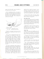
Oil leakage nrid."vay up the tbrks usuallr
indicates that an oil seal has failed and requires
replacement: this is dealt rvith on page E.-l
covering the disrnantling and r-eassembly ol the
Hang the cl.trin over the glease tin to alltrti
the surplus qrease to drain o1l. lf the tin is
covered atler use it can be used many times.
but alu,ays Llse care when meltin-c the tallou.
ezrcl.r
ibrk
leg.
is exactly the
same.
lorks.
When replacing the cl.rain. make sure thirt
the spring clip ol the connecting link has rrs
closed enC pointing in the clirection ol tr:rvel
of the chain (i.e.. forwards or.r the top rlllt).
Correct period for chaing the oil as quoted
on page A.2 is evet'y i0,000 miles (16,000 Kni.i
but some owners may not cover this mileage
in a year. in rvhich case it is sLrggested that the
oil be changed every 12 ntonths.
STEERING HEAD
To drain the oil" unscre\\/ tlre fork c.rp nuts
irrrd the small drain plugs in the lorver ends o1'
The steering l-read bea,rings are packecl rvith
greilse on assembll'
ald oliy
reqr,rile repackin,u
at the intervals qr"roted {)n page A.2. Rer.no',,ill
and leplacement ol the steering is clealt uirl.r
or1 pages E.2 and E.3 in the fork section.
the fork slidirrg members. Allow the oil ttr
dr:rin out then. whilst standing astride the
machine, apply the front brake aud slttivll
depress the forks a f-ew tirnes to clrain any oil
lenrainin-q in the systern.
Replace the drain plugs. r':rise the cap nuts.
t'ew inches and pour l,', pint of oil into eaclr
tork leg (see page A.3 for recomnrended grades
Wipe or,rt all the old grease fror-n the belrl'ing cups ancl clean the ball bearings. bv roliing
them in a clean rag.
I
Alter cleaning" carehrlly examine the bearings.
cups and cones 1or pitting. etrrrosion r'r' crucks.
and reneu, il rrecessarv.
Ensure that the rubber sealing u,asher lnd
special retzriner are correctlv fitteci belorv the
clamper rod locknr-rt befbre replacing the capr.
ol oil).
nuts.
The fiesh grease will hold the b:rll bearings
in position during leassemblr,. ChecL that the
is as t1r-roted on page A.3.
-qrea,se
There are sever:rl methods lor determining
the correct number of ball beariugs to Ltse. but
the rnost efl'ective method is to fill the cup
completely rvith ball bearings and then extrilct
one. The correct number ol ball bearirrcs 1br:
each cr-rp is trienty.
FRONT FORK
The oil contained in tl're lork legs not onll
lr"rbricates tl-re bearin-s bushes. br-rt also acts its
the damping medii-rm. Because of the latten
fr.rnction. it is essential tliat the amount ol oil
\THEEL BEARINGS
The wheel bearings are packed r,r'ith srease on
assembly ancl only require repacking at liteintervals given on page A.2.
The bearings shor-rld be removed as quoted
t)n page F.4. F.5 and F.6. After removal. the
bearings must be wzrshed thoroughly in paraffin
.rnd. if possible, an air line should be used tc'
blow out any remair.ring grit or paralfin.
Pack with correct grade ol -qrease as quoted
on page A.3 after assembiing the first bearing.
The rear brake drum be:rring. having ir double
www.bsaunitsingles.com
LUBRICATION
At2
oil
seal, does
not require lubrication.
Do not over-lubricate and avoid handling
brake shoes with greasy hands.
tlee
844 B25iC25
During their manufacture. the inner cables
are greased with a molybdenum based grease
which forms a semi-permanent lubricant and
should therefore give long service before needing attention.
CONTROL CABLES
SPEEDOMETER CABLE
Exposed sections
of inner cables should
be
lubricated periodically (see page A.2). This can
be done either by greasing or applying
oil
the
can.
It is necessary to lubricate the speedometer cable
to prevent premature failure of the innet wire"
Care is also necessary to avoid over-zealous
greasing which may result in the lubricant
entering the instrument head. For lubricating,
it is only necessary to unscrew the cable lerrule
and withdraw the inner wire. The grease should
be applied sparingly to the wire and the top
6 in. must not be greased.
THE TOP 6"
MUST NOT BE
CREASED
Frc. A.13.
The most satislactory way, however. is to
induce a flow of oil betweeri the inner cable
and casing by using a simple oil reservoir as
shorvn
in Fig. A.13 and leaving the cable'lor
Frc. A.1-t
several hours.
www.bsaunitsingles.com
ENGINE
B44 B25iC25
BI
INDEX
Page
DESCRIPTION
8.5
DECARBONISING
Preparing
to
Decarbonrse
B.6
Removing the C;rlinder Head
8.6
Valve Rockers
Removing the Valve Springs
8.7
8,1
Push Rods
8.8
Valve Cuides ...
B.8
Vllves
B.8
Valve Grinding
8.8
Reassembling the Cylinder Head
Cylinder Barrel
Removing the Cylinder Barrel
Removing the Piston ...
Piston Rings
Small-End Bush
Reassembly after Decarbonising
Checking Valve Cleararlces ...
REMOVING THE Etr-GINE UNIT
B.9
8.9
B.
t0
B.l0
B.tI
B.l1
B.l2
B.t3
B.l4
TRANSMISSION:
Description
ts.16
Removing Primary Drive Cover
B.i6
CltLtch Dismantling
B. I6
Generator Removal
ts.16
lnspecting the Clutch
B.l7
Cush Drive
B. t7
Clutch Chainwheel
Gearbox or Final Drive Sprocket
Clutch Operation
Reassemblins the Primary Drive
www.bsaunitsingles.com
B.
t8
B"
t8
B.1S
B.IE
ENGINE
82
844 B2.slC25
INDEX
Page
CONTACT BREAKER:
B.2A
Description
Removing the Contact Breaker
Contact Breaker Points
B.2l
B.2t
TIMING COVERS
8.22
OIL PUMP, TIMING GEARS AND TAPPETS:
Oil Pump Removal
Replacing the Oil Pump
8.23
Timing Gears ...
Tappets...
823
8.23
8.23
GEARBOX DISMANTLING:
il
8.24
8.25
8.25
Gearchange Mechanism
Gear Cluster ...
Gearbox Bearings
i
GEARBOX REASSEMBLY
8.25
SEQUENCE OF GEARCHANGING ...
8.27
SPLITTING -THE CRANKCASE HALVES ...
8.34
BIG-END AND FLYWHEEL ASSEMBLY (844)
8.34
BrG-END AND FLYWHEEL ASSEMBLY (Bzslczs)
Flywheel Balancing
Refitting the Connecting Rod
8.36
8.37
REASSEMBLING THE CRANKCASE
8.37
8.35
IGNITION TIMING:
Piston Position
Setting the Contact Breaker Cam ...
Setting the Ignition Timing ...
Checking the Ignition Timing with
a Stroboscope
www.bsaunitsingles.com
8.38
8.38
8.39
8.40
844 B25 C25
ENGINE
B3
t;
,&*,
,,r
p
,r
*x"{
o@
*@
q
\,e
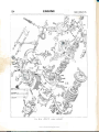
Ftc. B"l.q. 844 engine
exploded.
www.bsaunitsingles.com
B4
ENGINE
()
/K)
\J
e
@
www.bsaunitsingles.com
B'44 B25tC25
I
pp \'4@
ffi'.u-
844 B75lczs
ENGI N E
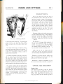
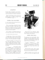
DESCRIPTION
B44 Models
The B44 o.h.v. four-stroke engine is of the
r-rnit
constructior.r type. having a sin_qle cylinder barrel
incorporating an austenitic iron liner.
"Lo-Er" aluminir-rm piston l'raving
(chronre-plated ) compressioir ring,
one tapered compression ring. arrci a scraper
A
B5
Pouer fi-oil the eugine is transmitted tlirough
the engine sprocket and dLrplex prii.nary chain
to the clutch assembly lvhich has a built-in
cLrsh drive. I{ere the drive i" taken up by the
bonded friction plates :rrrd is transmitted through
the four-speed constant-nresh gearbor to the
final drive sprocket.
special
one plain
B25iC25 Models
ring is used ou a H-sectiori conrrecting rod.
employing a roller be:rring big-end assembly.
Although being ol sr..raller ca1iacit1,. the B25/C25
engine bears ler],, sinrilar con.,tructional detail
to that ol the 844 model. The most noticeable
differences are in the valve rockcr gear and the
crankslraft asserrbll'. Each of the valve rocker
slrindles have an eccentric cam which provides
rl ffrearls of adjusting the rralr'e clearances.
Tu'o bal:tnced flylvheels (ri'itl"r crankshalts)
and the crankpin are held together by trvo large
nuts. the unit revolving on t\\,o crankcase
bearings.
The alr-nninir-rm alloy cylinder head has cast-irr,
heavy duty cast-iron valve seats and removabie
valve gr-rides. Hor-rsed u.ithin the iop of the
cy'linder head are two valve rocl<er spindles"
carrying the inlet rocker at the rear and the
exhaust rockel at the fiont.
The one-piece, high perfbrmance camshaft
operates in two bushes. one of phosphor brouze
and the cther of siutered bronze.
Contained within the prin.rary drive case oir
the left-hand hall ol the craukcase are
the
clutch assembly, primary chain and the alter-
nator. The alternator unit consists ol ern errcapsulatecl si>r-coil statol', nrounted on three
studs anrl a rotor. secured to the drive-side
sl.ial't.
A vertically mounted oil pirmp of rhe double
gear type is driver-r off a wormrvheel on the
-gear-side crankshaf-t and supplies oil to tlie
big-end assen.rbly" piston, cylinder u,ails and
the timing
gears.
Four special bolts hold each of the two flyu'heels to the one-piece forged crankshaft.
Incorporated in the right-hand flywheel is a
centrifu-eal oil sludge trap. fitted rvith a screwed
plrrg. Tlie bolt-on connecting rod big-end
assenrbll' consists of two bearing shell halves,
available in three undersizcs for use ri,ith re-
groLrnd crankshafts.
DECARBONISING
Decarbonising or "top overliaul" as it is sometimes called. means the removal of carbon
deposits flom the combristion chamber. 1-riston
cro\.vu. lalve heads aud iLrlet and exhaust ports,
and to restore a smootl.r firrish to these surfaces.
Obrviouslv. *'hilst the upper portion of the
en-uine is dismantled 1br this purpose, opportunity u,ill be taken to ex:Lmine the valves,
valve seats, splings. guides, etc, for general
"rvear ancl tear", henc: the terni "top overhaul.
"
Carbon. prodrrced by combustion taking piace
in the engine rvhen rur.rnirrg. is not harmful
The -qearbox. at the re:rr ol the right-hantl
hall of the crankcase, and tl.re primary chaincase are indetrrendent of the engine lubricatiorr
providirrg it is not allc,lved to become too heavy
ar-rd therefore likely to ca use pi-e-ign ition or
otl.rer symptoms wl.rich may impair the engine
system and each contair.r tl.reir own oilbath.
1-rerlorrnlrnce.
www.bsaunitsingles.com
ENGINE
B6
The r-rsual symptoms indicating tl.re need for
decarbonising, are an increased tendencl, f91
the engine to "pink" (metallic knocking sound
wheu under load), a general decrease in porver
and a tendency lor the engine to run hotter'
844 B75lC25
cirble has fir'st been extracted throLrgh the slot
in the end ol the operatiir-q
lever.
than r,Lsual. An increase in petrol consumptiol"l
nrav also be apparent.
Preparing to f)ecarbonise
Before commencir.rg with the r,vork. it is advisable
to have the lolloiving equiprnent available:-
lor f in. W. 1/+ in. B.S.F.
5. in. W., rr- in. B.S.F.
Spanners
of scrapers.
of feeler gauges.
Supply of fine grade emer_y cloth.
Jointing compound or cement.
Valve grinding tool No. 61 5035
to
Set
Set
and
coarse/fir.re grade grindin-q paste.
Valve spring compressor No. 6i-3340.
Clear.r engine oil.
Pieces of hzrrd rvooci
to support piston.
Top overhaul gasket set:No. 00 3163 (B44);
No. C0- 316s (8251C25).
Gudgeon pin circlips (2):-No. 66-954 (B44);
No. 40 919 (8251C25).
Valve springs (set):-
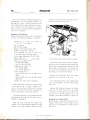
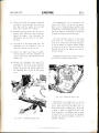
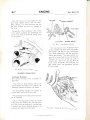
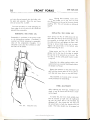
FIc;.
8.2. Removing e.rhaust
t'alr,e
li/ter assenrbly.
The exhaust pipe is a push-fit into the cylinder
head and can be withdrarvn after loosening the
finned collar and releasir.rg its bracket from the
front engir.re mounting bolt. The silencer clip
of course. mr-rst be slackened off br-r'i it rvill not
be necessarl'to detach the silencer.
Nos. 65-2494 (outer) &. 65-2195 (inner)
(B44);
Nos. 40-1008 (outer)
&
40-1007 (inner)
Remove the carburetter tl-om the cylir-rder
it back out of the war'.
head ancl tie
(B2slc2s).
Parafffin and clean ras
for
cleanins.
The oil leed pipe to the rocker spindles shoulcl
now be disconnected and tlie sparking plug
Perfect cleanliness is essential to ensure success
t:Lken out.
in any service task, so before starting a jotr
such as this, make sure that you have a clean
berich or rvorking area on r,rhich to operate anci.
roon to place parts as they are removed.
To facilitate lemoval ol the cylinder head fon
decarbonising, first take off the petrol tank. as
detailed on page B.14.
With the tank removed, the
engine stay
bracket can be disconnected. together rvith the
exhaust valye
lifter assembly. alter the inner
Because the clearance between the cylinder
head and the frame top tube is very limited,
it will also be necessary to take off the horn
and the coil to provide greater access. Note
carefully, the terminal location of each cable.
Removing the Cylinder Head
Set the piston at top dead ceutre on the compression stroke (both valves ciosed) and take
off the six nnts holding the cylinder head to
the barrel.
www.bsaunitsingles.com
T_
s44 tszslczs
ENGI N E
Leave the rocker box assembly in position
on the cylinder head, and raise the latter until
it clears its fixing studs. It will then be necessary to rotate the cylinder head assembly about
the push rods so as to clear the frame top tube.
The rocker box can now be removed fiom the
cylinder Iread, thus erposing the valves and
springs.
87
Refer
to trig. B.4 when
reassembling.
ll'
-t*
o
B44 Models
The clearance betr,veen the cylinder head and
frame top tube on these models is not sufficier-rt
to allow the head to be lifted off, rnaking it
necessary to take the engine out of the frame.
An alternative method is to extract the five
central rocker box studs to allow the rocker
box to be removed, so providing the necessary
clearance for cylinder head removal. Continr-ral
extraction of these studs however, will eventually
impair the threads irr tl-re head and it is preferable to remove the cornplete engine.
825 C2s
^s0
NJ
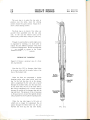
Frc. B.4,t.
Valve roc'ker assembly (844).
844
Frc. B.4e. Vafi,e
roc.ket. as,sembll, @251C25).
fitted to models
mede on and ufter engine No. C25-2050).
{The spring y'aslters y'ere not
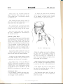
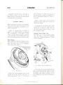
Ftc. B.3. lVorn
valve rockers.
Valve Rockers
Figure B.3 shows rocker arms rvhich have been
subjected to a great deal of wear, making the
correct valve clearances diflicult to determine.
During their manufacture the pads (B25/C25)
and the pins (B44) are case-hardened and no
attempt should be made to grind them smooth.
Il wear of this nature is apparent therefore,
replacement parts should be fitted.
R.emoving the Valve Springs
If the rockers and spindles are dismantled
take care to renew any damaged washers. On
B44 rocker spirrdles, see that the rubber sealing
rings are in good condition.
The .springs may have settled through long
use and they should therefore be checked in
accordance with the dimensions quoted on
pages GD.3 and GD.7.
Using service tool No. 6l-3340 or similar valve
spring compressor, compress each spring until
the sp)it collets can be removed. The valve
springs and top collars can now be lifted from
the valve stems, swilled in paraffin, then placed
on a nu.mbered board to indicate their position
in the cylinder head.
www.bsaunitsingles.com
l;
il
ENGINE
B8
If the springs have settled appreciably, or
there are signs of cracking. they shorild be
r eplaced.
Push Rods
Examine the push rod end cllps
to see if thel'
are chipped, worn or loose, and check thatt
the rods are not bent by rolling them on a
flat surface (i.e., a piece of plate glass). If any
of these faults are evident the rod(s) shoulcl be
844 Bzstczs
tool No. 6l 3300 r"rsed rvith pilot No.
6l-3293 and holder No. 61-3290. The seat
angle is 45 degrees.
seat cutter
Sometimes when the engine has been decarbonised many times, valves become "pocketed".
This is when tl.re valve head and seat are beio*'
the surface of the combustion chamber. so
impairing the efficiency of the valve and affect-
ing the gas flow. The "pocket" should be
removed with a special 30" angle cutter before
re-cutting the seat or grinding-in the valve.
renewed.
Valve Gurides
Check the valves in the guides; there sl, ould
be no excessive side-play or evidence of carbon
build-Lrp on that portion of the stem wl.rich
operates in the guide. Carbon deposits can be
removed by careful scraping and very light use
of fine grade emery cloth. If there are signs of
scoring on the valve stems, indicating seizure.
both valve and guide should be renewed.
An old valve guide can be driven out rvith
tool No. 61 3382 br-Lt. the aluminium
head should first be heated by immersir-rg in
hot water. The ner,v guide can be driven in
with the same punch whilst the head is stili
service
warm. Note that the exhaust guide is counterbored at the end which protrr-rdes into tl.re port.
tused
on laler
.
t',/,/.1
'l ,':'.//t
./
',/
Whenever ner'v guides have been fitted, each
valve seat must be refaced with a piloted valve
seat clltter, to ensure that the seal is coucentric
with the guide bore.
Nore :-Earlier B44 engines were fitted rvith
special valve guides, having a fixed valve spring
cup. These guides, and the cylinder head they'
are fitted irr, cannot be interchanged with those
.
. ///,/'1.',/..,.
VALVE POCKETED
SHADED ARE^
METAL TO BE REMOVED
Frc;.
B.5.
..
,//.//'/
Pocketed ralve
Valve Grinding
If the valves hzrve been renerved or relaced
they rnust be liglitly -srourrd-in to their seats
to eusLire a good gas-seal.
engines.
This operatiorr is carried out only alter ail
carbon deposits have been removed fiom the
Valves
Valve heads can be relaced on a valve relacer
but if pitting is deep or the valve head is burnt.
then a new valve must be fitted and ground-in.
The valve seats in the cylinder head are
unlikely to require any attention, but if they
are marked. they should be refaced with valve
combustion chamber.
Removal of carbon from the head. inlet and
erhaust ports can be carried out rvith scrapers
or rotary files, but wl-richever method is used
great care must be taken to avoid scoring the
valve seats.
www.bsaunitsingles.com
ENGINE
844 Bzslczs
A final "polish" can be achieved with the
use
of fine emery cloth rvetted by paraffin.
Do not attempt to decarbonise the cylinder
head by immersing it in caustic soda solutior-r;
the solution has a harmfLrl elJ'ect on aluminiunr.
Having removed all traces ol carbon, smear
a small quirntity ol fine grinding paste over the
lace of the valve and return the valve to its
seaf,
Now, using service tool No. 6l-5035, rotate
the valve backrvards and lorwards, maintaining
steady pressure. Every ferv strokes, raise the
valve and tnrrr it to a new pcisition. A light
spring inserted under the valve head greatly
assists in raising the valve to enable it to be
re-positioned.
B9
the Cylinder Head
Before reassembling the valves and springs. all
traces ol grinding paste must be removed from
botl-i the valves and their seats.
Reassembling
Smear each vaive stem with clean engine oil
and replace the valves in the head.
Fit the spring cup, valve springs (with close
coils at the bottom), and top collar over each
valve stem, then compress the springs with
service tool No. 61-3340 to allow the split
collets to be inser:ted in the top collar. A Iittle
grea-se on the valve stem will assist in keeping
the collets in position as the valve springs are
released.
Make sure that the collets are correctlv
in the recess on the valve stem.
seated
Cylinder Barrel
Grinding should be continued until the mating
surfaces of both the valve and seat show a
uuiform matt finish all round.
Nors:
Prolonged grinding-in ol the valve
does not produce the same results as re-cutting
and must be avoided at all costs.
LJnless the condition ol the engine indicertes
that tlie piston, piston rings or cylinder bore
require attention, the cylirrder barrel should rrot
be disturbed.
If the bore is worn it can sonietimes be
detected by placing the fingers on top of the
piston arrd attempting to push the piston backrvards and forwards in the direction of flywheel
rotation. Syrnptoms indicating faulty piston
rings might include lieavy oil consumption and
poor compressjon, br-rt only if the valves are
known to be in good order. If the valves require
attention they are much more likely to be the
cause
of such
symptoms.
Excessive pistcn slap when rvarm may indicate
severe damage through seizure.
il worn bore or
The cylinder bore can be measured for wear
with a suitable dial gauge, after moving the
piston to the bottom of the bore.
If the barrel is not being removed, bring the
piston to the top of the bore and, alter plugging
the push rod opening with clean rag, proceed
to remove the carbon from the piston crown.
A stick of tinsmiths solder. flattened at one
Ftc. 8.6. Grinrling-in
valve
errd, provides an ideal scraper tool and
damage the alloy piston.
www.bsaunitsingles.com
will not
E
ENGINE
Bt0
Always leave a ring of carbon around the
of the piston crown and around the top
of the cylinder bore. Tliis will help to provide
an additional seal.
edge
844 Bzslc2s
To remove the piston from its connecting
it will first be necessary to prise out one
of the gudgeon pin circlips using a suitable
rod.
pointed instrument in the notch provided.
After cleaning the piston crown, rotate the
to lower the piston and wipe awury any
loose carbon from the cylinder wall.
engir.re
The cylinder barrel and head joint
faces
must also be cleaned, care being taken not to
damage the faces by scoring with the scraper.
Such score marks would result in gas leakage. loss of compression or even burning of
the cylinder head ftrce.
Removing Cylinder Barrel
To renrove the cylinder barrel, rotate the engine
Lrntil the piston is at the bottom of its travel,
then lift the barrel upwards until the piston
emerges from the base of the bore. Steady the
piston as it cclmes free from the cylinder so that
it is not damaged by violent contact with the
crankcase mouth. As soon as the cylinder has
been withdrawn, cover the crankcase with a
clean rag to prevent the entry of foreign matter.
Examine the cylinder carefully for wear and
if a deep ridge has formed at the top of the
bore then the barrel will require attention.
The barrel will also require attention if there
is any deep scoring as this will cause loss of
compression and excessive oil consumption.
The cylinder barrel on botl-r the B44 and
B25lC25 is fitted with an austenitic iron liner,
enabling a rebore to be carried out for use with
oversize pistons. The recommended oversizes
for the F,44 are .010 in. and *020 in. For the
B25lC25 the oversizes are /2 mm. and 1 mm.
Ftc. B.7.
Removing circlip.
Before the gudgeon
pin can be withdrawn
the piston must be thoroughly warmed by
u,rapping it in a rag that has been soaked in
lrot water and wrung out. Alternatively an
elecfric iron can be applied to the piston crown
until enough heat is obtained.
When the piston is warm, tap out the gudgeon
pin with a suitable drift, supporting the piston
to avoid any side strain on the connecting rod.
lf
the gudgeon pin comes out easily before
piston
is warm then the pin or bush is
the
rvorn and will need replacement.
Removing the Piston
It is not necessary to remove the piston unless
it requires replacement or futther dismantling
of the engine is to be carried
out.
After freeing the piston, mark tl.re inside of
the piston skirt so that it can be replaced the
correct way round.
www.bsaunitsingles.com
-!F
I
Piston Rings
The outside face of each piston ring should
possess a smc'roth metallic surface and any
signs of discolouration means that tl.re rirr-es
are
in
need
Bil
ENGINE
844 B25tC25
ol replacement.
Measure the gap between the ends of the
ring with a feeler gauge. The correct gap wherr
new is between .009--.014 in. and although
an increase of a few thousandths of an inch is
permissible, any large increase to, say .025 in.
indicates the need
The rings should also retain a certain amount
of "springiness" so tl.rat when released from the
barrel, the ends of each ring lie at least fi in.
apart.
for a replacement ring.
It is advisable to check the gap of a new
ring before fitting, and if the gap is less than
.007 in. the ends of the ring must be carefully
filed to the correct limit.
The top compression ring is of plain sectiorr
(chromium-trllated on B44 models) and must
ahvays be used at the t<.rp. The second compression ring has a taper outside face and its
upper surface is marked "top" to ensure correct
fitting.
If the ring is fitted
sumption
will
upside dorvn,
oil
con-
become excessive.
Small-end Bush
Small-end bush wear is normally very slight,
but when excessive it can cause an unpleasant
high-pitched tapping sound.
FIc. B.8.
Checking ring grooves.
The gudgeon pin should be a good sliding
there is considerable up
and down movement, then the bush should be
fit in the bush but if
Each ring should be free in its groove br-rt
with minimum side cleararrce. If the rings tend
to stick in the grooves, remove them and clean
out all the carbon from the groove and the
inside face ol the ring. Care is necessary to
permit only a minimum amount of movement
when removing the rings as they are very
brittle and can be broken easily.
A
replaced.
of a broken piston ring, ground as
will provide a useful tool for removing
carbon deposits from the ring grooves.
piece
a chisel,
To check the piston ring gaps, place each
ring in the least worn part of the cylinder bore
(usually at the bottom) and locate it with the
top of the piston to ensure if is square in the
Frc. B.9. Using service tool No. 61 3653 (844
or No.
bore.
www.bsaunitsingles.com
6t 3194 (B2slC2st.
844 Bzslczs
ENGINE
Bt2
The trLrsh can be changed in one opelation
by pLrshing the old bush out and, at the same
time, pressirrg the new one in with service tool
No. 61-3653 (844); No. 61 3794 (B251C25).
The new bush must be colrectly aligned witlr
the oil hole and reamed to .7503-.7506 in. (Ba4)
or .6890-.6894 in. (8251C25) after pressing
into the connecting rod.
Reassembly after Decarbonising
Scrupulous cleanliness must be observed when
reassembling, and each component should be
smeared
with fresh oil before replacing.
Warm the piston before inserting the gudgeon
pin and ensure that the piston is lhe correct
way round before fitting. Always use new
gudgeon pin circlips and see they are pressed
well down into their grooves.
The piston ring gaps mr-rst always be equally
spaced round the piston that is. at 120" apart
to resttict gas leakage through the gaps to tl-re
minimum.
Using the piston ring slipper service tool
No. 6l-3707 (B44), or No. 6l-3682 (8251C25)'
compress tlie rings so that they are just free to
move and replace the barrei.
The slipper will be displaced as the piston
enters the bore.
Take off the slipper and remove the hardwood supports, allowing the barrel to drop on
to the crankcase.
Il the circlips sirould come adrift or if one
is omitted, the cylinder barrel rvill be damaged
and may require replacement.
Use a new cylinder base washer and support
the piston with two pieces of hardwood placed
across the crankcase, under tl.re piston skirt.
Frc. B.11. ReJitting rocker bor (8251C25)'
Insert the two push rods down the barrel
aperture, on to their respective tappets, the
outer one operating the inlet push rod (see
Fig. B.12).
Place the cylinder head gasket in position
and refit the head. complete with rocker box.
Norr:
(B44 only). To overcome any possible
gas leakage at the cylinder head joint face, a
gasket having
Frc. B.10. Replacing cylinder barrel.
a raised lip can be fitted
in
preference to the plain gasket. When fitting
the new type gasket however, it is essential
that the raised lip is uppermost.
www.bsaunitsingles.com
ENGINE
844 B25lC25
I
The push rod inspection cover should
Reconnect
be
removed so that the upper ends ol the rods
can be fitted to their appropriate rocker arms.
Note that the top of the exhaust push rod is
painted red for identification pllrposes.
In
order
to avoid any undue strain on
Bt3
the
head or rocker box from valve spring pressure,
the piston should be set at top dead centre on
the compression stroke. Alternatively, the valve
rocker adjusters should be completely slackerred
off.
the rocker oil feed pipe(s)
using
new copper sealing washers where necessarv.
Replace the exhaust pipe and secure in position with the front engine mounting bolt. Do
not omit to tighten the silencer clip and the
finned collar. Refit the engine stay bracket and
reconnect the exhaust valve lifter assembly.
Replace the l.rorn and ignition coil, before
finally fitting the petrol tank as described on
page 8.14.
If,
INLET
EXH AU ST
ROCKER
ROCKER
as in the case of the 844 model, the engine
was removed for decarbonising, see pages B.l4
and B.l5 for details of replacement.
Checking Valve Clearances
The clearances between the top of each valve
stem and the rocker adjusting pin, must be set
when tl.re engine is quite cold.
Remove the rocker caps and take out the
sparking plug, to enable the engine to be
rotated easily by hand.
Set the piston at top dead centre on the
compression stroke (both valves closed) and
using a feeler gauge, check that the fully open
gaps for the inlet and exhaust valves are as
follows:.008 in. (inlet) and .010 in.
OUTER
Ftc.
(exhaust)
B.12.
Now, using a suitable torqr,re wrench,
tighter-r
the six cylinder head fixing nuts firmly and
evenly to the figures quoted on page H.l
.
Check that the push rods are correctly located
in their proper positions and tighten the rocker
box fixing nuts. On F'44 models only, the
with its
inspection cover can now be refitted
sealing washer.
Check the valve ciearances as described
opposite and replace the sparking piug.
Proceed by fitting the carburetter, together
with its sealing washers and tighten the fixing
nuts to a torque wrench setting of I0 lb./ft.
Ftc. B.13. Checking
www.bsaunitsingles.com
valve clearqnces.
ENGINE
Br4
844 Models
lf the clearance requires adjusting slacken the
locknut (,4) and adjust the pin (B) until the
correct gauge will just slide between the valve
stern and pin (see inset, Fig. B.l3).
t{olding the pin in its new position, retighten
the locknut.
Check the clearance again to make sure that
the setting has not altered whilst tightening the
lockr.rut.
REMOVING THE ENGINE UNIT
During the process of removing the engine unit'
keep careful watclr for any nuts or bolts which
are found to be loose or have worn considerably.
Suclr parts are no longer safe and rnust be
replaced.
Examine the wiring
These engines have an eccenttic cam
on
each
rocker spindle. the valve c.learances being ad-
Procedure
obtain the correct valve clearance. It is most
important that the spindle flats are uppermost
before commencing and that they remain in
the shaded sections, indicated in Fie. B. 14,
throughout adj ustment.
as
for removal of the engine unit is
(a) First, remove the petrol tank. lt will not
be ttecessary to drain this, but only to turn
off the taps and disconnect the pipes. Thc
tank is mounted on rubber pads and is
secured by a nut on a single bolt, r'vhich
passes througl.t a rubber sleeve in tlre
centre of the tank to its ancl.rorage on the
frame top tube.
(b)
During adjustment
in mind that a bate rvire
follows:-
FLATS ON SPINDLES ATTOP
Frc. B.14. l'alve rocker
places where the
can cause ar.r electrical sl.rort-circuit which mav
set the machine otr fire.
in the following mantler:-
Remove the cover ltlate" ioosel.r the rocker
spindle nut and turn the spindle outwards to
fbr
insulation may have rr-rbbed through and protect
with a few turns of good insulating tape. The
owner should bear
B25lC25 Models
jLrsted
844 BTslczs
the exhaust pipe from the front
engine mounting, loosen the silencer clip
and slacker.r the bolt in the finned collar'
The exhaust pipe is a push-fit into the
cylinder head port and can now be witlrdrawn from the front.
Release
adiustment.
it may be found
that one
of the rocker spindles has reached the end of its
thread and can no lorrger be turned forward, in
which case the spindle must be turned back
tlrrough 360" before commencing adjustment.
When the necessary adjustments have been
made, secure the spindles witl.r their nuts and
re-check the clearances.
Finally, replace the cover plate and gasket'
Note: Models made after engine No. C252050 have modified rocker spindles and the
method of adjustment is reversed. that is, the
rocker spindlgs are turned inwards (towards
eerch other) instead
of outwards.
Frc. B.15. Roclrer oil lbed pipe (8251C25)
www.bsaunitsingles.com
ENGINE
844 B25tC25
I
(c)
Drain the oil tank and system as detailed
on page A.5 then uncouple the rocker oil
feed pipe and the supply and scavenge
pipes union beneath the crankcase.
.
I
(d) Disconnect the generator and the contact
breaker leads from their snap connectors
behind the engine. AIso disconnect the
high-tension lead and take out the sparking plug.
I
(e)
On removal of the flange fixing nuts, the
carburetter can be withdrawn from its
studs and tied up out of the way.
(f)
Detach the engine stay bracket complete
with the exhaust valve lifter assembly, and
to gain more access, take off the horn and
iqnitiorr coil.
I
I
(e)
Bl5
The engine/gearbox unit is mounted in the
lrame at three points. At the rear the attachment is by two triangular plates welded to the
frame tr,rbe, the engine being held by one stud
with two nuts. A second fixing point is located
below the crankcase, comprising one long bolt
through the crankcase and frame lugs.
The third attachment point is at the frame
front down tube. To enable the rear fixing
stud to be released from the frame brackets.
it will be necessary to raise the engine slightly
as shown in Fig. 8.16. Take care when withdrawing the stud as the engine may shift its
position suddenly.
Disengage the engine from tl.re frame brackets
and
lift out from the left-hand side.
Remove the chainguard (see page D.5),
uncouple the rear chain at its spring link
and detach it from the gearbox sprocket.
Finally, disconnect the clutch cable from
lever on top
ol the
timing
::."":O"r"r'"g
Ftc. ts.17. Liliing out engint unit.
Replacement of the engine unit is a reversal
above procedure for removal but, to
of the
Frc. B.16. Withdrawing.final
stud.
save a great deal of time and effort, the rear
fixing stud should be replaced first. Note that
a spacer is fitted on the right-hand side of the
front fixing bolt. A final check must be made
to ensure that all nuts and bolts are tightened
securely and that the handlebar controls are
suitably re-adjusted.
www.bsaunitsingles.com
ENGINE
Bt6
tate refitting. If the joint has not already been
broken, tap the cover gently with a hide mallet
TRANSMISSION
Description
Power from the engine is transmitted through
the engine sprocket and primary drive chain to
the clutch chainwheel, tl.ren via the
clutch
clriving and driven plates to the cush drive or
shock absorber unit ar.rd gearbox mainshaft.
The drive is then transmitted thror"rgh the
four-speed gearbox to the final drive sprocket
and finally, to the rear wheel.
its name implies.
engine power
the
as
drive
tl.re
out
smooths
The clutcl-r cush drive, as
impulses fluctuate.
The clutch, when operated correctly, enables
the rider to stop and start his machine smoothly
without stalling the engine, and assists in
providing a silent and effortless gearchange'
it will be evident that the satisfactory
operation of one part of the transmission
Thus
part. In other
one part is worn or faulty, it can
very often prevent other parts from working
system is dependent on another
words,
if
properly.
The dismantling and reassembly of the primary drive can if necessary, be carried out with
tlre engine unit in the frame, but will be treated
in tlre following notes, as though the unit were
on a work
844 B25lC2s
bench.
to release, but have a suitable receptacle underneath to catch any remaining oil.
Clutch Dismantling
Remove the locking wires and the four spring
retaining nuts (P) Ftg. 8.22, and withdraw tlre
springs witl-r their cu1ls. The pressure plate and
the remaining clutch piates can then be taken
out. If these are the only items requiring
attention, the clutch need not be dismantled
further.
Before unscrewing the clutch centre nut, it
r,,'ill be necessary to lock tlre chainwheel and
cerrtre together rvith service tool No' 61 3114,
and to insert a bar through the connecting rod
small-end bush. [f a service tool is not available, engage top gear and lock the gearbox
sprocket with a length of chain in a vice.
Flatten the tab washer under the clutch ceutre
nut and unscrew the nut, which has a normal
right-hand thread.
Take off the nut, tab washer and distance
piece. The clutch push rod may now be withdrawn but do not attempt to remove the clrainwheel at this stage.
Generator Removal
The generator comprises the rotor, fitted to the
engine shaft, and the stator which is mounted
on three studs around the rotor, both being
detailed in the electrical section'
Removing PrirnarY Drive Cover
The primary chaincase cover is held in place
by ten Phillips-head screws, two of which are
Before the clutch chainwheel, chain or engine
sprocket can be removed, the generator must
be taken off.
aluminium washers.
To remove the stator, take off the three nuts
and pull the generator lead through the rubber
grommet in the front of the chaincase. Take
care not to damage the stator casing, when
the oil level and drain screws, fitted with
Note that the rear chain oiler is held to the
back of the primary drive case by a single bolt
with fibre
washer.
Drain the oil as described on page A.10 and
take out the fixing screws. The screws are of
three different lengths and careful note should
be taken of their respective positions to facili-
pulling the stator off its studs. Note that the
stator unit is fitted with the lead on the inside.
The primary chain tetrsioner can now be
taken off but note that the small spacer is
fitted on the rear stud.
www.bsaunitsingles.com
t-
844
ENGINE
Bzs lC25
Bt7
of the lockwasher under
shaft nut and unscrew the nut
(riglrt-hand thread). Pull off the rotor and take
out the small Woodruff key from the shaft to
avoid losing it.
Bend back the tab
the
er.rgir.re
With extractor No. 6l 3583. the clutch sleeve
can now be freed from the tapered mainsl-raft.
enabling the clutch chainrvl.reel, chain and engine
sprocket to be withdrawn together.
Inspecting the Clutch
four driving plates l.rave segments of special
frictiorr material which are securely bonded jn
the metal. These segments should all be complete. unbroken and not displaced. Even if there
is no apparent wear or damage to tl.re plates or
segments, the overall thickness of each segment
sl.rorrld be measured and il the extent ol wear
is more than .030 in. (.75 mm.), the plates should
be replaced. Standard thickness is .167 in.
Tl.re
FIc;.
B.
ll3.
Removing clutch
14.242 mm.\.
WU
d'lffi
Frc.
B. 19.
The tags orr the outer edge ol the plates
should be a reasonable fit in the chainwheel
slots and should not be "hammered" up. lf
there are burrs on the tags or the segments
are damaged, the plates should be renewed.
The plain driven plates should be free from
score marks arrd perfectly flat. To check the
latter, lay the plate on a piece of plate glass;
if it can be r ocked fr om side to
side.
it
is
buckled and should be replaced.
Cush Drive
inspect the cush drive rubbers which are
To
Cltuch erploded.
within the clutch centre, take out tlre four
countersunk head screws ad.jacent to the clutch
spring housings and prise off the retaining plate.
The rubbers should be quite firm and sound.
and should not be disturbed unless wear or
damage is suspected.
When refitting the clutch rubbers it may be
found necessary to use a lubricant, in which
case a liquid soap is recommended.
Do not
www.bsaunitsingles.com
use
oil or grease.
ENGINE
Bt8
844 B25lC2s
Clutch Chainwheel
Examine the slots for wear; if they are corrugated or the teeth are hooked and thin, the
chainwheel should be replaced.
If it is necessary to change or renew the
gearbox sprocket, first place a length of chain
round the sprocket and lock in a vice or with
a suitable bolt, then flatten the tab washer and
unscrew the large nut. The sprocket can now
Check the chainwheel roller bearing for up
and down movement. Slight play is permissible
but ifexcessive, the bearings should be renewed.
be pulled off the mainshaft splines.
Gearbox or Final Drive Sprocket
Access to the gearbox sprocket can or.rly be
obtained when the clutch assembly has been
removed.
Take out the six screws holding the circular
plate at the back of the primary case, break
the joint artd remove the plate rvith its oil seal.
If the oil seal is suspected of being faulty or
leakage has occurred it shoLrld be renewed.
Check that the sprocket boss is not worn or
damaged as this would quickly damage a new
seal.
lf the sprocket bo"s is smooth and i.tot
it can be replaced, but lightly, oil tl.re
scored
to avoid damaging the seal as the sprocket
is pressed home.
boss
Reassemble in the reverse order but do not
omit to turn the tab washer over the nut after
,/z
tightening.
Clutch Operation
As already indicated, the clutch being part of
the transmission system, carries power to tl.re
rear wheel, but by separating the driving and
driven plates this connection is broken.
The disengagement is achieved by operating
Frc. B.20. Priniary case bacli plate.
the clutch lever, the force imposed being transmitted via the clutch cable to the clutch lever
in the timing case. The lever, working on the
rack-and-pinion principal, drives the push rod
through the hollow gearbox mainshaft, forcing
the pressure plate out; so compressing the
clutch splings and freeing the plates.
To
ensure smooth clutch operation,
that the spring
is
equal
See page 8.20 for details of
clutch
essential
A felt washer is fitted between the circular
plate and the sprocket fixing nut, preventing
the entry c-f grit which may damage the small
oil seal. If the washer no longer appears
Reassembling the Primary Drive
Place the felt grit protection washer
serviceable. replace it.
it
are
and that the pressure plate runs "true."
pressures
Look for signs of oil leakage down the back
of the cover. lf leakage is evident, change the
oil seal, taking care to see that it is fitted the
correct way round with the lip of the seal to
the inside of the primary case.
adjustments.
in position
against the sprocket securing nut and replace
the circular cover, using a new paper gasket
jointed on one side only.
www.bsaunitsingles.com
ENGINE
844 Bzslczs
Il the clutch sleeve has been removed from
the chainwheel, smear the sleeve with grease
and place the 25 rollers in position. Now, slide
the chainwheel over the rollers and fit the clutch
centre over the splines of the sleeve.
See that the Woodruff keys are fitted to both
mainshafts and that they are a good fit in the
keyways.
Place the primary chain around both the
engine and clutch sprockets, pulling the chain
taut.
front of the
primary chaitrcase and clip in position behind
Pass the stator lead through the
Pick up the engine sprocket, chain and chainwheel with both hands and slide the sprockets
on to their respective shafts. lt will be necessary
to turn the clutch chainwheel to locate over
the keyed shaft. Place the thick washer with
the recess outwards in position against the
clutch sleeve, then the tab washer and fixing
nut. After tightening the nut, lock in position
the cylinder base. This operation may be found
difficult if left to a later
Bt9
stage.
with the tab washer.
Replace the clutch plates, starting with one
plain then one segmented plate and so on
alternately, there being five plain plates and
four segmented plates. Insert the clutch push
rod into the hollow mainshaft.
Place the pressure plate in position and fit
the four spring cups with splings, which should
be of equal length. lf in any doubt about the
Ftc. B.21. Fitting primary drive.
condition of the springs, replace them since
they are quite inexpensive.
The engine shaft distance piece should not
have been disturbed, but il it was removed for
any reason, it must now be refitted with the
chamfered side outwards.
Screw on tf.re four spring nuts (P) Fig. 8.22,
with the special screwdriver No. 61-3700 until
the first coil of each spring is just proud of
its cup.
P
E
Frc.8.22.
www.bsaunitsingles.com
ENGINE
B20
If the springs are compressed excessively, the
handlebar lever will be stiff to operate. On the
other hand, if the spring pressure is insufficient
the clutch will tend to slip. Check the accuracy
of the spring setting by declutching and depressirrg the kickstart lever, when it will be seen if
844 BTslCTs
CONTACT BREAKER
Description
The contact breaker assembly is contained
within a circuiar compartment in the inner
timing cover, its cover being secured by trvo
the pressure plate is running "true" or not. Il
necessary, adjust each nltt accordingly to correct
scre\ /s.
any "run-out."
The assembly comprises the contact breaker
plate, on which are mounted the contacts and
condenser (capacitor). An oil seal is fitted in
When tlie spring setting has been determined
the clutch movement can be iidjusted by means
of the central screw and locknr,rt on the pressure
plate.
Replace the rotor on to tl.re keyed engine
shaft with its "l-ucas" marked face outwatds
and fit tl-re tab washer and nut.
ar.rd prevents oil from
The
automatic advance/
assembly.
reaching the
mounted
behind
the plate, consists
retard unit,
bob-weights
coupled to
spring-loaded
of two
in the
and
is
secured
cam
breaker
contact
tl-re
central
camshaft
by
one
hole
of
the
tapered
bolt arrd washer.
the back of the housing
Turn the tab over the nr-rt after tightening
securely.
Replace the primary chain tensioner on to
the lorver stator studs (E), Fig. B.22, and fit
the small spacer on to the rear stud. Some
earlier engines were fitted with plain stator
studs, the top one having one long spacer and
the rear one, two small spacers.
Fit the stator on to its studs r",ith the
cable
on the inside, at the front, and secure with the
self-locking nuts. It is important that the air
gap between the rotor and the stator pole pieces
is equal all round. The gap can be clrecked
with a .010 in. leeler gauge and any variation
should be corrected. AdjLrst the primary chain
tensioner to give approximately \/a in. free play
on the top run ofthe chain between the sprockets.
Finally, tighten the stator fixing nuts.
Having completed the assembly ol the primary drive. the primary cover can notv be replaced. Apply jointing cement to both faces of
tl.re chaincase and, using a new gasket, replace
the cover. Ensure that the fixing screws are
fitted in their correct positions and that the
rear chain oiler is replaced.
that the oil level and drain screws are
correctly located in the lower edge of the case
and are fitted with aluminium washers.
See
fjrc. B.23.
Contact breaker cover.
The bob-weights, when the engine is stationary, are held closed by the springs, retaining
the contact breaker cam in the fully retarded
position. This is necessary to make starting
easier and considerably reduces "kick-back" on
the kickstart lever.
As the engine revolutiotrs increase, centrifugal force carries the bob-weights outwards
progressively turning the cam into the direction
of rotation, thus advancing the ignition.
www.bsaunitsingles.com
T
844
ENGINE
Bzs lCTs
B WEIGHT
If
82r
The contacts mLrst be free lrom grease or oil.
they are blackened or burnt, clean with a
fine carborundum stone or very fine emery
cloth. Wipe arvay any traces of dirt or metal
dust with a clean rag, moistened with petrol.
fit the fibre
Also ensure that
the insulating strip is fitted on to the condenser
terminal before the spring c',r cable.
When replacing, do not omit to
warsher between the contacts.
BOB WEIGHT
Aulomatic adyante unil.
It will now be necessary to reset the contact
points gap. Revolve the errgine until the fibre
The elongated holes in the contact
heel is on the peak of the cam, loosen the fixed
contact screw and move the contact accordingly
to give the correct gap ol .015 in. (.381 mm.).
Fr<;.
8.24.
plate
enable the plate to be moved backwards arrd
fbrwards around the cam, so providin-e a means
of firre rrdjLrstmerrt lor ignition timing.
Tighten the contact screw and re-check the
setting.
FIXING
BOLT
PLATE
Removing the Contact Breaker
CONTACT PLATE
SCREW
Belore removing the contact plate, scribe a
mark across the plate and hor-rsing so that it
can be replaced in exactly the same position,
otherwise the ignition will have to be retimed.
Disconnect the condenser cable at its snap
connector (if not already done), unscrew the
two pillar bolts and take off the plate complete
with contacts, condenser and cable.
To remove the auto-advance unit and czrm,
hrst take out the central fixing bolt then free
the unit from its taper rvith service tool No.
61 3761.
Avoid removing the auto-advance unit
un-
necessarily as the timing will have to be reset.
During reassembly refit loosely and retinre the
ignition as detailed on page B.38.
Contact Breaker Points
change or inspect the contact points unscrerv and remove the barrel nut inside the
To
C-shaped spring and take off the nut securing
the spring and lead to the condenser. The
n.rovable contact can now be lifted off, lollowed
by the fibre u'asher and fixed contact.
Frc.
8.25.
It is advisable to check the ignition timing
after carrying out any adjustment to the contact breaker points as a variation in the contact
points gap tends to alter the timing. Widening
tl-re points gap advances the ignition; closing
the gap retards the ignition. Although this
variation is very slight, it must be remembered
that accurate timing is important in the operation ol the ignition system.
See pages B.38
ignition timing"
www.bsaunitsingles.com
to B.40 lor full details of
ENGINE
872
TIMING COVERS
to the timing gears or the
it will be necessary to
on
what is known as the
covers
the
remove
timing or gear-side of the engine. lt will be
To obtain
access
844 BTslCTs
spring in a clockwise directiorr and slip the
eye of the spring on to its stud. The quadrant
bush is a push-fit into the or-rter timing cover.
gearbox components
Remove the contact breaker auto-advance
runit as described
on page B.21.
assumed that the prima.ry drive has been dis-
mantled as described on previous pages.
To remove the outer cover, first take off tl-re
gearchange and kickstart pedals, then take out
the ten cover retaining scrervs, noting their
respective locations. The cover, complete with
contact breaker plate and clutch operating
mecharrism, can now be tvithdrawn, exposirlg
the auto-advance unit and kickstart mechanism.
Note that the contact breakel lead is held by
a sprin.g clip under one of the inner timing
cover scfews.
If the clLrtch operating lever: is to be removed,
care must be taken to avoid losing the operating
rack and ball which are loosely located on the
inside of the outer cover.
lt is not necessary to remove the kickstart
quadrant or spring unless they require attention-
Ftc. 8.27.
Removit'tg inner timing cover.
Take out the seven fixing screws and note
that the breaker cable clip fits under the uppermost centl'al fixing screw. Also unscrew the
kickstart spring anchor bolt. The inner cover
joint can be broken by tapping gently around
the edges with a mallet.
The cover, complete with kickstart ratchet,
gear cluster and gearcl,ange assernbly can now
be eased away, leaving only the oil pump and
timing gears exposed.
Frc. B.26.
Remot,ing orrter liming cot,er.
To release, lree the spring from the kickstart
spindle and withdraw the quadrant complete
with layshaft needle bearing. When fitting a
new spring, first locate the hooked end of the
spring in tl.re quadrant slot then "wind-up" the
Take care not to lose the loose fitting thrust
washer on the end of the layshaft.
Note that the canrshaft bush in the cover is
located by a sntalL peg to ensure correct alignment of the oil holes during reasbembly. Check
that the oil seals in the covers at'e not damaged
and are fit for further use.
www.bsaunitsingles.com
,7
ENGINE
844 B75lczs
OIL PUMP, TIMING
GEARS
823
Replacing the
Removal
oil pump need
not be removed unless it is known to be faulty.
During engine dismaritling, the
Use a suitable bar llrrough the conttecting
rod to lock the flywheel, fatten the tab rvasher
under the crankshaft nut and unscrew thc nut
u'hiclr has a normal right-hand thread.
a
to a new gasket and place the
positiorr
in
on the crankcase face.
-qasket
Locate the pr-rmp over the studs, replace the
fixing nuts and tighten evenly to a torqLte
r"'rench setting of 7 lb./ft. to avoid distortion.
smear
Oil Pump
Oil Pump
joint faces are clean. apply
Ensure that the
AND TAPPETS
of
grease
Timing Gears
Careful examination
of the timing gears will
show that there are marks on the faces of the
gears, adjacent to the gear teetl.r.
These marks are to assist in correct reassembly, so ensuring precise valve timing. It
is good practice to familiarise oneself with
them before removing the gears (see Fig. B.29).
The removal ol the cranksl-raft pinion and
oil pump wormdrive is described in the section
dealing with oil pump removal.
Pull tlre camshaft. with pinion, from
its
in the crankcase and allow the tappets
fall
clear.
The pinion is a push-fit on to
to
end
keyed
of the camshaft.
the
locatior-r
Frc. B.28. Usittg tool No.6l-3173.
Pr-rll
off the crankshaft pinion, using extractor
No. 6l-3773 with appropriate legs. The oil
pump wormdrive need not be disturbed unless
further engine dismantling is to be carried out,
in whiclr case the extractor should be used with
the special
TIMING
M ARKS
legs.
[.]nscrew the two self-locking nuts from the
rnain body of the pump and pull the pump off
Ftc. 8.29. Timing marks.
its studs.
Tappets
lt is not advisable to dismantle the oil purnp
unless it is suspected that there is possible
Examine both ends of each tappet for signs of
excessive wear or chipping and make sure that
neglected periodical oil
they are quite free to move in their locations
in the crankcase. lf there are signs of "scuffing"
Full details of dismantling and rebuiding
oil pump are given on page A.8.
camshalt must also be examined as this mav
be damaged too.
damage caused
by
cl"ranges.
on the feet, they should be replaced.
the
www.bsaunitsingles.com
The
844 B2slczs
ENGINE
824
Note tl-rat one end of each tappet foot has
been made slightly thinner than the other'
When refitting, it is most important that this
end faces towards the front, as indicated in
Fig. B.30.
PLUI..IGER
ROLLERS
QUADRANT
Reassembly of the timing gear is the reversal
of the above procedure for
dismantling, but
care rnust be taken to match the timing marks
on the pinions.
CAM
PLATE
Frc. B.31.
RETURN sPf,ING
Gearchange mechanism.
The cam plate can now be withdrawn from
its slot, complete with selector forks and spindle'
the layshaft with fixed top gear, second gear
and sliding gear (third), and the mainshalt
sliding gear (second). The large layshaft low
gear with its bronze bush can now be removed'
Note that the top face ol the cam plate is
stamped with a letter "T" (see Fig. B.34) to
ensure correct reassembly. By fitting the canl
plate upside down, the gearchange positions
will be reversed.
Frc. B.30. Correct fitting of tapPets.
GEARBOX DISMANTLING
Gearchange Mechanism
First remove the timing covers, as detailed on
page 8.22.
Press in the cam plate plungers with a suitable flat-bladed instrument and r'vithdraw the
gearchange quadrant complete with spring.
The spring-loaded plungers are retained by
a small plate, secured with one screw.
The gearchange return spring pivot bolt need
not be disturbed.
Take out the large split pin from the outside
of the cover and withdraw the cam plate pivot
pin. This job will be simplified if a suitable bolt
is screwed into the pin enabling the pin to be
extracted with pliers (see Fig. B.32).
Frc. B.32. Removittg tlte cam plate pivot pin.
www.bsaunitsingles.com
844 Bzslczs
ENGINE
Check the cam plate lor wear in the cunt
tracks and the ph-rnger "windows."
Also check that the quadrant plurreers are
rrot chipped or worn and are qr,rite free in their
housings.
The cam plate locziting spring plates are
to the gear-side crankcase half ri,ith
two small bolts. If they are damaged or no
secured
longer retain their springir-ress, tlien tl.rey must
be replaced.
Any damage or \\,ear to these parts will ntake
a good gearchange impossible.
B25
gears at the same time, an operatior.r which
requires a good press properly mounted on a
rvorkbenclr.
The la),shaft second gear is helcl agerinst the
fixed gear (high) by one circlip.
When examining the gears, look lor cr:rcked.
or scuffed teeth, the latter vrill shorv
(if preserrt) on the thrr-rst laces of the teeth ancl
in severe cases, might even have broken thrtlugh
chipped
the case hardening.
Gearbox Bearings
When examining the gearbox bearings and
lor wear, do not overlook the bror.rze
bushes in the layshaft low gear and the marinshaft high gear. The mainshaft high gear is
still in the crankcase at this stase.
busl.res
Gear Cluster
Proceed as detailed above, wher.r it will be seen
that only tl.re mainshaft with its third ancl lor,v
gear. remains on the irrrrer timins cor er.
The layshalt has needle roiler bearings at
in the crankcase and orre in the
each end, one
kickstart quadrant
boss.
The mainshaft has two ball journal bearings,
one at each end. To gain access to the left_
hand bearing, first remove the gearbox sprocket
(as detailed on page B.l8), then drive the high
gear sleeve pinion through into the gearbor.
)
After prising out tl.re oil seal, the bearing can
be pressed out from the inside of the cover.
FIc. B.33. Kickstart ratchet
To remove first grip the shaft in a vice usirr,q
soft metal clamps, unscrew the kickstart ratchet
nut then ta.ke off the special washer, sprin-e,
ratchet pinion, sleeve and drivirrg pinion. The
gearbox mainshaft can now be withdrawn fron.r
the cover bearing, together with its low gear
and third gear.
The smaller gear is a press-fit on to the shaft.
so retair.ring the larger gear wliich has a spacer
hetween
it
and the end of the splines.
remove any
or bush from an aluminium case, the
should first be heated. The bearing can
case
then be pressed out and the replacement fitted
whilst the case is still lrot.
The right-l-rand mainshaft bearing can be
of the inner cover.
pressed out from the inside
after first removing the circlip.
GEARBOX REASSEN{BLY
If it is necessary to change eitl.rer of these
gears,
NorE: Before attempting to
bearing
the shaft must be pressed out of
botl.r
It will be assumed that all
bearings,
and oil seals have been replaced as
br-rsl.res
necessary.
www.bsaunitsingles.com
)
ENGINE
826
Il it has been
844 B25lC75
removed, replace the cam
plate, correct way round, ir-r the cover slot (see
Fig. B.34 for guidance), insert the pivot pin
and secure with tlie slit pin.
Insert the mainshaft fitted with its low gear
and third gear, into the cover bearing, replace
the kickstart ratchet assembly and secure with
the fixing nut. lt will be necessary to hold the
mainshaft in a vice, using soft metal clamps,
to tighten the nut fully.
Holding the cover face down, place the layshaft low gear with its shim (C) Fig. 8.35, and
in position on the cover.
Fit its selector fork, the roller being located in
the lower cam plate track.
sliding gear (third)
Next fit the mainshaft sliding gear (second)
with the appropriate spacers (see page B.27).
Replace its selector fork and locate the fork
roller in the upper cam track. hrsert the spindle
through the selector fork bosses and locate in
the cover.
Frc. 8.34.
MAINSHAFT
3RD
e{
,sl
Rss
LAYSHAFT
2ND
IST
FIc. B.35. Gear cluster
exploded.
www.bsaunitsingles.com
ENGINE
844 Bzslczs
The layshaft, with its remaining two
827
A
gears
(fixed high gear and second gear) can now be
passed through the gears on the cover, into the
kickstart boss needle roller.
B.
Fit the gearchange return spring to
the
quadrar.rt and replace the assernbly in the cover,
.094
.099
.104
(40-3020);
(40-3 r 26);
(40 3t21).
.011
(40-3r r9);
.016
(40-30 I 9) ;
(40 3r20).
.081
C. Standard shim (40 -325ri).
D. .078 .080 in. (41-3012);
locating the spring loop over the pivot bolt.
.083
It will be necessary, whilst carrying out this
operation, to press in the plungers with a
suitable flat-bladed instrument, before finally
engaging the plungers with the cam plate
"windows" as the quadrant is pressed home.
.093
.098
.103
.070
.015
.080
.085 in. (4t-3074).
Befbre proceeding with engine assembly,
check the gear selection for correct operation.
OF GEAR CHANGING
SAQIJENCE
To
understand
this description of the gear
it will be necessary to refer
changing sequence,
to the various drawings and to
some
(l)
understand
of the terms used.
Plnrl-this is the large fan-shaped
component that has "windows" lbr the
C,q.n
gearcl.range quadrant plungers, cam tracks
for the selector fork rollers and
to locate the gear positions.
notcl.ies
LocA.rrNc SpRTNG Prnres
these are secured to the crankcase, the
larger of which locates in the cam plate
notches at r arious gear posil ioi:s.
(2)
C,qN,{ Pt-,qre
(3)
Qu.lNon,+Nr Pr.rrNcEns these are held ln
tl.re gearchange quadrant anci operate in
(D
Ftc. B.36. Fitting lhe gearchange
A thrust
washer
quadrant.
(D) is fitted to the drive-
side end of the layshaft when there should be
just perceptible end float. The mair.rshaft, being
locked to tl.re inner cover, does uot need checking for end float but excessive movement between the gears and the ends of the splines
must be corrected by fitting the appropriate
spacers. See Fig. B.35 for position of each
spacer, the thicknesses and part numbers of
wlrich are as lollows: -
the cam plate "windows."
(4)
Sslrcron Fonrs each selector fork has
a roller which locates in the cam plate
tracks. When the cam plate is turned
about its pivot pin, these selector forks
are moved backivards or forwnrds.
(5)
SrrorNc GE,q,ns-both the iayshaft and the
mainshaft have one sliding gear each. They
are operated by the selector forks and are
carr:ied along the splined shafts.
www.bsaunitsingles.com
B28
ENGINE
The gears must always be in the neutral
position for starting the engine, this is the
position shown in Fig. 8.37.
The spring plate is holding the cam plate
by the second notch. At the other end of the
cam plate the selector quadrant plungers are
compressed ready to operate either way the
pedal is moved.
When the pedal is moved do1vn, to engage
first gear, the plungers will enter the cam plate
and move it to first gear position, this in turn
will operate the layshaft selector fork and will
mesh the layshaft sliding gear with the layshaft
first
gear.
Reference to Fig. 8.38 will norv show the
quadrant plunger in the second window ready
to move the cam plate from first to second
geaf.
This time the cam plate moves in the opposite
direction and again operates the layshaft selector
fork moving the layshaft sliding gear in the
opposite direction to mesh with the second
geat.
844 B75lC25
I
to Fig. B.39 will show both quadrant
plungers in the cam plate windows ready to
move the gears from second to first or neutral
or back again.
Reference
When the cam plate is moved to third gear
position as will be seen by reference to Fig.
8.40, the action moves both selector forks,
drawing the layshaft sliding gear to a neutral
position and moving the mainshaft sliding gear
into mesh with the mainshaft third gear. Again
the quadrant plungers are ready to move the
gears either way.
Finally, the move into fourth or top gear
(Fig. B.a1) operates the mainshaft selector fork
only, again sliding the gear the opposite way
to mesh with the sleeve pinion. After each
movement of the gearchange pedal the quadrant
returns to a static position so that the plungers
are ready to operate the cam plate. The large
spring plate at the large end of the cam plate
is the positive gear location and it also serves
to steady the cam plate whilst the quadrant
plungers are returning to their static position.
Nors:-The cam plate can be reversed if
required, to give an opposite gearchange action.
www.bsaunitsingles.com
I
7
J
l
ENGINE
844 BzslCTs
l
SELECTOR AND CAMPLATE
IN NEUTRAL POS ITION
N
EUTRAL POSITION
www.bsaunitsingles.com
829
ENGINE
830
SELECTOR AND CAMPLATE
IN FIRST GEAR POSITION
Ig
GEAR
<_
www.bsaunitsingles.com
844 Bzslczs
ENGINE
844 Bzslczs
SELECTOR AND CAMPLATE
IN SECOND GEAR POSITION
d>
Frc.
B.39.
www.bsaunitsingles.com
83
I
832
ENGINE
SELECTOR AND CAMPLATE
IN THIRD GEAR POSITION
www.bsaunitsingles.com
844 Bzs lczs
844 BzslCTs
ENGIN
E
SELECTOR AND CAMPLATE
IN FOURTH GEAR POSITION
#crnn
www.bsaunitsingles.com
833
ENGINE
B34
SPLITTING THE CRANI(CASE HALVES
Before attempting to part the crankcase halves,
first remove the primary drive assembly, timing
covers and timing gear as described on previot-ts
844 BzslCTs
flywheel assen.rbly can now be carefully tapped
out of the drive-side case. Take care not to
lose the gear-side shaft spacing shim.
pages.
Working on tlre primary side ol the crarrkfirst remove the thlee bolts at the lor'ver
front of the case then take off the four stud
nuts; two from the centre of the case and two
lrom tl.re cylinder base.
case,
Tl.re sump filter and the oil pipe union may
be left on the crankcase ur.rless they requile
cleaning or replacement.
Remove any Woodruff keys which may still
be in the shafts, noting their particular locations, and break the crankcase joint by tapping
gently with a hide-mallet.
Frc. B.43. Splitting the crankt'ase (8251C25).
Do not omit to replace the oil seal lor
the
drive-side bearing.
BIG-END AND FLYWHEEL ASSEMBLY
B44 Models
FIc. B.42,
Removing
a Woodruf/
ke.y.
Do not attempt to prise the crankcase halves
apart by using a tool between the joint. This
will orrly damage the joirrt faces, resulting in
oil leaks. The best method to use is to tap the
gear-side shaft rvith a hide-mallet, so enabling
the drive-side half of the case to be drawn
away complete with flywheel assembly. The
Opportunity should be taken whilst the flywheel assembly is out ol the crankcase, to
clean the oil sludge trap, located in the righthand flywheel. Remove the screwed plug and
thoroughly clean out the drilling with paraffin.
If possible, use a high-pressure air line to blow
through the oilways.
Should the big-end and flywheel assembly
require replacement, it is advisable to obtain a
works reconditioned unit through your dealer.
lf, however, it has been decided to renew the
big-end assembh/, first unscrew the large crankpin nuts from each side with socket No. 61-3770.
www.bsaunitsingles.com
ENGIN
844 BTslCzs
When parting the flywheels, take care not to
lose the small crankpin locating peg in the
gear-side flywheel.
quoted on page GD.4 and replaced as necessary.
When reassembling, replace the small crankpin locating peg in the gear-side flywheel and
locate the crankpin over the flywheel hole so
that the peg will locate with the groove in the
tapered face of the crankpin. This ensures that
the oil hole in the crankpin will line-up with
the oil-way in the flywheel. It is most important
that these holes are not obstructed. Press the
crankpin firmly in position, then fit the driveside flywlreel. Replace the crankpin nuts and
tighten to a torque setting of 200 lb./ft. to
bring the flywheels together on the crankpin.
The flywheel assembly will now have
.
and the gear-side shaft
to within
.0005 in.
BIG.END AND FLYWHEEL ASSEMBLY
After cleaning the big-end assembly, a thorough
examination should be made of the crankpin,
big-end bush and rollers for wear or damage.
Even though the components may not appear
to be badly worn, it is recommended that they
are checked in accordance with the dimensions
"trued
835
E
"
to
be
B25lC25 Models
Removal of the connecting rod from the crank-
to assist in
it is recommended that the
shaft is quite straightforward but,
correct reassembly,
rod and its cap are marked. Using a suitable
tube spanner, unscrew the cap retaining nuts a
turrr at a time to avoid distortion, then withdraw the cap and connecting rod. When extracting the bearing shells, note that they are each
located by means of a small tag.
Worn bearings will have developed a distinct
"knock", the engine sounding generally very
rough. If the shells appear to have worn
considerably or are badly scored, then it will
be necessary to regrind the crankshaft journal
for use with undersize shells, as indicated in
the chart on page B.35.
Norr:-Replacement bearing shells are prefinished to give the correct diametrical clearance
on a suitably reground journal. On no account
should the shells be scraped or the connecting
rod and cap joint faces be filed.
Place the bearings on to the shafts and
mount the assembly in vee-blocks. True-up
the flywheels as indicated in Fig. B.44, using
a dial indicator gauge for checking.
Each wheel should be "trued"
to
within
.005 in., the drive-side shaft to within .002 in.
FIc. 8.45.
Removing a.fiywheel.
To facilitate machining of the crankshaft,
the flywheels must first be detached. Four
Ftc. B.44. Chet'king
the jlywheels.
special bolts, of two different sizes, secure each
flywheel to the crankshaft webs. Note that the
right-hand flywheel contains an oil sludge trap
and is fitted with a screwed plug. When refitting,
apply a smalI amount of "Loctite" to the threads
of the bolts.
www.bsaunitsingles.com
ENGINE
B36
844 B25tC75
l
Bearing Shell
Marking
Suitable Crankshaft .lournal Size
Standard
regrind
t.4380',
36.5125 mm.
36.5252 mm.
r0"
1.4215',
1.4280',
36.2585 mm.
36.2112 mm.
-.020'
1.4115',
36.0045 mm
36.O112 mm
-.0
Second regrind
1.4315',
I .41 80',
regrind
35.7505 mm.
35.1632 mm.
t.4075',
1.4080"
It is most important that the radii at the
ir.rner faces
of the .journal
remain
aI
assembly remains stationary when placed in
any position on the rollers.
.010"
.080".
On completion of machining, the appropriate
undersize must be clearly marked on the outer
face
of each crankshaft web.
Flywheel Balancing
If a new or reground crankshalt or llywheels
have been fitted, the assembly should then be
re-balanced. Flywheel balancing is a skilled
operation and should not be undertaken by
anyone other than an expert mechanic l.raving
access to the necessary equipment. The equipment required is a drilling machine with depth
stop and knife-edge rollers similar to those
shown in Fig. 8.46. The rollers must be set
Frc. B.46.
Kni/'e-edge rollers.
perfectly horizontal. To ensure accurate balancing, a weight equivalent Io 581 of the recipro-
cating weight (part No.6l-3809) must
attached to tl.re crankshaft journal.
be
the crankshalt centrally on to
rollers and revolve a few times. Allow
the
Place
the
to come to rest then mark the lowest
point on the flywheels with chalk. This wilt
indicate the heaviest part of the assembly.
The next step is to find the amourit of outof-balance so, plasticine is applied to the rim
each ffywheel diametrically opposite the
heaviest point (marked with chalk),
until
to
the
remove metal equivalent in
weiglrt to that of the plasticine.
assembly
of
The wheels must now be drilled at
heaviest point
the
Drilling should be confined to the thicker
portion of each flywheel, opposite the balance
weight, and must be carried out equally on the
periphery of both wheels. The holes must not
be deeper than /3 in. or be more than % in.
in diameter. Obviously, it is wiser to start with
a smaller diameter hole which can be opened
out if necessary, than to start with a large hole
and find that too mnch metal has been removed.
www.bsaunitsingles.com
ENGIN
844 B25lczs
837
E
Finally. tl-roroughly wash the asser.nbly tn
paraffin and check thnt the oil-rvays :rre free
from blockage.
around the big-end bearing, thLrs indicating
that the oil-ways are not blocked and are full
Refitting the Connecting Rod
REASSEMBLING
The need for cleartliness caullot be overernphasized and, as the various parts are
assembled. all bearing surfaces should be coated
lvith clean engine oil.
ol
oil.
AssrLmir.rg
THE
CRANKCASE
that the bearings, bushes and oil
seals have been checked and, where necessary.
replaced. the crankcase can now be reassembled.
On B25lC25 engines. the crankshaft endfloat should be between .002 in. and .005 in.
This is controlled by shims fitted between the
crank web and the inner face ol the right-hand
bearing. The shims are available in thicknesses of .010 in. (40-66) and .015 in. (a0-69).
If. however, the original cranksaft is being refitted, it will only be necessary to see tl.rat tl-re
shims are replaced.
Place the flywheel or crankshaft (8251C25)
into tlre drive-side case. This operation will be simplified if the case is supported
on a large block of wood, deep enough to keep
assembly
the end of the shaft clear of the workbencl'r.
Apply a thin coating of jointing compound
each crankcase half and
to the joint faces of
fit the gearside carse.
at the front of the
four nuts (two at the base of the
cylinder and two in the primary case).
Replace the three bolts
case and tl.re
Tighten bolts and nuts evenly,
distorting the joint
Frc. B.47. Fitting a bearing
Place the new bearing shells
shell.
in both the
connecting rod and cap, making sure they are
seated correctly. Fit the rod to the crankshaft
jourrral and replace the end cap. After checking tlrat the marks on the rod and cap correspond and that the rod is the light way round,
insert the bolts and tighten the new self-locking
nlrts to a torque setting of 25 27 lb.lft.
Using a pressure oil can, force clean oil
through the drilling, at tl-re right-hand end of
the crankshaft until it is seen to issue from
to
avoid
faces.
Clreck that the flywheel or crankshaft (8251
C25) assembly rotates quite freely. If it does
not. then the alignrnerlt may be incorrect and
the cause of the trouble must be rectified.
Fit the engirre shaft sprocket distar.rce piece
and the oil pump worm drive thrust washer,
each witlr its chamfered face outwards. The
sprocket distance piece is available in three
thicknesses to provide accurate alignment of
the primary chain in relation to the clutch
sprocket. The sizes are as follows:.294-.291 in.: .309-.312 in.; .324-.321 in.
www.bsaunitsingles.com
ENGINE
B3B
Reassembly from this point is described in
the previous sections, but do not omit to
replace the keys in the ends of the shafts before
fitting the pinions or sprockets.
844 BTslCzs
that a timing rnark is scribed on to the lace of
the rotor and that a pointer is mounted at tlre
base of the inspection aperture (as shoi.i'n in
Fig. 8.48).
Rotate the engine slowly ur-rtil the pointer
coincides with the timing mark to obtain the
IGNITION TIMING
correct piston setting.
Before carrying out any check on the ignition
timing, the contact points gap should first be
verified and, if necessary, re-adjusted as described on page 8.21.
Remove the sparking plug to enable the
engine to be rotated without any resistance
due to compression. If the engine is in tlie
frame, it will also help il top gear is obtained.
so that the engine may be turned either backwards or lorwards by rotation of the rear wheel.
At this stage the auto-advance unit should
be freed from its taper arrd rotated until the
contact points are about to open. This will
give an aproximate setting on whiclr to base
the final ignition timing.
Setting the Contact Breaker Cam
The simplest way to set the ignition timing.
that is the point at which the compressed
charge in the cornbustion chamber is ignited,
is to set it staticallv.
Piston Position
Before checking the ignition timing, the piston
must first be set at the recommended position
before top dead centre
olr its
compression
stroke (both valves closed).
Ftc. B.49.
U
Frc. 8.48.
Remove tl-re small inspection cover at the
of the primary drive case to
forward end
expose tl.re generator
rotor. It will be
seen
The auto-aclv'ant'e unit.
nfortu nately, due to manr-rfacturing tolerances
this is not the ideal because, whilst it will set
the timing of the engine for tick-over speeds,
the firing at wide throttle openings will vary
due to differences in tl-re amount ol automaticadvance.
www.bsaunitsingles.com
r
ENGIN
844 B25lC2s
The automatic-advance functions by centriIugal fbrce acting on spring-loaded bob-weights
rvhich will advance the ignition tinrirrg rrs the
en-uine revolutions rise. Since exact timing
rlccllracy is required at operating speeds it is
better to time the engine in the lully advanced
position so translerring any verirtions in the
firing to the tick-over or low engine speeds
u,hen it can least affect the performance.
839
E
Carelully remove the central fixing bolt (l)
with washer fiorn the contact breaker cam (B)
and temporarily fit another w:rsher (C) having
a hole just large enough to clezrr the cam
inner bearing (see Fig. 8.50), thus allowing the
n,asher to bear against the top lace of the cam.
Replace the bolt, but before tightening, rotate
the cam in an anti-clockwise direction until the
bob-weights are fully expanded, hold in position
and tighten tlre bolt. Care must be laken during
this operation to avoid releasing the lvhole
nreehlrnism from its loclrtiott.
Setting the Ignition Timing
Having locked the contact breaker cam
in the
with the rotor
timing mark set at the pointer, the ignition
fully
advanced position and
tirning can now be
Ftc;.
8.50.
set.
Selting Ihe contctr't breuker cam.
Whilst setting the ignition timing, therefore"
tlie contact breaker cam must be locked in the
firlly advanced position.
F-tc.
8.51.
An accurate means ol checking the openin-u
of the cclntact Jroints can be made by connectirrg rr brrtlery and hulb
(see Fig. B.5l).
Batterv and bulb in t:irt'uit.
www.bsaunitsingles.com
irr
circuit with the points
840
ENGINE
Attach one lead between the "C" spring and
the battery terminal. Take a second lead from
the other battery terminal to a bulb, then from
the base of the bulb to a good earthing point
on the machine.
As soon as the contact points open. the
circuit lvill be broken and the lights will go out.
Loosen the contact breaker plate pillar bolts
and rotate the plate either backwards or forwards until the poinls are just opening.
Hold the plate in this position, tighten the
pillar bolts and re-check the setting. There
should be no change in the fully-open gap
844 B25lC75
I
as detailed above, advantage should be taken
of this
service.
Checking the trgnition Timing with a Stroboscope
If the contact breaker setting has been completely lost or if the engine has been dismantled,
a basic static check arrd preliminary setting as
detailed in previous pages, must be made in
order to facilitate engine starting for the strobe
check.
To
proceed, remove
the small
inspection
cover at the fori,vard end of the primary drive
case to expose the ger.rerator rotor and ignition
pointer.
setting.
Connect the strobelight to a suitable 6 volt
battery and attach the high-tension lead to the
Do not forget to remove the large waslrer,
fitted temporarily behind the contact breaker
fixing bolt, otherwise the auto-advance mechanism will be inoperative.
spark piug. Start the eugine and direct the
Iight on to the ger.rerator rotor. If the ignition
timing is correct, the pointer and the mark on
the rotor will line-up when the engine exceeds
3.000 revs per minute.
The inrportance of accurate ignition timing
cannot be over emphasized. Care and patience
nrust be taken to ensure that the final setting
is in accordance with the recommended figures.
Some dealers possess electronic equipment
especially designed for setting the ignition
timing of engines accurately, and if any difficulty
is experienced in obtaining the correct setting
Correct any variation by adjusting the contact breaker plate as detailed in the previous
section. A minute degree of adjustment can
also be obtained by altering the contact points
gap. By increasing the gap by .001 in. the
timing will be advanced by I degree. By closing
the gap by .001 in. the timing will be retarded
by 1 degree.
www.bsaunitsingles.com
M253
ll c I'1
i oa,l
844 Bzslczs
CARBURETTER
:i
'.rf Avenue
-,-.ic
INDEX
CARBURETTER (Exnorro Dna.wnc)
Page
C,2
DESCRIPTION
c.3
DISMANTLING AND REBUILDING
c.3
HINTS AND TIPS
C,4
INSPECTING THE COMPONENTS
c.4
TRACING FAULTS
c.s
TUNING THE CARBURETTER
c.8
VARIABLE SETTINGS AND PARTS
c.6
www.bsaunitsingles.com
4ff23
c2
CARBURETTER
844 B25lC2s
MIXNG CHAMBER
TLE
SPRING
NEEDLE CLIP
THROTTLE NEEDLE
THROTTLE VALVE
CARBURETTER
PILOT JET
NEEDLE J ET+
B@
M
o
F=i
ET HOLDER
6t#-u-,
MAtN JET-
FI-OAT NEEDLE
FLOAT CHAI.,4BER EODY
Ftc. C.1. Cnrburetter
exploded.
www.bsaunitsingles.com
844 Bzslczs
c3
CARBURETTER
snap acceleration.
DESCRIPTION
Both the B44 and B25lC25 machines are fitted
rvith an Amal carburetter. incorporatillg a concentric float chamber.
The carburetter, because of its jets and choke
bore, proportions and atontises just the right
amount olpetrol and air rvhich provides a highly
inflammable mixiure. Tl.re mixture is drawn into
the engine and ultimately burnt within the cylinder
head, hence the ternr "combustion chamber."
The float chamber maintains a constant level
ol fuel at the jets and incorporates a valve rvhich
cr-rts off the supply when the engine stops,
The throttle, being operated from the handlebar twist grip, controls the volume of mixture
and therefore the power.
DISMANTLING AND REBUILDING
THE
CARBURETTER
IJnscrew the air filter, reiease the two fixing nuts
and withdraw the carburetter from its mounting
studs; it will not be necessary to detach the cable
from the twist grip.
Take out the two Phillips-head fixing screws
and remove the carburetter top cover cornplete
with throttle valve assembly. Compress the
throttle spring and remove the needle clip to
release the needle. Whilst still compressing the
spring, push the cable downrvards to release the
nipple from its location in the valve. Take care
not to lose the needle clip r,vhen taking off the
spring and top cover.
Unscrew the "banjo" bolt which secures the
fuel pipe "banjo" connector to the float needle
seating block and withdrznv the nylon filter.
When the engine is ticking-over, the mixture
is supplied b;r the pilot jet. As the throttle is
opened, via the pilot by-pass. the pilot mixture
is augmented by the supply from the main jet;
the initiai stages of which, being controlled b.vthe taper needle in the needle jet.
The pilot sr.rpply is corrtrolled by a smail.
screw-type jet sitr-rated ivithin the concentric florrt
The float chamber is secured to the base ol
the mixing chamber by two screws with spring
washers. On removal, it will be noted that the
float spindle is a press-fit into the chamber body'
and that the needle is retained in position by the
rear forked end olthe float.
The pilot jet, needle iet and nrain jet (with
holder) can now be unscrewed from the mixing
chamber base.
chamber.
The main jet does not spray directly into the
mixing chamber, but discharges through the
needle.jet into the primary air chamber, and goes
from there as a rich petrol/air mixture through
the primary air choke, into the main air choke.
This primary air choke has a compensating
action in conjunction with bleed holes in tl-re
needle jet, which serves the double pr-rrpose of
compensating the mixture lrom the needle jet
and ailowing the fuel to provide a weli outside
and around the needle jet, u'hich is available for
Take out the throttle stop adjusting and pilot
air adju"rting screws and ensure that the small
rubber "O" ring on each screw is in good condi-
tion before replacing.
The float chamber tickler (or primer) consists
of a spring and plunger, splayed at one end to
retain it in the mixing chamber. This item should
not be subjected to a great deal of wear and is
therefore unlikelv to require reltlacement.
Having dismantled the carburetter, carefulll'
clean all parts in petrol (gasolene). Hard deposits
www.bsaunitsingles.com
-
c4
CARBURETTER
on the carburetter body are best removed with a
light grade wire brush. After washing the palts
in clean petrol. allow to dry and ensure that all
holes or small drillings are free from dirt. A
hand pump is ideal for "blowing through" any
blockages in the drillings. Inspect the component
parts for wear and check that the jets are in
accordance with the recommended sizes given
in General Data.
844 B2slC75
not attempt to repair a damaged float. If
tliere is any doubt about its condition, replace it r.vith a new one.
(6)
Check the petrol filter that fits over the
needle seating block, lor any possible damage
to the mes}r. If the filter has parted from its
supporting structure it will allow the petrol
Reassembly is sirnply a reversal of the above
instructions but remember to replace any gaskets
or "O" rings that appear unserviceable. Refer
to Fig. C.1 lor guidance.
to pass through unfiltered.
gasolene)
HINTS AND TIPS
Throttle Cable
See that there is a minimum of backlash when
the twist grip is turned back and that any movement of the handlebar does not cause the throttle
INSPECTING THE CARBURETTER
COMPONENTS
The parts most liable to show wear after considerable mileage are the throttle valve slide and the
mixing chamber.
(l)
(2\
(4)
(-i)
Use the adjuster on the cable to obtain the
correot setting and ensure that the throttle slide
shuts down freely.
Petrol Feed
lnspect the throttle valve slide for excessire
scoring ofthe front area and check the extent
of wear on the rear slide face. If wear is
apparent, the slide should be renewed: be
sltre to fit slide with correct degree of cut:rrvav (see General Data).
Check the throttle leturn spling for efliciency.
Check also that it has not lost its compressive strength by measuring the free length
and comparing it with the figure given o;r
page GD.4.
(3)
to open.
Examirre tl're needle jet for wear or possible
of the
IJnscrew the float charnber "banjo" bolt, remove
the "banjo", and take off the filter gauze from
the needle seating.
Ensure tlrat the filter gauze is r-rndan.rageC and
tiee from all loreign matter. To cl.reck fuel flow
before replacing the "banjo", lurn on petrol tap
momentarily and see that hrel gushes out.
Flooding
This may be due to a worn r.ieedle or a punctured
float, brrt is niore likely drre to impurities (grit,
fl1rff, etc.) in the tank. This trouble can sometimes be cleared by periodically cleanirrg out the
scoring and check the tapered end
rreeclle fol sirnilar sicns.
float chamber. Il however, the trouble persists
thc tank riri"rst be dra-iued and sr.villed out.
the float needle for efficiency by
i:rserting it into the float needle seatirig
block, pouring a small amount of petrol
Carburefter Air Leaks
Erratic slorv-running is ofteli causi:cl by air leaks
between the joints at the c:irbnlctter flange and
tiie cyiinder head (see Fig. C.2) and can be
Cl-reck
(gasolene) into the aperture surrounding the
needle ar:d checking it for leakage.
detected
Ensure that the float is not punctured by
if it coritains irny firel. Do
Eliminate by fitting new washers and tightening
tl.re flange nuts evenly to a tcrqrie rvrench settirrg
oi' l0 ltrs./l't. (1.383 Kg/m.).
shaking it to see
by applying oil arorrnd the joints.
www.bsaunitsingles.com
c5
CARBURETTER
844 B2slC25
closing. The float needle should also
fbr wear or damage.
be checked
High consumption can also be caLrsed by a
worn needle jet and may be remedied or
improved by lowering the needle in the throttle.
lf this method is urisatisfactory, then a new
needle and needle.jet r,vill have to be fitted.
There are many other causes of high petrol
it should not be assumecl that
the fault lies in tlie carburetter alone.
consumption and
Air
lf
Filters
ar-L air lilter and
the engine is therr rr-rn without, the jet setting
nray be affected and care must be taken to avoid
overheating the engine dr-re to too weak a
mixture. Testing with the air supply will indicate
il a larger main jet and higher needle position
FOR AIR LE
a carburetter is first set with
are required.
Frc. C.2.
Also clreck that the ruhber selliug ring in the
calbr,rretter flange is undamaLged and located
correctly.
or old maclrines look for irir'
leaks caused by a rvorn throttle or a uorn inict
On mLrch
r.rsed
valve guide.
Banging, in Exhaust
This may be caused by too rveak a pilot nixture
when the throttle is closed or nearly closed. It
may also be car-rsed by too rich a pilot mixture
and au air leak in the exhar-rst system. The reason
in either case is that the mixture has not fired in
the cylinder but has fired in the hot silencer.
Effect of Altitude on a Carburetter
Increased altitude tends to produce a lich mirture; the greater the altitude. the smaller the
main jet required. Carburetters ex-works are
sr-ritably sei for use in altitudes of up to approximately 3,000 feet. Carburetters used constantll,'
in altitr"rdes of betrveen 3,000 to 6,000 feet should
have a reduction in main jet size of 5%. A
fr-rrther reductiorr of 4o,l should be made fbr
every 3,000 feet in excess of 6,000 f-eet altitude.
No adjr.rstment can be made to compens:lte
for lost porver due to rarified air.
TRACING FAULTS
Faults likely to occur in czrrburation can be
ol two categories: either lichness
or weakness ol petrol/air mixture.
placed in one
If the banging occurs when the throttle is fairly
wide open, the trouble will be traced to ignition.
not carburation.
fl,xcessive Petrol Consumption
If this cannot be corrected by normal adjLrstit may be due to flooding caused by
n-rents,
impurities from the petrol tank lodging on the
float needle seat, so preventing its valve from
Indications of Richness
Black smoke in exhaust.
Petrol spraying out of carbuletter.
Four-stokes, eight-strol., i ng.
Two-strokes, fo r-rr-stroki n 1:.
Heavy lr"rmpy running.
Sparkinq plug sooty.
www.bsaunitsingles.com
c6
CARBURETTER
Indications of Weakness
Spitting back
in
To Cure
carburetter.
if throttle is almost closed.
Having established whether the mixture is too
rich or too weak, check if caused by:-
(1)
1. Fit larger main jet.
Position 2. Screw pilot air adjusting screw in.
Position 3. Fit a throttle with a smaller cutaway (see paragraph E, page C.7).
Position
4.
Raise needle one or two grooves
(see paragraph D, page C.7).
Petrol feed-check that jets and passages
are clear, that filter gauze in float chamber
"banjo" connection is not choked with
foreign matter, and that there is ample flow
(Positions 7, 2, 3 and 4 refer to positions of
throttle openings as shown in Fig. C.4, page
of fuel. Also
NorE:-It is incorrect to attempt to cure a
rich mixture at half-throttle by fitting a smaller
jet because the main jet may be correct for
power at full throttle. The correct method is
to lower the throttle needle.
ensure there
is no flooding.
(2) Air leaks-usually at the flange joint or
due to worn inlet valve stem and guide.
(3)
Weakness
Position
Erratic slow-running.
Overheating.
Engine goes better
844 Bzslczs
c.1).
Defective or worn parts-such as a loosefitting tlirottle valve, worn needle jet, loose
jets.
(4) Air
cleaner choked-up.
(5) An air cleaner having been removed.
(6)
Removal
of the silencer-this requires a
richer setting.
Having ensured that the fuel feed is correct
and that there is no air leaks etc., check the
ignition, valve operation and timing. Now test
to see if the mixture is rich or weak by partially
,covering the carburetter inlet and noting how
the engine runs. If the engine runs better,
weakness is indicated, but if the engine runs
worse then the mixture is too rich.
To remedy, proceed as follows:-
To Cure
Frc.
Richness
1. Fit smaller main jet.
Position 2. Screw ont pilot air
C.3.
Position
adjustin-e
screw.
Position
3. Fit a throttle with
a larger cut-
away (see paragraph E, page C.7).
Position
4.
Lower needle one or two grooves
(see paragraph D, page C.7).
VARIABLE SETTINGS AND PARTS
The following paragrapl-rs have reference letters
for guidance and should be read in conjunction
rvith the sectioned diagram (Fig. C.3) indicating
the variable parts.
www.bsaunitsingles.com
-,t-
844
CARBURETTER
BTs tCTs
UP TO 7s OPEN
PILOT JET
I
rnov
t/arot/+ope+
ITHROTTLE CUTAWAY
|
]
rcovlz+ro34cpEN
NeeOle-pOStTtoN
CT
I
I
l^ro
FULL opEN
vlrr.r JET slzE
=
t-+
2No& 5rn
4tn.
3no.
SEQU
E NC E
Frc
OF
lsr
TUN I NG
c.4.
(A) Throttle Adjusting Screrv
Set this screw to hold the throttle open sufliciently to keep the engine rLtnning rvhen the
twist grip is shut off.
chamber must first be remclved (two screv,'s).
The main jet can nor.v be unscrer.ved lrom it,;
holder in the rnixing chamber base.
(B) Pilot Air Adjusting
(D)
Screw
This screrv regulates the strerrgth of the pilot
mixture fbr "idling" and lbl the initial opening
of the throttle. The screiv controls tl're depression
on the pilot jet by metering the an-rount ol iril
that mixes with tlie petr0l.
(C) Main Jet
The main jet controls the petlol sr-rpply rvhen
the thrclttle is more than three-quiuters open.
but at smaller throttle openings although tire
supply of fuel -qoes through the main jet, tlre
amount is diminished by the meterir.r-e effect ol
the needle in the needle jet.
jet is cerlibrated and nLlmbered so that
its exact discharge is known and two jets ol
the same number are alike. Never ream out n
jet, get another of the right size. The bigger
Each
the number the bigger the jet.
To gain access to the main jet the t'loat
Needle and Needle Jet
The needle is attached to the throttle vaive anci
being taper -either allows more or less petrotr
to pitss through the needle jet as tlre throttle
is opened or closed throughout the rang,e. except
rvhen idling or neally full throttle. The taper
needle position in relation to the throtlle opening can be set according to the mixture requirecl
it to the thlottle valve with the ier
clip in a certain groove. thus either
or lowering it. Raising the needle richens
by fixing
needle
raising
the mixtr-rre and lowering it weakens the n.rixture
at throttle openings fror.n quarter to threequarters open.
(tr)
Throttle Valve Cut-away
The atmospheric side ol the throttle is cut awa-r
to influence the depression on the main tlel
supply and thus gives a means of tuning between
the pilot and rreedle jet range of throttle openin-e. The amount of cut-away is recorded br'
www.bsaunitsingles.com
c8
CARBURETTER
a
uumber r.narked on the throttle valve, vrz.
38913lh means throttle valve tlrpe 389 with
number 3lui cut-awav; larger cut-aways, say 4
and 5, give weaker mixtures and 2 a richer
mixture.
(F)
Tickler or Primer
This is a small spring-loaded plur.rger, in the
carburetter body. When pressed down on the
float, 1he needle valve is allowed to open and
so "flooding" is achieved. Flooding temporarily
enriches the mixture urrtil the level of ihe petr:ol
844 BzslCZS
2ND. Pilot Jet (Fie. C.a) with throttle in positions 2 and 5. With engine idling too last witlr
the twist grip shut off and the throttle shut down
on to the throttle adjusting screw, and ignition
set for best slow-running: (1) Screw out throttle
adjusting screw ur.rtil the engine runs slower and
begins to falter, then screw pilot air adjusting
screw in or out, to rnake engine run regularly
and faster. (2) Now gently lower the throttle
adjusting screw until the engine runs slower and
just begins to falter, adjust the pilot air adjusting
screw to get best slow-running, if this second
adjustment leaves the engine running too fast,
go over the job a tlrird time.
.subsides to normal.
3no.
TUNING THE CARBURETTER
Throttle Cut-away with throttle in position 3 (Fig. C.4). lf, as you take off from the
Tune up in the following order
Read remarks on pages C.6 and C.7 for each
tuning device and get the motor going perfectly
on a quiet road with a slight up-gradient so
that on test, the engine is pullirig under load.
idling positiorr, there is an objectionable spitting
from the carburetter, slightly richen the pilot
mixture by screwing in tlre air screw. If this is
not effective, screw it back again, and fit a
throttle with a smaller cut-away. lf the engine
jerks under load at this throttle position and
there is no spitting, either the jet needle is much
isr.
N{ain Jet with throttle in position I (Fig.
C.4). If at full throttle the engine runs "l.reavily",
the main jet is too large. If at full throttle, the
engine seems to lrave better power when the
throttle is eased off or the carburetter intake
is slightly covered, then the main jet is too small.
With the correct sized main jet, the engine
at full throttle should run evenly and regularly
rvith rnaxinrum po\\er.
too high or a larger throttle cut-away is required
to cure richness.
4rH. Needle with throttle in position 4 (Fig.
C.4). The needle controls a wide range of
throttle openings and also the acceleration. Try
the needle in as low a position as possible, viz.
with the clip in a groove as rlear the top as
possible;
if
acceleration is poor and with the
lf testing for speed work, ensure that the rnair.r
jet size is sufficient for the mixture to be rich
carburetter inlet partially covered, the results
are better, raise the r.reedle by two grooves: if
very much better try lorvering the needle by
one groove and leave it wliere it is best. If
enough to maintain a cool engine. To verify this,
examine the sparking plug after taking a fast
run, declutcl.ring and stopping the engine quickly.
lf the sparking plug has a cool appearance the
mixture is correct; if sooty, the mixture is ricli:
if, however, there are signs of intense heat, tl.re
plug being very rvhite in appearance, the mixttrre
is too weak and a larger main jet is necessary.
touches.
nrixture is still too rich with clip in groove
number I nea.rest the top, the ueedle jet proberbly wants replacement because ol rvear. If the
rreedle itself has had several years' use replace
it also.
5rH.
Finally,
www.bsaunitsingles.com
-qo over
the idling again for final
944 B25tC25
I
FRAME AND FITTINGS
DI
INDEX
Poge
BATTERY CARRIER AND TOOLBOX
D.l0
CARBURETTER AIR CLEANER
D.10
CENTRE STAND
D.8
CHAINGUARD
D.5
CONTROL CABLE REPLACEMENT
Throttle Cable
Front Brake Cable
Clutch Cable
Exhaust Valve Lifter Cable
D.12
D.12
DUAL SEAT
D.8
FRAME ALIGNMENT
D.3
FRAME DIMENSIONS
D.2
HEADLAMP REMOVAL
D.11
MUDGUARDS
D.9
D.l I
D.t2
):..'l!: ^;:::
: ,: l:1,il\
OIL TANK REMOVAL
D.r0
PROP STAND
D.8
RE,AR BRAKE PEDAL
D.9
REAR SHOCK ABSORBERS
D.5
SWINGING ARM
Removal
D.6
Bushes
D,1
D.7
Alignment
www.bsaunitsingles.com
D2
FRAME AND FITTINGS
Ftc. D.1.
Frante dimentions.
www.bsaunitsingles.com
844 B2siC25
FRAME AND FITTINGS
844 Bzslczs
D3
FRAME ALIGNMENT
The only satisfactory rvay of checking the frame
for correct alignmer.rt is orr an errgineers settingout table. In additiorr to the table. rvhich should
be ap;,roximately 5ft. x 3ft., the following equipment will also be necessary.
f
"
DtA.
tL-
7l
tttt
-T
-T-
tt;'
t
HOLE TO BE GOOD
G
FIT ON BAR
5LIDIN
Frc. D.2. Steering head manclrel.
One mandrel and two blocks, as in Fig. D.2.
One mandrei or bar for swinging arm pivot
13/16 in. diameter x 12 in. Iong.
One large set-square.
One 18 in. Vernier height gauge or large
scribing block.
One pair of large
"V"
blocks and several
adjustabie height jacks.
the mandrel and support with the "V" blocks
at one end of the table. Check the mandrel at
each end to ensure that it is parailel tvith the
surface of the table. Insert the l3/16 in. diameter
mandrei through the swinging arm pivot hole.
Now, using jacks or packing pieces, set the
to the table so that checks
taken at points (A) are the same.
frame horizontal
If a scribing block is used, then an 18 in. steel
ruie rvill also be required. The rnandrels must
be straight and round, otherwise measurements
will be affected. Figure D.3 shows the
basic
set-up for checking the frame, though variatior,s
can ol colrrse be used according to the facilities
available.
Place the blocks into the steering }read, insert
lf tire frame has
sr,rffered damage
in
an
accident, it may not be possible to set points
(l) parallel in which case points (B) can be used.
Sometimes if the machine has been subjected
to a frontal impact, the main tube may remain
parallel at points (l) but will be bent as shown
ir:r Fig. D.4. A straight-edge made from a piece
www.bsaunitsingles.com
D4
FRAME
Af{D
FITTINGS
844 B25iC25
\
5c
v,
fi
A
,j
I!
www.bsaunitsingles.com
FRAME AND FITTINGS
844 B25iC25
Ftc. D.4. Slorlr)rg henr
ol good
qLrality hardboard can be used for: this
purpose, br-rt the checking edge must be quite
straight.
When the fiante is set parallel to the sr-rrface
table, the mandrel through the swingirrg arnr
pivot holes sliould be vertical. This can be
checked using the set-square arrd internal calipers
or a slip gaLrge betrveen the rnandrel and the
square. The set-square sl.rould toLich both the
at points (C)
iI the fianre is true and correctly set-Lrp
on the table. To finci the lranle centre line,
take the height ol the main tube and sLrbtract
upper and lorver tubes togetl'rer
and (D)
haif the diar.neter of the
D5
top tube
the rear. TI.re chain-glricle can now be removecJ
b1, taking out the rerraining nut and bolt frorr
the lower swiugirrg arm lug. This bolt also
holds the brake plate anchor strap and mrrst
be firmly tightened during reassembly.
Later models do not have a cliainguide and
the fixed ertension plate on tl.re cliainguard is
no longer fitted. 1-his type ol guard is simply
retained by trvo nuts lnd [-,olts, to tlre lrame
bracket at the front and to the uppernrost
su ingin-u arm lr:g.
REAR SHOCK ABSORBERS
tLrbe.
Checks can now be trrken rrt the ensirie mount-
ing lugs and other points of the frame. Errors
at any point shoLrld not exceed $ in. (.79 rrinr.)"
The re;ir slrock absorl-rers, or danrpers, are of
the coil-spling type, hydraulically ciamped ancl
are mounted on bonded rr_ibber brishes
It
each
end.
CHAINGUARD
Tirke or-rt the nut and bolt securing the chainsLrard and chaingr-ride to tlre Llppermost swing-
ing arm lr,rg. Unscrew the small bolt at the
base of the guide. release the front fixing nut
and bolt then u'ithdraw the chainguard from
The actual darnping Llnit is a sealecl assernbly
ancl the only dismur-rtling tliat can be carried
or-rt is for the removal ancl replacement of the
s
prin-us.
The top damper fixing bolts also retain the
of the dual seat bracket ar.rcl the rnudquarcl
c-nds
www.bsaunitsingles.com
FRAME AND FITTINGS
D5
dismantling.
support rail.
844 B25tC25
l
A ''C"
spanner
ment is provided in the toolkit.
for this adjust-
To remove a damper, take out the top fixing
bolt with nut and washers and unscrerv the
lorver fixing nut. Pull the damper off the stLrd
at the bottom and withdrar'v from the topr flsnl.
bracket.
The removtrl and replacement of the mounting bushes will be found rnuch easier if a little
liquid soap is applied.
The damper springs are graded at 100 lb.,,in.
rate anrj have green/pintrr identification markings.
LIGHT- MEDIUM - HEAVY
F-tc.
f).6.
Canr ring posilions.
SWINGING ARM
Removal
Take olr the rear wheel, chainguard. dampers
Ftc.
D.5.
Lsing, tool No. 6l-3503.
If the springs rlre to be cl'ranged, the spring
musl first be compressed rvith service tool No.
61-3503 to allow the split collets to be removed
(see Fig. ll.5). Alter removing the tool, the
dust shield can be lifted off, allowing the spring
to be taken out. Having renewed the
spring
and refitted the dust cover, the spring r,vill have
to be compressed rvith 1he service tool again to
enable the split collets to be inserted.
and rear brake pedal as described on pages F.5.
D.5, D.6, and D.9 respectively.
The left-hand pillion footrest bracket is rvelded
to the swinging arm spindle ancl also carries the
brake light srvitch. Discorrnect the cable corrnectors at the switch and release the nut and
bolt holding the bracket to the frame plate.
The brake pedal stop is held by one nut and
mirst also be ren"roved. IJnscrerv the large nut
rvith lockrvasher, securing the swinging arm
spindle at the right-hand side and clrive the
spindle
Do not lLrbricate the plunger rod or
or-rt.
br-rshes.
The dampers have three load positions. light
medium and heavy (see Fig. D.6) and the_v
nrust be set in the "light load" position before
Nor'r, using a raw-hide mallet. tap the lefthand side of the swinging arm downu,ards and
the right-hand sicle upu'ards to release it lrom
the frame plates.
www.bsaunitsingles.com
844 Bzslczs
FRAME AND FITTINGS
\4'hen replacing the srvineing arnt, do not
tighten the large spiudle nui until tlre dampers
have been refitted.
Bushes
of the tu'o bushes fitted to the swingir.rg
arm fork consist of two steel sleeves. bonded
Each
togetl.rer rvith rubber. The inner sleeve is slightly
longer than hall the rvidtlr of the fork in the
lianre, the two inner sleeves are locked together
or.r the end faces, so placing the rubber under
tension when the fork moves.
Frc;.
D.7.
diameter should be inserted through the fork
ends. Both mandlels shoLrld be parallel to the
surface table. Should there be less than /a in.
nalalignrnent ol the swinging zrrnr forl< it is
permissible to cor:rect it by means ol a suitable
lever but, care must be taken to avoid causirrg
further damage.
To check that the fbrks are square to
Under normzrl circumstarrces, the bushes rvill
last the lile of the machine, br,rt should they
require reneil,zrl, the rubber will have to be first
rernoved. Tl.ris can be done by progressively
br-rlning out the rubber with thin rods or strips
of'metal which have been heated. When sufficient
rubber has been burnt away. drive out the inner
sleeves, alter wliicli the outer sleeves can be
removed rvitlr a suitable drift.
Alignment
Before checking the srvin-eing arnt. it ntust be
established tlrat the bushes are in sood condition.
Clrcciiittg the svin,qittg
Using the same r.nandrel that rvas used for the
srvinging arm pivot on the frame (see page D.3),
set the slvinging arm in "V" blocks as shown in
Fig. D.7. Another manclrel 9 in. long r /6 in.
the
D7
ut'ttt.
pivot, they rnust be set-up at 90' to the position
illustratecl, so that the pivot is vertical. Next,
find the centre ol the pivot and check that the
ftrrk ends etc., are in accordance rvith the climensions shorvn in Fig. D.8.
When there is considerable malalignment in
either frame or sr,,,inging arm. it is recommended
that a u,orks reconditioned Lrnit is fitted.
Norr;-Tbere m:ty also be a variation in the
rear dantpers and a careful examination should
be made of the overall length between the
www.bsaunitsingles.com
FRAME AND FITTINGS
D8
844 B25lC2s
tz'?,;
,;-
i-l
;r
* -{, -J
,t
9\
l.t
.^,
f
l
lld__Y=-
o
--
.\'\-____.
]"
I
I
7%c1:
.
.--\
,i
tv-
-------------lt
FIc.
D.8.
Sv'inging arm dimensions.
mounting eyes. lt is possible that one damper
may be weaker than the other, caused by the
"settling" of a spr-in-e. ff this should be the
case, it is advisable to renew the springs in both
the clip engages correctly rvith the front mounting rod.
PROP STAND
dampers.
The prop stand is secured to the lrame lug tvith
one bclt and lockwasher. Bend back the tabs
of the lockwasher and unscrew the bolt. The
DUAL SEAT
The dual seat is mounted on a bracket at the
rear, which is secured at each side by the damper
top fixing bolts. It will only be necessary to
loosen these bolts sumcient to allow the seat to
be raised at the rear. Withdraw the seat rearwards to disengage the front clip from the frame
tie bar.
return spring wili be released as the stand is
drawn off the lrame lug.
CENTR.E STAND
The centre stand is held in position with a plain
steel bar drilled
The clip is held tc the base oi the saddle by
twc-r
nuts with washers and is slightly offset.
Replace in the reverse order, makins sure that
at both ends for split
pins,
centre distance piece, two spring washers and
two plain washers.
To remove the stand
www.bsaunitsingles.com
it
is only
necressat'_\r
to
FRAME AND FITTINGS
844 B2slC25
remo\/e the split pin from cine sicle ancl drar.r'
the pivot pin or-rt l'rom the opposite side.
When replacing tl-re stand, note that the spring
washers are fitted outside the stand. then tl.re
plain washer: and finally the split pin.
Grease nipples are provided
in each stand lue
to lubricate the pivot.
D9
fbr setting the peclal position against the brake
stop.
MUDGUARDS
Removal of the front mudguard should be for-rnd
quite straightflonvard, providing the stays ar-e
also removed. Note on reassembly, that a spacer
is fitted between the lower stay and the righthand fork leg, its purpose being to allorv sufljcient clearance for the front brake cable.
The rear mudguarcl mr.rst be removed complete
rvith its sr-rpport rail. rear light and number plare.
Whilst supporting the swinging arm, take out
the damper top fixing bolts and lift off the dual
seat. The ends of the support rail will now be
free.
Disconnect the rear light cables (brown and
brown/green) at their snap connectors near the
battery. Reach inside the guard ar.rd release the
two
r.rr-rts
and bolts holding the lower l'ront of
the guard to the frame cross-member.
Frc;. D.9.
Stand Spring
The sirnplest way to replace the stand spring is
to use a Phillips-type screwdriver. Place the eye
of the spring over the frame anchorage, insert
the screwdriver in tl.re other eye, place the screwdriver slot under the hook on the stand and
lever dor,vnwards to press the spring over tlre
l-rook (see Fig. D.9).
REAR BRAKE PEDAI,
Release thc spring clip that holds the brake rod
clear.
to the pedal and allow the rod to tall
bolt with large plain
pin and take off the
pedal with return spring. The fulcrum pin is
Remove the central fixing
washer from tl.re fulcrum
Unscrew two nuts and bolts securing the
support rail brackets to the rear of the seat
rail and withdraw the guard fron.r the rear,
complete with its fittings.
Replace in the reverse ntanner and check that
the rear light cables are not damaged at any
point.
CARBURETTER
AIR
CLEANER
The carburetter air cleaner shoLrld be regularly
examined at irrtervals of 1,000 miles /1,600 Km.),
but if the machine is used under exceptionally
severe conditions a weekly examination must
be made. Running the machine with a badly
choked air cleaner will cause restricted maxi-
mum speed, an increase in fuel consurnption
and many other carburation troubles.
fixed to thc frame with one large nut and washer.
The pedal is fitted with two adjuster bolts.
The upper bolt controls the operation of the
brake light switch and the lower one is used
The air cleanbr unit is simply screwed on to
the carburetter intake. Release the clip nut and
bolt, holding together the ends of the perforated
band and dismantle the unit.
www.bsaunitsingles.com
FRAME AND FITTINGS
Dt0
aa2
'aal
844 B7slC75
i
OQ
t O-C)
oa'o,
j:a
loo?o,
6-O. t\,sl
oo=:
l..o
i r.o.'
'
;i$
*h/
Frc. D.10.
The surgical gauze element must be washed
clean petrol and thoroughly dried before
being replaced. If, however, the element no
in
Frc. D. ll.
llt'ithdrawing the oil tanlc.
longer appears serviceable, it should be renewed.
and carefully withdraw the unit.
Refer
to Fig. D.l0 for
details
of
correct
reassembly.
OIT, TANK REMOVAL
Unscrew the tank filter plug and allow the oil
to drain into a suitable receptacle, taking care
not to lose the large fibre washers fitted eaclr
side of the oil feed pipe connection. Whilst
waiting for the oil to drain, loosen the damper
top fixing bolts, raise the dual seat at the rear
and withdraw from the frame tie-bar at the
front. Undo the small fixing clip and detach
the oil return pipe from the crankcase union.
The rocker oil feed pipe need not be disturbed"
Two long bolts with nuts secure the tank
to the dual seat support rail.
Each clip is fitted with a rubber sleeve which
mounting clips
should be left in place, unless in need ofrenewal.
The tank is located at its base by a peg which
passes through a rubber grommet, mounted in
a frame bracket. A small self-tapping screw
retains the grommet in its housing.
Having released the top mounting bolts raise
the tank to disengage the peg from its location
The tank can be replaced in the reverse
manner but a thorough check must be made
of the oil pipe connections to ensure that there
is no oil leakage. If the mounting rubbers have
become saturated with oil, it is advisable to
renew them.
BATTERY CARRIER AND TOOLBOX
to the battery carrier and toolbox by removing the fibre-glass sidecover. This
is retained by two "Oddie" studs which require
only half a turn to release.
Access is gained
Disconnect the battery terminal connections,
unclip the fixing strap and lift out the battery.
Note that a vent pipe is connected to the battery
top and is so arranged that corrosive fumes
from the batterl' cells are directed clear of the
machine.
Proceed by removing the rubber mat from
the carrier base to expose the three fixing bolts.
The two outer bolts are each fitted with two
rubber bushes, two plain washers and a nut.
A third nut retains the sidecover buffer bracket
www.bsaunitsingles.com
844 Bzslczs
FRAME AND FITTINGS
Dil
HEADLAMP REMOYAI,
Pull out the bulb holder from the base of
the speedometer head. Slacken the rim retaining screw situated at the top of the headlamp.
Pull the rim away from the top and disengage
from the clip at the base to release the light
unit assembly. Press the main bulb adaptor
inwards, rotate it to the left and lift it off. Pull
out the parking bulb holder from its location
in the reflector, withdraw the light unit and rim
assembly and place to one side. To avoid
damage, the bulbs should now be taken out of
their holders.
Frc. D.12. Removing
sidecover.
bolt. The inner fixing
point consists of one long bolt, three rubber
bushes, a spacer tube, four plain washers and
on to the end of the front
a nut.
The rubber bushes help to insulate the battery
and carrier from road shocks and vibration. lt
is most important therefore, that a note is made
of the way in which they are fitted, in order to
ensure correct reassembly.
To remove the toolbox, first take out the toolroll then release the two fixing bolts and nuts.
The lower bolt is fitted with a spacer between
the toolbox base and the frame bracket. Gently
pull away the toolbox and, noting their terminal
locations, disconnect the rectifier cables, allow-
Disengage the light switch cable socket (pressfit) then, making careful note of their respective
locations, disconnect the cables at the ammeter
terminals. Pull out the headlamp main beam
warning light holder from its sleeve and take
out the bulb.
By displacing the large rubber grommet at
the base of the headlamp shell, the harness
complete with switch socket and bulb holders
can now be withdrawn from the shell. Note
on reassembly, that the harness is held securely
by a spring clip inside the headlamp shell.
Finally, take out the two fixing bolts with
washers from the fork leg brackets and lvithdraw the headlamp shell complete with ammeter.
Replace in the reverse manner, making sure
that all connections are secure and that the
"bared" at any point.
cables are not
Remember
to
adjust the headlamp
to
give
the correct beam setting as detailed on page G.14.
ing the assembly to be withdrawn from the frame.
The rectifier is held to the rear of the toolbox
by a single nut and should not be disturbed unnecessarily. When either unscrewing or tightening the fixing nut, the bolt head should be held
firmly with a second spanlrer to prevent it from
turning.
If this precaution is not
taken, the
rectifier plates may twist and break the internal
connections.
CONTROL EABLE REPLACEMENT
Throttle Cable
First turn the twist grip to open the throttle,
then, whilst pulling the cable sleeve, release the
grip to allow the slotted cable stop to be removed. Now remove the two screws from the
twist grip control and take off the top half to
www.bsaunitsingles.com
FRAME AND FITTINGS
Da2
expose the cable nipple. Ease the nipple out
of the grip and remove the cable.
Fit the
replacement cable
to the grip
by
inserting it up through the lolver halfand locating
the riipple in its slot. Replace the top half of
the grip, but, before tightening the screvrs, check
that the grip turns freely. Do not replace the
cable stop at this stage.
844 B25lC7s
needle enters the needle jet squarely. Locate
the peg on the throttle valve with the slot in
the mixing chamber and fit the top cap. Do
not tighten the cap fixing screws until the throttle
valve has been checked for correct operation.
Fiually, attach the cable to the frame, replace
the cable stop at the twist grip and adjust the
cable as necessary (see page C.4).
Front Brake Cable
To remove the front brake cable, first completely
loosen the cable adjusters and unscrew tl.re nut
arrd bolt holding the toggle to the lever on the
brake cover plate. Now, pull the cable adjuster
arvay from the handlebar lever bracket and slip
the cable nipple out of the lever.
Replacement is simply a reversal of the above
procedure
.@I:-
Ftc. D.13.
Proceed
page B.l4)
but do not omit to re-adjust
the
brake cable and test the efficiency ol the brake
thoroughly before using the machine.
Remot,ing lhrottle cable.
by
ren.roving the petrol tank (see
and detaching the cable from the
Clutch Cable
Unscrew and remove the handlebar lever fulcrum bolt and nut. Slacken the cable adjuster
and sr,ving the control lever away from the
frame clips.
bracket, allowing the cable nipple to be reieased.
Take out the two Phillips-head fixing screws
arrd withdraw the carburetter top cover complete with throttle valve assembly. Compress
tlie throttle spring, raise the needle with clip
and after making careful note of its position,
remove the rreedle clip to release the needle.
Whilst still compressing the spring, push the
cable downwards to release the nipple from its
location in the valve. Take care not to lose
the needle clip when taking off the spring and
top cover.
First pass the replacement cable through the
cable guide bracket then insert the cable through
the top cap, spring and needle clip. Whilst compressing
the spring, insert the cable
nipple
through the valve needle hole and locate to one
side. Fit the valve needle and secure with the
spring clip in the correct needle groove (second
from the top). Assemble the throttle valve to
the carburetter body, making sure that the
Tlre adjuster and cable can now be withdrawn
from the bracket.
It will now be possible to
release the nipple at the other errd
of the
cable
from the clutch actuating lever.
Replace the cable in the reverse manner and
adjust as necessary to give correct operation.
Nom:-After adjustment, the control lever
on the timing cover should take up a position
approximately parallel with the timing cover
joint face, when operated.
Exhaust Valve Lifter Cable
Undo the handlebar control lever pivot bolt
and nut. Pull the lever away from the bracket
and disconnect the cable nipple.
Now, rvorking from the right-hand side of
the machine, pull the cable outer cover out of
its location in the valve lifter lever and raise
www.bsaunitsingles.com
844 Bzslczs
FRAME AND FITTINGS
the cable to release (see Fig.
Dt3
D.l4).
Screw out
the cable adjuster fiom the bracket and withdraw the cable complete with adjuster and
spring.
After replacing the cable, use the cable
ad-
juster and locknut on the bracket to obtain the
correct setting. Ensure that there is ample slack
in the cable to allow the exhaust valve to close
properly whilst the lever is not operated. lncorrect setting of this control rvill cause difficult
starting,
Frc. D.14.
a burnt valve and a
depreciation in performance.
www.bsaunitsingles.com
considerable
844 B25lC2s
FRONT FORKS
EI
INDEX
Page
DESCRIPTION
F..2
DIS]VIANTLING FORK LEGS
E.4
FORK ALIGNMENT
E.6
HYDRAULIC DAMPING
E.8
OIL SEALS
E.5
REBUII.DING FORK LEGS
E.6
REMOVING FORK LEGS
8.4
RENEWING STEERING HEAD RACES
E.2
REPLACING FORK LEGS
E.6
STEERING HEAD ADJUSTMENT
8.2
www.bsaunitsingles.com
FRONT FORKS
E2
844 BzslCTs
DESCRIPTION
The liont forks are telescopic and incttrporate
a double hydraulic damping s]-stem, the oil for
which also Iubricates the internal components.
Being ol robust design. the forks and steerir.rg
assembly require the minimum of maintenance
apart from the periodical oil changes of the
folk legs, detailed on page A.l l.
STEERING HEAD ADJUSTMENT
It is most important that the steering head races
are alr'vays correctly adjLrsted.
//
Place a strong support underneatlr the engine
so that the front wheel is raised clear of the
ground then, standing in front of the wheel,
attenrpt to push the lower fork Jegs backwards
and for:wards. Should any play be detected. the
steering head must be adjusted.
Care is necessar)' to distinguish between play
jn the head races and play in the fork busl-res.
ln some cases
lf
Having carried out the adjustmerrt, tighten
the clamp nuts (C) and the top yoke pinch bolt
securely. Re-check the adjustment.
there may be both.
RENEWING HEAD RACES
to place tl.re fingers
of one hand lightly ror.rnd the top head races
possible, ask a friend
whilst the forks are being pushed and pulled.
Any play will be felt quite easily by the fingers.
It
Frc. E.l"
should be possible to turn the fcrrks from
to side quite smoothly and without any
"lumpy" movement. Ifthe movement is "lumpy",
the balls are indented into the races or broken.
ln either case they and tlre cups and cones should
The steering head can be dismantled without
stripping tlre forks but sufficient slack must be
obtained in the headlamp cable harness and the
front brake cable disconnected, to allow the
column to be drawn out of the head.
side
be renewed.
To adjust the steering head assembly, slacken
the clamp nuts (C) Fig. E.l and the top yoke
pinch bolt, then tighten down the adjuster nut
(8) until adjustment is correct. There should
be no play evident in the races but great care
nust be taken not to overtighten, or the ball
bearings will become indented into the races,
making steering extrentely difficult and darrgerous.
If required, the headlamp can be removed,
as detailed on page D.ll. To avoid risk of
damage it is recomnrended that the speedometer head and tlre Zener Diode, together rvith
its finned heat sink (see Fig. E.2), are also
removed-
Protect tlre fuel tank with
a piece of cloth,
take or.rt the four bolts securing the handlebar
clips and place the handlebar on the tank.
Slacken the clamp nuts (C), the
top
yoke
pinch bolt. and take off the adjuster nut (B).
www.bsaunitsingles.com
844 B25iC25
FR.ONT FORKS
Ftc;.
8.3.
E3
Removing thc top ctrp.
tool No. 6l 3063. Slacken off the liut
on the tool sr-rfficient to allow the tool to be
screwed into the cup. then tighten the nut until
service
Frc;.
E.2.
Zener cliode und heat sink.
LJnscrew' and pr.rll uprvards. the fork caps (l).
To release from the internal damper rod, loosen
the locknut beneath the cap and unscrerl from
tl.re
tool is expanded tightly into the cup threads.
Drive out the cup with lr suitable bar from inside
the head tube (as shown in Fig. 8.3).
the rod.
The cable guidc brackets can be lefi on the
control cables.
Therr. using a raw-hide mallet, strike the uncler
of the top yoke alternately to release from
the tapered legs. Place the top yoke to one side
and draw the steering stem dorvrr and out of the
head. taking care not tci lose the bearings. whiclr
rvill be released as the stem is withdrawn. There
slrould be twenty ]d in. diameter steel balls in
eacl-r race(see pageA. I I lordetallson lubrication).
side-s
The two bearing cones differ slightly in
br-rt
size
the cups are identical.
The lower cone can be prised off the column
but. when fitting tlre replacement, care .must be
taken to see that the cone is seated squarely.
For this purpose a length of heavy gauge steel
tubing, long enough to clear the column and
Itl+ inch in diarneter is most useful for driving
the cone ()n to ils seating.
-fhe cups can be renroved with
the aid of
Remove the
tool by loosening the nut
artd
repeat the procedure for the other cup.
When fitting replacement cups, see thLit they
enter their housings scluarcly. Do not drive the
cup in rvith a drift against the radius of the
ballrace as this will impose undue strain and
is liable to fracture the cup. ll possible. use a
piece of steel bar or tube having a diameter
slightly less than that of the cup sides. A suitable drift rvould be as sho',',,n in Fig. 8.4.
After replacing tlre cups and bottom cone.
grease the cups and assemble 20 balls into each
cup. Slide the column back into the head, replace the top cone and dust cover then fit the
top yoke. Screw on the adjuster cap nnd adjust
the steerin_s as quoted on page 8.2.
Reassembly from this point is simply a reversal
of the dismantling procedure. trut do not omit
to fit the cable guide brackets under the fork
cap nuts.
www.bsaunitsingles.com
FRONT FORKS
E4
l+-/l---l
I1U9I 8E SHABP
Frc. E.4.
B.44 Bzslczs
CORNER
Cup drtft.
Before commencing work on the forks. it is
advisable to have the following sen'icing tools
Remove the front wheel as described on pages
F"2 and F.3, then take off the front mudguard.
Drain the oil from each fork leg (see page A.l1)
and slacken off the pinch bolts in the bottom
and replacements available
yoke.
REMOVING THE FORK LEGS
:-
Unscrew the fork leg cap and raise it suffi ciently to enable the damper rod locknut (beneath the cap) to be loosened. The cap can
then be unscrewed from the damper rod top.
(a) 65-s4st Oil seal (2).
(b\ 65-5424 ToP bush (2).
(c) 4l-5131 Lower bush (2).
(cl) 4l-5144 DamPer rod bush (2).
(") 6l-3350 Service tool.
(f) 61-3005 Service tool.
(g) 61-3006 Service tool.
(h) 61-3007 Service tool.
(i) 6l-3765 Service tool.
and a length
15 in. long.
of No. 5 twine,
approximately
Screw service tool No.6l-3350 (minus the large
nut and washer) into the top of the fork leg,
take a firm grasp of the lower sliding member
and strike the top of the service tool sharply
with a mallet. This will release the leg from its
taper fit in the top yoke, allowing the complete
leg to be withdrawn.
The spring cover is secured to the bottom
yoke by the pinch bolts and need not be disturbed.
The fork springs can now be pulled out of
the oil seal holder and checked for wear. If
replacement springs are required, smear them
with grease before fitting.
DISMANTLING THE FORK LEG
Fork tools.
To assist in dismantling, hold the fork leg
firmly in a soft-jawed vice at its wheel spindle
lug. Slide service tool No. 6l-3005 over the
main tube and engage the dogs with the slots
at the base of the oil seal holder.
www.bsaunitsingles.com
844 Bzslczs
FRONT FORKS
E5
The damper valve assembly is secured to the
damper rod by one nut (see Fig. 8.7 for correct
Whilst pressing down firmly on the tool, turn
anti-clockwise to unscrew the holder.
assembly).
Remove the tool and slide the holder upwards
until it locks on the tapered section of the tube,
but do not use force or the oil seal may
The rubber sealing washer and special retainer,
immediately below the damper rod top locknut
be
need not be disturbed unless they require renewal.
damaged.
OIL
The main tube assembly can now be withdrawn from the lower sliding member.
SEALS
If it is necessary to change an oil seal, place
the lower edge of the holder on a wooden block
Frc. E.6. Removing oil seal holder.
Grip the unground portion of the tube in
a
vice, using soft clamps, and unscrew the large
nut at the base ofthe shaft, enabling the bushes,
spacef and oil seal assembly to be withdrawn.
FIc. E.8
The damper tube is retained in the lower
sliding member at its base by one large "Allen"
Removing oil seal.
and insert service tool No. 61*3006 into the top
of the holder. Give the tool a sharp blow with
a hammer and the seal will be driven out.
screw.
After removing the "Allen" screw, take out
To fit a replacement seal, coat the outside
with a good jointing componnd and, whilst still
the two circlips at the damper tube top releasing
the damper rod with valve and bush.
@@
@@@@@0ffireKrc,*
Frc.
E.7.
www.bsaunitsingles.com
tu
@
FRONT FORKS
E6
wet, enter the seal squarely inlo the holder with
the open side upwards. Drive the seal home
with service tool No. 6l-3007.
Care must be taken
feather edge of the
oil
to avoid damaging the
seal and this should be
844 Bzslczs
Norr:-During final assembly, screw dor,vn
the oil seal holder on to one turn of twine
round the groove a.t the end of the screw threacl
(see Fig. E.9). This will provide an additional
oil
seal.
greased before reassembly.
REBUILDING THE FORK LEG
Reassembly is carried out
in the
reverse order
to the disntantling procedure. Cleanliness
essential and hefore attempting
clean
REPLACING THE FORK LEG
to
is
reassemble,
all the components thoroughly. It
is
advisable to also clean the workbench on which
the forks will be rebuilt.
Screw service tool No. 6l-3350 (mirrus the nut
and collar) into the top of the fork leg and pass
the assembly up through the two yokes. Fit
the collar and nut, and tighten the latter until
the leg is drawn firmly home into its taper.
Tighten the pinch bolts in the bottom yoke
before removing the tool.
Using service tool No.6l-3765, raise the
damper rod to the top of the tube to enable
the cap nut to be screwed on to the rod. Do
not omit to fit the cable guide bracket under
the cap nut
Ensure that the rubber sealing washer and
special retainer are correctly fitted directly below
the damper rod locknut.
Repeat the operations on the other fork leg,
refill with the correct amount of oil (ft pint to
each leg) and screw down the cap nuts firmly.
Final assembly is of course, simply a reversal
of the procedure for dismantling.
FORK ALIGNMENT
After replacing the fork legs, mudguard and
wheel, it may be found that the fork is incorrectly aligned.
Frc. E.9. Using the twine.
To rectify this, the front wheel spindle must
first be screwed up tight into the right-hand
leg and the pinch bolt in the left-hand leg
slackened off. Also loosen the top caps and
the pinch bolts in both the bottom ancl top
yokes. The forks should now be pumped up
www.bsaunitsingles.com
844 Bzslczs
FRONT FORKS
E7
BOTH LEGS SHOULD
PARALLEL
Ftc. E.10. Bottom yoke
and down several times to line them up and
then tightened up from bottom to top, that is,
wheel spindle, bottom yoke pinch bolts, top
caps and finally, the steering stem pinch bolt
in the top yoke.
tu'isted.
COLUMN
SHOULD
BE C€NTRAL
If, after this treatment, the forks still do not
function satislirctorily ther:r either the fork tubes
are bent or one of the yokes are twisted.
Tl-re tubes can only be accurately checked
for straightness with special equipment such as
knife-edged rollers and dial gaugcs. Special
gauges are also required to check the yokes.
It is p<tssible, however, to make a reasonable
check of the tubes by rolling them on a good
flat surface such as a piece ol plate glass, but
it is not a simple operation to straighten a
bent tube. It is far better to obtain a factory
serviced unit if the owner is resident in the
British Isles.
If
the tube is obviously bent but not kinked,
then it may be possible to carry out a reasonable repair wiih a little patience and care. Find
the highest point on the bend, then with wooden
blocks supporting each end, give the tube a
sharp blow with a soft mallet and recheck. If
a hammer is to be used, remember ts protect
the tube with a piece of wood. The measure
of success will of course depend on the extent
of the damage and the skill of the operator.
This job is vastly improved upon and simplified ifa suitable press is available to the repairer.
The damper rods and tubes should now
be
Frc. E.11. Bent steering
colunm.
checked in a similar manner.
Having checked the tubes for straightness
and reset as necessary, the top and bottom
yokes can now be checked. First, assemble the
two tubes into the bottom yoke so that a straight
edge across the lower ends is touching all four
edges of the tubes, then tighten the pinch bolts.
Now view them from the side; the two tubes
should be quite parallel. Alternatively, the lower
12 in. of the tubes can be placed on a surface
plate, when there should be no rocking.
If
the tubes are not parallel, as in Fig. E.10,
it rvill be necessary to reset the yoke,
providing the error is not excessive.
then
To reset, hold one tube in a vice on the
unground portion (using soft clamps) and reposition the other tube, using a longer and
larger diameter tube to obtain sufficient leverage. Having checked the tubes this way, check
the gap between them on the ground portion.
www.bsaunitsingles.com
FR.ONT FORKS
E8
844 Bzslczs
The next step is to place the top yoke rn
position over the tubes, when the steering
column should be quite central. Figure E.ll
shows a bent steering column.
The final step is to check if the tubes are
parallel when assembled into the top yoke
only. In this case the bottom yoke can be
fitted loosely on the tubes, acting as a pilot only.
Though it is permissible to rectify slight errors
safer to
replace the part affected especially when there
is excessive malalignment. Works reconditioned
units are available to owners in the United
Kingdom through the dealer netrvork.
in alignment by resetting, it is much
HYDRAULIC DAMPING
Figure E.12 shows a sectional view of a front
fork leg extended.
Note the four 3132 in. diameter bleed holes
in the main tube and the transfer holes at the
base of the damper tube.
When the forks are compressed, a double
damping action takes place within each fork
leg. As the fork leg rises, oil in the damper
tube is compressed by the valve and is forced
through the transfer holes, into the main tube.
At the same time, the oil in the main tube is
also being compressed and is forced upwards
between the outside of the damper tube and the
top tube bush. The pressure of the oil increases
as the gap narrows around the tapered damper
tube, progressively slowing the fork spring action.
TRANSFI
HOLES
When the top tube begins to fill with oil
which can no longer be compressed, the oil
passes through the bleed holes into the area
between the fork leg and top tube bushes.
www.bsaunitsingles.com
Frc.
E.12.
844 B25lC2s
FRONT FORKS
Eventually the point of maximum compression
is reached and is cushioned by the remaining
oil in the main reservoir.
E9
The damper valve, as it rises, creates a
vacuum and draws oil into the damper tube,
via the transfer holes, thus providing a smooth
cushioned motion.
As the fork leg begins to extend again, the
oil in the area between the two fork bushes is
compressed and forced through the four bleed
holes, back into the main tube.
It will be seen therefore, that each leg should
contain the same amount of oil (/3 pint) to
provide uniform damping.
www.bsaunitsingles.com
844 B2slc?s
wl-lEELS, BRAKES AND TYRES
FI
INDEX
Page
BRAKE ADJUSTMENTS
F,7
FRONT WHEEL
Removal
Replacement
F.2
Brake
Brake
F.3
F.3
tr.3
CanT
Shoes
Checking Bearings
nr-elv Bearings
F.4
F.5
REAR CLIAIN ADJUSTMENT
F.lt
Fitting
REAR WHEFI,
..
Bearings
l)rrrm rr rrd Beirrine
Remcr'ral and Replacemeut
F.5
HLrb Shell
Ir.5
F.6
F.1
Brakc
Brake Drurr Replacemeni
RENEWING BRAKE LININGS
F.8
TYRES
Remrrval
Replacement
F.t I
F.12
F.14
Pressu res
WHEEL ALlGNMENT
F.10
WHEEL BALANCING
F.9
WFIEEL BUILDING
F.9
www.bsaunitsingles.com
WHEELS, BRAKES AND TYRES
F7
844 Bzslczs
FR.ONT WI.IEEL
Front Wheel Removal
tlre nut and bolt holding the toggle to the brake
piate lever.
First, place a box or small wooden trestle
underneath the cranl<case to raise the front
IJaving released tl-re cable toggle, unscrew
ad.jr-rster rvitli cable (see
Fig. le).
rvheel clear of the ground.
and remove the cable
Screu'
in the brake
discotrnect the
adiuster completely and
front brake cable by
unscrer,ving
Frc;. F. la.
RAKE P
STOP
B
$w
@/t
CA BLE
ADJ U STER
SLOTTE D
BRAKE FLATE
CLEV[5
LEVER
Frc.
F.
le.
www.bsaunitsingles.com
-_
wHEELS, BRAKES AND TYRES
844 BTslczs
Slacken olT the pinch bolt at the bottom o1h1e left-hand fork leg, irrsert l s1{)ut tomm-y-
bar thror-rgh the hole in the ivhecl .pindie
heacl
and unscrew, it from the hub. Note that ihe
spindle has a lefi-har.icl thread and rinscrervs br,
lLrrning in a clocki.i,ise direction.
Support the lvheel as the spindle is r,vithdrawn and when free, the wheel can be plrllecl
arvay from tlie right-hand lork leg and witl-r-
F3
Befbre locking the spindle rvith the pinch
bolt, clepress the lorks once or tivice to errrtble
tlre leflt-hand fork end to positiorr itsell on rhe
spindle. lf this precaution is not observed. rhe
fork leg may be clippecl out of position and x ill
not function correctly.
Finally, tighten the pinch bolt and reconuect
the brake cable. For details on brake adjustments see page F.7.
clrarvn fr-om the n',achine.
Do not allolv the w'heel tcl thll on to the
br-rslt
F-ront tsrake Cam
Lr-rbrication of the cam spindle is made via an
which projects l'rclm the brake drr-rm side of the
hub. AlthoLrgh the bush is iirirrly pressed ir-,.
oil hole in the carn boss (see Fig.F.3).
it rlay, il
ancl apply just sr,rllicient oil
cam can be operated easily.
subjected
into the hub.
to a sliarp blou'. be forced
Move aside tl.re spring clip to expose the hole
to ensure tlrat the
ShoLrld this occr-rr. however. the bush can be
retrieved and re-positionecl u,ith the aicl of tlie
wheel spindle.
Front Wheel Replacement
lnserl the wheel betweerr the lork legs and
screw in the spindle in an anti-clockrvise direction. until it is almost tight. Locate the brake
plate anchol peg in the recess ou tlte inside ol'
the right-hand flc-.rk leg and ti-shteir thc rvhccl
spindle fully.
@
Frc
F,3
Care must be taken to avoid over-lubricating
the cam: oil or grease must not qet on the
brake linings.
F-ront Brake Shoes
Ftt;. F.l.
The brake plate is a push-fit onto n bush.
see Fig. F.2. The blake shoes can be removed
by levering them outwalds and upwards off the
cam and fulcrum pin. The springs ate verl
strong; take care not to trap the fingers behind
Stt tit,rt
,'l Ir,,rtt
lrtrh.
the shoes.
www.bsaunitsingles.com
--
F4
wHEELS, BRAKES AND TYRES 844 B}slczs
The brake shoes are of the conventional type
(not floating) and can be fitted either side.
A hole is provided in tl-re base of tlie brake
plate to enable any \\/ater in the drr-rn.r to drain
away quickly. Check that it is not blocked u'ith
dirt or mud.
Il the brake linings require replacement, trdvantage can be taken of the B.S.A. Exchange
Replacement Service, when complete relined
shoes can be obtained in exchange for the old
ones at a moderate cost.
This scheme applies to tlre British Isles only:
for those who cannot make use of this service.
tire notes on relining (pa-ee F.8) may he of
some assistance.
Ftc. F.5.
FIc. F.4.
Removing split pin.
Checking Front Wheel Bearings
Pull off the brake cover plate and remove the
split pins at eacl-r side of the hub (see Fig. F.4).
Unscrerv the bearing retainers (which have
normal right-hand threads) using service tool
No. 6l-3694.
Rear bralte plote assentb
www.bsaunitsingles.com
L
I
844
Bzslcls WHEELS, BRAKES
AND
TYRES
F5
Replace the wheel spindle and drive out the
brake side bearing together with the bush
by gently tapping the spindle head with a hidemallet. If a suitable mallet is not available,
protect the spindle head with a piece of hard-
wood before striking.
By inserting the spindle and bush from the
right-hand side, it will be possible to drive out
the left-hand bearing. Both bearings are the
same size and are therefore interchangeable.
To examine the bearings, wash thoroughly in
paraffin and blow out with a high-pressure air
Iine if possible. Examine carefr-rlly for signs of
roughness, indicating broken balls or damaged
tracks, or excessive play.
Fitting New Bearings
Ensure that the steel thrust washers are
correctly located in the hub shell and fit the
right-hand bearing with the oil seal outwards.
It is essential that the bearings are pressed in
absolutely square to the housing and the force
applied must be on the outer ring, not on the
inner ring.
Screw in the bearing retainer using service
tool No. 6l-3694 and secure with the split pin.
Insert the bush and then the wheel spindle
(threaded end first) into the bearing from the
Ieft-hand side and tap the spindle gently home
until the shoulder of the bush rests on the
inner ring of the bearing.
Ftc. F.6.
Detach the speedometer drive cable then unscrew and u,ithdrarv the wheei spindle (D)
Fig. F.6, using a sr.ritable steel bar through the
head. It has a normal right-hand thread and
is
therefore unscrewed
the bearing retainer and split pin.
in an
anti-clockrvise
direction.
The outer collar (E) shor"rld fall clear
on
removal of the spindle and the wheel can then
be pulled away from the brake drum and withdrawn from the machine.
The speedometer drive unit can now
be
pulled away from the hub, and the end cover
unscrewed.
It will not be necessary to distLrrb the wheel
(l) on the ieft-hand side, as this retains the
nut
brake drum assembly.
Replace
Apply a liberal coating of grease on to the
inner face of each bearing. Place the left-hand
bearing over the spindle (with oil seal outwards)
and drive it into the housing. Finally, replace
Rentoval o.f'rear v'heel.
in the reverse manller but do
not
omit to refit the spindle outer collar.
Wheel Hutr Bearings
The hub is fitted with two identicai single-seal
bearings which are a light press-fit on to the
hollow spindle in the hub shell. The brake drum
bearing is the same size as the hub bearings"
but has a double oil sea1.
REAR WHEEL
Rear Wheel Removal and Replacement
Removal of the rear wheel does not affect the
chain or brake adiustments.
To remove the bearings, first unscrew the
bearing retainer on the left-hand side; this has
a left-hand thread and is unscrewed in a clock-
www.bsaunitsingles.com
\|r'HEELS, BRAKES AND TYRES
F6
844 Bzslczs
l'ise direction.
Using a drifl slightly under .875 in. diarneter.
,drive out the hollow spindle from the left-hand
side, releasing the right-hand bearir.rg, inner
collar and washers lrom the right-hand side.
Frc. F.8. Sectiort of rear
ltub.
Rear Brake Drum and Bearing
The brake drum is retained in the rear fork
end by the spindle nut and tl-ie self-locking nut
securing the brake anchor strap to the swing-
Flc" F.7. Bearing retainer.
ing arrn lug.
The left-hand bearing and its thrust washer
can now be driven out from the right-hand side.
The rubber oil seal lor the left-hand bearirtg
need not be disturbed and may be left in the hub.
To remove the drum, discor.rnect the rear
chain at its spring link and unscrew the brake
rod adjusting sleeve. Take off the spindle nut
and the anchor strap bolt, and withdraw the
complete brake drum assembly.
To examine the bearings, waslt thoroughly in
if possible, blow out with a highpressure air 1ine. Examine each bearirrg carcfuily for signs of roughness indicating broket.r
balls or damaged tracks, clr excessive play.
The brake plate complete with brake shoes
and springs, can now be lifted off the spindle.
Reassembly of the hub is simply the reverse
of the dismantling procedure but, when pressirrg the bearings in, apply pressure only to the
outside ring of the bearing and ensure that the
assist in reassembly.
paraffin and
retainer on the left-hand side is quite tight.
Note that the holiow spindle is fitted with
the short end on the left-hand side and aiso
that the bearings are fitted with their oil seals
outwards.
There is no need to disturb the cam spindle
unless it is to be replaced, in which case the
position of the brake iever should be noted to
The brake shoes and springs can be removed
in the usual way.
remove the bearing, first drive out the
spindle from the left-hand side and release the
bearing circlip with steel washer. The bearing
To
can now be driven out from the front of the
drum using a suitable drift.
www.bsaunitsingles.com
---
844 B?.slczs
WHEELS, BRAKES AND TYRES
F7
so that the alignment can be made for the
complete assembly.
See that the self-locking nr-rt, secLrring the
brake anchor strap to the srvinging arm lug. is
tightenecl secr-rrely.
BRAKE ADJUSTMENTS
Frc;.
F.9.
Relettsing beuring circlip.
Reassembly is the reverse
ol
'fhe brakes must be adjLrsted to give maximut.u
efliciency at all times and for this to be maintained, the shoes should be just clear of the
drum u'hen the brake is off. and close enough
tbr immediate contact when the brake is applieci.
The brakes must not be adjusted so closel-v.
hovrever, that tliey are in continttal contact
ri,ith the drum: excessive heat ma1, be generated.
resulting in deterioration of braking efficiencl,'.
tl.re dismantlirrg
procedure br-rt, do not omit to replace the steel
rvasher r-rnder the bearing circlip so tl.rat it seats
on the outer ling of the bearing, llot the inner
ring.
It should not be ltecessary to disturb the
driving flange unless it is krtown to be lvorn
and is being replaced.
To remove the flange. flattelt the locking
pliites, Llnscrew the six bolts arrd withdrar'v.
When fitting the nerl' flange, see that it entels
the drum squarely and that the rnating surf-aces
{rre clean. Replace the six bolts and, after
tightening the nr-rts evenly, turn the edges of
the lock ing plates or er.
If the chainwheel
teeth are hooked or the
is badly scored thel
drun.r
brake
inside of the
should be replaced.
The h'ont brake adjuster is situated on the'
lower fork leg and rotation of the screwed
sleeve alters the e{l-ective length of the cable.
so adjusting the position of the sl.roes in the
drum. The locknr,rt shor"rld be tighterred alter
adjustment.
A self-locking cable adjr-rster is also provided
at the handlebar lever.
The rear brake is adjusted by
self'-lccking sleeve
in a
tr-rrnir.rg the
clockrvise directron
from the renr ol the machine). to
sl.rorten the effective length of the brilke rod
and so open tlie shoes in the drr-rnt.
(viewed
Note that if maximum eflrciency is to be
obtained, the angle between the brake cable or
rod and the operating lever ou the brnke plate
should not erceed 90" ivhen the brake is fi-rlll
applied.
Brake Drum Replacement
See that the spindle is pressed rvell into tlie
bearing and replace the cover plate complete
rvith brakes, shoes etc. Place the assen.rblir inttr
the fork eud, :rnd fit the chain adjuster. washet
and nu1, on to the spindle end. [1' the chain
tension was correct. there will be no neecl to
make any adjustment uorv. Do not tigliten ihe
spindle nr-rt until the rvheel has beerl replaced.
Both front and rear brake opelating ievers
have serrated cam holes. enabling them to be
removed and replaced itr a neu' position to gire
fi ner brake adjustrnent.
When nerv front brake shoes have been fitted
or if, during dismantling of the front
www.bsaunitsingles.com
lvilee1.
WHEELS, BRAKES AND TYRES
F8
1he fulcrum pin rvas disturbed, the shoes must
be centralized rvithin tl.re drum.
To do this, slacken the fulcrum pir.r nut and
operate the brake cam so as to open the bra'ke
844 Bzslczs
R.ENEWING RRAKE I,ININGS
Hold the shoe firnrly in a vice and, using a
good sharp chisel, cut off the peened-over
portion of the rivet as shown below.
shoes. T6e fulcrum pin will tlien position itself
in the housing until both shoes are pressing
equally on to the drum. Tighten the fulcrum
pin nut firmly and release the brake.
T'he rear brake shoes are of tlre fully-floating
lype (i.e., they are not pivoted on a fulcrum)
and are therefbre self-centralizing.
REAR CHAIN ADJUSTMENT
The rear chain must be adjusted u,hen the
wheel is at the lowest point of the suspension
travel (when the wheel is raised clear of the
_erour.rd).
Rotate the wheel slowly until the tightest
point on the chain is found, then check its up
.and down movement in the centre of the chain
run. The total movement should be l/s in.
and if it varies from this setting, the chain
must be adjusted by moving the rear wheei
,either forwards, to increase slackness or backrvards, to reduce slackness. As chains invariably stretch periodic inspection and adjustment
is essential.
To adjust the chain, first slacken the wl-reel
spindle nuts, the nuts retainir.rg the anchor strap
and the brake rod adjusting sleeve. Tighten botl,
chain adjuster nuts evenly until the correct chain
setting is obtained.
After adjustment, tighten the wheel spindle
and anchor strap nuts, re-check the setting ol
the chain and adjust the rear brake.
It is advisable to check the wheel alignnrent
after any adjustment to the rear chain has been
made; full details of this are given on page F.10.
Frc.
F.10.
Drive or-rt the rivets with a suitable pin
punch and discard the old lining. Reverse the
shoe in the vice and draw-file the face of the
shoe to remove any burrs.
Claurp the new lining tightly over the shoe
and, using the shoe holes as a jig, drill straight
tlirough the lining rvith a 5132 in. diarneter driil.
Remove the clamps and, holcling the lining
carefully in the vice, counterbore or countersink (accordir-rg to the type of rivet used) each
hole to no more than two-thirds the thickness
of the lining, i.e., if tlre lining is fi in. thick,
then the counterbore must not be deeper than
l/,
inch.
l{aving prepared the linings for riveting, start
at the centre and position the lining with one
or nrore rivets,
Place a suitable n.randrel in the vice, clamp
the linings to the shoes with either small "G"
or toolmakers clamps and peen-over the rivets
as shown in Fig. F. 11, working alternativeiy
outwards from the centre.
www.bsaunitsingles.com
844 Bzslczs
wHEELS, BRAKES AND TYRES
F9
w,reels. As spokes and nipples bed dorvn the
tensior.r ri,ill be Iost and unless this is corrected
the spokes ll,ill chale and ultimately break.
Periodically test the tension either bv "ringing". that is striking u,ith a metal tool or by
plercing the fingers and thumb of one l.rand
over two spokes at a time and pressing them
together.
Il
tension l.ras been lost there
rl,ill be
no
rin-uing tt.rr.ie and tl.re spokes r,r,ill move freely
across each other.
Frc. F.l l.
The rnzLndrel used in the vice must be flat ou
the end and the diameter should be no more
than that of the rivet head. lt rvill also lielp
to bed the rivet down if a hollow pr-rncl.r is usecl
When a spoke needs tensiorring. the nipple
through the rirn must be screr.ved further or.r
to tlre spoke but at tl-re same time, the truth
ol the rvheel must be checked and it rnay be
necessar)'to ease the tensiorr at anotlrer part
of the wl.reel in order to maintain its truth.
betbre peening.
It will therefore be obvious that spoke replacement. spoke terisioning or wheel truing are not
operations to be treated lightly.
Nolr- : I f tlie clamps are used correctly"
lhat is, next to the rivet being rvorked on, the
linings can be fitted tightly to the shoe.
Careful examination of the wtreel will show
tliat for every spoke there is another pulling
in the opposite direction and that the adjacent
spoke goes to the opposite side of the hub.
lf
the linings are fitted incorrectly, a gap will
occur between the lining and the shoe, resulting in inefficient ernd "spongy" braking.
When tlie riveting is completed, file a good
chamfer at eacl, end of the lining to approximately half its depth and lightly draw-file the
lace of tlre lining to remove any fraze caused
by the drilling.
lncreasing the tension tends to pull the rim
so, to counteract this, it is sometimes necessary
to increase the tension on the spoke or spokes
either side to maintain tl-re truth ol the wheel.
With a little care and patience it is possible
for the unskilled to at least re-tension tlie spokes
but. turn each nipple only a little at a time as,
once the spoke is under tension or.rly a fraction
of a turn is
This is a job which is best left to the specialist
as it is essential that tl-re wheel is laced correctly
and that when truing, the spokes are correctly
to throw
the
WHEEL BALANCING
rvl-reel is out of balance it means that
there is more rveight in one part than in another.
This is very often due to variation in the tyre
:rnd at moderate speeds wjll not be noticed but
When a
tensioned.
It is however, possible for the
sometimes sufficier.rt
rim badly out of truth.
WHEEL BUILDING
less experienced
to avoid trouble by periodically examining
the
www.bsaunitsingles.com
IFF
WHEELS, BRAKES AND TYRES
Ft0
844 BTslcTs
at high speeds it can be very serious, palticularly if the fiont lvheel is affected.
fbl att:rciring to the
counte ract any or,rt-of--balance but.
before steu'ting. ensure that the t,heel is absoluteWeights are available
spokes
to
ly free and
revolves quite easily.
If tlie rear'
wheel is being tre:rted remove the driving chairr.
With the rvheel clear of the ground spin it
slowly and allow it to stop orr its or,ln. No*
rnark the top of the wheel or tyre ancl repeat
two or three tirnes to cl.reck.
If tlie wheel stops in the sanre pl:rce the ertra
weight mr-rst be added at the nrarked spot.
The next step is to ascertain houi much u'eight
is to be added, tl.ris can be done by stickin-e
small pieces ol plasticine to the nipples and
re-check r-rntil the w'heel will stop in any L)osi-
B.
A.
Ftc;.
F.13.
C.
Checlting alignntetrt.
tion r.vithout moving.
WHEEL ALIGNMENT
Steering
slightest
li'ill be affected if the wheels are the
bit oLrt of alignment (out of tracki.
Since the fl'ont wheel canuot be adjusted in
this respect. it is the rear wheel which must be
aligned to the front wheel. The adjustrnent wilL
be necessary whenevel the chairr is adjusted or
tl.re wheel removed. It is also necessary to
adjr,rst the rear brake whenever le-alignment
has been carried or-rt.
To check the alignment of the
straight-edge ol timber or steel
approximately 80 in. long.
is
wheels a
required
The straight-edge should be laid on block-.
loLrr to six inches higl-r (alternately) each side
of the rnachine.
Ftc.
F.
12.
Balant'e vei.qhis
ll
I-laving :rscertained hou nruch rvei-ght is required, a balance rveight ol exactly the same
almount must be attached to tl"re spokes :rt the
spot originally marked"
the tyres are the same size and the
wheels
in alignrnent the straight-edge rvill be touching
the tyres at foul points on each side.
If the front tyre is ol smaller section then it
should be as drawing (A) Fig. F.13.
www.bsaunitsingles.com
844 Bzslczs
wHEELS, BRAKES AND TYRES
il
the alignment is as either- (l) or (C) then
the rear chain adjusters must be moved as
the beads are pressed right down into
vr ell of the rinr except at the point beirrg
"n'orked". The rvell is the centre section.
lf
the
indicated by tl"re nrrori,s to correct the alignnler-rt.
Assun.ring that the chain iidjustlnetrt is correct
tlre movement of the rear uheel tvill be made
{
3
) The tyre beads u'ill slip over
tl're rini
rvill be avoided il the
beads and the Ievers are 1r-rbricated with
qr-ricker ar-rd damage
on the ri-eht-liand side chain adjuster r'i'l-rich
should be screwed in or out as necessary after
the spindle nuts have been sl:rckened
A
so:rpy water.
ofF.
machine sr-rffering accidental darnage may
have rvheels so out of alignment that they
cannot be corrected in this way. Frame. fork
tir rvheel geometry may be basically upset, in
these cases a specialist repairer can probably
reset any offending assembly usir.rg inforn.ration
in Section D.
F
Unscrelr,' and renrove the valve core to deflate
the tyre.
Some valve caps are designed
lor this purpose
but, if the cap is plain zlnd a core removal tool
is not available, depress the centre of the valve
and keep "treading" the tyre to expel the air.
Press each bead
off its seat into the well of
the rinr.
TYRE REMOVAL
u
hrsert the iever at the valve position, and
lrile levering, press the bead into the well
There zrre a few points about tyres u'l-rich should
be thoroughly understood.
diametrically opposite the valve.
{l)
at
It rvill not be possible to pull the cover bead
Tlre beads have wire cores which cannot
be stretched over the rim flanges rvith out
damage.
{2)
Removal and replacement will
be sirnpler
(l)
over the rim flange until the cover bead
at (8) is pushed off'the bead seat (C) down
into the well (D). Then the cover bead at (l)
comes over tlie rin flange easily.
3:
:
1
www.bsaunitsingles.com
": ,
r'"
"'...1
9
WHEELS, BRAKES AND TYRES
Ft2
844 Bzstczs
cover back over the flange as in Fig. F.16. Do
not forget to press the bead diametrically opposite
tire lever into the centre of the rim arrd to appl_v
a soapy solution to the rim flange.
TYRE REPLACEMENT
Be
lore a tyre
r-rew
or used is
replaced. it
should be carefullv checked inside and outside
lol loose objects or nails, flints, glass and cuts_
Frc.
F.
15.
Removing the first bead.
Insert a second iever close to the first and
prise the bead over the flange holding the free
part with the other lever.
Do not fbrget that althor"rgh there may be
nothing visible outside there could be e nail
projecting inside. When repairing a tyre or
tube be patient and see that the area of the
repair is absolutely clean before applying soh-rtion. A rag dampened with petrol rvill help to
clean the area, but it must be completely dr1.
before soiution is applied.
Remove one lever and insert further along
the tyre continuing every two to three inches
until the bead is completely removed (see Fig.
F.15).
Remenrber tl.rat when leplacing the tyre, it is
very easy to cause another pllnctLlre by nipping
tl.re inner tLrbe with the levers.
Take care rvhen inserting levers not to pinch
the inner tube as this will result in a puncture.
Lift the valve out of the rim and remove the
rubbers inside the casing, they are not patches
and should not be disturbed.
Some new tyres have balance adjustment
tube.
When there is a white spot near the tyre
it should be placed at the security bolt
position on the rear wheel or at the valve
position on the front wheel. This will errsure a
high degree of tyre balance.
bead,
Ifthe spokes have been tensioned, or replaced.
see that they are not projecting through the
nipples. File flush any that are showing through.
Replace the rim tape u,ith the rough side next
to the rim.
Fit the ti-rbe in the tyre ar.rd inflate jr"rst suffiit out without stretch.
cient to round
Frc.
F.16.
Too much air makes fitting difficult, and too
Stand the wheel upright, insert a lever between
the remaining bead and the rim and pull the
little will make the tube more liable to
be
riipped by the levers. Dust the tube and inside
the cover rvith dusting chalk.
www.bsaunitsingles.com
844 BTslczs
wHEELS, BRAKES AND TYRES
Ft3
Working from the valve olttwards, press the
lower bead over the rim flange by hand, mclving
along in short stretches, and ensuring that the
bead lies right down in the well of the rim--
this is most important (see Fig.F.i9). If
necessary use a tyre lever
as in Fig. F.20.
for the last lew inches
Turn the wheel over and check tliat the bead
is concentric with the rim before
proceeding
furtl.rer.
Reverse the wheel again and press the upper
Frc.
F.17.
readl' Jor fitting.
ussentbled
Cover and tube
bead
into the well of the rim
diametrically
opposite the valve.
lnsert a lever as close as possible to tlre point
Lubricate the cover beads and the rirn flanges
rvith a soap and water solution or liquid soap.
Pull the tube slightly out of the cover so
that it protrudes about 1 in. beyond tl.re beads
for about 4-5 in. each side the valr'e as in
Fig. F.17.
Squeeze the beads together at the valve to
prevent the tube slipping back and offcl the
cover to the rim as shown ir-r Fig. F.18, at the
same time passin-e tlre valve through the holes
in the tape and rim.
Allow the lorver bead to go into the rvell of
the rim and the upper bead to be above the
Frc.
F.
l9.
Fitting the first
bead.
rim flange.
where the bead passes over the flange, and lever
the bead over at the same time pressing a fitted
portion into the well of
tl.re rim.
Repeat progressively round the tyre until the
bead is completely over the flange, finishing at
the valve (see Fig. F.21).
Push the valve inwards to ensure that the
tube adjacent to the vaive is not trapped under
the bead, then pull the valve back firmly into
position. Also ensure that the tube is resting
on the flap of the security bolt and is o.zerFrc.
F.
18.
Comntencing to
fit tlte tyre,
lapping the sides (rear rvlieel only).
www.bsaunitsingles.com
il4
WHEELS, BRAKES AND TYRES
844 Bzslczs
See that the valve protrudes squarely through
the valve hcle before screwing clorvn the knurled
nut and finally, replace the dr-rst cap.
TYRE PRESSURES
The recommended inllatiori pressi_lres of
l7 p.s.i.
(front tyre) and l7 p.s.i. (rear tyre) are basecl
on a riders. weight of 140 lb. If the riders'
rveight exceeds 140 lb. the tyre pressure should
be increased as follows:
Fronl. Tyre
Frc. F.20. Cornpleting
the /ittini4
ol the.first
bead.
Ilefore inflating, check that tlie fitting line on
the tyre u,all just above the bead on each side
is eoucentric with the rim.
If
necessary bounce the wheel to help seat
the tyre but, see tl.rat there is adequate pressLlre
to prevent damaging the tyre or tube and only
use moderate force. Il the tyre rvill not seat,
it is better to release the pressure, apply soap
solution to lubricate and re-inflate.
Inflate to the required pressllre and check
fitting lines again. Inflatiorr should not be too
rapid, particularly at the commencentent. to
allow the beads to seat correctly on the rim.
Add I lb. fier square inch fcil every 28
ol 140 lb.
Rectr Tyre
Add I lb. per sqlrare inch fbr every l4 lb.
excess of 140 lb.
in
It is furil.rer recommended that when carrl,ing
a piliion passenser or equipment giving additional weight, the inllation pressures should be
increased in relation to the actual load on each
tyre. as indicated in the chart below. To find
the load on each tyre, place the front and rear
wheel in turn. on to a weighbridge. The reading should be taken when the rider is seated
on the machine together rvith the additionai
rveights.
Inflation
pressLrres (lb. per sq. in.)
I-oad per tlrre (lb.)
Frc.
1b. in
excess
F.21.
Completing the fitting of the second bead.
www.bsaunitsingles.com
ELECTRICAL SYSTEM
844 B2slC25
GI
TNDI]X
Page
INTRODUCTION...
G,2
ALTERNATOR
G.2
ALTERNATOR-ADDITIONAL INFORMATION
G.l5
BATTERY INSPECTION AND MAINTENANCE:
(A)
(B)
(C)
(D)
Description
G.2
Charging the Battery
Routine Maintenance
Specific Gravity of Electrolyte for Filling the Battery ...
Maximum Permissible Electrolyte Temperature During Charge
G.2
G.3
G,3
G.4
CHARGING SYSTEM:
(A)
(B)
(C)
(D)
Description
Checking the Alternator Output
Rectifier Maintenance and Testing
Checking the Charging Circuit for Continuity
Constructing
a 1 ohm Load
Resistor
G.8
G.8
G.9
G.11
G.l1
COIL IGNITION SYSTEM:
Description
(A) Checking the Low-Tension Circuit for Continuity
(B) Fault Finding in the Low-Tension Circuit
(C) Ignition Coil
(D) Contact Breaker
(E) Checking the High-Tension Circuit ...
G.4
G.4
G.4
G.5
G.6
G.6
ELECTRIC HORN:
Description
Adjustment
c.13
G.14
HEADLAMP:
Description
Beam Adjustment
G.14
G.14
OTHER LIGHT UNITS
G.15
SPARKING PLUG
G.7
TAIL AND
STOP
LAMP UNIT
G.15
WIRING DIAGRAM
G.l6
ZENER DIODE CHARGE CONTROL:
(A)
(B)
Description
Maintenance
Checking Performance,
of Zener Diode
www.bsaunitsingles.com
G.12
G.12
G.13
ELECTRICAL SYSTEM
G2
825/C25
I
B,dTTERY INSPECTION AND
N{AINTENANCE
INTRODUCTION
The electricai system is supplied frot.n generator.
model RM.19, contair.red in the primary cl.raincase and driven lrom the engirle shaft.
is connected in circuit to
cLlrrent and thereby
charging
battery
regulate the
prevents over-charging.
A
84+
Zener-Diode
The current supplied to the ignition systeln
is controlled by a contact breaker, driven direct
from tl.re camshaft.
Routine maintenance needed by the variotts
componerlts is detailed in the following sections.
Whilst checking the electi'ical system, opportunity should be terken to ensure that all rviring
Description
The container for the model PUZ5A batterl'
is moulded in transparent material through
r,vhich the acid can be seen. The tops of the
containers are so designed that when the covers
are in position, the special anti-spill filler plugs
are seaied in a common venting chamber. Gas
from the filler plugs leaves this chamber through
a vent pipe. Polythene tubing may be attached
to the vent pipe to lead the corrosive fttmes
away from any parrts of the machine where
they might cause damage.
PART A
connectiotis artd lrame earthing points ale clean
Charging the BatterY
Whilst the battery leaves the factory in the
fully "dry-charged" condition, it may siowly
losc some charge in storage. ln view of this.
a-nd secure.
ALTER.NATOR
the following filling instructions must be care-
The aiterr.rator consist, of a spigot-mounted
6-coil laminated eircapsulated stator i,vith a
rotor carried on and driven by an extension of
the crankshaft. The rotor has an hexagonal
steel core, each face of rvhich carries a highenergy permanent magnet keyed to a laminated
pole tip. The pole tips are riveted circumferentially to aluminium side plates, the assembly being cast in aluminium artd machined to
give a smooth external finish.
There are no rotating rvindings, commutator.
bnrshgear, bearings or oil seals and consequently the alternator requires no maintenatlce
apart from occasionally checking that the snap
connectors in the output cables are clean and
fully observed:With the acid, battery and room temperature
betrveen 60'F., and 100'F. (15.5-37.7"C.).
remove the vent plugs and fill each cell to the
coioured marker line.
Measrire the temperature and specific gravitl
of tl,e electroiyte in each of the cells.
Allow to stand for 20 minutes and
re-check the temperature and specific
of the electrolyte in each cell.
then
gr avity-
need
The battery is then ready for service unless tire
above checks show the electrolyte temperature
to have risen by more thatt 10"F. (5.5"C.) or
the specific gravity to have fallen by more than
10 "points", i.e., by more than 0.010 specific
gravity. In this event, it u'ill be necessary to
refitting.
hourly readings and ail cells are gassing freely.
tight.
necessaty, there is no
to fit magnetic keepers to the rotor poles'
When removed, wipe off any swarf which ma1''
have been attracted to the pole tips and put
the rotor in a clean place until required for
If rotor removal is
recharge the battery at the appropriate charge
rate (0.7 amperes) until the specific gravity
values remain constant for three successive
www.bsaunitsingles.com
844 B75tC25
I
ELECTRICAL SYSTEM
G3
During charging, keep the electrolyte in each
cell level with the coloured marker line by
adding distilled water not acid.
PART B
Routine Maintenance
Every I,000 miles (1,600 Km.) or monthly, or
more regularly in hot climates the battery should
be cleaned as follows:
Remove the battery covet and clean the battery
top. Exarnine the terminals: if they are corroded
scrape them clean and smear them with a film
of petroleum jelly. or with a silicone grease.
of the electrolyte in eacl.r cell should
miles. Lift the
battery out of the carrier so that the coloured
The level
be checked weekly or every 250
filling line can be seen. Add distilled water r.rntil
the electrolyte level reaches this line.
Norr:-On no accoLlnt sl.rould the battery
topped-up above the coloured line.
be
With this type of battery, the acid can only
be reached by a miniature hydrometet', r'vhicl.t
would indicate the state of charge.
Great care should be taken when carryirrg
out these operations not to spill any acid or
allow a naked flame near the electrolyte. The
mixture of oxygen and hydrogen given off by
a battery on charge, and to a lesser extent
when standing idle, can be dangerously ex-
Frc.
PART
G.i.
The PU25A hattery.
C
Specific Gravity
of
Electrolyte
for filling
Battery
U.K. and climates
normally below
Tropical climates
80"F. (26.6"C.)
80"F. (26.6"C.)
over
plosive.
The readings obtained from the battery electro-
lyte should be compared with those given in
the table opposite. If a battery is suspected
to be faulty it is advisable to have it checked
by a Lucas depot or agent.
A lead-acid battery slowly loses its cl-rarge
whilst standing the rate of loss being greater
in hot climates. If a battery is not being used,
it is important to give it freshening cl.rarges at
the appropriate recharge rate. These should be
given fortnightly in temperate climates and
rveekly in the tropics.
t.2t0
L210-t.230
To obtain a specific gravity strength of 1.260
at 60"F. (15.5'C.). add one part by volume of
1.840 specific gravity acid to 3.2 parts of distilled water.
To obtain a specific gravity strength of 1.210
at 60"F. (15.5'C.), add one part by volume ol
1.840 specific gravity acid to 4.3 parts of distilled water.
www.bsaunitsingles.com
ELECTRICAL SYSTEM
G4
PART D
Maximum permissible Electrolyte temperature
during charge
Climates normally
below
Climates frequently
80'F. (26.6"C.)
80"F. (26.6'C.)
844 B2slC75
The best method of approach to a faulty
ignition system is to first check the low-tension
circr-rit for continuity as shown in Part "A",
then follow the procedr,ire laid out in Part "8"
to locate the fault(s).
Failure
to locate a fault in the
low-tension
circr-rit indicates that the high-tension circuit or
sparking ptug is fauity, and the procedure
detailed in Part "E," must be adopted. Before
above
commencing any
of the following
tests, how-
ever. the contaot breaker and sparking plug
gaps murt be cleaned and adjusted to eliminate
this possible source of fault.
Notes. The specific gravity of the electrolyte
varies with the temperature. For conveniettce
in comparing specific gravities, they are always
corrected to 60oF., which is adopted as a
reference temperature. The method of correc-
tion is as follows:For every 5'F. below 60'F. deduct .002 from
the observed reading to obtain the true specific
gravity at 60"F. For every 5'F. above 60'F.,
add .002 to the observed reading to obtain the
true specific gravity at 60'F.
The tenperature must be indicated by
a
thermometer having its bulb actually immersed
in the electrolyte and not the ambient temperature. To take a temperature reading tilt the
battery sideways and then insert the thermometer.
COIL IGNITION SYSTEM
Description
coil ignition system comprises an ignition
coil. mounted below the petrol tank, and a
contact breaker unit fitted in the timing cover.
Apart from cleaning in-between the terminals,
and checking the connections for soundness,
tire coil will not require any other attention.
Testing the ignition coil is amply covered in
Part "C", page G.5, whilst testing the contact
breaker is detailed in Part "D".
Tl-re
I
I
I
PART A
for continuity
To check whether there is a fault in the lowtension circuit and to locate its position, the
Checking the low-tension circuit
lollolving tests should be carried
out:-
First inspect the in-line luse in the battery
earth cable and replace if suspect.
Turn the ignition on and slowly crank the
engine. At the same time, observe the ammeter
needle, rvhich should fluctuate betweerr zero
and a slight discharge, as the contact breaker
points open and close respectively.
If
the ammeter needle does trot fluctuate in
the described way, then a fault in the lowtension circuit is indicated.
First, examine the contact breaker points for
pitting, piling or presence of oxidation, oil or
dirt, etc. Clean and ensure that the gap is set
correctly to .015 in. (.381 mnr.) as described
on page B.21.
PART B
Fault finiling in the low-tension circuit
To trace a fault in the low-tension wiring, tnrn
on the ignition switch and crank the engine
until the contacts are opeued, or alternatively,
place a piece of insulating nraterial between
the contacts whilst the following test is carried
out:-
www.bsaunitsingles.com
-_
844 B75lczs
ELECTRICAL SYSTEM
For this test it is assumed that the rviring ls
lully connected as shown in the wiring diagrarn,
page G.16. With the aid of a 0-15 volt D.C.
voltmeter and two test-prods rnake a point to
point check along the low-tension circuit starting at the battery and working right through
to the ignition coil, stage by stage, in the follorving manner, referring to the relevant wirirrg
(6)
diagram.
(1)
(1) First,
establish that the battery is eartlied
correctly by connecting the voltmeter across
the battery negative termiual and
the
machine frame earth. No voltage reading
indicates that either the fuse has blown or
that the red earthing lead is faulty. Also,
a low reading would indicate a poor battery
earth connection.
(2)
Connect the voltmeter between both of the
ammeter terminals in turn and earth. No
reading on the "load" side indicates that
either the ammeter is faulty or there is a
bad connection along the brown and blue
lead from the battery, and a reading on
the "battery" side only indicates a faulty
ammeter.
(4)
(5)
fion,
the
(j ) terminal of the ignition coil" Connect
the voltmeter across the (
') terminal of
the coil and earth. No reading on the
vcltmeter indicates that the coil primary
winding is faulty and a replacement ignition
coil should be fitted.
With the contact points open,
reconnect
the ignition coil lead and then connect the
voltmeter across the contact points. No
reading indicates that there is either a faulty
connection or the internal insulation has
broken down in the contact breaker condenser (capacitor).
If the condenser is suspected, then a sr-rbstitr.rtion should be made and a retest carlied
out.
Connect the voltmeter between the ignition
coil (-) terminal and earth. No voltage
reading indicates a breakdown between
the battery and the coil (-) terminal, or
that the switch connections or ammeter
connections are f,aulty.
(3)
Disconnect the black/white lead
G5
Connect the voltmeter between ignition
switch "feed" terminal and earth. No reading indicates that the brown and white lead
has faulty connections. Check for voltage
at the brown/wlrite lead connections at
rectifier, ammeter and lighting switch terminals 2 and 10.
Connect the voltmeter across ignition switch
"load" terminal and earth. No reading
indicates that tlre ignition switch is faulty
and should be replaced. Battery voltage
reading at this point but not at the ignition
coil (-) terminal indicates that the white
lead has become "open circuit" (broken or
disconnected).
PART
C
Ignition Coil
The ignition coil consists of a primary and
secondary winding, wound concentrically about
a laminated soft iron core, the secondary wind-
ing being next to the core.
The primary and secondary windings of the
coil have 310 turns and 17,000-17,600 turns
respectively of enamel-covered r,vire, the secondary being much finer. Each layer is paper
insulated from the next on both primary and
secondary windings.
To test the ignition coil on the machine, first
that the low-tension circuit is in order
as described in Part "A", then disconnect the
high-tension lead from the sparking plug. Turn
the ignition switch to the IGN position and
crank the engine until the contacts are closed.
ensul:e
Flick the contact breaker lever open a number
of times whilst the high-tension lead from the
ignition coil is held about fr in. away lrom the
cylinder head. If the ignition coil is in good
condition a strong spark should be obtained,
if no spark occurs this indicates the ignition
coil to be faulty.
www.bsaunitsingles.com
ELECTRICAL SYSTEM
G6
Before a fault can be attributed to the igrrilion coil it must be zrscertained that the hightension cable is not cracked or sl-rowing signs
ol deterioration, as this may often be the cause
of misfiring etc. It should also be cl-recked that
the ignition points are actually making good
electrical contact when closed and that the
moving contact is insulated from earth (ground)
when open. [t is advisable to remove the
ignition coil and test it by the method described
844 Bzs lc2s
PART D
Contact Breaker
Faults occurring at the contact breaker zrre in
tl-re main due to, incorrect adjustments of the
contacts or the efficiency being impaired by
piling, pitting, or oxidation of the contacts due
to oil etc. Tlrereflcrre, always ensure that the
points are clean and that the gap is adjusted
to the correct working clearance as described
orr page B.21.
below.
To test for a faulty condenser, first switch
on the ignition, then take voltage readings
across the contacts lvhen open. No reading
indicates that tl-re condenser internal insulation
has broken dowrr. Should the fault be dr-re to
a condenser having a reduction in capacity,
indicated by excessive arcing rvhen in use, and
overheating of the contact faces, a check should
be made by substitution.
Particular attention is called to the periodic
Iubrication procedure for the contact breaker
which is given on page A.9. When lubricating
the parts ensure that no oil or grease gets on
to the contacts.
Ftc. G.2. lgni/ion coil /est rig.
tsench Testing Ignition Coil
Connect the ignition coil into the circuit shown
in Fig. G.2. and set the adjustable gap to
9 mm. With the coutact
breaker running at
not more than 5\ missing should
occur at the spark gap over a period of 15
100 r.p.m.,
seconds. The prinrary winding can be checked
for short-circuit coils by connecting an ohmeter
across the low-tension terminals. The reading
obtained should be within the figures qr"roted
belorv (at 20'C.).
Primary Resistance
Maximum
3.4 ohms
lf it is felt that the contacts require sLrrface
grinding then the complete contact brenker unit
should be removed as described on page B.-'21,
and the moving contact disconnected by unscrewing the securing nut from the condenser
terminal. Grinding is best achieved by using a
fine carborundum stone or very fine emery
cloth, afterwards wiping away any trace of
dirt or metal dust with a clean petrol (gasolerre)
moistened cloth. Tl.re contact faces should be
slightly domed to enslrre point contact. There
is no need to remove the pitting from the fixed
contact. When refittir-rg the moving contact do
not forget to refit the insulating shield to the
condenser tenninal and apply a smear of grease
to the contact breaker cam arrd moving contact
pivot post. Lubriciite the felt pad.
PART
If
E
Checking the high-tension circuit
ignition failure or misfiring occurs. ar-rd the
fault is not in the lorv-tension circuit.
www.bsaunitsingles.com
then
--
ELECTRICAL SYSTEM
844 B2sic2s
clieck the ignition coil as described in Part "C
ll
the coil proves satisfactory, ensure that the
higl.r-lension cable is not the cause of the laLrlt.
If a good spark is available at the liightension cable, then the sparking plug suppressor
plr-rg itselt- may be the cattse
of the fault. Clean the sparking plr-rg ancl adjust
the electrodes to the required setting as described
caFi
or the sparking
on page G.8 and then reset the engine lor rttnning perfbrmance. lf the fault re-occurs thet't
it is likely that the suppressor cap is faulty and
sl.rould be rer-rewed.
SPARKING PLUG
It is recommended that the sparking
plug
miles (16,000 Km.).
To remove the sparking plug a box sp:rnner
(13/16 in.. 19.5 mm. :rcross llats) should be
used and il any diliiculty is encountered a
small arnount ol penetrating oil should be
placed at tl.re base ol tl.re sparkir.rg plug and
time allowed lor penetration.
Examine the plug fbr signs ol petrol (gasolene)
fbuling. This is indicated by a dry, sooty, blzrck
deposit, which is usually caused by over-rich
carburation. although ignition system def'ects
sucl.r ns a taulty contact breaker, coil or condenser defects. or a broken or worn out cable
may be additional causes.
Examine the plug for signs ol oil toLrling.
This will be indicated by a wet, shiny, black
depcLsit on the central insulator. This is caused
excessive
Overheating of the sp:rrking plug electrode rs
inclicated by severely erocled electrode and a
rvhite. burned or blistered insr-rlator. This type
of fault can be caused by weak carburation or
over-advanced ignition timing although plugs
rvhich have been operating whilst not being
screwed dowrt sulllcier.rtly can easily become
overheated due to l.reat th:rt is normally dissipated through to tlre cylinder head rrot having
an adequate conducting path. Overheating is
normally symptomized by pre-ignition, short
plLrg life, and "pinking" rvhich can ultimately
result ir-r piston crown failure. U nnecessary
damage can result from over-tightening the
plugs. To achieve a good seal between the
plug and cylinder head, screrv the plLrg in by
hand on to its gasket, then lightly lighten u'ith
a box spanner.
be
inspected, cleaned artd tested every 2,000 rniles
(3,200 Km.) and a nerv one fitted every 10,000
by
G7
oil in the combr-rstion chamber
during cornbustion and indicates that tlre piston
ririgs or cylinder borc is worn.
ffi@ffi
ffiffi
FIc. G.3. Sparking plug
tliugnosis.
A plug of the correct grade will bear a liglit
flaky deposit on the outer rim and earth electrode. and these and the base of the insttlator
will be light chocolate brown in colour. A
correct choice of plug is marked (.1 ). (B) shows
a plug which appears bleached, rvith a deposit
like cigarette ash; this is too "lTot-running" for
tlre performance ol tlre engine and a coolerrunning type should be substitr-rted.
A plug rvhich has been running too "cold"
To rectify this type of fault tl.re above
mentioned items should be checked with special
attention given
to carburation
system.
and has not teached its self-cleaning temperature
is shown at (C). This has oil on the base of
the insulator and electrodcs. and should
www.bsaunitsingles.com
be
ELECTRICAL SYSTEM
G8
will br.rrn off deposits
and remove the possibility of a short-circuit.
The plug marked (D) is heavily sooted, indicating that the mixture has beer-r too rich, and
a fr-rrther carburation check sl.rould be made"
At illustration (E) is seen a plug which is
completely worn out and in need of replacement.
replaced by a plug that
To clean the plug it is preferable to
make
of a properly
designed proprietary plug
cleaner. The makers instructions for using tl.re
cleaner should be followed carefr,rllv.
Llse
Wi.ren the plug has been carelully cleaned,
examine the central insulator for cracking and
the centre electrode for excessive wear. In
such cases the plug will have completed its
useful life and a new one should be fitted.
CHARGING SYSTEM
Description
The alternator gives "rnaximum" output with
the lighting switch in all switch positions, the
coils being permanently connected across the
rectifier. Excessive charge is absorbed by the
Zener Diode which is connected in parallel
with the battery.
Ahvays ensure that the ignition switch is in
the OFF position whilst the machine is not
in use.
Proceed to test the alternator as described
in Part "A". If the alternator is satisfactory,
the fault must lie in the charging circuit, hence
the rectifier must be checked as given in Part
"B" and then the rviring and connections as
shown
Finally, the sparking plug electrode should be
to the correct gap setting of .025 in.
mm.).
Before refitting sparking piug the
{.635
threads should be cleaned by means of a wire
brush and a minute amount of graphite grease
adjusted
smeared
on to the threads. Tiris will
1:rrevent
Checking the Alternator Output
Disconnect tl-re three alternator output cables
and run the engine at 3,000 r.p.m.
I
be checked thoroughly before taking any further
action. When it is certain that none of the
above mentioned faults are the cause of overheating then the plug type and grade should
be considered.
Normally the type of plug quoted in General
Data is satisfactory for general use of the
machine, but in special isolated cases, conditions may demand a plug of a different heat
range. Advice is readily available to solve
these problems from the plug manufacturer
rvho should be consulted.
in Part "C".
PART A
any possibility of thread seizure occurring.
If the ignition timing and carburation settings
are correct and the plug has beerr correctly
fitted, but overheating still occurs, then it is
possible that carburation is being adversely
affected by an air leak between the carburetter
and the cylinder head. This possibility must
844 Bzslczs
Connect an A.C. voltmeter
(0-15 voits)
witl-r
ohm load resistor in parallel with each of
the alternator leads in turn as shown in the
Table, on page G.15, and observe the voltmeter readirrgs. A suitable I ohm load resistor
can be made from a piece of Nichrome wire
as shown in Part "D", page G. 11.
The test is conducted by connecting a voltmeter and the 1 ohm load resistor between
the following cables and note the readings:*
(a)
White/green and green/black cables- voltmeter should read 4.0 volts (minimum).
(b)
White/green and greenfyellow cables-voltmeter should read 6.5 volts (minimum).
G)
White/green and joined green/black and
green/yellow cables-voltmeter should read
8.5 volts (minimum).
www.bsaunitsingles.com
L
,
-
i
G9
ELECTRICAL SYSTEM
844 B25lC7s
From the results obtained, the following
PART
B
deductions can be marde:Rectifier Maintenance and Testing
the readings are all eqrral to or higher
than those quoted then the alternator is
(l) lf
satisfactory.
(2\ A low reading on any grolrp of
coils
indicates either that the leads concerned
are chnfed or damagecl clue to t'untring on
tl-re cl-rains or that some tllrns ol tlie coils
are short-circuited.
(3) Lolv
readir.rgs
lor all parts of the
test
indicate that either the green/white lead
has become chafed or ciamaged dtle to
rubbing on tl.re chair.rs or that the rotor
has become partiall.v demagrletized. As
the latter is art extremely r;rre occurrence
it is
advisable
to
check by substitutiorr
before returning the rotor to the manLtfacturer for re-magnetization. If it is founcl
that the rotor has become der.nagnetizedcl.reck that it has not beer.r caused by a
thLrlty recti{ier atrcl that the biittery is ol
correct polarity.
(4) A zero
lor any gror-rp ol
coils
disconindicates that a coil has become
nected, is open-circirit. or is eartlied.
reading
The rectifier is a silicon semi-conductor device
lvl.rich allorvs cLlrrent to florv in one dilectior.r
cottnected to provide full u ave
rectification ol iLlternator oLltpr-lt cLurent.
only. [t is
The rectifier reqr,rires no maintenalice beyond
checking that the connections are clean and
tight. The nuts
clarnping the rectilier plates
together must not under any circumstances be
slackened. A separirte nut is used to secure the
rectifier to the back of the toolbox and it is
important to check periodically that tlie lectilier
is firmly attached.
When tightening tl're rectifier sectLring nut.
liold the spanner as shorvn in Fig. G.4, lor il
the plates are twisted. tl.re internal collnectiolls
u'ill be broken. Nore the cirr:les marked on
the fixing bolt lnd nut rr.rdicating that
thread form i' U.N.F.
Testing the Rectifier
To test the rectifier, first disconnect the brolln,
lvhite leacl from tl.re rectifier centre terminirl
and insulate tl.re end of the lead to prevent anY
possibility o1'zr short-circuit occtrrring. and then
connect a D.C. voltmeter (rvith I ohrrr load
re.;istol in parallel) betu,eett the rectifier centl'e
terminal and earth.
(5) A
reading obtained betrveen any one lead
and earth indicates that coil r'vindings or:
connections have become earthed.
If any ol the above mentionec'l f'aults occur.
always check the stator lea,ds for possible chlrin
dlrmrge bclorc itlletllPlirlg repltirs or retteri ittg
the stator.
It is beyoncl the scope of this matlttal tcr
give instrr-rction lor the repair of firulty stator
windings. Horvever. the rvinding specificatioll
is given in the Table. on pa-se G.l--i for those
obliged to attempt repair u'ork.
Frc.
www.bsaunitsingles.com
,./
the
G.4.
Re.firtittg rlte reciifier
Gr0
ELECTR,ICAL SYSTEM
Nor-e:--Voltn.reter positive terminal to lrame
earth (ground) and negative termir.ral to centre
terminal on rectifier.
844 Bzs lczs
Note the battery voltage (should be l2 volt)
and then connect the voltrneter in Vl position
rvhilst the following tests are conducted.
Ensure that all the temporary connections
are well insulated to prevent a short-circuit
occr-rrring then turn the ignition switch to IGN
pt-rsition and start {he engine.
With the engine running at approximately
3.000 r.p.m. observe tlre voltmeter readings.
The reading obtained shor-rld be at least 7.5
volt minimum.
(lt lf
the reading is eqr-ral to or slightly greater
than that quoted, then the rectifier elements
in the forward direction are satisfactory.
(2) If the reading is excessively lower tl.ran
the figures given, then check the rectifier
earthing bolt connectior.r. [f the connection is good then a replacemer.rt rectifier
should be fitted.
(3) Il the reading is lower than the
figures
Ftc. G.5.
The rectifier shou'ing lerntinul
t'onnect ions.
A voltmeter in position Vl will measure the
volt drop across the rectifier plate. In position
V2 it wilt measure the supply voltage to check
that it is the recommended 12 r'olts on load.
quoted or zero readings are obtained" then
the rectifier or the charging circuit wiring
TEST PRODS
is faulty and the rectifier should be disconnected and bench tested so that the
fault can be located.
Note that all the previous conclusions are
made with the assumption that the alternator
A.C. or-rtput figures r."'ere s:rtisfactory. Any
at the alternator will, of course, reflect
farult
on the rectifier test results. Similarly any flar-rlt
in the charging circuit wiring may indicate that
the rectifier is faulty. The best method of
locating a fault is to disconnect the rectifier
and bench test
it
as shown below.
I.OHM
Rench Testing the Rectifier
For tliis test tl.re rectifier should be disconnected
and removed. Before removing the rectifier,
disconrrect the leads from the battery termilals
to avoid the possibility ol a
occ
u
LOAD
RESI STOR
VO LTM ETERS
short-circuit
rri ng.
Connect the rectifier to :r fully charged 12
volt battery of approximately 40 ampere/hours
capacity at the 10 hour rate, and 1 ol-rrn load
resistor, and then connect the D.C. voltmeter
in the V2 position, as shown in Fig. G.6.
I}VOLT
BATTERY
Flc" G.6. Bench testittg the recti/ier.
www.bsaunitsingles.com
Gil
ELECTRICAL SYSTEM
844 B25lC25
I
TEST
1
CHECKING FORWARD RESISTANCE
lr
ir
I
r-{
4
.)Y
TEST
2
2
a'-j.
z-{
x-{
,
).,1
'
3
lg
cHEcKTNG BAcK TEAKAGE
lr
Yit
.-<
-;I.
>--4 1< \/4.'
,
^
i\
\ -'
Vt
'-r{. \/! tif.
ir
-r*"\\k
/ -r
x-Y-
;1r\
2\\
2
1r*
' '7{.
"4r,
ig
Frc. G.7.
ln Fig. G.7, the rectifier terminal markings l,
and 3 are as shown physically in Figs. G.5
and G.6, while terminal 4 represents the rectifier centre bolt. 1 and 3 are the A.C. input
terminals while 2 and 4 are the D.C. output
terminals (-ve and 1 ve respectively).
2
7--1
Reclifi er te,\t sequen(:e.
PART
C
Checking the Charging Circuit for Continuity
This test utilizes the machine's own battery to
test for continuity or breakdown in the A.C.
section of the charging system.
The battery must be in a good state of
and the alternator leads must be
disconnected at the snap connectors so that
there is no possibility of demagnetizing the
cl.rarge
TEST 1
With the test leads, make the following connections but keep the testing time as short as
possible to avoid overheating the rectifier cell:
(,t) I and 2, (e) 1 and 4, (c) 3 and 4, (o) 3 and 2.
Each reading should not be greater than 1.5
volts with the battery polarity as shown.
TEST
2
Reverse the leads or battery polarity and repeat
Test L The reading obtained should be the
same as the battery voltage (V2).
If
roto r.
First, check that there is voltage at
the
rectifier centre terminal by connecting a D.C.
voltmeter, with I ohm load resistor in parallel,
between the rectifier centre terminal and earth,
remember ( I ve) positive earth (ground). The
voltmeter should read battery volts. If it does
not, tlrere is a faulty connection in the wiring
and test 1, 3 and 4 tn Paft "B", page G.5,
to locate the fault.
shoLrld be carried out
PART D
the readings obtained are not within the
figures given, then the rectifier internal connections are shorting or aged and the rectifier
should be renewed.
Constructing a 1 ohm Load Resistor
The resistor used in the following tests must
be accurate and construoted so that it will not
overheat otherwise the correct values ol current
or voltage will not be obtained.
www.bsaunitsingles.com
lrF
Gt2
ELECTRICAL SYSTEM
A suitable resistor can be made from 4 yards
of l8 s.w.g. (.048 in., i.e., 1.2 mm.
diameter) Nichrome wire by bending it into
two equal parts and calibrating it as follorvs:(3/,1 metres)
(l) Fix a
heavy gaLrge flexible lead to the
folded enci of the wire and connect this
leacl to the positive tenninal of a 6 volt
(2)
844 Bzslczs
the system voltarge rises i-rntil at l4 volts the
Zener Diode becomes partially conductingthereby providing an alternative patl.r for a
small part ol the charging current. Small
increases in battery voltage result in large
increases in Zenel conductivity until, at approximately 15 volts abo'rt 5 amperes of the alternator
oLrtput is by-passing the battery. The batterl'
battery.
u'ill continue to receive only a portion of
Connect
alternator or-rtp'-it as lon-sl as the system voltage
is relatively high.
a D.C. voltmeter (0-10
volts)
across the battery terminals and an Limmeter
(0-10 amp.) bctween the battery negative
terminarl and the free errds of the rvire
resistance. usir.rg a crocodile clip to make
the
TERM INAL
BLADE
the connection.
(3)
N'love the
clip along the wires,
mal<ing
contact rvitli both wiles until the ammeter
reading is nr-nnerically equal to the nurnber
ol volts
shown
resist:rnce is then
in the voltmeter. The
I ohm. Cut the r.vire at
this point. twist the tu'o ends together
ar.rd
wind the wire on an asbestos former
approximately 2 in. (5 cm.) diameter sr-r
that each turn does not contact the one
next to it.
EARTHI NG
Ftc. C.8. Zener
ZENER DIODE
CI{ARGE
CONTROL
of the system voltage. due to tl-re
headlamp or other lighting equipment,
causes the Zener Diode current to decrease and
tl.re balance to be diverted and consumed bv
Depressioi.r
use
Description
The Zener Diode output regulating
system
which uses the coils ol the alternator connected
Dioclr:.
of
the componenl
in
use.
permantently across the rectifier, provides autt'r-
matic control of the charging current. lt rvilt
only operate successfr-rlly on a 12 volt system
rvhere it is connected in parallel with the batterl'
as shown in the wiring diagran.r, page G.16.
Assuming the battery is ir.r a low state ol
its terminal voltage (tl.re same voltage
is across tlie Diode) will also be low. therefbre
the maximum charging culrent rvill florv into
the battery from the aiternator. At first none
charge
of the curreut is by-passed by the Diode
of it
beczruse
being non-conducting due to the lou
battery terminal volts. However" as tl're batterl
is qLrickly restored to a fuli state of charge.
If the electrical loading is sufllcient to cause
the system voitage to fall to l4 volts. the Zener'
Diode will revert to a high lcsistance state of
non-conductivity and the full generated outprlt
r'vill go to r.i.ieet the demands of the batten.
PART A
Maintenance
Tlie Zener Diode is mounted on a
finned
sink belou' the bottonT yoke
of the steering head. Providing tl-re Diode and
aluminir-rrrr heat
the heat sink are kept clean. and provided with
ar1 adequate airflow.
efficier-rcy.
www.bsaunitsingles.com
no
to
nraintenance
ensLlle nrrrximum
rvill be
necess:irr'"
ELECTRICAL SYSTEM
844 B25tC25
I
The "earthing" stud rvhich secures the Diode
to the heat sink, must not be subjected to a
tightening torque greater lhan 24 28 lb./in.
The earth wire must be fitted under the fixing
nut, not between the Diode and heat sink.
PART
R
of Zener Diode
Tlre following procedure enables the Zener
Diode to be tested on the machine. Only
Checking Performance
(6) If the
Zener current ammeter in test (a)
registers any current at all before the
Zener voltmeter indicates
Zener current ammeter registers 2 amperes,
then a replacement Zener Diode must be
Noru:-It is essential that the battery is in
good condition and in reasonably good state
Description
Withdraw the cable from the Zener Diode
terminal blade.
(2)
Connect a suitable ammeter between tire
end of the cable removed and the Zener
ELECTRIC HORN
The horn is of a high lrequency single-note
type and is operated by direct current from
the battery. The method of operation is that
of a magnetically operated armature, rvhich
impacts on the core face, and causes the tone
disc of the horn to vibrate. The magnetic
circuit is made seif-interrupting by contacts
which can be adjusted externally.
Diode terminal blade, using a suitable
jurnper lead. N.B.-The ammeter red or
positive lead must be connected to the
Zener Diode.
(3)
voltage of
ment Zener Diode must be fitted.
lf test (,4.) proves satisfactory but in test
(a) a higher voltage than that stated is
registered on tl.re voltmeter, before the
frtted.
{1)
a
12.75 voits across the Zener, then a replace-
suitably caiibrated first-grade moving coil instruments should be used.
of charge. If the battery condition is uncertain,
it should be temporarily replaced by a good
battery for this test.
Gr3
Connect a suitable voltmeter between the
Zener Diode terminal blade and the heat
sink. N.B.-The voltmeter red or positive
lead must be connected to the heat sink.
(4) Check that all lights are
If the horn fails to work, check the mounting
bolts etc., and horn connection wiring. Check
the battery for state of charge. A low supply
voltage at the horn will adversely effect horn
performance. If the above checks are made
and the fault is not remedied, then adjust the
horn as follows.
switched off.
(5) Start the
engine and gradually increase
the speed while observing both meters:-
(a) When the voltage across the Zener
Diode reaches 12.75 volts, the Zener
current ammeter must indicate zero.
(s)
until a Zener
is indicated on
the ammeter. At this value, a satisIncrease engine speed
current
of 2
amperes
factory Zener Diode should cause a
reading on the voltmeter of between
13.5 and 15.5 volts.
www.bsaunitsingles.com
Ftc. G.;.
ELECTRICAL SYSTEM
Gr4
Horn Adjustment
When adjusting and testing the l-rorn do not
depress the horn push for more than a fraction
of a second or the circuit wiring may be over-
844
B25 I tC25
unit assembly. To do tl.ris slacken the screw
at the top of the headlamp shell iust behind
and adjacent to the rim and prise off the rim
and light unit assembly.
loaded.
A small adjustment peg situated near
tl.re terminals (see Fig. C.9) is provided
to take up wear in the internal moving parts
of the lTorn. To adjust, turn this peg anticlockwise until the horn just l'ails to sound, and
then turn it back (clockwise) about one-cluarter
to half a turn.
HEADLAMP
The bulb can be removed by first pressing
the cylindrical adapter inwards and turnin-e it
anti-clockwise. The adapter can then be withdrawn and the bulb is free to be removed.
When fitting a new bulb, note that it locates
by means of a cut-away and projection arrangement. Also note that the adapter can or.rly be
replaced one way, the tabs being staggered to
prevent incorrect reassembly. Check the replace-
ment bulb voltage and wattage specification
Description
and type before fitting.
The headlamp is of the pre-focr-rs bulb liglrt
unit type and access is gained to the bulb and
bulb holder by witlrdrawing the rim and light
Focusing with this type of unit is uunecessary
and there is no provision for such.
LIGH]
UN
FRONT RIM
RETAINING SCREW
II
MAIN BULB
Frc. G,l0
Beam Adjustment
When the motor-cvcle carries its normal load,
the headlamp full-beam should project straight
ahead and parallel with the road surface.
To achieve this, place the nrachine on a level
road lrointing towards a wall at a distance of
Headlamp dismantled.
25 feet away, with a rider and pas"enger, on
the machirre, slacken the two headlamp fixing
bolts at either side and tilt the beam unit until
the beam is focused as indicated in Fig. G.l l.
Do not forget that the headlamp should be orr
"full beam" lighting during this operation.
Tighten the bolts fully after adjustment.
www.bsaunitsingles.com
T
Gt5
ELECTRICAL SYSTEM
844 Bzslczs
I
CONCEMTRATEO AREA OF LIGHT
IIEIGTIT OF CENTRE
OF LAMP FROM GROUN'
Frc;.
G.ll.
Beant ud;iustntent.
TAII, AND STOP LAMP UNIT
LENs SECURING
sECURING
LENS
SCREWS
to the bulb in the tail and stop lamp
unit is achieved b-v unscrewing the two slotted
screws which secure tl,e lens. The bLrlb is of
the double filament offset pin type and when a
replacement is carried out, ensLlre that the bulb
is fitted correctly. Check that the two supply
leads are connected correctly and check the
earth (grour.id) lend to the bulb holder is in
Access
satisfactory condition.
When refitting the len;, do not over-tigirten
the fixing screws or the lens may fracture as
a
Frc;.
result.
G.12. Stop
und
tail lomp di:;mantled.
The headlamp shell contains the ignition warn-
The speedometer light is housed r'vithin the
base of the speedonteter head.
Each bLrlb holder is a push-fil into its respec-
ing light and the parking liglit, access being
gained to eacl-r of tl.rem by first removing the
rim and light Lrnit assembJy.
tive component, and the bulbs are lccated by
means of a peg arrangement, except for the
speedometer light tvhich has a screrv type bulb
OTHER LIGHT UNITS
ALTERNATOR- ADDITIONAL INFORMATION
Specifications and Output Figures
Alternator Or-rtput
Minimum A.C.
I
]
,ru,o,.
System
Stator Coil Details
Volts at 3.000 r.p.m.
Voltage
]'"
41 162
4.O
6.5
No. of
Turns
Coils
Per Coil
8.5
A
White/green and green/black.
B-White/green and green/yellow.
C-White/green and gleen/black-green/yellow cortnected
www.bsaunitsingles.com
)
Gt6
ELECTRICAL SYSTEM
-=
z
It;
r
)
o-
cz
o
I
z
F
;
z
z
c
I
z
z
I
U
z
F
F
(D
o.
5
o
J
o
N
)
)J
o
9
z
F
E
o-
o-
F
J
o
J
@
t
,lzt
o
z
tr
-fz
)
Fft
J
&
c
)
o
I
c
o
o
Sv
6F
UO
I
I
J
844 B2slC25
U
u
;
F
o-
J
c
I
o
F
z
tr
o
I
)
&I
aL
o=
6O
z
c
J
F
i
(,
Z-
z
* 9'
ee
J
I2. pd s
5
=
e
o
s
o
c>
oo
E
z
i*2
Z
o
u <ux
\)'f,
z
Or
.8
zt
**s i
-:-:t
rdrtt<
lllr I
C)o
Tg
IE
l!
F
U
c
g
L
F
U
c
Y
c(
z
Ic
U
e.
L
o
U
f
o
cL
o
CU
olr
FUV
o<E
E' tl
rZ
^/F
)\-./
tN
@-\.o
;S$ %"pu
g9b
cc
if<B
+@\
-qg
@
Ftc. G.13. Wiring diagram.
www.bsaunitsingles.com
F
l
\,,
_cr
U
z
9
E
z
t]
IN
U^F
F;l
irl
oN
I
oz
i 3 ;()
6r
z
lg
\-1
-d z=
u€
96
I
dF\
rl
:F
844 BTslczs
TORAUE WRENCH SETTINGS (DRY)
H
I
Listed below are a number of nuts and bolts for which it has been found necessary to determine torque
settings. It is most important that these settings are strictly adhered to. Over-tightening or non-uniform
tightening of the cylinder head and barrel nuts for instance, calt cause distortion, resulting in loss of compression, increased engine wear and poor fuel economy.
Toneup
THnsA.r Dta.
aNN
ApplrcanloN
FORHT
Con. rod end cap nuts (SL) B25lC25
0.3125" B.S.C.
0.50" B.s.c.
0.3125', B.S.C.
Crankpin nuts (B44)
Crankshaft pinion nut
Cylinder barrel nuts (8251C25) ...
0.875" W.F.
0.625', B.S.F.
0.31s', U.N.F.
Cylinder barrel nuts (B44)
Cylinder head stud nuts ...
Fork leg cap nuts ...
Fork leg pinch bolts
Kickstart ratchet nut
Oil pump stud nuts (SL)...
0.4315', B.S.C.
Carburetter flange nuts (SL)
Clutch centre nut ...
T.P.I.
HEr. A/F
L0
20
0.525',
0.820"
0.525"
26
20
20
24
20
26
20
26
20
0.3125" B.S.C.
1.0625', W.F.
0.3125', B.S.C.
0.50' B.s.c.
B.s.c.
0.2s'
1.300'
50/5s (6.9134.644)
1.480',
26
1.010"
0.525',
o.44A',
Valve cover nuts
Valve cover nuts
0.3t25',
B.S.C.
B.S"C.
26
T.P.I.
Across Flats.
B.S.C. British Standard
B.S.F. British Standard
200
18120 (2.48e,216s)
0.625',
SL
0.919"
0.558"
0.600"
0.525',
s0/55 (6.913,1.604)
Rotor fixing nut
A/F
(r.383)
6016s (8.2es,8.e87)
2s127 (3.4s6-3.133)
(21.6s)
35140 (4.839-5.s30)
26128 (3.ses-3.871)
30/33 (4.148-4.s62)
t8120 (2.489-2.76s)
0.'70s'
0.440'
20
zo
AeBnEvr,{rtoNs:
l0
0.525"
B.S.C.
0.25"
lb./ft. (Ke./m.)
sl7
60
10
slt
W.F.
Fine.
(8.295)
(1.383)
(.6e 1-.e68)
Threads Per Inch.
U.N.F. Unified
Cycle.
(.6e1-.e68)
Fine.
Whitworth Form.
Self-locking.
Torque Wrench Extensions
Tl-re torque figures listed above. indicate the loerd exerted at the end of a torque wrench. Tn some cases
u,here space is restricted, the direct application of a. torque wrench may be found impossible and a suitable
extension or adaptor must be used.
When using an extension however, the wrench dial reading n'iust be altered accordir.rg to the following
formula, in order to achieve the recommended torque ioad.
Recornmended torque load
x
Wrench dial reading
Length of torque wrenclr (in.)
length of torque wrench (in.)
i
length of extension (in.)
(For example): To obtain a torque load of 30 lb./lt. when using a two foot long wrench with a six
inch extensiotr, the dial reading would be calculated in the following manner:Wrench dial reading
30x24
24
therefore
-+- 6
24ltr.lft.
www.bsaunitsingles.com
844 Bzslczs
SERVICE TOOLS
Jr
INDEX
CLUTCH LOCKING TOOL
Page
J.5
CLUTCH NUT SCREWDRIVER
J.5
CLUTCH SLEEVE EXTRACTOR
J,4
CONTACT BREAKER CAM REMOVAL TOOL
J.4
CRANKPTN NUT SOCKET (B44)
J.6
CRANKSHAFT BALANCE WETGHTS (B2slc2s)
J.6
FORK DAMPER ROD RECOVERY TOOL
J,7
FORK LEG REMOVAL AND ASSEMBLY TOOL
1,6
FORK OIL SEAL ASSEMBLY TOOL
J.7
FORK OIL SEAL EXTRACTOR
J.7
FORK OIL SEAL HOLDER REMOVAL TOOL
1.7
PINION EXTRACTOR SET
J.5
PISTON RING SLIPPER
J.3
REAR DAMPER DISMANTLING AND ASSEMBLY TOOL
J.6
SMALL-END BUSH EXTRACTOR
J.4
STEERING HEAD CUP EXTRACTOR
J.8
VALVE GRINDING TOOL
J.2
VALVE GUIDE FITTING AND EXTRACTING PUNCH
J.3
VALVE SEAT CUTTER
J.2
VALVE SEAT CUTTER HOLDER
J.2
VALVE SEAT CUTTER PILOT
J.2
VALVE SPRING COMPRESSOR
J.3
WHEEL BEARING RETAINER PEG SPANNER
J.8
www.bsaunitsingles.com
*c
Jz
SERVICE TOOLS
Frc.
J1.
Valveseqt cutter pilot No. 6I-3293.
Valve seat cutter No.6l-3300.
Vqly,e seqt cutter holder
Flc.
No.6l-3290.
J.2"
llalve grinding tool No.6l-5035.
www.bsaunitsingles.com
844 Bzslcz's
844 B}slCTs
SERVICE TOOLS
.13
Frc.
J.4.
Piston ring slipper
No. 6l-3101 (75 80 mm.) -844.
No. 6l 3682 (65-70 ntm.)-825'C25.
Ftc. J.:.
l'alve spring compressor ,\b. 61-3340.
L'u
Frc. J.5.
lve guide ;t'itting and extrocting
punch No.6l-3382.
L
www.bsaunitsingles.com
)
SERVICE TOOLS
J4
Frc.
844 BzslC25
J.6.
Small-end bush extractnr
No. 6l-3653-(844),
t{o.
61-37
94-(B2s I C25).
N
\\
b
Frc.
Frc.
J.7.
Contqct breaker cam removal
J.8.
Clutclt sleeye extractor No. 6l-3583"
tool Na.6l-376I
I
www.bsaunitsingles.com
I
I
Ir{258
]t{c lt,JII-i It:S
1963 li :i,ir:.;rl Avenue
Colu::ii.l:, Oi;io
SERVICE TOOLS
844 B25tC25
I
4}ZZB..
Js
Frc. J.i0.
Clutch locking tool No.6l-3114.
@
@
fA)
E/
f6)
E/
ffi
Frc.
J.9.
Clut ch nut screvrdriver
No. 6l-3140.
fl
@
fa)
v
g
@
aa)
\/
I,
Frc. J.l1.
Pinion extractor set
ff fl
www.bsaunitsingles.com
No.6l-3773.
fSERVICE TOOLS
J6
844 B25lC25
Frc.
J.13.
Cranl; shaft balance v;eight
,Vo. 61-3809-(825 I C25).
Frc.
J.12.
Crankpin nut socket
No. 6t-3710-(844).
Frc.
J.14.
Frc.
Rear damper dismantling and
assembly tool No. 6l-3503.
J.15.
Fork leg remoyal and assembly
tool No.61-3350.
www.bsaunitsingles.com
SERVICE TOOLS
844 BTslCzs
Frc.
J.16"
Fork oil seal ltolder rentot'al
tool No.61-3005.
Ftc.
J7
Frc.
J.17.
Forlc oil seal exttactor 1/o. 61-3006.
J.18.
Forl; oil seul ussembly tool l'lo. 61-3007"
Frc.
J.19.
Fork damper rod
recot,ery tool
1Vo.61-3765.
www.bsaunitsingles.com
J8
SERVICE TOOLS
Frc.
J.20.
Steering ltead cup extractor No. 61-3063.
Frc. J.21.
Wheel bearing retainer peg
spanner No.61-3694.
www.bsaunitsingles.com
844 Bzslczs
844 Bzslczs
KI
CONVERSION TABLES
INDEX
Page
INCHES/DECIMALS TO MILLIMETRES
K.2
FRACTIONS TO DECIMALS AND MILLIMETRES
K,3
MILLIMETRES TO INCHES
K.4
DRILL SIZES AND WIRE GAUGES
K.5
B.S.F.
K.6
AND B.S.W. SCREW THREADS
B.S.C. SCREW THREADS
K.7
B.A. SCREW THREADS
K.8
MILES PER GAI,LON TO LITRES PER
lOO
KILOMETRES
K.8
GALLONS TO LITRES ...
K.8
PTNTS TO LITRES
K.9
POUNDS PER SQUARE INCH TO KILOGRAMS PER SQUARE CENTIMETRE
K.9
FOOT POUNDS TO KII-OGRAMETRES
K.9
MILES TO KILOMETRES
K.9
POUNDS TO KILOGRAMS
K.9
www.bsaunitsingles.com
CONVERSION TABLES
K2
INCHES TO MILLIMETRES
lnches
o
0
254.O
25.4
279.4
2
50.8
304.8
3
76.2
330.2
4
101.6
355.6
5
t27.O
381.0
6
152.4
406.4
I
558.8 |
584.2 I
609.6 I
635.0 I
660.4 I
7
177.8
431.8
8
203.2
457.2
9
228.6
482.6
ONr INcH
ONp Mu-s
ONe
Krro
533.4
40
1016.0
787.4
to41.4
812.8
1066.8
838.2
1092.2
863.6
1117.6
889.0
1143.O
914.4
1168.4
685,8
939.8
1
I
736.6 |
965.2
1219.2
990.6
1244.6
711.2
193.8
25.399978 nrillimetres.
-
ONE MErne
UNITS
-
20130
508.0 I 762.0
10
844 Bzslczs
-
39.370113 inches.
-
1.6093 kilos.
-
.62138 miles.
DECIMALS TO MILLIMETRES
ri 1000
_-
FRACTIONS
l/100
r
/10
Inches
Mm.
Inches
Mm.
.001
.o254
,01
.254
I
.002
.0508
.o2
.508
.2
5.08
.003
.0762
.03
.762
,3
7.62
.004
.1016
.04
1
.016
.4
10.16
.005
.1270
.05
1.270
12.70
006
1524
.06
1.524
15.24
.007
.t778
.07
1.778
rt J8
.008
.2072
08
2.032
?.o.32
009
2286
.09
2.286
www.bsaunitsingles.com
nches
9
Mm.
1
<^
22.86
CONVERSION TABLES
844 BzslC25
FRACTIONS TO DECIMALS AND MILLIMETRES
RACTIONS
I trc+
MM.
.01562s
.3969
l,/6-+
1lr6
sl64
7164
t/8
el64
sl32
tl164
3t16
1.1
0625
1.5875
078 I 25
1.e84"1
09375
2.3812
7132
tsl64
114
17164
9132
19164
sl16
21,t61
11132
23164
3/8
25164
t3132
27164
7lt6
29 64
tsl32
31 164
3. I
140625
3.5719
15625
3.9687
l 71 875
4.3656
750
4.'762s
875
203125
s.r594
.21875
5.5562
.234175
5.9531
.25
6.3500
.265625
6.7469
.28125
7.1437
.296875
1.5405
.3t25
7
.328125
8.3344
.3437s
8.7312
.359375
9.1 281
.37 5
9.5250
.390625
9.9219
.937 5
.40625
10.31 87
.42187s
10.7156
.4375
ll.l125
.453125
r 1.5094
.468'15
11.9062
.484375
I
5
t7132
35164
9lt6
37164
t9
32
39164
2.'7181
t25
1
t3164
09375
s/8
41164
21132
43164
11116
4s164
23132
47164
314
4e164
ts/14
s1164
l3/r6
53164
27132
ssl64
'7
18
st
164
29132
s9164
15116
61164
31132
6364
2,3031
12.7000
DECIMALS
33,',64
906
0.16875
I
FRACTIONS
.1937
.03125
1132
112
DFCII\''ALS
1
www.bsaunitsingles.com
.5 I
5625
MM.
1
3.0969
.5312-s
13.4937
.5466'75
1
.s625
14.2875
.578r25
r4.6844
.59375
I _5.0812
.60937s
15.4781
.625
1
.640625
1,6.2719
.65685
16.6687
.671875
I 7.0656
.6875
17.4625
.703125
t7.8s94
.7187 5
18.2562
.734375
18.6531
.75
19.0500
.765625
19.4169
."18125
19.3437
.79537 5
20.2406
.8125
20.6375
.828 1 25
21.0344
.84375
21.4312
.859375
21.8281
.875
22.2250
.890625
22.6219
.9062s
23.0187
.921875
23.4156
_937s
23.8125
.953r25
24.2094
.96875
24.&62
.984375
25.0031
3.8906
5.8750
25.4000
CONVERSION TABLES
K4
MILLIMETRES TO INCHES
-
844 Bzslczs
UNITS
40
.03937
.78744
.43307
.82677
l5llt?
J6614
l.6s3s4
07874
.l l8t
1.181
I
L57480
t.69291
.1
5748
.551 r 8
1.73228
I
9685
.59055
1.77165
.
31496
el
r0
.39370
..35433
I
|
t"41732
I .8J r0B
1.53543
t.92914
90
.70866
t.14173
.74803
i
50
60
70
80
t,
t.96351
2.36221
2.7s591
3.14961
3.5433
I
2.00788
2.40153
2.79528
3.18891
3.58268
2
2,O4725
2.44095
2.83465
3.2283s
3.62205
J
2.08662
2.48032
2.87402
3.26'772
3.66142
4
2.12599
2.51969
2.91339
3.30709
3.70079
5
2.16s36
2.ss906
2.9s276
3.34646
3.74016
6
2.20473
2.s9843
2.99213
3.3858 3
3.77953
7
2.24410
2.63750
3.03 I 50
3.42520
3.8 1 890
8
2.28347
2.677 t7
3.07037
3.4645'.1
3.8_s827
9
2._72284
2.71651
3. I 1024
1.50391
3.89764
MM.
MILLIMETRES TO INCHES
-
l
FRACTIONS
1/r00
MM.
0.009
I
l/r 0
rNcnEs
MM,
INCHES
0.01
.00039
0.1
.00394
0.02
.00079
0.2
.00787
.000118
0.03
.001
l8
0.3
.01 181
.000157
0.04
.00157
0.4
.01575
.000197
0.05
.00197
0.5
.01969
.000236
0.06
.00236
0.6
.000n6
0.07
.00276
0.7
0.08
.00315
03
0.09
.003s4
0.9
.000354
I
www.bsaunitsingles.com
,03543
CONVERSION TABLES
844 B2slC25
DRII,L
SIZE
LETTER
st7F
.234
N
.342
R
.238
o
.31 6
C
111
P
I,ETTER
I_)
-2G
K5
SIZES
SIZE
NUMBIlR
2280
14
r
820
21
1
?-
.2210
15
1
800
.323
3
.2130
l6
J:
4
,2090
t1
.3-r9
5
.1055
o
-r
NUIVIBER
SIZF
NII]IIRFR
NUMRFR
SIZE
440
40
.0980
28
1405
4t
.0960
1710
29
I
360
t
730
30
1
285
13
.c890
I8
.1
695
3l
1200
41
.0860
.1
660
32
1160
SIZI-:
,0935
E
1<n
F
257
S
.348
6
2010
t9
G
.261
T
.:r5u
7
.2010
20
l6t0
33
I 130
H
.266
II
.368
8
r
990
21
I 590
34
1110
I
.272
.377
9
I
960
22
1
570
35
I 100
48
.o760
J
.277
.386
10
.1935
1-l
t -540
,36
1065
49
.0730
K
.231
X
.397
11
.1910
t520
37
I
040
50
.0700
L
.290
Y
.404
12
M
.295
z
.413
13
Gaucs
000
00
0
38
1015
51
.0670
.18 50
26
.14't0
39
.0995
52
0635
Wrne G,rucr
2
.300
.216
I
l0.l6t
9.448
[r.839
r foo
7.620
.321
BnowN & Su,lnpu's
Ai',rrRtcnr Wrni Gaucr,
7.01 0
MII-LIMETRES
.460
.+
1
l.(r84
10
10.40.1
.365
.325
9.265
.2ti9
.258
.229
7.348
6.s43
3
.252
(r.400
4
.-j-1_
5.S9?
.204
5.189
5
.2t2
182
1.62t
6
.192
.176
5 384
4.676
'7
5. tt27
.162
4.1 r5
.t44
l2E
3.664
3.263
8
9
.160
4.470
4.064
.t44
3.657
.t14
2.906
l0
.128
3.251
.
2.588
1l
.l l6
2.946
12
.104
.092
.080
2.61t
102
.091
.081
072
1.827
1.627
.072
.064
1.828
l3
14
l5
l6
t7
2.336
2.032
r.625
1.422
.
.064
.057
.051
?.304
2.052
t.449
t.290
1.149
.016
.045
.040
035
.9t4
.o32
.81
20
.056
.048
.040
.036
2l
.032
.8r2
.028
22
.028
.641
.023
24
.711
.609
.558
.508
.4s7
.o25
.024
.o22
.s73
.51I
.454
18
t9
2l
25
26
27
28
29
30
l'2t9
I
.020
.018
.0164
.0148
.0136
.0124
.0785
1495
llrpnrraL Sra.rorno
.400
372
.348
.0810
25
\itLLt1\,1[l RLs
0J00
46
890
l
WIRE GAUGES
No. or
.0820
.416
.375
.345
.314
.020
.018
.016
.014
l.009
.911
I
1))
.4M
.012
.0l l
.360
.321
.285
.010
.254
www.bsaunitsingles.com
CONVERSION TABLES
K6
844 Bzslczs
B.S.F. SCREW THREADS
DIA. OF I
FOLT I
PER
DIA. TAP
DRILL
(rNcu)
THREADS
(rNcH)
I
rNcH
7132
I
28
tt4 I
26
CORE
DIA.
AREA AT
THD. ROOT
sQ. lN.
.177C
2055
II
PITCH DIAMETER
NUT
.2018
.03 16
2.t3
.0123
.2625
.3495
.1054
.4086
.4039
.or
.2235
-',.
.195
1/
S
Itt .sqz I .oq
|1- .zoz I t,
I .8r7 | .es
3ot
I
.495
tI 1.06
17
1_1_
I roor t.ij
Itt r.oqe I rzt
Irrsr,
I r:q
tl
.5245
35 64
{uerN)
l.uz ],'
l-l--tl
.4620
I 38-s
/oa
NT]T
THICKNESS
r
It_t_.s:z I
.0760
.
c()RNFRs
l$zl+s
t_t_
.0508
27 i64
ota
It1(".ot)
MAX.
.0235
HEx.
ar
.9
.3'70
.432
5_57
I
ja t54
t3/16
219J
2t 132
6433
.3250
21132
.7058
391 3
?5/1t
.7586
.4520
lt1l
tt 1.2e6 I
It_t_
t.qts I
.8248
.941+3
758-s
.7
rzr
.f170
t.ll5
237
t.240
L210
l-;;tl
I z.+cc
1.3399
1.4619
45
I r.oo+-l-r-Lt
| r.rs
er
l_i__
I 2.0{2 1
r.2149
682
r.so
l-1
_9537
620
1.78
.rr5
1.355
t..+00
B.S.W. SCREW THREADS
DIA.
AIIb-A AT
OT
rHD
tl(rLt
s(.!
{rNcH)
PITCH DIAMETER
IrOoT
(
Ii.].
FLATS
ir,tpl u)
CORNERS ] THICK NtSS
.6r I
.2412
|
.0458
t6 I 5/16
14 173t64
.707
.386s
.4408
ttlt6
.'7485
.8039
t3/16
.8664
www.bsaunitsingles.com
.215
T
I
K7
CONVERSION TABLES
844 BzslCTs
B.S.C. SCREW THREADS
BASIC DIAMETERS
DEPTH OF
TTIREAT)
(lNcu)
EFFECTIVE
0.1117
0.0133
lrrl
-
0.031 25
0.0165
0.03 125
0.0166
I
|"I
r,,--
I
I
o.rse:
o. I 397
o.rszs
0.1709
0. r 543
0. I 983
o.1'778
_t_:_
lru
-_\_:__
_\
_l_
rl
0.2813
,u
,u-
it--_
!--_
26
0.437
s
I
0.4109
r26
)t_
II
0.5215
0.03846
0.5718
I 1/16
www.bsaunitsingles.com
CONVERSION TABLES
K8
844 B25tC25
l
B.A. SCREW THREADS
PER
DIA.
TAP
INCH
DRILL
THDS.
NO.
0
25.4
.0281
I
28.2
.4217
2
31.4
.r520
-3
34.8
.1
4
38.5
43.0
-i
8
.1468
,0169
360
.1269
0126
.1160
.l10,5
MIN
.U
MAX.
FLATS I
I\1IIN.
.1040
.0981
.9
.0935
.0852
.0057
.o976
.c984
52.9
.0810
.0738
.0045
.086'
.0730
.0663
,0034
.0764
.ts2
I
.0635
.o564
.06s6
.l -11
0550
.0504
.0587
.117
I
|
.0465
,o445
^0866
10
n66'
ll
.0591
12
.trt11
90.9
,0400
.0378
.001 I
13
.0472
102.0
.0360
.0352
.0010
109.9
.0292
.0280
.0006
.0354
120.5
.0260
.0250
.0005
1
133.3
.0225
.0220
.0004
l6
BOL'I
MAX.
4,1
.0748
15
NUT
.l 102
9
14
PITCH DIAMETER
ARE,\ AT
THD. ROOT
SQ. IN.
CORE
DTA.
^03%
"031
72.6
.0025
.0021
CORT"ERS
19
.rs
.15
.14
_001 6
MILES PER GALLON (IMPERIAL) TO LITRES [rER 100 KILON{ETRES
10 23.25
l0j 26.90
I I 25.68
tli 24.56
12 23.54
121 22.60
13 21.73
13' 2O.e2
t4 20.18
t4+
19.48
ls 18.83 I ?0 +.r: | :5
l5j r5.12 l 20l 3.7r I 251
16 17.66 I 2l -r.+-q i 16
t6r l7 l2 t 2ri- -3.1-+
t7 t6.6t I 22 2.34 l161
I 27
r7l 16.1+ | 2ll 2.5s I 271
|
0.27 |
2.02 | 2Rl
e.er |
18 1s.69 I 23
181 15.27 | 2ll
t9 14.87 I 24
19!
14.49
|
2.ls I 28
r.77 I
24tj
29
r.s3 | 2el
1.10
l
t0
.l):i | -1. ) '
c.s7 I 3t
c.66 | 3ll
I
0.+6
,r?
0.09 |
33
.13j
rrl
9.74 I 34
9.58 I 34r,
e4? |
9.2o |
9.lr I
R.97
15
351
36
l36l
8.sl l.r7
8,6e
g,-s6
l37j
t38
l38j
B.3r I 19
819l39S
8.4-r
8.07
7.96
7.85
7.74
7.63
40
1"1
4?.
43
44
7.5 3
15
7.43
7.34
4b
47
48
49
1 1/
7
15
7.06
6.89
6.13
6.57
6.42
6.28
6.14
50
5.65
51
55/
60
6l
s?
5.43
53
5.3 3
62
63
5ul
5.23
61
55
5.1 3
6.01
56
57
5.04
4.96
65
66
67
5.89
58
4.S7
baJ
577
59
4.79
69
4.71 I 70 4.04
4.63 I 71 3.9f1
z1 55 i77
1q-)
73
74
75
76
77
4 16 I 78
4.l0 I ?9
4..+8
I
4.41 |
4.35 I
4.28 |
4.22 I
3.87
3.s2
3.7'7
3.72
3.67
3.62
3s7
GALLONS (IMPERIAL) TO LITRES
0
6
4.546
10
90
9.092
45.460
50.005
.54.551
90.919
136.379
1 81 838
95.465
140.924
227.298
231.843
277.303
100.011
145.470
1 90.930
236.38e
272.757
318.217
363.676
409.1 36
i 86.384
322.762
368.222
413.681
28r.849
327.308
13.638
s9.097
104.557
150.015
195.476
240.935
286.395
331.854
372.768
377.314
418.227
422.773
18..184
63.64_r
000.000
000.000
I
I
I
I
22130
68.189
irr.e+s
1s9.10s
| 204.568
I 250.O27
290.9.+l 1295.18'7
336.400 I 340.946
llll.860 I 386.406
4l7.lr.e I 431.865
200.02?,
2.+5.481
.822
36.368
81.827
27 276
72.735
I I 8.195
122.74t
t63.645
209.114
68.200
t72.716
213.660
218.206
263.605
254.573
300.033
345.492
390.952
436.411
www.bsaunitsingles.com
31
77.281
I
259.119
304.579
350.038
395.498
440.9s7
127
.287
|
I
40.914
l-
86.371 ll0
r: r .S:: IZO
I
| nt.Zg: ltO
| 222.7s2 140
l:6e.2lt 150
309.r25 I 3r3.671 160
359. l_to l70
-+00.014 I .r04.s90 180
t54.584 |
445.50.r I 150.049
190
CONVERSION TABLES
844 Bzslczs
K9
PINTS TO LITRES
0
2
3
4
5
2.841
2.983
1.125
3.267
t/t
.568
1.136
r.705
2.273
.710
t.279
l.84fi
Vz
.852
.994
t.420
L989
2.415
2.557
1.563
2.131
2.699
%
l6
I
I
I
|
:.+ro
r ssr
3;e;
:.sre
7
8
3.978
4.546
4.120
4.262
4.688
4.830
4"404
4.972
POUNDS PER SQUARE INCH TO KILOGRAMS PER SQUARE CENTIMETRE
I
0
5
0.070
7
0141
0.21I
o.422
0.492
0.e 14
0.28
0.984
0.3 52
0.844
r.c55
t.476
t.125
l95
l.547
t.617
l
1.687
2.179
2.883
2.?"50
2.-120
1.828
2.531
1.893
2.501
:.953
3.231
3.30-1
3.65 6
3.867
3.93 7
21.007
4.359
4.9:r
4.289
4.992
3.023
3.126
4.429
3.164
i.586
2.39i)
3.091
3.797
4.500
1.758
2.461
4.570
_s.2cl
5.273
5.624
6.328
5.695
5.765
5.905
5.97 6
6...t98
4..463
6.538
6.609
6.6'19
4.64C
5.343
6.046
6.749
4.711
5.1 32
5.83 5
t0
0.703
2Q
r.406
30
2. l0c)
l2
40
2.8
50
60
3.5t 5
4.218
5.O52.
r
0.s62
t .266
I
0.63.]
1.336
I
I
2.672 |
3.-175 I
4.078 I
4.148
I
I
s.554
6.257
6.s60
1.969
5.414
4.781
s.43+
6.1I7
6.1
6.ri20
6.3s0
87
I
I
l0
2.C.39
2.742
3.445
4.8s
r
FOOT POIJNDS TO KILOGRAMETRES
0
2
4
3
J
6
c.553
0.69 I
0.8r0
1.333
1.521
4.277
l 659
0.4!5
t0
1.797
2.903
3.O42
3.!80
30
4A
50
2.765
4.1 48
5.530
6.s13
8.?95
1.935
3.3 rE
4.286
4.424
5.807
4.562
2.011
3.456
4.839
7.1 89
t
7.604
2.212
3.595
4.917
6.160
7.742
0.1 38
1n
6C
7A
8C
90
_i.658
7.051
6.221
I.t06
g
0 968
2.350
2.489
J. /J-)
3.v.'/1
1.244
2.627
4.009
5.116
5.254
5.392
6.49P.
7.881
6.6i6
6-774
8.t57
8.8.18
8.987
9.125
9.263
9.954
I t.337
8.7 l0
10.093
l1 .47 5
10.231
1c.507
I 1.890
10.64()
r0.784
12.o28
1,2.166
.719
l2.85ft
t2.996
10.36e
| | .15).
13.134
13.272
I3.4t l
13 s49
13.687
12.375
28.968
45.062
;10.578
8.572
I t.060
9.8 l6
l!.199
12.44?,
12
12
5B1
-iz6
4.701
6.083
7.466
8
8.019
9.401
8.434
9.678
5.q45
'7
I1.613
9.540
10.922
12.305
MILES TO KILOMETRES
3.219
)
48.280 I
64.374 |
80.467 I
96.56r |
112.654 I
l2B.71B I
144.841 I
32.187
t9.312
4.828
20.922
3
49.890
5,406
51.499
37.01 -s
53. tOli
65.983
67.593
69.202
33.796
8:.077
83.686
8-s.295
98.170
1t4 264
99.780
10t.389
I 15.873
i30.357
13t.967
146.4s1
148.060
117.432
I 33.s76
149.669
6.43i1
S.047
1
ll.53t | 24.t40 I
3S.6:4 | 40.234 I
54.7 t3 I
56.327 I
70.811 I 72.42.1 I
86.e05 | 88.5t4
I
r 19.0e2 I
i02.9e3
l]5. r85
lsr.27s
|
I
r04.608
t20.70t
llr..7e5
l5l.s88
I
I
|
I
e.656
tl.265
25.750
2'7.359
41.843
57.936
43.4s2
59.546
61 .1 55
74.030
7s.639
90.123
9i.733
t07.826
77.249
93.342
ta6.2t7
122.3t0
138.404
t54.497
14.484
46.671
62.765
78.858
94.951
I l 1.045
123.920
140.013
156.107
109.436
125.529
141.623
157.716
3.17-s
3.629
.711
12.247
16.783
21.319
25.85s
30.391
34.927
39.463
8.1 65
8.618
12.701
17.237
21.772
26.308
30.844
35.380
39.916
I 3.1s4
4_?.998
44.4s2
t27.138
143.232
159.325
POUNDS TO KILOGRAMS
5
4.536
9.072
13.608
1 8.1 44
:2.6SLl
27.216
3l.75
I
36.287
40.823
4.454
4.990
9.525
0.907
l
s.443
9.079
5.897
14.061
I8 597
14._515
14.968
9.051
r 9.50.1
23.133
27.569
23.537
28.123
32.659
37.195
41.131
24.44,C
10.886
15.422
19 959
24.4,94
28.576
29.030
33.12
3i.566
37.648
42.184
38.102
42.638
32.205
36.741
41 .2'77
I
351
10.433
1.314
6.350
2.268
6.804
I 1.340
15.876
20.412
24.948
29.484
34.019
38 855
43.09 l
2.722
7.257
rt.'793
16.329
20.865
25.40t
29.937
34.473
39.009
43.545
www.bsaunitsingles.com
7
4.082
l7.690
22.226
26.762
3l .298
35.834
40.370
44.906
t0
20
30
40
50
60
70
80
90