1
ork
Y
Series Reciprocating Compressor
Parts
/ Maintenance Manual
Compliments Of
CENTRAL ICE MACHINE COMPANY,INC.
Refrigeration Su ppl ies
800-228-7213 www.centralice.com
RENEWAL
PARTS
Y.53
sfNcf.t
SERIES COMPRESSOR UNIIS
STAGE
REFRIGERANTS
33/+"
-72,
BORE
V/W-oPEN
_22,
502 AND
TypE
-7I7
6 CYL|NDER R- rzt -22,
COMPRESSOR
I2 CYLINOER R_7I7
COMPRESSOR UNIT
@
*"i::'.:JfT:*:l*
YORKOIVISION AORG_WAFNEF
l
t--26
@-zs
a;__-24
0_..
--+r
t<it-
<.,
k
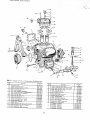
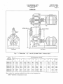
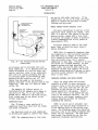
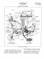
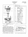
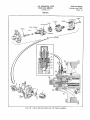
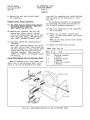
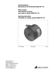
Typical3 3/4' x J compressor,Exploded View
-!
_1
1!
it
ca*a. conpfts$r tr"a-Efi-
Rcldvrtwrr
:E!g!:!r14-UIr
uskd, Hld Hok cover E;i;-
v3 Fn.
*Is'c.p'ftp|ied.L@
c*tr qa.
1..1 B:iB. oTtory.d RffiB%r*
=!qri4!4q
i,;::: .f"lT.Til "" "" "",
a$!!_qErlbr crer
u${,
=G,:r,.t.
udroi lbof . {, 6, 3 cvi.
$.d"" st e v.r,., b6.
Gr4, pisharF
hNe
^srtuiy,
vdve nde (r pcr olrnder)
edM ;dD!:6ii-
Head'comere$or'ReLdvatgeiyeg
diE3d6t3
-i
!t
Lj(kva3hd'spnq'4,nb*lb|t
45
YORK DIVISION AOFG WARNER
3%" 8ORE, V/W OPEN SINGLE STAG€
-22, 502, -717 UNTTS FORTU 180.20.Rp
Y 53 SERIES,
R -12,
4
3d
16
3 Required
- r/2" x
t)
, shot (1, 6, 3,
cllinde.. r/2 x 3 3/4")
csker, Discts4r edlotd
to varve
c6ket'Dischargekdbtdrovdve
G*d'
s.riB,
Pisr.n
Lockine Prsto!
Ri4,
o Nng' sighrcJs,
)
orsg!4
I I,r
s.-". c,p. b,r srr cr*J '"
cas5,
Prn (2 RcquiredJ
r
cdmpressidn (2 Re
Heaier,
cranlcas, 300wat,
r20 vorr (Ncn
D
vort (Nema
2a0
c.skct'ofung'capacitycont.olv've
4 and3
R€siEd r/r'x
TABLE
TABLE
2_
s r/2"
1-
B^RE COMPRESrcRS
TABIE
CONIPRES.SOR HOUSINC, AARE
3_
CRANKC}SE COVER PLATES
ccvernaieconpbrevjthcatsc'tycoi.
odd'l@vqrplr4udsjghtglJ$
TABLE
4- i^r A( | . 1 , u^ | 3uL
sr^clrnlrE
varve, capacty controL (sucdon
\rrThou-
,6r
aL FEaluRe)
P
vdve, capacity codror (Tehperrurc aciuated)
Riry, Redd4 (capscny cdnrdt vlic ro cove+hte )
rr*
ior
Irei
6
(2
Requred)
sd". P;;-T
Gp3ctycodtoLcompte@wthcover
TABLE
I
r".p.*
^cruared
4 A _CTPACITYCONT
Gniror (r.skp - r & rcyrrder compressors)
3, 12 & 16 cyrnder conpre6$r3)
v,be, Gtsciiy Grird (6-srp
!3 (Povef
^seDhry,
RlDore, $ctioi Ple$ure
Actuared)
12,
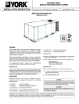
YORK DIVISION BORG,WAFNER
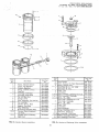
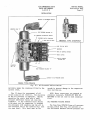
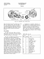
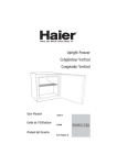
OETAIL_OIL PRESSURE
REGUT.ATING VALVE
Y-53IYPE OIL
PUMP
Bearing, Maitr, Pump End
2
3
Pin, Roll, Main Beaiing
5
Screw, Cap, Bearing Head (8 Required)
Clenk
064-00331
029 -03989
364-00325
364-05892
&d Pitr, OiI Fimp
o2t-02751
Gasket, BearinA Head
Valve, Oir Regulariqg (Complete)
8
9
m
ll
Gasket, Vrlve Cap
Ja-AiDs,
vatffi-
drs-ol06o
l5
Check, Ball
casket, Valve Body (Fibre)
Casket, Valve Sody (Coppe!)
Screw, Cap, Pump Cover
Gasket, Pump Cover
l6
&itrg,
I2
t3
028-00824
364-00329
029-00239
028-01256
029-0t8s3
028-00852
070-02537
02t-01425
064-20t09
O
t7
I8
l9
Oil ?ump Assembly (Roro! and Shafr, tdter Carier and pin, tdie! and
Bushing, Cove!, spiilg and insert Arso included ale "O, Ring (16),
Gasket (r5) aqd Cap Screws and Lockwashers (r9) ard (20)
screw, cap, Socker
20
2L
028-05163
064-03900
364-05893
Head
0rseit)
o2t-09272
021-0s265
023-0r304
comector, Straighr, r/4 SAn X 1/8 MpT
Y-49 TYPE OIL PUMP
No.
I
LF\.
No.
Craok and Pin, Oil Pump 364-00325
2
J
3
4
5
\j
4,5
Bearing pin, Oil Pump
2-
oir Pump, Bearing
Head and Oil Pressure RegulatinA Valve
4
029-0399r
Oil Rmp
026-03509
Oii Pump, Kit
364-05056
3alebGd,4*!le
FlG.
064-00322
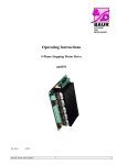
YORKDIVISION BOBG_WAFNER
3%" BORE, V/W OPEN SINGLE STAGE
22, 502. -717 UNTTS FORM 180.20Rp
Y 53 SERIES,
R
-r2,
F-'
\flE
e-3
fiV
--€
ro---€---€D
;i^\=-"
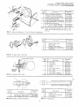
liston, Udoade!
Device
Screw, Cap tush Rod
Valve, Suction, Pin Type (
Spring, Suction Valve
valve Plare (R-12, -
064-00357
021-10650
064-003s6
Lft
Pitr
Ring, Reralning, Fo! Lift Pin
o29-t0757
-l
Vaive Plate (R-7I7)
Cam Ri4g, Lefr Hand
Spring
064-02673
valve AsseEibly, Discbarge (R-717)
(R 12, -22, -502)
o29-04021
varve Cage, Discharge (R
Valve Cage, Discharge
lR 12, -22, -5
029-090r6
-0399r
Cylinder Sleeve, Plain
-0037i
o2\- t2428
02r
05268
064 72\64
Sprjng, DLschalge Valve
Bolr Assenuy, Valve S€at
029-0401
064-00374
364-02674
Nut, Dischalge Vatve Bolt
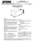
FlG.
3-
cyrinde! Sleeve Assembties
FlG.
4- 5sti6.6.4
pi.chaige vaive Assemblies
YOBKOIVISION BORG_WARNEB
Scieen, Suction stlaitre!
Lockwasher, Spring
029-03447
Nut, Sfainer Cover
021-00466
Q2t-Q5269
064-00377
Gasket, Straine! Cove!
070
021-0r483
064-00379
EXTERNAL OIL FEEO LINE
2
3
4
5
064-0.r739
064-24443
o28-07424
028-07898
RinA, Shaft SeaI
RinE. "O'
Rias, Quad-Bak
Krt, Shait Sear Repalr
Splils, Helical, Shalt S€al (r2 Req'd)
Pin, Roll, Coverplate
029-04290
029-092r4
7
8
BaU, Couar
9
i0
Bearing, Main, Thnst
Screw, Cap, Bearing
!2
Head, Bearing, SeaI
064-00292
l3
Screw, Cap Hex Socket Hd.
ozL-02590
l5
Cove! Seal End
Gaskets, Beadng Head and Coverplate
L6
Screw, Cap Coverdate
t7
PIug, Diaic
Ell, r/4 sAE
464-04722
028-00824
021-09204
064-24444
tl
029-01845
064-00324
02r-01483
027-Q5247
na&,
t8
I5
364 06577
029-040i0
l9
x r/4
Tee, r/4 SAE X l/4
Nut, 1/4 SAE
M?T
SAE
X r/4 MPT
Tubina, r/4 Sreel (Order bv
Ft.)
023 04729
ofi -04r00
02r-0s675
003 00235
SHAFT SEAL ?ARTS Y 49 AND Y.sI MODELS
Kit, Shai! Sear Conversion (Cortaios
364-05434
Mate al to Convert Y 49 or Y 5I
Type Sear Assembly ro Y-53 TWe)
Nut, Seal CoUar Locking (2 Requiled)
064-003r3
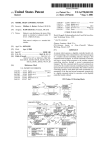
FlG.6-
Shafi S.al ano Bealing Head
-Y
53 Tyoe
6
locK DtvtstoN aoRc
waqNER
BORI. V w OoEN S|NGLE SIAGE
q .12 -22.3,"
q02
_7tr IJN|TS FORM l8o.zo.Rp
w
53 IER|LS
I
Bolt, Bearing (4 Required)
064-0032i
2
Bushing, Taper (2 Requiled)
Screw, Ca!, Bearins Lockrne
Wa6her (10 Reqd.ed)
N'tt, Self Locktns (s Reauired)
Bearing Assembly, Main Cenre!
(r2 and l6 Cytinders)
Pin, Dowei, Cenrer Beariog
Union, l/4 s,{E x l/8 MpT
064-00320
021-01598
3
4
5
l-5
1
021-05r55
02\ \3257
364-00317
464 -00322
023-0r304
Norer Torque rorbearingbolrs (rrem 1) 60 Fr. Lbs.
Tolque ior bearing locking screw (Ireh 3) - 20
F-7
Bealjng
-
l2 and
16 Cylinder Compressois
Casket, Sighr CLass
028-00778
026-43992
Packing, Sigh! Class
028
-
01519
064 -40302
Q2\-0i471
FlG.
8-
Orl S,Ahr class
'
Bulb Type
I
022-00530
2
068-0454i
3
4
068_045,12
5
HOLE IN
-8
FIG.
9-
7
t'8
Crantcase Floar valve
Plpe Nipple, Special
Float Valve Assenblv
068-04545
021-09610
068 -01s49
068-04544
068-04s46
029-05340
021-0136r
02r-05289
FlG.
l0-
Packinc - lntelnal Oit Header
FlG.
1l-
oi1 srraine!
MISCELLANEOUS
COMPRESSOR CASKETS, COMPLETE SET
364-0636r
364-06362
364-06363
364-06364
364-06365
8 Cylinder
3-Way, fo! Unloade! Cover
Conplessor OiI Piessule
422-0t218
Solenold, Unloade!
025-09704
02s-0970s
solenoid,
sPECtAr. TOOI
- Il5V
Unloade! - 208/230V
02(-r2f67
S
Spanner Wrench
- Sbat
Seal Nur
- y-49
and 53
TW€ Shaft Seals
Socket wrench, Relief Valve
- foa Comlression of ?isior Rings
Insulhns Prsron
Funnel Ring
When
G
04r-04136
068-029r3
064-00240
UIDE
Retarning Chp, Sucuon valve | 064-03447
FlG.
12-
Sucrion valve Retaining crip
subied to ch.ng. wirh.ut Nori.a
PPC
l
17l .20
Fo.m 130.20-RP
Coder S(EFG)
Fom r30.20-RP coded
460
^
f,fi
CENTRAL ICE MACHTNE COMPANY
Refrigeration Supplies
TOLL
-
FREE
SOO_228-7213
.-464
v/l|l c0
PREssoR
Folm lao. 20- N I
(3w-r)
uNrls
FNEON AND A}IIIONIA
3-3/4 x
Page
3
I
DESCRIPTION
GENEIIAL
PUr'rP.0uT aN0 sY.PASS
C01r
I ECII0r{S
'the 3-3/4 X 3 V/W conpressor unils are
available for use with renote condensing
equipment (either water cooled condensers
or economizers) in capacilies ranging from
5 through 195 tons of refrigeration for
both single stage and booster applications.
These units conbine vibration freer
quie! and efficient operation with reduced
floor area and head room. Static and
dynanic balance pernils upper floor mounting wilhou! special foundalions.
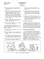
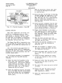
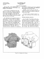
Fig. 2 - Six Cylinder Alulonia
Figs.
I
appearance
throuqh
of the
Conpressor
4 show the general
compressors used on lhese
units, while Fiqs. 5 throuqh l0 show lhe
overall dinensions and connections.
Fig. I -
Four Cylinder Freon Conpressor
Each standard cornpressor unit is
furnished with a single compressor nounied
on a base with belt drive and guard (or
flexible coupling) r oil separator (for
anr0onia), crankcase heater (for Freon) i oi1
failure swilch, stop valvesr high pressure
cuiout,
gauges and gauge board.
'lhe 3-3/4 x 3 conpressor units are flade
the V-Belt
Crive and 4, 6, 8, 12 or 16 cJlinder sjzes
ir 4, 6 and I cylinder sizes for
for direct drive.
Fig. 3 - Six Cylinder I'reon Compressor
@**::',:;:J1*#*
v/l{ co
SERVICE IIANUAL
Instruction 3W-F
PREsoR
uMTs
FREON AND AMIIONIA
3-3/4 x
Page 2
3
DESCRIPIION
NOIIEI{Ct"ATURE
Arfinonia
or
Freon
No. of Cylinders
Styie
RPI{
t-
Desighation
Direct. Drive
Econornizer (or Renote
Condenser)Applica!ioh
I
I
E
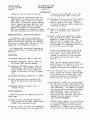
Fig. 4
-
Sixteen Cylinder trreon Cornpressor
SPECI['ICATIO}IS
STANDABD COUPNESSOB UNIT
Crankshaf! - Cast ironr counter-eeiqhted
and balanced to nininize vibration.
Eousiira - Close grained iron castirg.
Contains cyl inders, crankcaser suctioh
strainers. and relief valves; equipped with
hand hole plates abd oil sighr 91;ss. Bemovable cast alloy iron sleeves are fitted
into the cylihders. Integrally cast water
passeges in aMtonia housing to keep working
parts of ooitpressor coolt
Bearinqs
bearings
Pistons - Cas! iron plug type pistons wilh
chroEe plated compression rinqs and vent,i_
lated oil rinqs.
Lubricatio, - Atl bearing surfaces and the
shaft seal are pressure lubricaled bv a
geared pump equipped with an externai disc
Fuctior! and.Discharoe Va1ves - Rinq plete
rype ol stainless steel with cast iron re_
taining plate.
qonneqtinq Rods - AluninuE aIIoy wrLh rein_
torcecl crank pin end. produced by full
permanent mold process. Drilled for oil
distribution to the piston pins.
Shaft Seal - Single, spring loaded, balanced
sealr simple in design end usinq no
diaphragns, Cast iron seal coliar with
carboh seal ring.
-
Sleeve type load and thiusr
aluEinum alloy.
of
type oil fllter in puDp discharge, a pressure gauge and a regulating valve,
Suction Strainers - Strainers, Lhe bodies
of which are recessed in the compressor
housing, are equipped with two tilicknesses
of
35 mesh wire screen, Each slrainer is
lined at the factory with a cloih bag. This
cloth bag is used to prolecl the conpressor
v/fl
cotPRBssoR uNrTs
SERVICE IIANUAL
Instruciion
FREON AND AIdMONIA
3-3/4 X
3W-F
page 3
3
SPECIFICATIOM
on iniiial sta{t up. It is then renoved
and ret.ained for future use after piping
changes or addilions.
soleplate with bolts and dowel pins
ntounting on concrete foundation.
Crankcase oil Heater (Freon ohlv) - An
insert-t.ype 300 $att crankcase oil heater
complete with junction box and cover rs
furnished inslal]ed on each conpressor.
The connection is 3/4" pipe thread and the
sieel sheath is approximately 12" 1orq.
Available for either 110 or 220 volts,
oll
for
0i1 Failure Switch - Pressure differential
nanual reset type which responds to pressure difference between oil pressure and
suction pressure. Stops motor on xeduced
pressure.
ACCESSOBIES
Pressure Relief Valve - Standard, spring
loaded, ball check type which allows discharge gas to escape into suclion gas passages, These valves are set to open at
250 psi differential.
Qischarqe Line 0il Separator (Freon Onlv)
tepara!6rs are furnished complele with
float. Furnished as standard for amnonia.
0i1 Leve1 Indicator - 0i1 sight glasses are
installed so that the oil level may be
readily observed.
usecl
A1l conpressors have hand hole covers
adapted
0il
- Capacity reducers, including sleel tubing, orifices and hand
operaled sl,op valves are incorporated as
standard. l{hen so specifiedr the conpressor
is fitted with solenoid valves to allow for
autonatic capacit,y reduction.
oil Level Float - Floats to be
with parallel operation of conpressors,
Crankcase
Receiver
Capacity Reducers
Thexmonet.ers (Annnonia 0n1v)
- A t.hernometer
is fulnished for insertion into the discharge nanifold. A thermoneter Lvell is
provided at the suction cohnection on 4, 6
and I cylinder sizes.
Controls and eauqe Boaxd - A high pressure
cutout is furnished with each cornpressor
fo! renote nountinq. Also a gauge board
wjrh high and lod, pressure gauges is
f rnished $Jith each conpressor.
Compressor Connections - Hand whee.l type
suction and discharge stop valves and welding flanges for connecting into system are
nounted on the anrronia compressors. Freon
cornpressors have seal cap valves.
hive - Either V-belt drive or flexible
coupling for direct drive.
Steel Base or Soleplate
base
- Structural steel
wilh trrotor rails and belt guard or
for
use
of
these floals,
- Available
when required.
Auto,natic Capacitv Reductron
va-tves. necessary tubinq and
- Solenoid
fittings are
available to give autonatic control of
capacity reduction. The solenoid valves
may be operated by eit.her a thernosrar or
a suction pressure conirol.
Oil Equalizils Connections - All
cojrpressors.have cover plates tapped for
use or equalrztng connections.
Gas and
Vibratiol IEqlators - Vibration isolator
springs are available for upper floor
mounting or any other mounting where
ration must be kept to a nininum.
vib-
Punpout qr,rd qvpass connections - Necessary
valvesr fittings and pipe for cross connect_
ions are available when ordered.
c_ggg9-.Board.}.iirh
Cutout - Iuade for
c-Vz suctton and!.p!
Orscharge pressure gauges
anq nrgn and t0w pressure cutouts. Gauqes
and low pressure cutout included with b;ard.
Motors and Staiters - tlotors and siarrers
are available when ordeted.
v/ti
SERV]CE MANUAL
Instruction
3l{-F
co[P8EssoR uN]Ts
FNEON AND AIIII{ONIA
3-3/4 x
Page 4
3
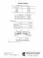
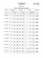
PT]YSICAL DATA
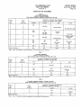
ta8tE r
COMPN.ESSOR DATA-DIRECT OR BELT DTIYEN
COMPRESSOR
Cylind€rB
4 Cyl.
6 Cyl.
Bore
StIoke
3%',
No. Compression RiDgs
2
8 CVr.
16
s3l,
s%"
3',
2
I
2
1
231'
2%"
2%',
2
I
No. "Vent. Oil" Ring6
Pin Diamet€r
Pin Lengih
23/4"
Suction
L
I
I'
Discharge
I
I
I
I
I
1
Cylinder
CoIIecting
Ito l
10'
10'
10"
10"
2
2
3
3%"x3"
3%'xs".
Rodg
ClanlsbaJi
Size of
Mair
Bearings
Cyl.
Cm,nk and
t
Wrbt Pin
Number of Beariqs
Ss,l End
Center Bearing
Pump End
2
3%',*'
z%'vs'
;r,.ar. ;r];zr, ,r",n
2W
Crank
Pin
Dia.meter
Lengih
I%',
Shajt KeJ'way
width
Depth
%'
%'
Oil Charse
Gallons
4
, 3X'xaW
2%'xB%"
23/{
2r<'
2x/4'
22's'
3%',
2%"
vl
,6
%'
%
%
5
TABLE 2
UNIT DATA_DIRECT OR BELT DRIVEI{
PIPING
CONNECTIONS
UNIT
MODEL
NUMBER
Freon
L€ngth
With Motor
widrh
2lz"
2lz"
69'
69'
69'
69'
39%',
39%',
2Y2"
Heisht
46',
(No Motor) Poudg
3049-58E
3049-5DE*
3"
3"
2Y2"
75%',
301/2"
4arN6'
1600
1600
1600
1600
1500
3069€8E
306948E
3"
3"
4"
4"
21h"
7e
43s/ o'
49r,4'
1750
4s%'
76',
43s4a'
49t/2"
1750
1750
2Y2"
a294a'
34%',
52%'
1640
3"
76',
48%',
1850
1850
3049-28E
3049-38E
3049-4BE
3069-5BE
3069-5DE*
308948E
21/2"
21/2"
21/2"
I NHs
Dischargc
MAX. OPERATING
WEIGHT
OVERAIL
DIMENSIONS
2lz"
2y;'
3089.5BE
3'
3089-5DE*
3"
16',
76',
87Xa'
Two 2Yz"
Two
1O4%"
3129-5DE*
3169.5DE*
Two 3"
r05i%a'
3r29-3DE*
n5%'
3s%"
40y{
8%;'
45"
46%',
46%',
46%',
48%',
z4%"
5r%'
1740
38"
58y{
38',
58%',
3280
3280
s8r4'
57%',
3480
V/T
COIfBESSoR UNITS
SENVICE M/INUAL
Instruction
FREON AND Ai,II'IONIA
3-3,/4 X 3
PH}SICAL
C()MPRESSOR
MOTOR
Flywheel
R.P.N.l
F-3049"28E
720
F-3049-3BE
F-3049-78E
I',-3049,98E
F-3069-5BE
1190
1400
rl70
I',-3069-6BE
I-3069-88E
F-3069-9BE
F-3089-5BE
I-3089-7BE
F-3089-9BE
16"
7750
1170
1440
1750
6/c"
63/e"
t6
63/e"
12"
67s"
t2"
1750
5y2"
634"
16"
F-3049-58E
*. l racc
I uru l widih
R.P.M.l
| \6"
15Y2"
16"
s50
|
#/s' I
1450
1750
8%
51/2"
6%"
51/2"
1450
7750
t034"
gYs"
r0%"
t2"
6%"
I
r45o
1oVs"
1800
s%"
I
I
12"
12"
6Ys"
63ls"
|
16"
67s"
67s"
62.4
57.0
64-20235
63/e"
63/s"
13,,
67s"
96"',
90"
1800
6a/s,,
64-44965
64-20225
6%"
r45o
12"
39.0
tF/s"
I
72'
50.4
96"',
93/+"
67s"
I
96"
63/s"
1lys"
16"
16"
6ys"
63/{'
t750
143/a"
72"
64-4434S
64-2021S
1450
12',
|
25.1
22.2
96"
1750
r45O
l8o0
63/s"
63/e"
13"
r0.h"
143/e"
1800
12"
i
I
1450
1800
l3'
(f/a"
10.'/s"
eF/x"
I
67s"
r4so
67s"
6%"
675"
|
i
l1Ts"
64-4435S
45.0
64-20245
90"
90"
62.4
61.2
64-4436S
64-4450S
s6",
9t'
62.4
56.6
64-44445
64-6125
90"
90"
50.4
40.0
64-4437S
9!',
62.4
64-4438S
64-2026S
9Cr
62.4
61.2
64-443frS
9V'
96"
6b.4
56.6
80.6
1800
t0"
6%"
C
C
cog.
cog.
90"
9U'
1450
1800
t43/s"
(f/a"
C
cog.
90"
87.4
cog.
90,,
85.6
l2'
83/2"
()
64-4444S
9A'
9t'
63/e"
1450
|
Part
9?"
97"
63/e"
1450
12"
Number
13'
6%"
t2"
No. lsection I Insid€ | Ddve
Iry{'
6z/s"
12"
12"
DRIVEPKG
r450
r750
12"
12"
6%"
V-BELT
Pulley
_.
Dh Il riFace
iiu,
|
DATA
3_Y.BEIT DRIYE DATA_FREON
TABLE
trIodel
Number
3W-F
Page 5
66.2
64-2025S
64-4450S
64-4444S
64-61?S
64-4439S
64-2027S
64-4440S
64-4451S
v/i{ corPnBssot
SMVICE MNUAL
Instruction 3l{-F
Page 6
uNrTs
FBEON AND AUTONIA
3-314
x
3
PHYSICAL DATA
TABLE
I'NIT
|{-Y.BEIT
DRIYE DATA-AMMONIA
MOTOR
COMPRESSOR
Pulley
Fly'vheel
Model
Number
AJO49.2BE
R.P.M.
Dia.
750
A-3049-5BE
A-3069-3BE
A€O694BE
A3069-5BE
1170
a_3o8r4B1l {or5
a-3089-5BE
1170
Dja,
I Width
No.
Sec-
tion
Non. Max.
Imide Drive
I€nsth bhp
Palt
Numb€r
1Yz'
8%"
E%',
7
97',
|Yz"
7)/z!
6%',
7
97'
6%'
6
96'
4,3.2
64444
10"
64-4441S
,o.
64-609S
5%',
1750
8%"
5%"
7
97'
27.2
64610S
6%'
1450
t\t6'
(9/2"
6
96',
53.3
64-4443S
6W
1750
sr{
6%',
6
96',
42.8
646rrS
6W
1450
$"
6%',
6
96',
62.4
6+44455
6%',
1750
10y{
6%',
6
96"
6+61?.S
16,
6t1',
1170
tzlti
6%"
6
C
105',
64-614S
16.
6%'
1450
10,
63/2"
6
c
96',
43.2
64-4442S
16',
6%'
1750
6W
6
C cog.
96'
58.8
64-44475
6%'
1170
6y{
6
c
105'
60.0
64615S
63/{
1450
rrw
6al,
6
c
96',
6W
1750
syl
6%"
6
C cog.
96',
62.5
64-4449S
6e4',
1450
l3'
E%'
6
C cog.
96'
a7-4
w4455
6%'
17fi
10z|'
8y{
6
C cog.
s6'
75.2
644448S
6%'
1170
6%'
6
c
105'
6%'
1450
rr%'
634"
6
C cog.
96'
76.0
644446S
634'
1750
s%'
6%'
6
C cog.
96'
62.5
64-4449S
lCcos.
96'
a7
-4
M46S
lCcog,
s6'
75,2
64.4448S
1170
10r5
lYidth
Face
1450
1015
475
R.P.M.
6%"
A-3049-3BE
A.304948E
Face
V.BELT
8%"
63'
TY
6%',
6W
roy{
6t1'
6
6
64-4443S
64614S
VA{
SMVICE IANUAL
COTIPBESSOR UNITS
Instruciion
FNEON AND AI{MONIA
3_3/4 X
3W-F
Page ?
3
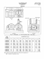
DII,{ENSIONS
Fig. 5 -
Dimensions
-
41 6 and
UNlT
F-3049-2BE
F-3049-3BE
I
A
B
69
385/e
38%
F-3049-58E
69
69
F-3049-7BE
F-3049-9BE
F-3069-5BE
69
69
69
393/ta
399,re
F-3069-6BE
F-3069-8BE
F-3069-98E
69
69
69
F-3089-5BE
F-3089-7BE
F-3089-9BE
69
69
69
C
4+
D
E
46lz
- BeIt Drive
F
G
E
J
2lz
14
1o1s/ra
46Yz
t4
70r5/16
133/a
45Y4
46Yz
14y1
10154s
15:%
2Yz
2Yz
3
45Y1
46Yz
141/e
1016/16
753/+
461/z
14Y4
1017ro
75Y1
4orl:'t.
45y+
44Vs
rorV:'t.
40r1i6
47ya
393/ra
48la
2Y2
2oYz
2oYz
2oYz
3
21k
2oYz
2Y2
2o!z
153/+
3
3
2Yz
2oYz
10r%6
753/+
4
lors/\6
ror%6
153/a
2lz
2lz
Yz
2oY2
15V+
2Yz
2oYz
3
3
3
2oYz
48ls
14%
r4Ts
47t/a.
48!e
l4Ts
41
47Y2
46%
l6e/+
471/2
463/s
747/s
147/s
rorYrl
41
r01%6
l|V+
47Y2
463/e
14Vs
101%o
15Vt
401.1/16
4orls
48r/s
for rcmoving cmnlshaft, {rcm eiiher
33%"--centerline of compressor to wall.
Space needed
Cylinder Freon
DIMENSIONS-Inches
MODEL
NUMBER
I
eDd of coEpressor
is-
4
4
4
2Yz
lz
201/z
V/W
SMVICE IIANUAL
Instruction
Page
I
COIIPRESSOR
UNIIS
FBEON AND AMMONIA
3W-F
3-3/4 X
3
DIIIEiIS IONS
%"
WATER OUTI.EI
]/." WATER OUTLFT 6
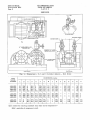
Fiq. 6 -
4
CYL.
CYL.
Oimensions
- 4, 6 and I
DIMENSIONS
UNIT
MODEL
A3049-3BE
ASO4MBE
A3O4F5BE
A306988E
43069-48E
A3069-5BE
A30894BE
a3089-5BE
l&he
J
rb%
r5%
2tl
2h
2r4
20%
2tll
20%
t4%
14%
14%
L
M
N
5%
r4%
l4
ro14
t4
r04l
14
14
t5%
2%
2tA
w14
ro54
r5%
211
2tk
2.014
43% 46%
43% 46%
43% 48X
49%
14)4
\2%
tz
12N
2%
2%
20N
141/4
2X
2014
t2
5
5
49N
L4%
12r4
16%
16%
16%
2N
49
2th
2%
20%
12
5
48%
47%
47%
147/4
ror4
16%
16%
3
3
3
20%
zs%
76
76
76
76
45
45
39%
44
3S%
44
40%
45%
48X
L4%
roll
rox
for rcmoving crankshafi frcm either
33tl8"-centerlitre of compressor ro w4...
Space needed
Drive
46%
46%
46%
46%
69
69
69
69
76
- Belt
II
NUMBER
4304$2BE
Cylinder Anrcnia
3
eDd of compressor
wx
i3-
3%
3%
\434
r4'/a
-
8%
8%
a%
a%
V/I{
SERVICE ITANUAL
COIIPXTSSOB UNITS
FREON AM Aid,IONIA
3-3/4 X
Instruction
3lil-F
Page 9
3
DII,iENSIol'ls
sucfloN <oNN.
Fig. 7 UNIT
f,IODEL
NU]IBDR
D.imensions
H
- 4,
6 and B Cylinder Freon
B
c
D
E
F
G
E
J
K
RPM
lo17:t'
17%
3
3
2Y2
2r/2
117s
117s
1170
3
4
21/z
173/s
1170
2Yz
lIs/s
1750
4
3
3
117s
1170
ll3/s
1750
r'3049-5DE
25
751.a
3oY2
a8'lie
40
755/u;
30y2
481Y1e
14Y!
l0r5/16
F3069-5DE
F3069-9DE
40
14Y2
72r/,s
193/a
12r/re
193/s
76r%6
341/z
48%
521a
761346
34lz
5IY!
52'L
82%u
341/z
sr/t
87/ra
34Y2
5r1/l
50ys
50ys
r4%
rors/r6
14%
ro'346
for rcmovirg crankshaft ftom either etrd of compressor
33ys"-centerline ol compressor to wall
Space need€d
Drive
DINENSIONS-Inches
}tax.
HP
F3049-9DE
I',3089-5DE
F3089-9DE
- Direct
193/s
is-
1750
VA{ CO
smvrcE tfAtitiAl-
Instruction 3l{-F
PRESSOB UNITS
AM) AT'K)NIA
3-3/4 X 3
FNEON
Page 10
DII|ENSIOI{S
Fig. 8 UNIT
MODEL
NUMBER
Dimensions
- 4, 6 and B Cylinder AnLnonia DIMENSIONS-IEohe
Md.
E.?.
A304F5DE
A306$5DE
A3O8F5DE
48
52t4
\ox
I r4y1l \o% | r11b
| r41'e | 12N I rs9e
I r4rs I to% | re%
for removing craDkshaft lrom either
33 7s '-centcrlin e of compr$sor Lo w4...
Space needed
| 2r'12t6
| 2r,l2L6
|
3
3
eDd of compressor
is-
Direct Drive
V,/II CO
SERVICE MNLI/TL
PRE.SSOR UNITS
Instruction 3lt-F
FBEON AND AIIIIONIA
3-3/4 X
Page I1
3
DIIiIENSIOI'{s
Fig. 9 - Dinensions -
12 and 16 Cylinder Anmonia
NUMBER
4312S-3DE
A312g.5DE
A3r6$5DE
Dlrect Drive
DIMENSIONS-IDCb€S
UN]T
MODEL
-
E.P.
KILIM
56% | 5876
I -
56761581s1|
| 23%
L2
lrts%
\2
Spacc necded for removing cfankshaft from citirer cnd oI compressor
66%"-ceDtcrliDe ol coDrpressor to wall,
is-
SERVICE
V/I'
I,IIANUAL
Instruction
COMPRESSOR UNITS
FREON AND AI'IIONIA
3W-F
3-3/4 X
Paqe 12
3
DIldEIISIOI.|S
Fig. l0 -
Dimensions
-
12 and 16 Cylinder Freon
I:tt2SJDX
13129-9DE
13169-5DE
F3169-9DE
Drive
DIME\SIO\S Inch.s
UNIT
MODEL
NUMBER
- Direct
EP
-_:-
r0r'l
100
101]Z
100
150
104
1051i4
56%
56%
D
H
Sara
;
581,4
5?h
t6%
lor removing crankshalt Irom either end of
66y2"-centerline of compressor to wall.
space needed
%%
5
B%
6
23%
23ra
6
compressor
11?0
t?50
11?0
1?50
is-
IlsTALI,ATION
GENMAL
installing one of these compressor
must be realized that these are
precision builti high speed machines, The
Before
units. it
iaportance of cleanliness during installation cannoi be over-emphasized. Dirt,
scale. rust and any other foreign matter
nusl be xemoved fron the enlire system
before the compressor is operated. The
snallest palticles of foreign natter can
score pistons, cylinder liners, bearings
and seal surfaces! and mus! be prevented
fron reaching these parts,
A closely woven cloth bag is inslalled
in each suction strainer of every new
conpressor as an added precaution to prevent
diri fron reaching lhe rnoving part.s, NoTE:
These bags, are not designed for pernanent
system cleaning and must be renoved afte!
the jnitial operating period. Therefore.
do not depend on the cloth bags to do a
permanent cleaning job. The system ltust be
cleaned betore operation.
The system! into which one of these
conpressor units is to be insialled, nust
be designed to pievent heavy or prolonged
liquid slop-over back !o Lhe cornPressor.
othe! precautions $hich nust be observed
jn inslalling these cornpressor unitsr nay
be found in Instruction 2D. GENERAL II\STRUCTIoNS,
FREoN SYSTEIE
or
2A AUfioNIA SETE S .
INSPECTION
As soon as it is received. t.he uni!
should be inspected for any danage done in
lransii. If danage is evident' lt should
be noted on the carrier'6 freight bill,
A separate request for inspection by lhe
carrier's aqent sho ld be made in wriling
V/W
COMPRESSOB UNITS
FBEoN AND AllliIoNIA
3-3/4 X
3
SERVICE IIIINUAL
Inslruction
3l{-F
page
13
ITISTALI"ATION
at
once (See Instxuction 2F).
IIIIMLING
All of the units are shipped on skids
which should not be reBroved until the
apparal-us has been placed in ils approxinate location. Care nust be taken noL Lo
damage the external oil piping on the
conpressor when noving the unii. Shipped
in a carton allached !o the skid are a
shaft seal collar nut spanner wrenchr a
high pressure cutout, oil failure switchr
discharge gas thernometer (amnonia), funnel
ring and 3 Allen set screw wrenches. The
gauge board is shipped in a separate box.
For renoving the crankshaf! fron eit.her
of the conpressor the space needed from
the centet ]ine of the conpxessor to rne
end
wall is:
Cylinder
E I Cylinder
12 616 Cylinder
6
32-3/8"
33-1,/8"
66-1/2.
LOCATION
The unir. should be located in a dry and
sJell lighted roont with sufficient space
around ii to allow roorn for inspection or
Basenent - nenove a portion of t.he basefient
floor so that a concrete base car De poureo
resting on the ground, extending 6', t; B"
above the basement floor and having suffi_
cient space on all sides to install corkboard. (See Fig. ll) If rhis nerhod of
isolating the compressor unit cannot be
used, place the uni! on a level concrere
slab 6" to B" thick and the use of sprjng
type isolators are reconunended, (See Fig.
rr)
Floor - For upper floor nounting,
sprinq type isolatots are available when
ordered. Fiq. 12 shows the three sprrng
assembly used for the 12 and 16 cylinder
units and the single spring assernbly used
for 41 6 and B cylinder unirs. Do not use
corkboard under these unit. s.
The standard locaiion for the isotat.or
assemblies is shown by Fig. 14. These
locatlons are satisfactory for nost installalions but on occasion it nay be necessary
io move the assemblies to compensale for
heavier or lighter loads at the motor end.
Upper
Al1 compressor unit bases have additional
holes drilled at the factory to allow relocating the isolator a ssenbl ie s.
service. See fable 2 for the o,rerall dinof these unils.
ensions
The uni! should be located in a space
having naiural ventilation to dissipale the
heat given off by the conpressor and motor.
If sufficient ventilation is noi availit nay be necessary !o add lorcecl
vent,ilation io prevent excessive bearing
temperatures and over-heating of the nrot,or.
l{hen the conpressor unit is t.o be installed in a location where noise is an
important factor, all prinary sources of
ab1e,
noise should be elininated upon installation.
FOUMATION
AND
OUNIING
- If the unit is to be locareo on
an earth floor i! should be placed on a
Ievel concrete slab 6,' to B', rhick. (see
Ground
Fig, ll)
.
Fig. ll -
Suggested Compressor UniL
Fourdat.ion
VA{
STRVICE MANUAL
Instruction S!{-F
Page
COMPRESSOR UNITS
FREON AND AMIIONIA
3-3/4 X
14
3
I16TALTATION
(a) Deternine the number of springs required so that each spring t{i1I support
its approxinate design loadr keeping
in rnind that an even nunber of springs
nust be used !o support the base evenly
on opposite sides.
(b) Raise the conpressor unit 6" off the
floor,
(c)
the mounling washeri mounting
cap screw and shipping stud nut fron
Remove
the isolator
unit.
(See
Fiq.
13)
(d) Insert the shipping slud lhrough the
hole in the conpressor unit base. See
Fiq. 14 for the suqgested location of
the i solator assemblies.
.!e_.1!_]6_s!.,
(e) Flace the nounting $ashe! on the shipping stud and fasten the isolator unit
!o lhe base with the shipping stud rut.
Gee Fig. 13) Be sure the springs are
properly sea!ed.
(f)
Lo$er the unit so that the isolator
assemblies Lake the full wejghl.
.-.[.|.s***
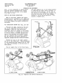
Fig.
12
- Vibralion Isolator Assemblies
Holes are provided
in lhe
bottom plate
of the isolator assenblies to bolt
the floor if desired.
them to
W
Each isolator spring is designed to
carry 330 lbs, when conpressed to a working
length of 2-13116".
Since it is not known what weiqht notor
be used, the maxinum number of splings
that should be required are furnished tlhen
ordered, On sone inslallations not a1l
springs lrill be required.
will
Fig. 13 shows lhe nethod of applying
these isolator spring assemblies to each
side of the base on the 12 and 16 cylinder
units. The procedure is as followsi
Fig, l3 - Applying the Vibration Isolator
v/l{
collPnrssoR uNrrs
SMVICE MNUAL
Inslruction
FNEON AND AIIMONIA
3-3/4
x
II\STALIATION
o
o
o
o
o
o
o
o
4
CYLINDER_SELT ONIVE
o
o
o
o
o
o
o
o
o
o
o
o
o
o
o
2""---13r"'l/'l
Fig.
14
-
Suggested Locat.ion
3w-F
Page 15
3
of Vibration Isolator Assenblies
VA'J COIFRESSOB UNITS
FREON AND AMMONIA
SMVICE MNUAL
Instruction
SW-F
3-3/4 X
Page 16
3
INSTALTATION
(g) Level ihe unit base by shiftinq the
spri g assenblies to axother hole if
bolted !o the unit base using the
mounting washer ard cap screw. (See
Fiq.
(h) Afler lhe uniL base has beer leveled,
neasure the distance fron the floor to
the boilon of the unii base. This
distance should be 3-5/8" for each
spring, If it is less add springs, if
nore remove springs. The unit should
now be level and the distance fron the
floor to the unit base should be 3-5/8"
at a]l springs.
(i)
Refiove
the shipping studs and nuts
install lhe
scre}r.
(j)
and
mounting washer and cap
(See Fig. 13)
13)
(e) Before ld'|lering the unit, place lhe
spring and base plate directly below
each top plate. Be sure the springs
are properly seated flhen lowering the
unti.
(f)
The distance fron the floor io the
botton of the unit base should be 3-5/8"
a1r each spring assembly to obtain the
approximate loadinq of 330 ]bs. on each
spring. (See Fig. 13)
REFR I
GERAI{I CO}INECTIONS
The application of isolators to the 4,
6 and B cyiinder conpressor units js
similar to that for the 12 and 16 cylinder
except as follows:
Before shipment from the facloryr these
conpressors are given a preliminary test
run, and charged wilh the proper anouni of
oi1, To insure absolute cleanliness, it is
importan! to keep the suction and discharge
service valves closed during installationr
until the final conneclions have been nade.
(a) 0n1y single spring assemblies are
Discharqe Line
The
isolaior
assemblies nay be lagged
to the floor if
(See
Fig.
desired.
used.
oi]
Separaior
12)
(b) Fiq. 14 should be used to deternine the
primary location of the spring assenF
bl ies.
(c) The shipping boli, mounting washer
and
cap screw mus! be rernoved before applying these isolators. Gee Fig. 12)
(d After the unit has been raised 6" frorn
the floorr the top plaae should be
6z"x5"
0n a modern conpacl conpressor such as
!his, the oil capacity of the crankcase is
linited and oil must be added frequently to
offset that which leaves the conpressor and
is not returned. For this reason, it is
recommended that a discharqe line oil
separatorr an oi1 receiver and a crankcase
float valve be inslalled. i,lljth this
arrangement oi1 may be added to the receiver
through its charging connection. This
receiver acts as a reservoir which auto-
coMPAEssoR
Fig,
15
-
0i1 Belurn Arrangenen!
VA,] COIPRESSOR UNITS
SERV]CE MNUAL
3w-F
Instruction
FNEON AND AI{MONIA
3-3/4 X
Page
3
l7
INSTALUITION
coflNEcT T0 c0MPRESSoR SUCTrol
LOW PFESSURE 8ELLOWS ''AN
PRESSIJRE DIFFERENTIAL SWIICH
P8ESSURE SWTCI]
TER/II
ALS
AMMONIA TYPE z7sAPIONA
WIRE TO CONTROL
HICH
OEVICES
PRESSURE BELIOWS
FREON TYPE 275APIO
Fig. 16 - 0i1 Pressure Failure Switch
rnatically keeps the craEkcase filled to the
enouqh to prevent
damage
to the
conpressor
correct Ievel.
lvhen start.ing up!
Fig. 15 shows the arrangeflent. of oil
return using an oil receiver. The elevatio
of ihe oil receiver is important. Durinq
operation the staiic head plus a srnll
pressure difference forces oil inlo lne
crankcase, If the crankcase float shoutd
stick openr and the compressor is stoppedi
the pressures u,ill equalize and the oil in
the crankcase and in lhe receiver will seek
the same leve]. This level nust be 1o"{
li0lE: l{here coropressors are mounted on
vibration isolatorst FLEXIBILITY MUST BE
PROVIDED
float.
OIL
in the oil line to
each crankcase
PNESSURE FAILUBE SWITCH
The Penn Type 275AP10 Freon oil pressure
Gee Fig. 16) operares on
the difference between suction pressure and
failure switch
v/l,[
SERVICE I,TIINUAL
Inslruciion 3ll-F
coMPREssoR uNrTs
FBEON AND AIIII1ONIA
3-3/4 x
Page 18
3
I IsTALIATION
are put in with r,rhite lead only. If ihe
lapped holes are not to be used, ihe plugs
should be removed and pu! back in usinq
litharge and glycerine.
WATEn JACIGT
PFING Gnunonia only)
AII water connections in and out of the
conpressor waler jackels are tagqed. (see
Figs. 6, I and 10) The piping to the compressor jackels should have a stop valve
to control the supply in order to maiBiain
a water temperature out of tire jacket at
approxinately
95oF.
Provision should be nade in lhe inlel
water lines to drain the waler iackets
during shutdowns.
pig.
17
- oil
Pxessure Failure Switch
Connections
oil pressure and is furnished with each
Freon compressor, It is shipped loose and
should be nounted on a irall or other convenient locationr close !o the compressorr
wirh t/4" 0.D. tubing extending fron the
oil pressure gauoe to the bottom or hiqh
pressure bellolrs capillary and 1/4" 0,D,
tubing fron the upper or low pressure
bellows capillary to the suction side of the
conpressor! (see Fiq. 17) Wire as shown
in Fiq. lB.
The anunonia
furnished with
oi] failure switch, rs
all annonia units shown in
the insert of Fig. 17r is the type 2?5
is sinilar to lhe Freon switch.
Steel tubing nust be run direct io rne
AP10M and
bellows connections.
Fiq. 39 shows a cross section of a
conpressor hand hole cover with the crankcase floai installed.
one hand hole cover on each conpressol
and tapped to receive this float,
is drilled
the shipping plugs in this
PRESSURE CONTROTS AND GAUGE BOARF
Mount the gauge board and Plessure
controls on a wall or olher convenient
location close to ihe unit and install the
gauqes. Run Iines frorn the I/4" fpt con_
nections on ihe suction el1 and the discharqe nanifold to the gauges. Insert a
tee in these lines to the gauqes and run
Iines io the pressure controls. Use l/4"
slee1 pipe or cold drawnr searnless steel
tubinq, annealed suitable for bendinqi
expanding and
CRAN(CASE FLOAT
tloTE:
NoTE; This is especially inporlant when
the compressor is used on boosler application when there is danqer of freeze-up.
It is essential that all water be drained
fxom the jackets every tine a booster
conpressor is shut down. Failirre to do this
can result in a cracked housing. As most
aamonia systens are hand operatedr lhe
drain valves can also be hand valvest but
autoinatic systens will require the use of
solenoid valves which will operate !o drain
ihe waler jacket whenever lhe coDpressor
inotor is shut down.
cover
flaiing.
NoTe: 0n the 12 and 16 cylinders conpressorsr the suction gauge connection is
in the housing close to l,he suction stop
valve. The discharge gauge line should be
run from a tap in the connon discharge nain
before the oil separaLor. The high pressule cutout line should be run fron one
coflpressor discharge manifold only.
V/fl
COIPRESSoR UNITS
SERVICE IIANUAL
Instruction
FBEON AIID AIIIiIONIA
3-3/4 X
INSTALI.ATION
FUSED DISCONNECT SWTC
EnMOST
.T
'
cRANxCASe OtL HEATER
(FREoN oNLy)
IMPORTANT
T2 A M ON PRESENT MODEL OIL
IS OMITED AND MUST AE INSAALLED
TERMINAL
L //
CRANKCASE OIL HEATER
Fig,
18
-
3W-F
Page 19
3
Suqqested Conirol Wiring Diaqran
V,/W COUPRESSOR UNITS
FREON AND A IiIONIA
SERVICE MANUAL
Instruc!ion
3W-F
?-3/4 X
Paqe 20
3
II'ISTALLATION
NoTE: Be absolutely certain lhat there
is no dir! on lhe taper of the shaft
or coupling bofe.
(c) Place the motor on the base so lhat the
distance between the couplinqs is 3-1/2"
fot rhe 262 AMR or 4-118" for the 312
A R. (See Fig. 19) If a sleeve bearing
notor is beinq usedr deternine its
naqnetic center and place the rotor in
this position.
(d
Fig. ls - Flexible
Couplinq
-
Type
AJ'IR
FLEXIBI,E COUPL]NG
When these compressors are direct connected to a synchronous notor or other
prine moverr a flexible coupling is used.
The coupling is f1exib1e, but this does
not nean tha! iis alignment is negligible,
in fact, the better the initial alignment,
the smoother, the unit will run,
The Thornas Type AtlR
is furnished in
lwo
notor half bore
of 2-518" and 312 AllR with naximurn bore of
3-1/8".
sizesi 262 AIUR with
maximum
Fiq. 19 illustrates the application of
this coupling to the 3-3/4 x 3 conpressor.
Note that the 3/8" thick washer is held from
turning by a roll pin plojectinq into the
points iroving the motor as necessary.
(e) Clanp a dial indicator to the motor
half couplinq with its pointer against
the outer periphery of the conpressor
half coupling. Rotate the notor shaft
of
the
until
t.he
observing any fLuct.uations
indicaior.
(f)
llove the motor and shim
indicator is sialionary ohen revolving
the shaftr one full turn,
(g) Recheck the parallel alignment to be
sure that it was not disturbed by
operation (f) .
(h)
(i)
coupling keyway space.
The following procedure is recomrended
installing the Type AMR flexible
(j)
(a) Apply the motor half couplinq !o the
notor shaft (the coupling is shipped
in three parts). Be sure the coupling
slides freely on the shaft. Line t.he
coupling so that it is flush vriih the
end of the shaftt key it and liqhtly
tighien the key set screws.
(b) Place the conpressor half on the shaft,
key it and apply lhe 3/8" lhick washer,
and the cap screw with its lockwasher.
Ihive the ro11 pin into the coupling
(k)
the alignnent is conplete, bolt
the notor in place and dowel pin both
the conpresso! and notor.
When
Rotate ihe motor shaft so
that ils
Loosen the motor couplinq
set
way is 1B0o fron
keFray.
coupling,
key-
ihe compressor shaft
so lhat t.he coupling
on lhe shaft.
$rhen
keFray space,
parallel alignnent fron lhe face
of the compressor half couplinq to the
face of the motor half coupling by neans
of an inside nicrorneter. Check at four
Secure
screws
is free to slide
all bolls from the center assenbly and bolt the discs to the two
Remove
coupling hubs.
(1) The center fill
in
(nt
place,
piece nay now be bolled
to be sure the rotor is on its
nagnetic center. Tighten the motor
half coupling set screws.
Check
fu) Apply the coupling guard !o prevent
accidents,
v/l{
coLrREsson uNrrs
FREON AND AIIIiONIA
3-3/4 X
3
SERVICE MNUAL
3W-F
Instruction
Paqe
2I
II'ISTALtrjTION
CONIBOL I{IBING
A suqqested control wiring diaqran rs
in Fiq. 18. This shows one autonatic
capacity reduction solenoid and a limit
thernostat ir the starter control circuit.
shown
NOTE:
Before wirinq the unloader sole-
for autonatic capacity reduction
refer to Table 5, 6t 7 ot I and Fiq. 2B for
the proper unloading sequence of the
noids
cylinders.
With lhe two cofipressors in paratlel, a
time delay relay should be used, to prevent
the second complessor fron starting until
the first cornpressor has cone up to speed.
The crankcase oil heater used on Freon
compressors nust be electrically connected
so it is energized when the conpressor is
stopped. l\i/o recorunended ftethods are given
as follol{ls:
(a) For 2 or 3 wire control chanqe ifle
nornally open int,erlock in lhe conpressor motor statter io normally closed
and feed the heater by this N,C. contact,
(b) In case it is too difficult r.o add the
interlock in the field. use a normally
closed control relay, connected in
parallel rvith the st.arler holdinq coil
so the relay will close when the slarter
opens. Use an Allen-Bradley Bullelin
700 Type C-01 conlrol relay or equal.
Test
inq the ulirinq
Connectrions
CAUTION: Afler it has been inslalledr
lhe time delay switch should be tested, t.o
assure that wiring is properly connected.
To nake
this iest
(d Pull
proceed as follows:
t.he disconneci switch and remove
the cover fron the control.
(b) Connect a juftper between the pressure
switch terninals. Gee Fiq, 16)
(c) Close the disconnec! switch and start
lhe conrpressor. The tine delay switch
should sLop the compressor in approxinately 45 seconds.
NOIE: If the oil pressure failure switch
does not stop the conpressor, check to
see if there is a wire connectinq T2 to
inside the oil failure swltch. If
this wire is nissing and the swilch is
oired according to the wiring diaqran
qiven in Fig. lB, it witl be necessary
to install one before the oi1 failure
[,[
switch can operate.
(d) After testingr rernove the .iunper, replace the control cover, and close the
disconnect swilch. Wait about S ninutes
for the heater to cool and then depress
ihe reset button.
V-BELTS
To insure lonq life and sat.isfaclory
operation of the V-beltsr ihe nolor pulley
and flywheel must be in exact aliqnmen! and
belts nust be under proper teasion.
(a) Preparatory to aligninq the driver find
the magnetic cert.er of the notor. This
flay be done by running the notor idle
and rneasuring fron a fixed poinl. on the
shaft to sorne fixed point on the noior
frame. This distance nusi be naintained
during the procedure of alignnent.
(b) Loosen up the bolts holding the motor
to the base.
(c) Move the motor on lhe base forward far
enouqh for lhe belts to slip over t.he
pulley and flywheel wit.hout streiching.
(d) Proceed wilh the aliqnmentr keepinq in
nind that the face of ihe motor pulley
nust be parallel wilh the face of the
fl,'nheel, that the belt grooves must be
in aliqnftentt and that the notor nus!
be on its nagnet,ic cenler.
To align the belt grooves, place a
straight. edge on the outer face of the
flywheel, extending over to the far
edge of the notor pulley, neasure the
dislance fron the straight edge !o the
qroove in the flr{heel, then set the
pulley on the notor shaft so that the
distance fion the straight edge to the
qroove is ihe safte as lhe distance from
the straight edge !o the groove in the
fI''l{heel. Wirh this disrance fixedl
drive the key into the motor pulley and
v,/l,r colFnEssoB uNrTs
SERVICE I'ANUAL
Instruction 3li-F
FREON AND AJ,,IMONIA
3-3/4 X
Page 22
3
ITTSTALIATION
tiqhten up the se!
scTew on
(e) Then by means of the slotted holes for
adjustnent on the notor base, nove the
notor back until the belts ate reasonably tiqht. To have the propex tension'
a belt should have abou! one inch "saq"
$hen applying thufib pressure half way
between the pu11ey and the flywheel.
When this condition is obtained, tighten
the bolts holdinq the notor to the base.
SYSTEM EVACAATII.{G! TESTING AND CHARGING
is
600 rpn.
(b) uaxisun conpressor speed
eye.
Afler startinq the
cornpressorr always
oil pump is functioninq
properly as shown by the pressure
gauge in the oil supply line. The oil
the oi1 pressure does not build upr
in the oil pressure regulaling
valve stern. The oil pressure is increased by screwing in, and decreased
by screwing out on the stern. (See
Fig,35)
is
1800 rpn
N0IE: The oil pressure gauge should
neve! show an oil pressure of less than
30 psiq because it takes this nuch
pressure to actuate lhe unloader pistons.
for Freonr 1200 rpm for ammonia.
(c) operatinq differential rnus! never ex-
psi. The slandard inlernal
valves are set to relieve discharge to suction at 250 psi diffelentia 1.
ceed 225
relief
discharge temperature
is
375oF.
(e) Belt drives are not to exceed ?5 m.
rne 15 nr rnof, or s must have ball bearrngs.
absolute pressure
linited io 9.5.
INITIAL
bulls
screw
Minirnum conpressor speed
llaximum
(d) Check the crankcase oi1 leve1 to see
ihat it is halfway in the crankcase
If
LI!'ITATIOTIS
(f)
crankshaft by hand.
pressure nust be higher than lhe suclion pressurer by a ninimum of 35 to 40
psi on start-up at ihe pump.
and 2D-1.
Maximum
side of the
flake sure t.he
For evacuatinqr testing and charging of
these systems refer to Instructions 2A,2D
(d)
oil pipe on the discharqe
oil filter and conne4t a
hand oi1 pump to this pipe. Pump oil
io flush the bearings while Lurninq the
(c) Disconnect the
(e)
To evacuate a neo systen (condenser,
evaporator, and pipe connections) preparatory to testinq and chargingr !{e recornmend
tlie use of a vacuum punrp. Do not use a new
compresso! for evacuaLinq purposes.
(a)
a hand oil purnp connecled to the seal
oi1 charging valve shown in Fiq. 22.
the key.
ratio is
OPERATION
Befoae opelating the compressor
for
the
first tine:
(d open the nain suction and discharge
stop valves and all other systen valves
except drain and purqe valves.
(b) Charge a quart of clean York conpressor
oil into ihe shaft seal oil space with
(f) After the first hour of initial operation. inspect the suction strainer baqs.
\
If
the baos have collecled dirt, they
should be replaced or cleaned and put
back inside the strainer screens.
(s) Periodically inspect the strainer bags
for the nexi len hours during which time
the conpressor nust be operaiinq at full
load condilions. The nunber of inspections during these ten hours sill depend
upon the anount of dir! collected at
each inspection, When lhe baqs are
found to be free from dirt they nay be
renoved from the strainer screens.
(See SUCTIoN STRAINERS)
CAUTION: Hasty
renoval of the cloth
baq
is no! reconnnended nor should the baq
be allowed to remain in the strainer
indefiniiely. Capacity tests can not
be run until the bags have been renoved.
VAI
SBVICE
COMPRESSOR UNITS
3-3/4 x
UANUAL
Inslmction 3ll-F
FREON AND AJ,II',IONIA
Page 23
3
OPEBATION AND ADJUSTMNT
SUCTION S1IAINERS
These compressors are equipped with
suction st,railers as follows:
4 Culindal - ^na .rr"inar
6 6 B Cylinders - two strainers
12 6 16 Cylinders - four strainers
The strainers, the bodies of which are
recesses in the coflpressor housinq, are
equipped lrith two thicknesses of 35 mesh
wire screen. Each of these straincrs js
fitied at the factory with a cloth baq as
an added precauiion to entrap dirt and other
fir,e particles of foreiqn nalter which may
be swept into the compressor with the suction qas. Gee Fig. 3fi)
in
nEIIoVING TtlE STRAINER CLoTH BAG
30)
(see Fiq.
4, 6 6
S Cvlinder Conpressors - After the
conlpressor has been pumped out, renove the
suction end strainer cover located on the
pump end of lhe conpressor. By removinc
lhis cover lhe clolh bag can be renoved
without dislurbing the strainer screen.
The cloth bag is held in place by a re-
taining spring. Renove the relaininq
spring and the cloth baq. If lhe cloth bag
contains dirir replace'or clean it with an
approved safeiy solventr inspect it for
holes and place it in the suction strainer
again,
rrgr zu -
Amrnonra
rnslruclron rlale
Ai6,l0NTA TI\STfrUCTIoN PLATE
the baq is found to be free of dir!
and the retaining spring. Reremove
place the suction end strainer cover. Betain lhe bag for future use.
NmE: Before turning lhe job over !o the
custonert examine the netallic screen to
see if it needs cleaning.
When
iir
12 E 16 Cvlinder Conpressors - To renove
the cloth bags from these compressorsr it
(Fig.
20)
Each of thP amrnonia conpTessors is
supplied with an inslruction plate which is
atiached to one of ihe cylinder heads. This
plate
recornnends the condensing pTessurel
suction pressurer and t.he corresponding
tenperatures of the suction gas. The naximum limit given on this plate insures a
conpression rat,io of 9.5 or lessr and noles
thaL Lhe maxinum discharge temperatuTe is
3750F.
will
DIRECTION OF ROTATION
strainer assemblies have been Temovedr lhe
procedure for removing lhe cloth bag is the
same as described for lhe 4, 6 and I cylin-
The conpressor is designed for rotation
in eilher direction. Fig. 24 shows the
position of the crescenl for counter-clock$ise rot.ation of the shaft when viewed from
Xhe punp end. The oi] flows from right to
be necessary to first renove lhe
suction strainers. (see STRAINER SCREEN
undel MAII\NENANCE AND SERVICE). After 1he
oeT compressoxs.
VA{
SERVTCE IIANUAL
Instruction
COI'IPRESSOR UNITS
FREON AND AIII,IONIA
3I{-F
3-3/4 X
Page 24
left. If the crankshaft is
OPERAIION AND AIUUSTIIEI{I
turned clockwise the crescen! autonatically rotates
1G0o and the oil continues to be pumped
fr^n ii^hr
3
r^ l.fl
POMP OUT AND BYPASS CONNECTIONS
so specifiedi pumpout and bypass
connections are assembled to the conpressor
ing also supplies oil to the radial grooves
!o lubTicate the shaft thrusi surfacesr on
each end of lhis bearing. An oil line on
the outside of the compressor, conducts oil
fron lhe oil filler to the seal chamber,
keeping it filled during operation. This
insures a flooded seal.
When
at the factory. Fig. 2l shows conpressors
with these puntriout and bypass conneciions
installed,
OIL CIRCIII"ATING SYSTEM Gee Figs. 22 A 23)
The gear oil purnpr located on the rear
end of the compressor and driven by the
crankshaftr takes oi1 frorn the Vortex
eliminator (with its screen) in the crankcase, and {orces it t.hrough ihe oil filter
xo t.he oi1 headerr extended through both
ends of the crankcase and sealed at each
end by a packing ring to prevent. leakage.
Oil for the flair and Lhrust bearings is
anFFI-iedihloug]l-orifi-cesft omll[i-Jfi 6ater.
DIilled ;i1
ways
in
Lhe sha.[L conduct
the oil to the crank pins. Drilled passages
in the connecting rods conduct the oil from
Lhe crank pin bearings to lhe r{rist pin jn
each piston.
The
oil
supply line
to the thrust
bear-
FREON
AMMONIA
|2AND|a CYLINDER
Fig. 2l - Punp-out and By-Pass Connections
v/$
cotPREssoR uNrTs
SERVICE MANUAL
Instruction
FREON AND AMIIONIA
3-3/4 x
3W-F
Page 25
3
OPEMTION AND ADJUSTIIENI
SEAL END
PUMP END
No3 oRrFrcE
oN
46as
OIL HEADER
ARRANGEMENT
INTERNAL
4 CYLINDER OIL
RETURN ARRANGEMENT
HEADER PACKING
Fiq. 22 - 0i1 PipinS
oil drip connectionr open to the
atmosphere is provided. Five to 10 drops
of oil per minute during operation is pernissible, If more than l0 drops per rninure,
A seal
the seal parts should be inspected.
Center Main Bearinq
oil
-
12 and 16 Cvlinder
Lo rhe center main bearing
is
plied through a No. 4 orifice from a
sup-
connection in the oil header, near rne
cenLer line in lhe crankcase.
vertical
SERVICE UANIAL
Instruction sW-F
VA{
COMPBESSOR UNITS
FBEoN AND AlilItoNIA
3-3/4 X
Page 26
3
oPmATIoN AND ADJUSTIIEIIT
CRANKCASE OIL HEATER (see
Fig.
24)
0n Freon compressors a concentration of
collects in lhe crenkcase during
shutdown and on start-up this fteon leaves
the crankcaser taking with it a large
volune of oil. In nany cases the loss of
oi1 is so great that the oil punp loses
its prine and cannol punp sufficient pressure in an allowable tine for the oil
pressure failure svuitch to cut in. Therefore, the conpressor shuts down shortly
after start-up, The purpose of the crankcase oil heater is to prevent this,
FTeon
This heaier will be in operation when
the conpressor is shu! down. The continual
heal in the conpressor crankcase will prevent Freon accumulation there and elininate
any problen of conpressor shu! down due to
high Freon concentration in the oil.
The insert-type 300 watt crankcase
oil
heater has a walt density of 14 wat.ts per
sq. in. Therefoxer there is no chance foT
oil carburization on ihe 12" steel sheath
inside ihe crankcaset The electrical
ierminals should be horizontal so that the
entire header
Fig. 23 - 0i1
OIL
Punp operation
PUMP OPERATION
The oil punp is of the "internal gear"
lype with the rotor (See Fig. 23), being
acluated by a drag crank driven by the
conpressor shaft. Thus the driving power
is applied io the rotor, and transnitted to
the idler wilh which it rdeshes. The space
between the outside dianeter of the idler
and the inside diameler of ihe rotor is
sealed by a crescent shaped projection cast
is
submerged
in oil.
OIL FILTER
The disc type oil filter is provided
with a ball check which r,rill open when xhe
pressure drop through the oi1 filter is 15
1bs, or more. Therefore, if the oil filter
becomes plugged oil will by-pass the filter
and go directly to the filter outlet.
integrally with the idler carrie!.
As the idler teeth corne out of mesh with
the rotor teethr increase in volume creates
a partial vacuurir. oil rushes into the pump
to fill this vacuun, and occupies the voids
between the idler and the rotor teeth.
$lhen the leeth rneshr the oil is forced from
these spacesr and ou1 lhe discharge side of
xne punp.
Fig, 35 shows a seciional vieo of the
of ihe compressor.
punp end
TO B€ FURNISHEO IN
Fig. 24 -
BE FIELD
Crankcase
oil
Heater
V/W COIIPRESSOR UNITS
SERVICE IANOAL
Instruction
FREON AND A}IIdONIA
3-3/4 X
3W-F
Page 27
3
OPERATION AND ADJUSTMEIII
Fiq. 25 - 0i1 Filter
ball check is a safety device
only. Particular att.eniion should be given
!o the cleanliness of the oil filt.er so the
ball check wi]l not have to function.
NOTE: The
The oil filter Gee Fig. 25) renoves
foreign rnatter fron the oiling system and
ftust be refioved and cleaned after the
conpressor has operated about 30 days.
Cleaning is recomnended every six nonl,hs
thereafter. The t.ee handle should be turned
at least one full revolution daily to prevent plugging with foreign matter renoved
fron the oil. The handle nay be tuued in
either diTeciion.
If ihe handle lurns hardr through occasional neglectr rotate the carlridge back
and forth until the handle can be turned
through a conplete revolution. NoTE:
l.lever use a wrench or any other tool to
turn a filter which has becomne plugged,
Tlie cartridge nay be renoved from the housing and washed in an approved safety solvent,
Do not try to disasseffble the cartridge and
cxercise care noi to danage the cartridge
ciiscs or cleaner blades.
COMPRESSOR
Il is
OIL
LEVEL
sonelirnes
difficult !o
check ihe
actual oi1 ]evel by observalionr except as
beloiv outlined, because of the indeterminate
anount of refrigerant which nay be nixed
with the oil. The grealer the amoun! of
refrigerant in lhe mixturet the higher the
apparent oil level will be. The anount of
refrigerant in the nixture will be greater
after a prolonged shut-down period. Therefoie a check of the oil level irmediately
after a prolonged shut-doon is worthless as
far as determining the act.ual working level
is concerned, Such a check will generally
indicate a level higher than t.he nornal oil
level.
The ideal time fot checking the oil level
is after a prolonged period of operationi
because then there will be the least anount
of refrigerant nixed with t.he oi1. During
the period of operationr the refrigexant
will be pumped oui of the oil urtil only
the nornal quantity renains in solution.
The conpressor is equipped with a glass
bullseye for checking the quantity of oilr
being located on the punp end of the
compressor.
SERVTCE IIANUAL
Ixstruction
3W-F
Page 28
v/t{
cor,rPRESsoR UNITS
FREON AND A.lll,I0NIA
3-3/4 X 3
OPERATION AND ADJUSTMENI
OIL LEVEL IN
THE COIIPRESSOR ]S
CORRETT WHE{ LIQUID OIL CAN BE SEEN AT TIIE
CENIER OF THE BULISEYE.
THE
If the level is checked wilh the conpressor in opeTationr foam will sonelines
exisi on iop of the oil depending upon the
quantiiy of refrigerant in lhe crarkcase.
It. is always advisable to check the oi1
Ievel aller the cornpressor has been in operation at ]east 1/2 hour or aftex the crankcase feels warm to the hand.
The conpressor can be operated safely as
long as Ihe oil level reflains in sight in
the bullseye. In
fact, i! is not unusual
for lhis level to drop to the botton of the
bullseye or slightly lowerr especially when
first starling up after a prolonged shutdown, This is due to the accumulated refrigerani being punped out of the oil, when
this happensi the compressor should be
watched carefully to be sure thar oil is
returning from the evaporator or evaporators
and
that the
crankcase
up to nornal. D0 Nm
oi1 level is building
oPERATE THE CoIIPRESSoR
COI\TINUOUSLY WITH LO}I
OlL
T.EVEL.
CAUTIoN: Do not remove oil from the
crankcase because of an apparent high level
uirless yoLr know thai ioo much oil had previously been added.
If the oil levelr checked as above, is
lower than lhe bottom of the bullseye, add
oi
l.
UNT,OADEB MECHANISM OPERATION
Fig, 26 shows the unloader piping for
capacity conlrol. 0i1 pressure to operate
tlte capacity unloader mechanisn is taken
from the iniernal oil header to a three way
valve on each unloader cover. l{ith the
valve in lhe closed posiiion, pump oil pressure is exerted on the unloader piston,
(See Fig. 2?) As the unloader piston noves,
the cam ring turns allouing the unloader
pins lo drop. The suction valve drops to
atfi
Fig, 26 - tlnloader 0i1 Piping
v/I{ cottrREssoR UNrTS
FREON AND AiII,IONIA
3-3/4 X
3
SMVICE
MANUAL
Instruction
3W-F
Paqe 29
OPERATION AND ADJUSTMENI
Fig. 27 - Iinloader
its
seat. and
the cylinders are loaded,
l{hen the three way valve
seated) r oil is relieved !o
is
open (back
the crankcase
and the unloader pist.on spring returns the
valve to the unloaded position.
thc cylinders are always
-During shuLdown
unloaded.
0n start-up oil pressure of 30
psrg.oveTcornes the unloader pistor sprinq
tensronr act,uatiflg the unloader mechaflism
so ihat the cylinders opexaie under ful]
ltechanisn
These lables should be used wirh Fig. 2B
to deternine the location of the cylinders
to be unloaded. Fig. 2B shows the proper
nunbering of the cylinders and cylinder
sleeves that. are right handr left hand or
plain.
Automatic Capacitv Reduction
Care must be taken when arranging a
compressor for autonutic capacity reduction
so that lhe torque of lhe conpressor will
rernair] as snooth as possible. Failure to
observe the proper sequence of unloading,
as given in Tables 5, 6, 7 and I reading
from lelt Lo rjght, may cause rough running
of lhF compressor, Ioss of belL life and
possible infractions of power conpany rules.
AII conpressors are furnished as slandard
with a hand relief line valve for each pair
of
capacrty.
of unloaded cylinders. Where autonatic
capacj Ly conLrol is requiredr a solenoid
vaJver-operated by a tenperature or pressure
conrrol swlrchr is installed in the oil
line before the three nay va]ve. When a
solenoid valve is used the three rray valve
must be-left closed at. aI1 lines. aonpres_
sors
rvill
be equipped
for automalic
ing only if specified when ordered.
unioad_
Tables 5, 61 7 and B show the varrous
arraflgenents of autoj"dat ic capacity reduct_
lon, tlle number oI stepsr t_he number of
solenoidsr increnents in capacity, unloader
sequence an€t ar the borron of each table
the proper manual unloading sequence.
Ijnloader pistons are locaied on both ends
Lhe 12 and 16 cylinder compressors. unloader pistons on the 4, 6 and B cylinder
cornpressoTs are confined to one end.
The 16 cylinder conpressor is composed
of 4 pairs of cylinders on each end. Three
of.these pairs are arranged for capacrry
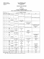
For an exanple of how !o use tables 5, 6,
7 or B to deternine lhe proper sequence of
unloading, assume we have a 16 cylincter
compressor. I! has four solenoids, tvto orl
each end. one solenoid on each end conlrols
2 pairs or four cytinders and the other
solenoid on eech end controls I pair oI
cylinders. l,{e want a capacity viriation oJ
UANTJAL
3W-F
Page 30
SMVICE
Instluction
V/W
COMPRESSON UNITS
FnEoN AND Alll{oNIA
3-3/4 X
3
OPEMTION AND ADJUSTI,,IENI
TABI,E 5
16
CYLINDER
AUTOIIATIC UNLOADER SEQOENCE
TOTAL POSSIBI.E CAPACITY VARIATION FROM 1OO% TO 25%
,
i
(3&4 ?.J)(1r&r2 r5&r6)
i
r@(rar ?ta)(D&r2 1506)
3
3
3
(3&{ ftax
3
3
(3&4
?.4)(rLr2
r@(J}r| fta)9&1o(r1&r2
15&16)
!r!r2 r5.r5)
r5e16)
(3&1' ?!S)9&10([&ra 15&16)
le
(3&r ?.ax11&12 15&16)
3
3
1
9&ro(rr&r2 r5!r6)
rl2(3r{ 7&3)(rrdz r5er6)
1@
3
3
3
3
wil#l
3
3
(3&4
?&3)(r1d2 15ar6)
3
(3!r ?!a)(1r&12
3
rr&16)
r4(11i'l2'r*16)
3
3
3
3
3
{
(3pr ?&8)(1r&r2 rr&16
(u&r2&rrar6)
5
5
5
5
)
n rir'_ i5,16 r
v/t{ colPnEsson
UNITS
SDRVICE IIAI,II]AL
Instruction
FREON AND A.ITIdONIA
3-3/4 X
3l{-F
Page 3l
3
OPENATION AND ADJOSI'IIENI
TT1ALE 6
12 CTLII{)Ef, COIPRISsOR
AI'JOIIATIC IJM'ADIM SEQIENCE
TOTAL POSSIBLE CAPACITl VAIIATION
IS FiOX IO(ft To
$-Il3F
IDcreDents Io Capaciry Aid Unloadins
Sequerce of Cyllnders Ge€ Fid.26)
63-r/3X
I
I
5€6
(re2 566)
2
2
2
2
2
2
2
2
2
2
2
2
3
3
2
3
3
3
3
3
3
3
3
3
(le2
tE2
5€,6
l1612
(lc2
(162 5€6)
(lc2
5€6)
(l€2
566)
5€6)
ll€t2
33-l/4fi
(162 5€6) (76A
(?€a
llel2
?€€
1lcr2
It2
(?€a
(76! trcr2)
ll€l2)
E2
(763 11612)
102
E2
5e6
5€6
tc2
Ir€12
5€,6
E2
llel2
Pairs of Cylinders Inside Parentheses are cortrotled by
tlcu)
E2(764 11612)
IC2
*4
lEl2)
566)
llct2
5€6(7€a 11612)
4
MlE:
5q
66-2/6
One Sotenotd
TASLE 7
a cEIt\'Dm co|@nlssoR
AUTOTATIC UNI'ADING SEQI'EI{CE
IOT,{L POSSIBLE CA?ACITY VARIATION I5 FROI' IOCfi
10 25X
horenents in Capacity And Unloadltrg
of Cyltnders (see Fig. 2a)
Sequence
75%
I
I
I
I
I
tE2
(re2
2
2
2
2
2
2
3
3
566)
t6
E2
?60
2
It2
(l€2 5ed
?6A
(162 566)
{162 566)
7€8
566
7€A
lE2
llot€: Pairs of
25tr
5Cft
7E0
Cylinders lnstde Parertheses are ContoUed by
Otre
Solenoid
TAALE A
6 CILINDIR COIIPRESSOB AU?oI|ATIC UNI'ADINC SEQUENCE
IITAL poSSrBt.E CAPACITY VARTATIO\ IS F[Ol[ IOOS 10 33_1/3*
Incrererts In CaplcjrJ Ard Unloadtnq
of Ctlliders G€e Fiq.
sequence
66-2/&
I
I
le2
2
tE2
tc,2
i(m:
Patls of cyli.ders rnstde pare.thesos are Conrrotled by
Ore Solenoid
3X-1/&
(162 5e6)
5€4
*,1)
V/
COIDRESSOR UN]TS
FREON AND AMMONIA
SERVICE IIANI]AL
Instructioll
3l{-F
3-3/4 X
Page 32
3
OPERATION AND AII'USTMENT
from I0(% to 25% in four sleps; or increnents in capacity of 75% ro \eA a 37-I/2%
to 25%. Looking a! tabte 5 we find wirh
four steps and four solenoids aI 75% capacilyr the control device (therrnostatic or
suction pressure) should acluate the opening of the solenoid cont.rolling the unloading
of cylinders 3 e 4 and 7 E I shown in Fig.
2B. For further rednction to sCPl capacity,
the solenoid controlling cylinders 11 e 12
and 15 6 16 should be energized. AL 37-1/2%
capacity reductionr the solenoid controlling
cylinders I e 2 should be energized and at
25 % capacity reduction the solenoid
l2
OIL
PRESSURE FAILURE SI{ITCH
The Penn Type 275AP10 oi1 pressure failure swilch (see Fig. 16) is an oi1 pressure
differential switch plus a line delay switch.
It operates on the difference between the
suc!ion pressure and oil pressure. When
the conpressor is s!ar!ed, the nornally
ro o
|
@@
[')
\_,/,
6
*
controlling cylinders 9 6 l0 should be
energized. When the ]oad increases the
cylinders will be pu! back into operation
in the reverse order of lhe unloading
CYLTNDERS HAVING A PLAIN
8
CYLINDER
CYLINDER
SLEEVE ARE ALWAYS LOAOEO
SEAL END
rororol
r0)
0t
899
0@
TEE
EE EE
12 CYLINOER
16 CYLINOER
PLAIN
LH
Fiq.
2B
-
ldeihod
@/ 0l
BH
of
Numbering Cylinders and Unloader Designalions
v/w
SMVICE IIANUAL
3l{-F
Page 33
coMPRESSoR UNITS
FBEON AND AMMONIA
3-3/4 X
Instruction
3
OPEMTION AND ADJI]STIIENI
closed tine delay switch is energized. If
lle oil pressure does not build up io lB
psig above the suction pressure in 90
seconds, lhe tine delay switch trips to
stop the compressor. The cornpressor cannoi
be restarted until the reset but.ton on the
control is manually reset. NoTE: l/ait 5
ninutes for the heater t.o cool before dePressirg the reset button.
If the oil plessure rises to above l8
psig differential in apptoxiftately 90 seconds
after lhe compressor startsr the tine delay
heater elenent. is autonatically de-energized
and lhe conpressor continues to operate
nol'm 1ly.
If the oil pressure should drop belorv
l0 psig differential during the running
cycler the time delay heater elenent is
energized andr unless oil pressure retutns
to 10 psig differertial within approxinat.ely
90 seconds, the compressor rvil1 be shut down.
Time Delav - The tine delay device is a
trip-freer bimetal, manual reset type wired
as an integral part of the oil failure
switch. It is faciory adjusted for approximately 90 seconds and should not be changed
in the field.
This unit is conpletely conpensated to
assure uniform
tifting
under
all
anbient
tenperatures. (Timing is affected only
variat ions
i|| voltage),
by
The line delay resistors in the oil
failure switch ate the sane for either ll5v
or
230V
A.C. or D.C. service,
Adiusiments - The oil failure switch incorporales a direct readingr visible calibraled
scale indicating ihe cut-in and cu!-oul
points. The swilch is factory set to cut
out at 10 psig and t.o cut in at 1B psig
above the suction pressure. Changes in the
settings are made bJ adjusting cam,'C"
(Fig. 16) and nut "D",
Turning cam "C" clockwise (viewed fron
lop) raises both cut-in and cut-out setlingsl
and turning cam "C" counter-clocl!.wise lovrers
both settings.
Turning adjusting nut "D" clockwjse
(viewed fron top) lor'rers the cut-ou! set.tingr
and turning adjustirg nut. "D" counterclock{ise raises the cut,-out sett,ings,
SERVICE
GENERAL
Before disnantling a conpiessor for
repairsr observe the following precautions:
(a) Be sure the faulty operation of the
plant is caused by lhe conpressor and
not sone other part of the plant.
(b) Disftanlle only the part of the conrpressoi necessary to corTect the fault.
(c) Never open any part of a conpressor
is under a vacuun; be sute rnere
is sone pressure inside as indicated
by a reading above zero on the gauge.
If the conpressor is opened while undera vacuumr air will be dlawn in with
moisture. This moisture laden air rrrill
conre in contacl with machined parts
which have been exposed to Freon and
rapid corrosion will result. Freon is
an excellent cleaning agent and will
which
(d) In?ernal machined parts of the conpressor such as valvesr pislonsr shaft sealr
crankshaftr etc.r rnust be ionediately
protected frorn the compressoT. Coat
Lhe parr s with oil and wrap them in
clean papeT.
CYLINDEB HEADS
When disrnantling a conpressorr notrce
should be taken of t.he cylinder heads before they are renoved from the housing.
t,o mark each one and
the housing. Also cert.ain heads are equipped with relief valves and lhese heads must
be replaced correctlyr so that. t.he relief
qas passage will line up between the head,
gaskelr and housing. These pressure relief
valves are spring Ioadedr ball check type
which allows the discharge gas to escape
back !o the suction. These valves are set
remove any
to
metal exposed.
it
natural protective coaling
of the iron or steel seaving the raw
it would be
its position on
Before renoving the heads
$ell
psi differential.
open
at
When
reassenbling a head, be sure
250
up with nanifold
firstr
and
ro line
bolt it
v/I|I coupnrssoR uNrTs
SMVICE MNUAL
Instruction
FBEON AND AIII.IONIA
3W-F
3-3/4 x
Page 34
3
smvIcE
snugly before bolling the head
conpressor housing,
to the
To sinplify siocking of reneaal partsl
only the head gasket with the relief Port
is available. lt may be used for plain
heads as well as those with ihe relief valve.
DISCHARGE VALVE ASSETCLY
(Fig,
29)
The discharge vaLve assenbly has a ring
plate type discharqe valve (9) of stainless
steel with a cas! iron valve cage (6). The
valve is pinned by two hardened guide pins
(lD on ihe inside dianeter to prevent
rotalionr and rests on six springs (10)
which are seated in the valve cage. The
discharge valve bolt (13) and self-locking
nut (15)r hold lhis entire assembly intact
so lhat it is easily asseobled to the top
of the suctlon valve p]ate. The correct
lift of the valve is insured in the design
of the cage. Each cage is stamPed wiih the
letler "A" or "F' (Arnnonia or Freon) .
VALVE MUST CORRESPOND TO l'tIE GUIDE PIN
IN THE VALVE PLATE FOR CORRECT POSITION-
ING. This pin prevenls the valve flon
rota!ing during operation.
(b) So that the valve plate with its valve
in place may be inveried for assembly
to the conpressori nake trwo sheet metal
clips as shown by Fig. 31,
(c) Slip the clips through the I.D. of the
valve plate (1800 apar!) and over the
valve so that the springs are conptessed
and xhe valve
ion. one nan nay acconplish this bY
renoving the unloader cover plate and
placing a oooden block between it and
the unloader piston. Tighten the unloader cover plale bolts until the
unloader pins ate depressed or in xhe
lolded position. lf lhe unloader pins
are not depressedr dardage to lhe suction
valve wiLl result when the suction
valve plate bolts are tightened. After
the suction valve Plate bolts are tight'
be sure to renove the wooden block used
to depless the unloader pins. This
procedure is not necessary on Freon
(?) with ,rasher (B) bolts the
discharge valve assenbly in place on the
conpressor suction valve plate.
SUCTION VALVE ASSEiIBLY
Fig,
29
The suction valve assenbly consists of
a ring plate type valve (1) of stainless
streel, six suction valve springs (2), casL
iron valve plate ($r and the cap screws
(4) and washers (5).
corlect ]ift of the valve is insured
in the design of ihe valve plale. Each
valve plate is stamped with lhe leiter "A"
or "F" Gnnonia or Freon).
(a) For assenbly, place the valve plate less
discharge valve cage bottom upr insert
the six valve springs in the recesses
in the plate, and place the ring plate
valve on the splings. A NOTCH IN TIiE
The
recess.
(d) Place the assembled valve plate in
position on the housing with the copper
qasket beneath, CAmIoN: Before replacing lhe low lift Annonia valve plates
on the unloading cylinders, it will be
necessary to nake sure the unloading
pins are dolvnt or in the loaded posi!-
Cap screr,r
Fig. 30 shows the correct position for
the valve cage assernblies when mounted on
the suction valve plates. The four discharqe ports nus! be oriented so that their
center lines will be 45o iron the horizonlal"
This will nean the discharge valve guide
pins beihg in a line perpendicular to lhe
vrrjst pjns and the crankshaft, resulting
ln the least aDount of wear,
is held in its
conPressors,
(e) Tighten the cap screws hand tight and
renove the steel clips !o allow the
suction valve !o snap dolvn inlo posit-
(f)
Tighten the cap screws and assemble lhe
dischalge valve cage.
Il it becones necessary to replace the
suction valve guide pinr order new pins,
&-368PK and proceed as follorrrs:
(a)
Drill
an ]/8ri hole fron ihe lop of the
if not already there.
valvp plate
(b)
Use
out
a
drift pin in this
trhe rvorn guide
(c) Drive in the
pin.
new guide
hole to drive
pin,
v/l{
couPBEsson UNITS
SMVICE I'ANUAL
3l{-F
Page 35
Inslruction
FSEON AND A.II}IONIA
3-3/4
x
3
SERVICE
PABTS
Ref.
LISTI Fig.
Item
No.
I
29
Suction Valve, Ring
PIate
Suctior Valve Spring
Valve Plate g Guide pin
2
3
Freon
Ainnonia
Plate Cap Screw
Valve
Valve Flate Washer
Discharge Valve Cage
4
5
6
Freon
Antnonia
Discharge valve
7
Cage
Cap Screw
B
Discharge Valve Cage
9
Di6charge Valve, Bing
t0
Discharge Valve Spring
Discharge Valve cuide
Washer
Plate
1I
pin
t2
13
Discharge Valve Seat
Discharge Valve Seat
T4
Discharge Valve Seat
Boli
Gasket
Discharge Valve Seat
I3-t5
5,9-15
GUTDE PIN
Fig. 29 - Suction
Nut
Bolt Assembly
Complete Discharge
Valve Assembly
Freon
ABmonia
and Discharge Valve
Assenbly
CAPACITY REDUCTION
The method of capacity reduction rs
acconplished by neans of unloader pistons
which operate from oi1 pressure. When the
machine is not in operation each bank of
cylinders equipped with capacity reduction
unloads conpletelyr thereby eliminaling ihe
necessity of a starting by-pass or a special
motor to oveTcone high starting torque,
Another advanlage of this type of capacity
reduction is its very low penalty on brake
horsepower per ton at partial capaci!ies.
When the compressor is not
the unloader nechanism, which
in
is
operation
operated
DISCBARGE
IHIS LINE
Fig. 30 - Spacing of Discharge Valve
Cages
SERVICE IIANUAL
Instruction
3l{-F
Paqe 36
V/W
COMPRESSOE
UNIIS
FREON AND AMMON]A
3-3/4 X s
SMVICE
cylinder sleeve is locked
housing with a pin (B) to keep it
Each unloader
io the
from rotating out of posit.ion. These
cylinder sleeves (11) are fitted r,Jith a
loose fit so that they nay be renoved in
the fie]d. To renove these sleeves, firs!
renove the unloader pislon cover and remove
the piston and rod carefully so tha! ihe
unloader pislon, under tension frorn the
spring, does not fly out. Ease out the
sleeve. lllhen replacing lhe dylinder sleever
the can ring_(6) nust be turned so tha! its
slo! is centrered under the lift pin at point
h'
i ca.-8
{:*,o
Fig. 3l - Clips Applied to Suction valve
Plate
oil pressure, is in the position shown
in Fig. 32. The unloader spring (4) pushes
the unloader piston (l) and lhe unloade!
by
rod (5) back, thereby rolal-ing the cam rings
(6) so thar the lifr pins (7) are raised
on the cams. These lift pins raise the
conpressor suction valves compressing the
sucLion valve springs. The unloader remains
in this position until t.he compressor is
slarted and the oil pressure reaches approxirnately 30 psi, at which point the pressure
pushes the unloader piston back against the
unloader spring. This motion is transnitted
!o the cao ring $hich rotates and lowers the
lift pinsr allowing the suction valve to
act as a normal valve.
The lift pins (7) are beveled with a l5o
taper on the end riding on ihe can ring (6)
so that the pin wi]l have full contact with
the caft. The lifi pin spring (9) is conrpressed when the cylinder is unloaded and
keeps the lift pin in contact ftith the can
ring nhen lhe cylinder is loaded again.
This spring is kept in place by a ro11 pin
(10) lhrough Lhe lifL pins which also prevents the pin fron rolating so that the
beveled end does not. get out of contact with
ihe
cam.
Fiq. 32 -
Unloader Mechanism Assembly
v/$i
COMPBESSOR UNITS
SERVICE IANUAL
3$l-F
Paqe 37
Instruction
FREON AND A.IIMONIA
3-3/4 X
3
smvrc0
PABTS
Ref.
I
2
3
4
5
6
6
7
I
LISTi Fig.
32
Item
No.
Unloader Pi ston
Hex Head Cap Screw
Push Rod Washer
Unloader Device Spring
Push Bod
ning (Left Hand)
Cam Ring Gight Hand)
Lift Pin (ser of 6)
Can
Locating Pin
9
10
Lift Pin Spring
1I
Cylinder Sleever Bare
Cam Bing Support Ring
Retaining Ring
12
t3
14
6-14
6-14
Roll
Pin
Locking Pin
Unloader Sleeve
Assenbly (L.H.)
Unloader S]eeve
Assembly (R.H.)
A (see Fig. 32), This pin is opposire the
locating pin (8). The exception to lhis is
the inside pair of unloadinq cylinders on
the I and 16 cylinder cornpressors and the
one pair on lhe four cylinder. Locate the
slot below poinL B for these locations,
Before replacing the unloader piston plate
push in on ihe unloadex piston with the
hand and observe both cylinders to see that
ihe unloader nechanisn is working properly.
It nusi be noted !ha! the unloadets are
designated as either right or left hand.
R, H. or L, H. stamped on can ring, Aclua]ly
all parts of the unloadet device are interchangeable with the exception of the cam
rings which have the cams sloped in opposite
directions. The hand is deternined by the
position of the unloader lod in respect !o
Lhe cylinders when one is looking f;om the
end of the conpressor facing the unloader
piston. llhen the unloadels are to lhe left
of the cylinderr lhey are designated as
left-handr and those with the unloaders io
the right are designaied as right-hand,
Fig. 2B shoHs the method of nunberinq
!he cylinders and determining right or ieft.band unloader mechanisms. In orderinq re-
placemen! parts it is necessary io designate
the cylinder nunbers with left or right
hand unloader nechanism.
You will note that the only difference
between t.he L.H. and R.H. sleeve assefiblies
is lhe cam ring (6). It is inportant, howevert when converling a L.H. to a R.H. or
vice versai the lift pins nust be rotated
1B@ so that lhe beveled ends will make
full contact. wilh the cam ring. This cdnversion should only be made in the case of
emergencyr should t,he proper sleeves nor De
innediat.ely available.
At the botton of Tables 51 6, 7 and 8
folrnd the proper sequence for manually
unloading the cylinders. (To unload, open
the relief line valves shown in Fig. 26),
is
PISTONS AND CONNECTING RODS
Install the pistons with connecting ro.lsr
naking sure tha! t.hey ale in the proper
cylinders, The piston rings rnust be free
in the grooves
and
ring
gaps rotated l2oo
from each other to insure best compresslon
and to prevent excessive ojl usaqe. Check
the.wrist pins and the wrist pin ]ocking
springs, Inslall all connecting rod capsr
wilh nurs.finger tight at first; rhen pro_
ceed io tighten each connecling rod cap
separatelyr Match the nunbers stamped on
the rod and cap. Botate the shaft after
each separale connecting rod is tightenedr
to deternine if binding occtlrs.
SllqFT SEAL
The shafL seal is a single, spring
loaded, balanced seal, simple in-design,
a d using no diaphragms, (see Figs. 33 and
34) A casL iron shaft seal collar with
rubber "0" ring is secured !o the crankshaf! by a steel ball and two locking nuts,
ihereby rotaling with the crankshafi. A
carbon shaft. seal ring with rubber ,,0,' ringi
loaded by B sna1l helical springs, is locked
to t.he cover plate by a ro11 pini therefore
llris assenbly is slationary. The lateTal
novenent of ihe shaft seal ring al]ows the
contact surfaces of the carbon ring and
casl iron collar to always be in co[racr.
The iapped corLacr surfacps are separareo
l,y a filn of oil. This oil, s-tighlly above
crankcase pressuter is supplied by the oi1
v/$
SERVICE MNUAL
Instruction
cOwRESSoR UNITS
FREON AND AIII1IONIA
31,{-F
3-3/4 X
Paqe 38
3
smvIcE
Fig. 33 -
Exploded View
punF and lloods the cavity bel$een the cover
plate and bearing head. The two rubber
"0" rings perforn an inportanL funclion in
sealing off possible leak paths along the
shaft and through the cover plate so they
must be carefully handled and properly
applied.
Seal Leakaqe
The shaft seal cover plat.e is fit.ted
an ell to lead any oil which may pass
through the seal to a canr so as to keep it
alvay fron the motor or belt whee].
of Shaft
A compressor in autonatic operalion, or
any conpressor on startingr nay leak up to
20 drops of oil per ninute during the first
minute of running, but should reduce to
lightness and normal oil drip in a shor!
tine. The seal should not be condemned for
this actionr it. is caused by falling pressure and formation of gas in lhe oil chanber
of ihe seal.
}lith
rate of leakage and condition of the
oil fron the seal drip indicaies the
effect.iveness of the sea]. In operation,
lhe shaft seal surfaces should pass enough
oiI to assure a film between. Five Lo ren
drops per riinute oil drip can pass thrul
either because of too greai pressure (seal
iension) or too snrooth surfacesr the surfaces roughen thenselves until an oil film
can be retained, and then start to weat
snooih again. If the seal has roughened
itself! the first oil out of the drip may
be darkeri but clear clean oil shouLd cone
out after about 2 days running. If the oil
continues to appear darkr then the seal is
being scoled either by $it or scaler or a
crack on the collar surface is shaving lhe
carbon ring. Unless lhis stops wiihin a
week br l0 days and drip relurns to normal,
the seal wjl] have to be replaced or re"The
paired before
failure
<iccurs,
Seal
PARTS
LISTi Fig.
34
Item
No.
I
Quan.
Part
I
I
Cover Plaie
Hex Head Cap
Shaft SeaI Collar
Shaft Seal Ring
5
I
I
I
6
I
7
0
I
2
3
4
I
I
6
Cap Screws
6
Washers
I
10
2
12
14
"0" Ring 3-I/4" O.D.
"0" Ring 4-1/8" 0.D.
Helical Spring
Bearing Head
Gasket 1/16"
Locking BalI
Lockidg Nuts
RolI Pin
Thrust Besring
1
9
1l
Screws
V/W
SENVICE MANUAL
COMPRESSOR UNITS
Instructi on
FBEON AND AMIiIONIA
3-3/4 x
3W-F
Page 39
3
SERVICE
If tle leakage is nornal wilh the compressor running lhere should be no leakage
during shutdown,
Liquid in the crankcase oil will cause
boiling and foaming or falling
pressure. The oil in the seal chamber nay
foan out faster than i! can be replaced,
cansing dry surfaces and carbonizing of the
oil on lhen. if ihey are not scoreo loo
severely, t.he surfaces rvill clean lhenselves
of the carbon and lrear !o tightness again.
cxcessive
The shaft seal is a flooded type seal,
lherefore, it is necessary to have the shaft
seal oil space conpletety filled wit.h oil.
This is autordatically acconplished during
continuous or intermittent operation but
during prolonged shut. down periods it. will
be necessary to insure a flooded seal before
srarl
up,
Seasonal operaied compressorsr should be
watched carefully for shaft seal ]eakage
during shutdown. An emply quart can should
.r;PtPE PLU3
OILFROM SEAL CAVI'TY
cAPSCREWS
@
LOCKWASHER
@
caP scREw @
3r'o.D'o"
RrNG(s)
+'2 oo. "o" ntl!o@
LocKrNG NUTs @
RoLL PrNO
LocKtNG BALL@
OIL DRIP OUTLET
srnrrcs@
eure@
sxarr sear nrro@
HAFT SEAL
coLLARO
THRUST BEARING @
BEARING HEAD GASKET@
L TO BEARING
Fig. 34 - Sectional View of Shaft
Seal
v/[{ cowREssoR
SERVICE MANUAL
Instruct.ion 3W-F
Ll,lrTs
FREON AND AII$IONIA
3-3/4 x
Page 40
3
SERVICE
top of the cover plale and then rer0ove
ihe cover plater and shafi seal ring
as one unit Gee Figs, 34 and 35)
be placed under the seal drain tube during
the off season. Before lhe conpressor is
slarted for its nornal running periodr the
can should be checked to delernine the
afiount of seal leakage.
(d) Examine the running faces of the shaft
seal ring and the seal co]lar for diri,
gritr scratchesr cracks or excessive
An equal quanlity of clean oil should be
charged into the shaft seal by a hand oil
punp atiached io the oi1 charging valve.
(e)
Replacinq Shafi seal
replacing.
If the ]eakage of the seal is
excessive,
the seal should be replaced. To replace
the shaft seal proceed as follows:
(a)
(c)
(f)
the compressorr close stop
valvesr vent crankcase !o alfiosphere
and renove the beliwheel or flexible
coupling hub fron the crankshaft.
Pump down
(b) Loosen the covet plate cap scle$s io
allow the oil to drain fron the seal
cavity.
Bemove
PARTS
Ref.
lhe oil lines fron the side
LIST, Fig.
ancl
the seal ring and B sprinqs fron
the cover plate.
Remove
the two ]ocking nuts, the seal
collar and its locking ball. Do not
pry from t.he back of the seal collar.
Use the groove provided or jack it off
with the bearing jack screws. (See
(9./ Remove
Thrust Bearing
35
Uain Bearing Pin
oil Punp Drag Crank
Main Bearing Head with Plugs
l{ain Bearing Head Cap Screw
Pressure Regulating valve
valve Spring
Valve Cap Gasket
Valve Stern Packing
valve Check Ball
Valve Body Fibre Gasket
Valve Body Copper Gasket
5
6
6a
6b
6c
6d
6e
6f
ll
oil Pump Insert
"0" Ring Packing
oil Pu&p Insert Cap Screw
13
Lockwasher
0i1 Pump Gasket
9
t0
t2
15
10, 11, 12,
136
14
oil Punp
0i1 Punp Cap Screw
oil Pump Kix
Seal End
entire seal cavity.
liain Bearing
1
-
for
procedure)
(h) Clean a]l parts to be re-used in an
appToved safety solvent as well as the
No.
2
3
4
9,
If the faces show any of the items just
rnentionedr the worn part or parts need
Fitting
V/W COIIPRESSOR UNITS
SENVICE IdANUAL
Instruction
FEEON AND AIdI{ONIA
3-3/4 X
3
SERVICE
tiq.
35
-
Main Bearing Head and
3l{-F
Page 41
oil
Punp Assenbly
V/W COTFRESSOR UNITS
SERVICE IIANUAL
Instruction
3W-F
FNEON AND AMMONIA
3_3,/4 X 3
Page 42
SERVlCE
9/64" hole in the cover p1a!e using a
micromeLer depth qauge, This dinension
NoTE: Even carefrl examinalion may
fail to detect culs in the "0" rings'
80 ehen repairing a shaft seal it is
good practice to replace lhern.
(i)
(j)
Be certain at this time that the clearance on the thrust bearing does not
exceed .006rr. Excessive shaft end play
can be responsibLe for seal failure.
(See CflECKING SmFT THnUST CLEARANCE)
Place the 3-1/4" 0.D. "0" ring (5) in
its recess in the shaft seal collar (3).
Pull the crankshaft all the way toward
the seal end and install the shaft seal
collar (3) naking sure that it is locked to the shafi by the locking ball and
its thrust side is bearing against the
shoulder of the shaft. Apply the oiiginal collar n t and locking nutr Pu1]ing them up tight, Be cerlain the
thrust clearance remains the .003".006" originally a1lowed. Push the
shaf! toward the punp end,
should be .612
+/-
,012.
(p) Beconnect the oil lines to the side
top of the cover plate (l) .
and
(q) Since this is a flooded type seal, it
qrill be necessary !o fill the seal oil
cavity wiih oi1. Charge one quart of
oil into lhe seal-oil charging valve.
(r)
Be sule atl oil line joints are properly
nader lhen reassenble the coupling or
belt
vrheel.
The compressor
xion.
is
now ready
for
opera-
a close check on the seal for
a shor! period. Do not be alarned if there
is ho sign of oil drip at all for the shaft
seal leakage is relatively low. 0n1y 10
to 15 drops per day night be observed at the
elbow (9) on the face of the cover plate.
piece of drain tubing may be attached !o
A
(k) Place cover plate on a horizontal surface
the
elbow if desired.
with the spring holes face up. Place
(7)
in their sockets.
the B springs
(D
P]ace the 4-118" 0.D. "0" ring (6) in
its recess in the shaft seal ring (4)
and place this assenbly in the cover
plate (l) being cautious no! to cut or
jan the "0'r ring. Be sure that the
locking pin in the cover plate entets
its proper hole in the shaft seal ring
and ihat the springs are properly
seated. Depress the shaf! seal ring to
be sure tha! it is free to move. Place
a l/16" beaxing head gasket (B) on the
cover plate assembly.
the contaci surfaces of the
shaft seal collat (3) and shaf! seal
ring (4) are free from all foreign
(m) Make sure
particles.
Apply
OIL
REPLACING TI]E
PUMP
oil punp (Fig. 35) is designed so
that all moving parts are housed in a
The
single unit.
To replace the
follo,{s:
(a)
Punrp down
oil
purnp Proceed as
the compressorr close stop
valves and vent crankcase
(b)
to
almosphere.
pump (14) by renoving
(15).
cap screws
(c) Dismantle oil pump assenbly using an
Allen wrench to back out cap scret'rs
Reflove
the
oi]
(11). Remove in turn the insert, rotor'
idler, idler carrier crescentr spring
oil to lhese surfaces.
(n) Assemble the cover plate assetlblyr with
gasket in posilioni to lhe bearing head
using the cap screws (2), Draw lhe
bolts up evenly and tightly.
(o) After rhe assenbly is cornplele measure
'X" (dist.ance fron outside of cover
plate to shaft seal ring) thru the
Keep
and ba11.
(d
Remove
the "0" ring (10) and the
crank (3)
drag
.
(e) Clean and oil all Parts.
(f) Renew parts as necessary reversing the
above steps. Ilse care not !o danage
the "o" ring.
v/w coFREssoR uNrTs
SERVICE }IANUAL
3W-F
Instruction
FREON AND AIIMONIA
3-3/4 X
3
Page 43
SERV]CE
(d
MAIN AND TIfiUST BEARINGS
A11 nain bearings
of aluninum alloy.
are sleeve type
Support lhe shafr wirh blocks inside
the crankcase and remove the bealing.
and
this, renove the six cap screws
fron lhe thrus! bearing (12) and use
these screws in the tapped holes in the
bearing to jack it out.
To do
The thrust bearing is designed to take
the shaft thrust. in both directions. Radial
oil grooves are nilled on both ends for
lu'Dricating the thrust surfaces.
lqiq
B€artnq
-
Pump
End (See
Fiq.
This
35)
The following procedure is reconunended
when replacing pump end main bearings:
In jacking off the seal collar, take
up the slack and then lap the end of
the shaft, Repeat until t.he seal collar
nay be pulled off. Do not force trle
jack screws which would pull t.he whole
shaft and spring t.he connecting rods.
(a) Arrange blocking under shaft in crank-
(b) Disconnect the oi1 lines at the oil
pump encl.
(c)
Remove
(d)
Remove
(e)
the oil pump assenbly and the
bearing head wilh the bearing in p1ace.
the sleeve bearing fron lhe
bearing head.
(^) Clean aII parts with approved safety
solvent. Blow out oil ways with dry
air or nitrogen.
NoTE: Do not use
ing parts,
linty
rags
for dry-
(f) Install a new bearing into the bearing
head and reassemble to the compressor.
Pin e) keeps bearing fron turning.
(s) Inspect. the
oil
pump
(f)
l.
neplace lhe bearing headt eithout the
aluninun bearing in place.
2.
Wit.h the bearing head
assenbly and assen-
oil piping and renove
the blocking under shaft.
(a)
Re.nove
(b)
Remove
Seal End (see Fig.
the flywheel or coupling
34)
hub.
the shaft seal assenbly and the
shaft seal collar lock nuts fron the
shaft.
tcJ
the shaf! seal collarr making
sure lhe sleel ball for locking the
seal collar to ihe shaft is not, lost or
Reinove
not install a bearing into ine
housing. To prevent possible danage to
bearing the following procedur:e is
Do
recorunended:
(h) Connect up the
-
the bearing head and clean all
part.s with cleanirq solvent. Do Nm
use raqs for WIPINGi BLoW out iroisiure
and foreiqn matter with dry air or
Renove
nitrogen,
ble it !o the conpressor.
Thrust Bearing
wiII force the seal collar loose.
not to lose lhe locking ball
Use care
(9) .
in place slip the
aluninun bearing over the shaftr into
the housing. Care should be exercised
to prevent scoring or upsetting netal on
the lhrust ends and load surfaces.
Upset metal on the beaxing surfacesr and
high rotating shaft speeds nigh! start
scoring of the bearing surface and shaft.
journal. Be certain the oil hole in the
bearing is at the botton. (nemove blocking fron under the shaft) .
3. With washers and cap screws tighten the
bearing in place against the seat.ing
surface.
4.
The shaft. seal collar with the "O" ring
are assembled and installed on the shaft
wit.h the steel locking ball in p1ace.
flisplaced. (See Replacino Shafr Seal
5. Use the Spanner wrench to lock rhe shafr
for procedure to reoove lhe seal collar,)
seal col1ar nuts,
V/W COIIPRESSOS UNITS
SERVICE I'IANI]AL
Insxruction 3W-F
FREON
AM
AIIIIONIA
3-314 X 3
Page 44
SERVICE
6.
Replace the seal and lhe
(or coupling) .
belt
wheel
Checkino Shalt Thrust Clearance
type bolt for exPanding and locking bearing
into posilion in the housiilg bore. (See
Fis.36)
The follo$ing procedure is
recom€nded
for replacing the center nain bearing in
(a)@
the inside thrusi surface. Pull the
shaft toward the drive end,
(b) l{easure the clealance (see Fig. 34)
be!$reen lhe thrust side of the seal
collar and aluininun bearing thrust face
with the feeler gauge, ltinimun cleaiance .003'r, naxioun clearance .006".
(c) Alternate
method for checking Thrust
clearancea
Mount dial indicator against the end of
the shaft and pry 6haft toward puop end,
set dial indicator at zero and pry shaft
toward drive end and record the dial
indicalor readings. They should be
(.003") to (.0069. If exceeded insrall
nea bearingt
Center lfain Bearinq 12
e
16 Cvlinder (only)
llade of aluminun a11oyr with spider type
shell, cas! in one piece and split vertically at the top and provided flith wedge
Fiq.
36
-
the 12 and 16 cylinder conpressor:
(a) Drain the crankcase oil and disconnec!
ihe oil piping.
(b) nenove the iop heads, suction valve
cages, suction valve plates and suciion
valve rings.
NmE: Do not drop suction valve springs
in cylinders.
(c)
Remove
PAITS
Ref.
I-8
3
6
the connecling rod caps.
LIST, Fig.
No.
36
Iien
Bearing Assembly
Center
Bushing, Center
Bearing
Donrel Pin, Center
Bearing
Center ltain Bearing (12 and 16 Cylinder only)
v/w colPBBssoB utllTs
SERVICE }IANUAL
3W-F
Instruction
FNEON AND AUI'TONIA
3-3/4 X
Page 45
3
SENVICE
center main bearing nakinq suTe connecrions are tight,
the pislon with connecting rod
asseroblies and replace the connecting
rod caps to prevent mix-up.
(d) Renove
flhen replacing one nevr eraln
bearinqr it is important to inspect all
main bearings to deternine the anount
of aear. The changing of one nain bearing may require the changing of al1
oain bearings to maintain accurate shaft
WARNING:
rhe pump end bearing head assenbly with oil pump,
{e) Remove
(f)
Rernove
the couplinq hub fron ihe shaft.
(s) Renove
the shaft seal assenbly.
(h) Renove
head.
the drive end bearing and bearing
(i)
Reflove
(j)
Remove
aIignEent..
(r)
the tapered wedge boll from lhe
top of the center bearing to free the
bearing fron t,he crankcase bore.
Proceed to re-install oii punp assembly,
check the thrust clearance .003" to
.006". i4sta11 the shaft seal assemblv
and adjust the tension.
ihe cenler fiain bearing dowel
pinr covered by l,/2" pipe pluq, from
the side of the conpressor.
(k) The cente! main bearing, with lhe crankshaftt must be removed frorn the conpressor as an asseDbly. It requires two
men to nove the shaft out of the
compressor housing, through the punp
end.
(1) Rest
rnove
Fig.
the shaft on wood blocks and rethe center bearing from the shaft.
(nt Examine and clean shaft journals and
crank pins. llone where necessary to
sr0ooth scratches or scored areas if any.
PARTS
Ref.
I
2
Wilh the center bearing and shaft in
proper location in the compressor bore
and aligned wiih the doi,el pin holei
insert the dowel pin and tap lightly.
Replace the 1/2" plug using lirharge
to close access ho1e.
5
(q) Tighlen the wedge
bolt through the
center main bearing to expand the bearing inlo the housing bore.
NoTE: Connec! the
oi] line to
feed
No,
3
- Oil Level Sighr Glass
Fig.
37
Iten
oil
Gas
Inst,all a new firain bearing to center
journal on the shaftr and replace the
shaft with the bearing mounted on the
shaft into the conpressor.
(p) Replace ihe nain and t.hrust bearings,
and pull all cap screws tight.
LIST
37
Sight Glars Fibre
ket
0i1 Sight Glass
oil Sight Glass Rubber
Packing
0i1 Sighi Glass
Packing Gland
oil Sight Glass
Cap
Screw
oIL LEVE SIGHT GIASS (Fig.
37)
The crankcase oil ]evel sight gless is
located al the oil pump end of ihe conpressor to indicate lhe oil level. Correct
oi1 level is half way up lhe bullseye,
l{he, installing the sigh! glassr extreme
cale hust. be used to centet the bulb with a
feeler gage and draw the cap screnrs evenlyr
Lo prevent, undue
breakage.
strain and resulting
v/fl
SERVICE IANUAL
hstruction
cotPREssoR uNus
FNEON AND AMIIONIA
3l{-F
s-zlA x
Page 46
g
SERVICE
HOUSING
"3x,i5.€"o"
""1.3i:"
cf
a
PARTS
Bef.
I
2
LIST, Fig.
Fig, 38 - suction Strainer Assenbly
(c) Remove the bolls (B) fron discharge end
strainer covex (6). NoTE: Do not renove the nut located in the center of
38
Iten
No.
this
Strainer Screen
Strainer Bag
(d
Cover-To-Stud Ga sket
Stud
Discharge End Cover
(e) If it is necessary to replace trhe
slrainer scleenr renove the cover nutl
(4r
3
4
Betaining Spring
7
Gasket
Cap Screl{
Suction End Cover
9
cover, gasketr slud and lockwasher
rnake
To renrove the slrainer assenbly from the
discharge end of the following procedure is
38)
(a) PuEp out lhe conpressor.
Remove
any tubing that nay be
cover.
of the stTainer
NoTE: UPon reassembly
sure the cover-to_stud gaskei is
in its
(f)
Fig.
the strainer assenbly from the
5, 6 and D.
The strainer assenblies can be removed
fron the suction or the discharge end of
the 4, 6 and I cylinder compressors, 0n
the 12 and 16 cylinder lhey can be removed
in one way, from the discharge ends, NoTE:
llhenever possible renove lhe strainer assen
bly fron the discharge end of the 4, 6 and
I cylinder conpressors.
recornmended: (See
Rernove
conpressor housinq,
SUCTION ST?AINER
(b)
cover.
ProPer P1ace.
the slrainer be sure it
enters lhe hole in the conpressor
housing. Forcing lhe strainer in by
use of the cover cap screws will collapse it.
Belt driven 41 6 and I cylinder conpressors may presen! sone difficulties (because
of the fly"heel) in the removal of the
strainer assembly from the discharge encl.
when replacing
the strainer fron the suction
to Fig. 39 and proceed as follows
(a) Punp out the cornpressor.
(b) Renove the suciion end sltainer cove!
To rernove
end refer
(9) .
in front
(c)
lhe discharge end cover nuii
(6)
and cover-to_stud gasket (4)'
cover
Renove
V/W
COI'IPNESSOR UNITS
SERVICE iIANUAL
Illstruct.ion
FBEON AND AMMONIA
3-3/4 X
3
3W-F
Page 47
SERVICE
CAUTIoN: The cover-to-st.ud gasket (4)
musl be removed befole lhe sirainer is
puIled through the compressor housing
or il nlay be lost itside the conpressor
suction compartrnent.
IIANUFACTIIBING TOLERANCES
Dian.-Top
-Botton
Wrist Pin Hole
(d) The strainer screen can now be removed
Irom the suction end of the conpresso!
housing.
(e)
insert lhe slrarnel
screen ln the suction end of the
compressor housing, afLer i! appear!
at the discharge end atiach ihe cove!to-stud gasket (4), discharge end
strainer cover (6) and the cover nu!.
Upon reassembly,
(f) Bolt
both end strainer covers (6 and 9)
conpressor hou sing,
to the
,001
- .000
I,O000 + .0003
- .0000
+
.0005
.0000
1.0000
+
.0000
,0003
lllrlst Pin Hole
1.0005
+
Crank End Hole
2.3760 +
Cxank End Width
.87450
,0003
.0000
.0005
.0000
.0005
SeaI End 6 Center
3.25d0 + .0005
Pump End
2.6270
Crank Pin
2.3750 + .0005
Dian,
st Pin Diam.
CRANI(CASE FLOAT VALVE
An installed view of lhe crankcase float
is shown by Fig. 39.
.OOb
3.?500
Cyl,
Wxi
3.?41 t
3.745 +
_
-
_
-
+
valve
l]ltdth
4 Cy],
Between
@12 Cyl.
Bal6 cyl..
Cheeks
Fig. 39 PARTS
Crankcase
LIST, Fig. 39
It
,6005
1,763 1 .oo2
2.640 t .o02
3.515 : .002
Floal Valve
SeaI End e Center
Pump End
No.
;
+ .0005
- ,0000
2.6315 + ,0005
3,2555
-
en
.0000
I
Float Ball
2
3
Valve Body
Floal Lever
REPLACEIIENT PABTS
4
5
Pipe Nipple
6
7
Pin
Pin
The cornpressors have a factory nuftber
staoped on lhe conpressor houslng.
3/4" ova] F]anges,
gasket, bo1!s A nuis
1-8 Float Valve Assetub]y
8
The Jactoly numbet is slanped on top of
the compressor housing direotly above ihe
suction conneciion on 4, 6 and B cylinder
V/l{
CO}FBESSOR UNITS
FREON AND AMI',IONIA
SERVICE MANUAL
Instruction 3W-F
Page 4B
3-3/4
x
3
SEBVICE
The factory nunber is stamped on lhe
compressor housing direc!ly above the
publicity plate (left hand side facing lhe
seal end) on the 12 and 16 cylinder compressors,
l{hen ordering repleceften! parts for any
conpressor be sure t.o specify the following:
(a)
Name
of part.
(b) Part
numbei..
(c) Facxory
number
ol serial
number of
conplessor.
(d) Quaniity of parts required.
REPAIB PARTS STOC( LIST
Table
9lists
the
of repair parts that
!o
should
enable good service on these compressois.
quantity These quantities are based on the nunber
be held in stock conpressors installed.
reconrnended
of
TABLE 9
complessors Installed
Ito
Conplete Seai Assen.
-
15I
ll
l0
3-
0iI
Bearings-MatnGTblust
Cente! Bealinq Assy.-12 g 16 Cyl.
ihin e Thrust Deatinq Head Gaskeis
Discharge ilanif oId Gaskets
Hand flole Cover Gaskets
1.20
Form 180,20-Nl
500 2a0
l0
l0
IO
l0
10
l0
5
5
t2
l6
3
4
2
6
I
I
4
12
12
24
3
I
la
I
L2
.-.
PPC
7
7
fiings
Suction 6 Disch. Valve Assenbly
Suci. € Discb. Valve Rinq Ptates
Suction valve Pldte G3sket s
Code: S{N)
s(N). Int,
26 Ard Up
5
5
3
Connecting Bod Assenbly
Ventilared
25
fli{
2 Sets
l
36
IE
t6
CENTRAL ICE MACHINE COMPANY
Refrigeration Supplies
ToLL FREE Boo-228-7213