1
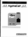
HudraCat
HYDl?A&#ASREZ.
Corporation
I
1
I
I1319W HydraMaster Corp.
Printed in U.S.A.
ignition ....................................................................................................27
Cooling System .......................................................................................27
Exhaust System .......................................................................................27
Air Cleaner ...............................................................................................27
Batie~ .........................................................................................................28
Periodic Maintenance Stiedule ................................................................29
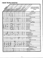
Engine Trouble Shooting ......... .. .... ...................... ...... .................. ...... ......3o
GENERAL INFORMATION
Howlhe System Works ..............................................................................2
Spare Parts Recommendation ..................................................................2
Machine S~cifi~tions .............................................................................2
Warning and Caution .................................................................................2
HowtoOrder ..............................................................................................3
PatisOrders ..............................................................................................3
One Final Note..........................................................................................3
Purchaser’s Responsititi~ ........................................................................3
Sales Representative’s Responsitili~ ......................................................3
TwckSelection ..........................................................................................4
TmckPre~ration ......................................................................................4
Tmck Pre~ration illustration .....................................................................4
Placementof Unitin Vehicle .......................................................................4
Machine installation ...................................................................................4
Propane Tank Location .............................................................................5
Hard WaterArea Map ................................................................................5
WaterSofiener ..........................................................................................5
Wastewater Disposal AdviwW ..................................................................6
Mactine A~ustments ................................................................................6
OPERATING INSTRUCTIONS
shdup
Maintenance Procedures ........................................................................32
Overall Care of Unit..................................................................................32
Maintenance Logs....................................................................................33
Warranty Information ...............................................................................36
Warran~Pro~dure ................................................................................36
Limited Warranty Plan.....................................................lnside back cover
LIST OF ILLUSTRATIONS
Plywood lnstallation(ontwck &d) ..............................................................4
AstiotudandRoof Vent...............................................................................4
Machine XeDow Cleats ...........................................................................4
~chine Configuration ...............................................................................5
Pro~neTankPlumting .............................................................................5
HardWakrMap .........................................................................................5
WaterSofienerHook.up .............................................................................6
pHChati .....................................................................................................8
CleaningStroke Procedure ........................................................................8
Chemiwl System Wring ............................................................................9
WaterFlow .................................................................................................9
Chemical Proportioning and Level Control..................................................9
WandValveAssembly ..............................................................................lO
JetAswmbly ............................................................................................lO
WandAswmbly .......................................................................................ll
Wand Valve Stem Aswmbly ....................................................................ll
By~ss Valve Aswmbly ...........................................................................ll
Vacuum Flow............................................................................................l2
Vacuum Tank RlterBags ..........................................................................l2
BlowerLubPofi ......................................................................................l2
Vacuum Blower Motor Lubrication ............................................................l3
RlotBwnerAdjustment ............................................................................l5
Model 290 Exploded Mew.......................................................................l7
Pumping ~ction Cubway .......................................................................l8
HydraCat Electrical Diagram ....................................................................22
BasicUmensions. P224 ..........................................................................23
Basic Dmensions. P220..........................................................................23
OIMmsi~ ..............................................................................................25
OlfilterLoMtion ......................................................................................26
P220CmnkMWBreather ........................................................................26
P224CmnkMWBreather ........................................................................26
SewicingS~rkPlug ................................................................................27
ArCleanerAswmbly ...............................................................................28
SWcificGravi~Test .................................................................................28
BatieqCaMeConnection .........................................................................28
& PRECAUTIONS
.. ....... ....... .............. .................. ....... ....... ....... ....... ....... .. ..... ............6
Shut Dom .................................................................................................6
Cautions and Warnings .............................................................................7
Freeze Protection ......................................................................................8
Alternative Protection Using Anti.Freeeze .................................................8
Cleaning and Chemical Precautions ..........................................................8
Cleaning Stroke Procedure/Over.wetiing .................................................8
Water and Chemical Flow Operation .........................................................9
Chemical System Maintenance .................................................................9
Chemical Tank Trouble Shooting Guide ..................................................lQ
Water Flow Trouble Shooting Guide ........................................................ll
Vacuum System Information ...................................................................l2
Vacuum Tank filter Bags.........................................................................l2
Vacuum Blower Wanan~ ........................................................................l3
~,,..:VacuumBlower Lubri~tion .....................................................................l3
Vacuum Blower Trouble Shooting Guide .............................................%--14
...
Heating System Information .....................................................................l4
HeaterOperating lnstmctions ..................................................................15
HeaterTroubleShmtingGuide...................................................................l5
CatPump Mode12900prating lnstwctions ............................................l6
Cat Pump Wman~ .................................................................................l6
Mode1290PartsList .................................................................................l7
General Information for Cat Pump Repair................................................l8
Servicing the Valve Aswmblies ...............................................................l8
Servicing the Pumping Section ................................................................l9
Servicing Sleeves and Seals...................................................................l9
Servicing Crankcase Section ..................................................................l9
Cat Pump Trouble Shooting Guide ..........................................................2O
LIST OF PHOTOS
HydraCat (kontview.features labled) .......................................................7
HydraCat(sidetiew. featureslahled) .......................................................7
CatPumpMode1290 ................................................................................l6
Semicingtie Pump...................................................................................l9
Onan Performer Gasoline Engim .............................................................23
Sparlr Plug Diagnosis ...............................................................................27
HydraCat Electrical System .....................................................................22
Onan Performer Engine SPCS . .......... ...... .......................................... ....23
General Information about Onan .............................................................24
ENGINE MAINTENANCE ........................................................................25
Oil System ...............................................................................................25
1
GENERAL UWWWIATION
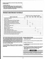
MACHINE SPECIFICATIONS
T’hw manual contains installation and operation instructions as wII as information rquired tar proper maintenance, adjustment and repair of this
unit. Since the first and mast important part of repair work is the correct
diagnosk of the trouble, a general troubleshooting section and component
manual troubleshooting charts have fxen included for your convenience.
‘RAME: 2~ W, 59 L, 3& H. Steef with baked-on epoxy finish.
VEIGWE HydraCat 4.0:630 tbs. (dry ‘might)
HydraCat 4.5:750 Ibs (dry weight)
;OWUNG: Steel with baked-on Epoxy finish.
IMikea garden tractw, Iawmnower arcement mixer, all having one or two
functions 10 fwrtarm, thebuck-mounted carpet cleaning plant has many
functions to pwform simultaneously.
NGINE: HydraCat 4.0: P22020 BHP Onan
HydraCat 4.5:P22424 BHP Onan
GNfTfON: Electronic, Keystart.
* Engine has to run at a consistent RPM.
‘ Vacuum has ta pull air and d@ water bad from cleaning site.
Waler pump provides stable pressure at proper water flow for cleaning.
*Chemical has to be injected into the water stream at the
right cmcentration.
* Heater must maintain proper hsat.
* Vacuum tank must store dirty water until drained.
ii-PRESSURE PUMP: Tri-Plex piston -- Cat 290- 3.5 W%!
-1200 PSI -- @ 1200 RPM.
●
fACUUM BLOWER: HydraCat 4.0: 4ML
HydraCat 4.5: 4LL
Sutorbuift W/l 2 HG Safety Relief.
HOW THE SYSTEM WORKS
:HEM[CAL SYSTEM: Electro-mechanical, meter Conlro!l@d.
The water system takes incoming water at tap (low) pressure, combines it
wilh chemicals from the chemical system and pumps it under pressure
through theheatingsystern, anctouttothec]eaning tool. After being sprayed
into the carpet, Ihe water/chemicaf/soil solution is extracted by the vacuum
system and returrwd to the waste recovery tank.
WATER: Propane fired, thermostatically controlled (180,000 BTU).
There is no guess wrk in the manufacture of these highly advanced
cleaning pfmts.There must also be no guess work in preparing it to get the
job done in the field. h is the purpose of this manual to help you prqwty
understand, maintain and service your cleaning pfant. Follow the directions
carefully and you will be rewarded with years of profitable trouble-free
operation.
?ECOVERY TANK: 70 gallon aluminum, Epoxy finish.
It isimperatfvethat nw$eclfonbeoverlookedwhen
of this equipment.
NSTRUMENTS: 0-1000 High pressure gauge, Temperature gauge,
/acuum gauge, Hour meter, Chemical flow meter, ignition key, Start and on
ndicator fights, Pump clutch switch, Circuit breakers.
;LEANING WAND: Stahless steel with heat shield, Grip and replaceable
racuum fips with stainless steel solution valve.
+f-PRESSURE HOSE I/& High-temperature linecflvin~ covered, Hose
ated to 1250 PSI.
preparing for operation
IACUUM HOSE: 2’ reinforced, 1 1/2’ reinforced.
STANDARD EQUIPMENT: Power conso!e, Sound suppression Packagq
Electric Pump Clutch, Water heater, Vacuum Recovery tank, Carpet
cleaning wand, Chemical jug, Chemicafjugholder, Chemkal@gfill line, (lp
eration manuaf, 150 ft. 2’ vacuum hose, 10 ft. 1 1/2” vacuum hose, 150 ft.
Super-flex solution fine, 10 ft. drain line, 50 ft. water supply line, ~
!d! Freeze guard system, Battery box withholder, Vandeca! package, Fuel
system kit, Installation kit.
SPARE PARTS
RECOMMENDATION
Because your truck-mounted unit is capabfe of generating several hundred
dollars Wr day, down-time on the unit can be very expensive.
In order to minimize such down-time, it is strongly recommended by the
marwfacturcx that PU pumhase and keep in your truck the following spare
palls:
PART NO.
078-015
4178-(119
0ESC13fPTKIN
Flow meter kit
Wand vafve dunger kit
Wlf4XJ4
Pressure bypassvafve kti
Spray @ W06E
Recovwv tank fitterbag
cat 290 short cqp kd standard
076-005
048-029
078-001
078-004
048-023
0624W0
052-051
052-052
a52-a53
106-015
010-021
f%t 290 hoi CUPkit (~ tionat)
Screen, qarden hose
440 Mafe quick conned
440 Femete quick conned
660 Male quick conned
660 F@mafequick mned
Ermine@plug
HydraCalpump drive belt
ADDITtONAL EQUIPMENT, HYDRACAT4.5: Oversize air handling package, High-output component power pack, Super dual silencer system,
electronic tachometer.
WY.
1
1
1
1
The manufacturer uses this symbol throughout We rnarwai to wwrr
Qfposslbie injury ardt?alh.
2
1
1
6
1
1
1
1
This symbol is used 10 warn of possible ei@gme?rMdamage.
2
1
2
HOW TO ORDER PARTS
PURCHASER’S
To obtain a proper diagnosis of your malfunction, and to order warranty
replacement parts, it is important that you proceed in the following mannec
PRiOR TO ARRIVAL OF UNiT
1. lnstali 5/8” extenorplywoodflooring in vehicle and cover with artificial turf.
2. Have beiiy mounted propane tank installed on vehicie. Tank must be
propane vapor type.
1. Call HydraMaster Warranty/Service Department at (206) 775-7275.
2. Give the Warranty/SeM”ce representative the following information:
A. Name of your company and your address.
B. Equipment model (i.e. HydraCat, Bobcat 2, etc.).
C. Date of purchase.
D. Hours on the unit.
E. Serial number of unit.
F. Name of person authorized to order parts.
G. Salesman unit purchased from.
H. Description of malfunction.
1.Pressure readings on high pressure gauge with wand turned
on and off.
3. If warranty replacement parts are needed, please specify method of
shipment desired. NOTE: All replacement parts are sent freight collect, via:
A. U.P.S.
D. Air Express
B. Air Freight
E. Auto Freight
C. Air Mail
4. Do not give malfunctioning parts to a HydraMaster sales or service
representative. All parts must be returned dlrectfy to HydraMaster,
Freight prepaid.
RESPONSIBILITY
3. Purchase heavy duty 42-60 amp hour battery and have battery ‘slow’
chargedjfnew. Ifbatteryisnotfully chargeddamage can occurto tie engine
charging regulator.
READiNG OF OWNERS MANUAL: it is the purchaser’s responsibility to
read the unit operation manuai and to familiarize himself with the informafioncontainedtherein. Speciai attention shouidbepaidtoaii
Cautions
and WARNINGS.
SALES REPRESENTATIVE’S
RESPONSIBILITY
ACCEPTANCE OF SHiPMENT:
1. if unit showsanyoutward signsof damage, do not sign thedeiiveryreceipt
untii you have closely inspected the unit and noted any damage on the
deiiveryreceipt. Have the freightcompanyrepresentativeacknowledgethe
damage by signing the notation of damage on the delivery receipt.
PARTS ORDERS
To expedite your parts needs, please caii your saies representative.
Inmost instance, he either stocks or has access to parts through a regionai
service center. Inthe event parts are unavailable iocaliy, contact the factory
and coordinate your needs. if this becomes necessary, always indicate the
method of shipment you desire, i.e. UPS. Blue Label, Air Freight, Air
Express, etc.
HydraMaster Parts Department. Phone (206) 775-7276.
2. The salesman from whom you purchased your unit is responsible for
supervising the comect installation of the unit in your vehicle and thoroughly
training you in its operation, maintenance and precautions.
CORRECT iNSTALLATION iNCLUOES: Installation of through-floor fittings for propane and gasoline fuel lines; installing propane regulator
included with unit, outside vehicie; placing unit and recovery tank in vehicle
and securing them with bolts or tie down cleats ;connecting all propane and
gasoline Iinew connecting battery; checking pump, vacuum biower and
engine oil ieveis, prior to starting unit; starting unit to check engine to see
that ail systems function normaily; aiw checking ail hoses, wands, etc., for
carect operatiin.
ONE FINAL NOTE
Anyquestionsyou have regarding the warranty program shouid be directed
to the Warranty/Servkxr Department personnei at HydraMaster Corporation.
We shall alwaysendeavorto be fairinourevaiuationof yourwarrantyclaim,
and shali provide you with a complete analysis of our findings.
TRAfNiNG SHALL iNCLUDE: Thorough review of the operation manual
with purchase~ instruction and familiarization in: how to correctiy start up
and shut down unit; howtocorrectiyciean with the unit; how, where and how
often to check and change component oil ievels; how the unit’s systems
worlc how to troubleshoot the unib how to do basic repairs; safety precautions and their importance; freezing damage and how to avoid it and a
thorough review ~ the unit warran~ and w&ranty procedures.
HydraMaster Warranty Poiicy (inside back cover)
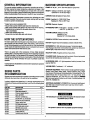
Effective February 1,1989
HydraMaster warranty covers oniy defective materiais andlor workmanship for the periods listed. Labor, and/or diagnostic reimbursement is
specifically excluded.
HOURS
Monday -- Friday
8:00 am To 5:00 pm
PACIFICSTANDARDTIME
3
TELEPHONE
NUMBERS
(206) 775-7272
(206) 775-7276
(206) 775-7275
(206) 771-7156
Generai offices
Parts Department
Service/Warranty
FAX
ILACEMENT OF UNIT
4 VEHICLE
TRUCK SELECTION
The preferable vtllclefor HydraCat iristallationis apam?l van with a heavyduty swyx?nsirm package. The capacity of Iho van should be a heavy-duty
1/2 ton at ttm minimum and more preferably a 3/4 ton o&pacity.
we are two recommended unit placements:
SIDE DOOR: Most installations are side door. This provides rearamss
paccessories and hoses as well as unobstructed access to compmwnti
]rfdng side of machirw, thus making it a bit easiw’ io perform maintenance
IWorrepair without removing unit from the truck.
TRUCK PREPARATION
The manufacmrarmmmmands theinslallation ofpl~od flooring covered
wiftr paly propylene backed astroturf (do not use rubber-backed) in the
vehicl~ prior to installation of machine. This provides a metal to cushion
mounting rather than metal to metal, provides insulation and makes an
attractive van interior. Aslroturf should be color keyed to van interior.
REAR DOOf%Afthaugh this location partly limits working access, itdoes
wet the noise away from the cleaning site. Some cleaners in the colder
eas prefer this location because if puts the weight mass ow?r the rear
~eels for better traction in ice and snow. Rear mounting requires ttw unit
be slid to the right side as far as possible. This not only provides adequate
xking space on the component side of the unit but also makes better
sight distribution inside the van (engine and cornponer?tweight line up
~erdrive shaft). Also, it is physically easier to load unit into rear door due
height of van bed.
Materials Needed:
1.2 sheets 4x8x5/fY exterior plywood
2. &xl 2’ piwe of commercial astrotwf
3. 16-f lM sheet metal screws
4.1 quart marine adhesive (optional)
5.1 staple hammar wII12” staples
(See illustration for correct placement of plywood flooring)
rrsure that machine is well secured to the floor of van with hwchvafe
~pplied.Sudden orwash stop Wlcause machine to rocket foru%wd,all 750
s. wrth! Protect yourself and the machimz SECURE lT#
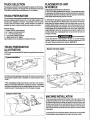
TRUCK PREPARATION
ILLUSTRATION
Machine Tie f?own Cleats
I
FIRST, covtwth~ truck kd with 5/8’ p@vood using metal screws to secure
it as shown.
Plywood Immlwcm
5/8” Plywood
SECOND, wlecttWappro@ate coloras!roturfto match yourvan andcm
tie plywood and staple in place. A standard van requires a piece 6 feet b]
12 feet.
Hydrafdasler strongly recommends an aluminum roof vent be in
stalIed over Ihe location selected for mounting the machine. HydraMaste
alsohighly recommends a flue be installed between the lop of the heate
and the roof vent. Thiswillallow hot air from the heater to escape.
THIRD,
UIACHINE INSTALLATION
‘here are two ways of positioning the machine in the truck as shown. Thwu
re also two locations for the vacuum recovw’y tank to be pasitiom?d. l%%
w?standard way with fhe tank directly alongside the machine. %?cond,with
Ie tank across the back of the machine as shown on the illustration on the
Iext page; this location is most spaca eflicient. Whichew?r way YOUsdect,
lake sure the tank and machirm are secured to the tloorof the van to insure
Iriver safety.
t is important that the machine lx? placed as close to the door as possibh?
o that outside air can b pulled into the engine for proper cooling.
4
I
I
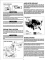
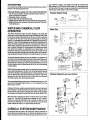
HARD WATER AREA MAP
::
——
—
E
Machine Configuration
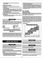
quality of water variis greatly throughout the United States and
influences the reiiibility and effiiienoy of equipment in direct proportion to
its !evel of hardness. The map below detinesareas which cornprumise fluid
related components such as hoses, fittings, heaters, pumps, valves and
water cooled engines.
The
0 :.UrloidB----
Cleaning efficiency and equipment life is increased, chemical use decreased and the appearance of cleaned carpets enhanced when water
softeners are incorporated in hard water areas. Manufacturer strongly
urges the use of water softener units in areas exceeding 3 1/2 grains per
oallon. Using the legend as a reference, determine the quality of water in
~our area aid take ;ction immediately should it be nece&a~.
Ii isrecommendedbyfhe manufacturerthatthe exhaustfi’om the frontofth
machine be venfeddown under the truck to prevent carbon monoxide frof
entering ihspb We. Aiwayspark the fruckso the exhaustis bfowiq
away torn Ihejob site.
IWater Hardness
Themanufactureraiso recommends that instillation of aluminum vents i
the truck roof to a//ow heat from the heater to escape.
$
t
Never operate this machine with a portable propane tank oraportable ga
can inside the truck, doing so increases the risk of a fire or explosion.
Mount afire extinguisherjusf inside the rear or side door foremergencie:
PROPANE TANK LOCATION
..
Grains
Per Galbn
Either the 10 gallon or 16.5 gallon propane tank will fit this location. Hav
you local propane dealer install the tank you select and purchase. Th
machine will come with the proper propane regulator. fTank must hav
vaporoutiet.)
Professions/insta//ation offudsystems is strongly recommended. Aiwq
ensure compliance with stite andlocdregulations pertaining to fueiinsta
Iations.
n
‘-3iQ
Izzzz
31/2-7
=
7-101/2
_
101/2 and above
WATER SOFTENER
Many areas of the country have an excess of minerals in the water which
results in what is commonly called “hard water”. These minerals tend to
adhere to the insides of heater coils andotherpartsof the machines causing
damage and a loss of cleaning effectiveness.
Reports from several of our machine users commending the results of the
use of water softeners inconjunctionwith their machines prompts us to recommend the procedure to everyone in a “hard water” area.
The relatively low cost of a water softener service is more than made up for
in the increased Iifeof machine parts andcontinuedcleaning efficiency. The
water softener will also increase fhe effectiveness of the cleaning chemical
being used, therefore, less chemical will be needed.
Contactawatersoftener distributor in your area forinformationon the rental
of a simple water treatment unit to carry in your truck. Be sure to change the
water softener in accordance with the capability of the softener. Example:
Ifthe softener will treat 900 gallons of water and machines uses an average
of 30 gallons perhourof use, andanaverageof 5 hours a day, wouidbe 150
gallons a day. 5 days would equal 750 gallons of water, therefore, the
softener would be changed every 6 working days for maximum softening.
(s6eil@laum
,wpi?#e)
5
Garden I-fose
START UP
—
1. Perform daily/periodic mainttrnance as specifbd by the owrws manual.
2. Connect all required hws.
, 3. Connect c!eaning tool to length of hose required to perform clwaning.
C#
h-morning VVatar
From Faucet
L Mix tankmust&M/priorto @rithmr.
Water Softener
WASTEWATER DISPOSAL
ADVISORY
Them are laws inmost communities prohibiting the dumping of recovers
‘gray” water from carpet cleaning in any place but a sanitary treatmel
system.
This cleaning rinse water, reccwred into your unit%vacuum tank, contair
materials such as dete~ents, which must be procwed before being se
for streams, rivers and reservoirs.
IN ACCCMM2AMCE WITtf THE EPA, STATE AND LOCAL MWS, D
MM MWW$f OF WASTEWATER MK7 GUTTERS, ST0f?h4 DRAIN
STllEAA@ RESEJ?Vt’WS, ETC.
Inmost cases, anacoep!ab[e method of wastewaterdisposal is to discharf
into a municipal sewage treatment syst@m after first filtering out sol
material suctwmrrpetfiber. Access to the sanifwy system can be obtaim
through a toilet, laundry drain, carwash drain, RV dump, etc. Permissi[
should first be obtained from any concerned party or agency.
One dis~sal rmtfwd which usually complies with the law is to accumula
the wastewater and haul it to an appropriate dump site. Another solution
the disposal pmblam is !0 equip yourself with an Automatic Pump-O
System. Thetm systems afie designed 10 remove wastewater from tl
tixtractor’s rwoovery system and actively pump the water through hoses
a suitable disposal drain. Properfydesignecf, they will continuously monii
tie Iml of wasttwvaler and pump it out simultaneously to the cleanil
operalion. Tim hidden benefit of this procm is thatthe operator does
have to stop his cleaning to empty the recovery tank. HydraMaster mak
an A.P.O. System available which can be ordered with new equipment
installed Iat@r.
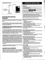
. Start engine (choke as required}. Engine is at operating speed (r@cam
mended -2600 RPM). Allow warm-uP period of 2-5 minutes.
I 6. Spray wand to void al air from system: When the mix tank tmgins a fill
cycle, the chemical flow meter may be adjusted to your desired setting.
NOTE: Recommended carpet cleaning pressure is 300 PSI.
7. Once all air is voided frum system, heatw may be ignited.
NOTE: If not familiar with operation of this healer, refer to heater section of
the manual.
A. Open propane valve on the tank.
B. Ignite pilot on the heater.
C. To ignite burner, turn dial to “on” position.
NOTE: If you suspect that the unit has been frozen -DO NOT light the
heater. Thaw the heater and check for leaks.
8. Turn on burner, adjust dial to normal or slightly below for 200W.
9. Commence cleaning operation.
NOTE: Chemical flow meter set at 5 GPH is a 1 to 30 mix ratio and 10 GPH
is 1 to 15 ratio.
NOTE: Hot cfbnate opw’ation [above 90°F].
When operating this unit in a hot climate, HydraMaster highly recommends
some additional precautions.
1. Operate with side and rear doors fully open.
2. Vent heater through the top of van.
3. If vapor lock conditions arise, machine cover may need to be raised to
allow additional heat to escape from canpwtmt?nt.
NOTE: Cold cfimate operation (below O°F).
When operating this unit in a cold weather application, HydraMaster highly
recommends some additional precautions.
1. If nossible carrv Your own fresh water SUDDI%
2. Hookup to ho~wkder source if possible to’keep your incoming garden
hose ~m freezing.
3. Do not close van doors in front of machine.
4. Be aware that solution lines laying on frozm ground may frewe.
5. Contact local propane dealer about cold weather propane use.
Thi?penalties for nwr+ompliance can be serious. Always check local la’
and n?gufaticms M be sum you are in compliance.
SHUT DOWN
1.Turn heater to ‘off”
position. Spray wand for at least 3 minutes to allow
the heater coils to cool.
2. Close valve on propane tank and through floor hookup.
3. Remove vacuum hose.
4. Flush clear water through chemical system for 10 seconds. (Vinegar
should be rinsed through system weekly.] Turnoff chemical flow meter.
5. Tumon cleaning tool to flush chemical from unit hoses and cleaning tool.
NOTE If freeze guard is necessary, perform steps 1 & 2 of freeze guard
procedure at tlls time.
6. At this time, the blower should be lubricated with Pennz@xwd.
7. Shut engine down.
8. Drain vacuum tank. Vacuum filter should @cleaned prior 10mobilization
of van. NOTE If freeze guard is necessary, pwtorm st~ps 3-7 of fr@ez@
guard procedure at this time.
I
MACHINE AthKISTMENTS
Although MS unit has been factory adjusted, it may require additiol
adjustmentsto achieve optimum performance; i.e. altitude may require u
adjustment and ambient temperatures may require heat control adju
ment. When required, cansult an authorized ~epresentative.
6
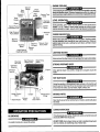
ENGINE COOLING
Vacuum
Hour Gauge
I
Meter,
Units employingaircooledengines mustnotln? enclosed withina van with
doors and ~ndows closed. Excessive temperatures within the engine will
resultinpremature engine failure anda compromise ofappiicable warranty.
I1’,J:ue
/va:%Tank
Pressure
Gauge, \
Temp.
\\l
Gauge
/
Circuit
Breakers
l/~
,,
Choke
LEVEL OPERATION
“
During operation, van or tiailer must be parked on /eve/ ground not to
excwed + or -1P. Failure to insure proper leveling may prevent proper
internal lubrication of engine, vacuum anoYorhigh pressure components.
Vacuum Pump I ;J
Lubrication Port &;
~’
)
High Pressure ~]
Pump Switch ‘~l
#I
!!$;
‘/
#
Machine _
Exhaust
FREEZE PROTECTION
‘Machine
‘vacuum
‘ank
Dump Valve
/
Incoming
Water
/1
Hiah Pressure’
Cle%ing Solution
Exhaust
Mother nature oives little wamin~ as to her cold s@ls. Therefore, wtectirrg this equifient from fi’eezing will save cosfly down-time. Placing an
electric heater in the Puck or parking the truck indoors, will help to insure
against fleezing.
Bv~ass
Valve
LIGHTING HEATER
Neverputyourface
Chemical
.. —
High Pressure
Water PumD
down close to the opening of the heater when lighting.
Water Pump
Clutch
STRONG PROPANE ODOR
Engin6
Never light the heater if you smell a strong odor of propane around the
heater.
/’
HOT SURFACES
During the operation of this equipment many surfaces on the machine wili
become vetyhot. When near the van foranyreason care mustbe taken not
to touch any hot sudace, such as heater, engine, exhaust, etc.
Heater Control
Valve
Hydra-Heater
Coupler
Vacuum
Pump
\
Mix Tank
Drain Valve
‘Freeze Guard
Fitting
MOVING PARTS
Never touch any pad of tie machine that is in motion, severe bodily injury
may result.
CARBON MONOXIDE
NO SMOKING
This unit generates toxic fumes. Position the vehic/e so that the fumes will
be directed AWAYfrom the job site.
ftis unsafe to smoke in or around the vehicle.
DO NOT PARK where exhaust fumes can enter a bui/dif?g through open
doors or windows, air conditioning units or kitchen fans.
7
FREEZE
PROTECTION
CLEANING AND CHEMICAL
PRECAUTIONS
Any frw~zing of this machine is not covefied by warranty and during the
~ldelrmantisofo~mtion,
careful protection should be of utmost concern.
Yourmobile carpet cleaning plant has been engineered using the !at@stand
nest sophisticated technology available, to produce the finest carp@t
~eaning results possible. Despite this, however, it remains onlya tool of the
xpet cleaning trade, and it can produce only as good a job as Me person
]Perating it.
THE FQLLWW4G PRECAUTIONS ARE RECOMMENDED:
1. Run machine befcm leaving for the first job to insure nothing has frozen
ha night lmfore, including hoses and wand.
2. Insulak the gafidt?nhose from the cold ground by running it through an
extra 1 1/2 inch vacuum hose.
3. In colder dirnates, insulating the truck walls and floorboards will help
prutoct the unit.
4, Don’t procrastinate during thec!eaning operation or the hot water solution
line will alw freeze an the ground. The solution iine should be insulated
in exlrerrmly cold climates.
!$.Whenever ~ssible, the truck and machine should be stored in a heated
garage at night or over the weekend. If not possible, place a 1500 watt
electric heater inside the truck, aimed directly at the machine. Never use
a propane heater-it causes excessive moisture on the truck ceiling and
the possibility of it going out is higher. If the machine and truck are left
outside with a heater, you should first drain of possible water from the
There are not short cuts to good ca~t cleaning. It requirws time, cleaning
mowledge and the use of good chemicals.
The manufacturer recommends the use of spotting agents, and traffic lane
nleaners prior to the actual cleaning of carpeting, as required.
The use of some chemicals through your mobile carpet cleaning plant can
seriously damage the internal plumbing, high pressure pump and heater.
(Chemical such as concentrated acids, solvents, and some paint oil and
grease removers w/high cwwentration of solvents.)
The manufacturer recommends only the use of chemicals containing rust
and corrosion inhibitors and water softening agents to prevent chemical
build-up which may lead to component failure and warranty invalidation.
machine cleaning tools and hoses. (They freeze also.)
TO DRAIN THE MACHINE FOLLOW THESE STEPS
1. Siphon a 50150 mixture of anti-freeze and water through the chemical
ftow meter.
2. Drain the mix tank.
3. Connect Ma freeze guardhow? to the rwxwery tank.
4. Connect Ihecdher ond of the freeze guard fitting to the freeze guard fitting
Iocatfid on the sido of the machine.
5. Connect an open 440 quick connect to the fittings marked “cleaning
solution” on the front oithe machine. (An alternative would be to connect
your solution hww and wand, w as to freeze guard them also. If you
choose to do thisycw will also need to hold the !riggerdown on the wand.)
6. Start the unit, allowing the vacuum from the machine to drain the lines.
7.* Remove tfre garden hose inlet adapter from the end of the garden hose.
Conrmct the adapter to the incoming water quick connect on the front of
9hemachine.
8.’ Place a vacuum hose over the garden hose quick connect and allow the
vacuum from the machine to drain the lines.
* i4n alternative to #7 & 8 would be lo make an adapter to allow you to us@
the premade freeze guard hose.
NOTE: At no time should a chemical solution with a pH of less than 7 or
higher than 10 be used in the unit.
I
1234567891O
I
1
)
+AOD
I
I
-
I
I
I
I
I
1?12
I
I
13
I
14
I
NEUTRAL
*
‘ALKALINE~
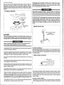
CLEANING STROKE
PROCEDUREIOVER-WEUING
PIJRPOSE:TO eliminate excess moisture rernainirrg in the carpet fiber and
the sawtooth appearanw? which results from diagonal movement of the
cleaning tool on all types of carpet.
NQTE: Prior to freezo guarding your rnachinemake sure the heating system
has been cooled down.
ALTERNATE PROTECTION
ANTI-FREEZE:
pH CHART
PROCEDURE: Always move the cleaning tool in smooth foward anciMckward strokes. Apply slight pressureto the forward stroke while the solution
is injected into the carpet. When extracting (drying), apply firm pressure on
the foiward stroke to ensure a positive “lock” for the vacuum and minimize
the “hopping” effect resulting on unsmooth carpet. During the forward and
reverse strokes, movement to the right or left should only be a~omplishexi
at the extreme rear of the stroke. Overlapping is also important to ensure
even application of solution to prevent saturation when cleaning wand is
stopped twice at the same point at tie rear of the cleaning stroke.
USING
1. Follow We draining procedure.
2. Cmnect solution hoses and wand to machine.
3. Pour a 50/50 ariti-$reeze sokJtion into mix tank.
4. Turn on machine and engage clutch. Spray the wand.
5. Continue to add anti-freeze solution until mixture comes out of wand set.
6. Remove and store hoses.
Failure to adoot this mocedure can result in increased chance of “clean
streaks”, fiber’shrinkage, brown out, and longer drying pdods.
INCORRECT
If you are using an anti-freeze solution to protect your machine from
freezing. 1[is ne~ssary to flush the machine in preparation for use. Simply
connect the unit to fresh water and spray the wand until anti-freeze solution
is discharged. The anti-freeze soiution maybe recovered by spraying into
an empty container. This solution can be used several times.
METHOD
CORRECT
Overla~
MEWMN2
Between
Strokes
pfl~q-!,ir!
‘<!,.
BE SURE IT’S PROTECTED! Freezing will cause GRIEF, MONEY and
DOWF&TIME. Don’t mess with Mother Nature!
Cbanmg
Stroke
8
Cleaning
Stroke
OVm”wmmlci
uart container of vinegar. This should be done with the Chemical Flow
!eter setting on 10 GPH and the Water Heater “off’. Simply spray water
om the wa~d until the quart of vinegar is exhausted, the repeat the @wess
ith one quart of clear water to void all lines of vinegar.
Over-wetting is annoying to all concerned and sometimes leaves a bad impression of the cleaning process used.
THESE ARE SEVERAL AREAS THAT WILL CAUSE OVER”WEITING:
1. Too Iew vacuum strokes or improper sawtooth vacuum strokes as
shown in the previous illustration.
2. Obstructed, kinked or cut hoses.
3. Vacuum tank drain valve left partially open.
4. Clogged vacuum blower filter or vacuum tank lid not sealing propxly.
5. Cleaning a heavily foam-saturated carpet without defoamer. (We recommend crystal type.)
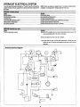
Chemical System Wiring
Solenoid Valve
,.~
Relay
E
,.~
X!/’
To Ignition Switch
Float
Switch
88
~.
h.
‘--l
G~D
WATER AND CHEMICAL FLOW
OPERATION
GND
85
‘..
Water Flow
This electro-mechanical system has been designed to be simple and
trouble free. Incoming water flows first through the Solenoid Control Valve
(1) and the low pressure Chemical Injector (2) which are both mounted on
the exterior of the mix tank. As the water passes through the Chemical
Injector, it is automatically proportioned with a predetermined quantity of
detergent. The MixTank(3)isequippedwith two different float switches, the
Water Level Float (4) responds to the level in the tank and will maintain the
proper volume of solution to be reserved for the water pump. The secondary, Low Water Float switch(5) isasafetyswitch that isdesignedto protect
your system from sudden or unexpected loss of water supply. If, for
example, the water source at the house were turned off, the water level of
the mix tank would drop, activating the secondary switch, which automaticallydisengages the system and pn?vents the water pump from running dry.
The desired chemical injection ratio may be obtained by an adjustment of
the Chemical Flow Meter (6) during the fill cycle of the mix tank. Water must
be flowing into the mixtankinorderto adjustthechemical mix. The chemical
will flow from the Chemical Jug (7) to the Chemical Flow Meter, then to the
Chemical Injector where it is proportioned into the Mix Tank at the desired
chemical setting.
678+
NOTE: %Mththisuniquechemical system, thechemicalflow is proportioned
only during the filling cycles of the MIXTank, not during the direct spraying
of the wand. Therefore, it is possible that as your wand is spraying, you may
have no chemical flow. Also, the converse is true in that you may not be
spraying your wand, but if the mix tank is in a filling cycle, your Chemical
Flow Meter may be active at the desired flow rate.
Chemical Flow Meter
Chemical Jug
High Pressure Pump
High Pressure
11 121314+
Pressure Guage
Incoming Water
Tank Drain
To Wand
Low Pressure
Chemical Proportion and Level Contra\
M,, Tank
6FA-6UFS
I
$
The chemical proportioning system will mix chemical with water at a 1to 30
ratio when the Flow Meter is set at 5 GPH, or a 1 to 15 ratio when the Flow
Meter is set at 10 GPH.
~u
At this point in the flow, solution (water with chemical) will now be siphoned
from the bottom of the Mix Tank to the inlet of the Water Pump (8). When
the wand is not using solution by spraying, the solution will be bypassed
from the bottom of the brass Pressure Relief Valve(9), back to the Mix Tank.
-0
=eCk=
Swng
B
o SIs Ball
&
.
Check valve
fl
‘“’W’”’
B””’
;
*:5$3’’HeFj
~jii$
When the wand is spraying, the solution continues its flow to the Water
Heater (10). The coils of this heater have a capacity of up to 2 gallons,
therefore it is extremely important that all air pockets are bled out of the
heater prior to initial start-up. This maybe achieved by running the water
system, without the heater on, for approximately 80 seconds.
g;zj_:Dlen;n
q~
Mo.n!tng
+wJw
CHEMICAL SYSTEM MAINTENANCE
,3)
(la ‘
—.
The chemical lines may need to be flushed with vinegar periodically to
prevent abnormal chemical build-up. This flushing may be done by removing the clear plastic hose from the Chemical Jug and inserting it into a one
+-=”
,-,4,
—-,
-
–d
12 Voc
cm
9
.—
Mo.ntlng
Plato
va,vech,y
Water
Idet
I
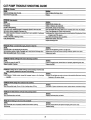
CHEMICAL TANK
TROUBLE SHOOTING GUIDE
PRQHLEW. Uttla
%hldon
Wand Valve Asswnbfy
I
I
or no chemical flow
I
Chackthtat hoses af the Mix Tank(3) are secure. Check that the hose from the top
of tkw Flow MrXar (6) to the Chemical lnject~ (2) is seam with no kinks or
leaks, (M& thal the ad~ustingcap on tho side of the injector is INI! screwed
af!ttw way in. Clmcklhe $/s check vafveirw.idethe injedorforchemical build-
I
~
II I *C
-T
Ekldy
up and pqer qwration. Chec& the hose from the botiom of the Ffow Meter
to the Ctmrnicaf Jug (7) for kinks, cracks, or bubbles.
Cf’mckthwxraen ontheemdof the hose which gces intotheChemicaf Jug. Tochack
thii scram for proper function, remove it kom Itw plastic hose. If you csnnot
blow Ihrough if, tti rinse if out with vinegar.
Check the Chemical flow Meter (6) for obstructions or a sticking float.
Is incoming waler pressura less than 30 PSI?
Cracked w cle!ective Chemical Flow Meter (6)?
Check the fitter wren in the Solenoid Control Valve(1).
Compression
Fitting
QI
I
--~;~’
~?
*
*
O-Ring
i
3’L%
frmbillty to adjust chemical with the Flow Meter
O-Ring
Plunger
Quick
Connect
cap
PROBLEM
=*I6
:11
\“?’<F~@
.\
Spring
I
[\
Cl-Ring
Keeper Ring
Sahtion
Debrii Iodued &hind Mlon %at in Flow Meter valve.
Tdhm seat on the valve stem maybe hose. If deteriorated, replace O-Ring.
PHCWLEM: Solution rmmrsbrg from Mix Tank, ffllhrg the Chemical Jug
Sohlfk?n
Anti-siphon dwice cfogged by chemical build-up (Anti-siphon device is bcated in
the Chemical Injedor (2) body — see page 9, Water F!aw illustrakon).
Check for debrii.
PRQBLEM
Jet Assembly
Ekdy
FAx Tank overflows
mlution
Float awitc+r(4) in the Mix Tank nd moving ireely, or d~fadive.
TochmckswitctrWNma 12voht@[ghiandtheilut
inthe”up”position, there should
b power through the swhh.
To check relay: First check wiring against dmgram. W*
12 volt lest fight, and the
FloafSw%ch(4} inIfre”up”posilierr there sf?cmklNOT@owerat
!heSolenoid
Vahw. Wth !he Float Switch in the “down”position there should be power af
the SIoarwid Vafve.
EKderroidValve defectiwx Remove Solenoid Vafve, disassemble and inspect
Wand Assembly
diaphragm Iw cracks w tears.
PRQ5LE~
SOlufhltl
Mix Tank does not keep up with water output
Ha
Check incoming water pressure. Check gaden hoaa quick conned
assembfy screen.
Check garden hose ardor feed hose 10 the Mix Tank for dog, kinks,
‘b”
or blockage.
Float Swifd (4) in Mix Tank hanging up (rmf moving freely). Check fifter scmn in
Solenoid Vafve (1).
10
I Wand Valve Stem Assembly
I
@
Keeper
Bypass Valve Assembly
+—
Retainer
Ring ———+
~
(
O-Ring
Plunger —
u
BYPASS PARTS LIST
REF. NO.
3
I
@—
O-Ring
I
PART NO.
DESCRIPTfON
4
5
OOO-105-1OI Thrust plate, Bypassvatve
OOO-105-1O2 Piilon plate, Bypassvalve
OOO-O78-1O1 Kt, seal for Bypass vafve
7
8
000-14B-oo4
000-097-005
Seat & C43ing, Bypass vafve
O-Ring, Bypass valve fitting
QTY.
1
1
1
1
1
WATER FLOW TROUBLE SHOOTING GUIDE
PRoBLEkk LOSS of pressure
Cslrse
=ve
or blocked check vafves in high pressure pump cyfinder head.
solution
Delaminated, Idnked or dogged hose between the mix lank and fhe high
Disassemble cylinder head and replace or cfean applicabfa check valve.
Remove and replace defective hose.
pressure pump,
Defective pressure refief valve or debris in pressure relief valve. NOTE lle high
Disassemble and clean pressure relief valve as illustrated in drawing above.
pressure bypass vafve is desgned to fully dose when the cleaning teal is
turned on. Any foregn matter colleding on the piston will prevent iull closure
of fhe valve id allow a portion of the water to continue to circulate instead of
being routed to the ciaaning tool. To correct this situation, the bypass vafve
must be disassembled and dearrad (refer to illustration provided abve for
bypass disassembly).
Oelective or worn cups.
Loose driie belt Ior high pressure pump.
Pump inlet Ystrainer dogged
Replace defective or worn out bypass cup.
Replace bypass valve.
Remove and replace piston cups as defined by pump manuat.
Readjust belt as required or replaos if defective.
Check lank for water. Clean strainer. Clutch disengaged?
PROBLEM: Excessive water flow
cause
Solution
Worn out spray jet. NOTE: Cleaning tools designed to spray a constant fbw of
1112GPM will average 1 gafbn of flow per minute in adual working situations
since lbwis not continuous.An average flow of 1 GPM results in 6000gallons
of fbwforevery 100hoursof unito~ration. Spray tips arecapableof fbwrates
for approximately 20,000 gallons. They should beraplacedtherefore, approximately every 350 hours, Worn spray jets allow a greater average rate of flow
thus reducing desired temperature fevels.
Reduction of flow.
Remove and replace spray jet.
Due to increased length of sloution hose. NOTE For every 50feat of hose, bevond
,
100faet intotdlength,ame~urtile
losoffbwisexpenencd.
Ttiscondition
is a result of the increased fridion experienced by the water as it passes
through the hose. Therelore, if is necessary to increase the pressure at the
machine 40 PSI for every additional 50 feet of cleaning solution hose over
100 feat.
11
—
VACUUM SYSTEM INFORMATION
MXIUM
The vacuum blcwwr incmporated in this machine is a positive displacement
Iokwtype, manufactured by Cooper Industries. The performance and fife oi
this unit is gfieatiy dependent on the care and proper maintenance it re
Ceiv@$.
/drafdasler filter bags are designed to trap all of the lint, sand and dirltha!
wld normally collect at the bottom of your vacuum tank. The w? of these
lgs, if emptiid at the end of each job; will eliminate the build-up cd much
thedebt%in the tank. Th@drawstring top of these bags is ckmigrwd to be
d to the incoming dirty water inlet in the vacuum tank.
Becauw?of the CIOWtcdmum.es between the lobes and housing of the vac
uum blower, did objects entwing the inlet will damage the internal lobes,
g~ars and bearing or direct drhm coupler.
TANK FILTER BAGS
Jreorder bags use part number 049-029.
Vacuum Tank Filf@r Bags
To p~event this, a stainless steel filter screen has been placed at the vac
uurn inlet inside the vacuum recovery tank. This stainless steel screen is
finger tight and should be removed for cleaning weekly.
.Vacuum
Tank MM
When machine is Ming run fir iesi purposes and the vacuum inlef on fo~
of machine is open, caution should h? used.
To protect Ih@vacuum blower from overloading and damaging itself, thert
is a vacuum rdi~f sys!em installed on the vac tank. When the vacuum tan}
inlet is completely sealed off, a maximum of 14 HG will be attained. A hok
on the top blower pipe eltmw acts as the lubrication point. At the end of eact
day, LPS 1 or Pennzguard should be sprayed in before shutting down th[
machine. See blower lubrication W4ration. If you fail 10 Iubricaie tfw
vacuum blower daily, rust doposils and moisture will decrea~ the life of ttw
vacuum Mower.
\:7
Read the vacuum blower rnanualcarefully forpmperoil change and greaw
application. The maintmarm log may differ slightly from the manual, bu
the truck-mounted carpet cleaning machine application is very demandiry
of the vacuum blowerandtherefore it should be maintained more regularly
Blower
LubePort
NOTE: Vacuum tank isprotecfedfrom ow?rflowirrg bya vacuum tank, flea
kill swi[ch. This swiich is not acfiwated by foam, only byliquid.
I
vacuum Flow
S/S
Filter
\
Recovery
Tank
Filter Bag
/
\/
L
Spray lubricant into bloww’ lube port for 3 to 5 seconds,
then immediately shut off machine. Use only LPS 1 or
Pennzguard moisture displacing lubricants.
12
VACUUM BLOWER WARRANTY
FULLER warrants products of its manufacture to be free from defects in malerial and workmanship if properly installed, maintained, arid operated
under normal conditions with competent supervision.
No person, agent, representative or dealer is authorized to give any warranties on behalf of FULLER nor to assume for FULLER any other liability
in connection with any of FULLER’S products.
This warranty shall extend for two (2) years from date of installation provided this equipment has been put into servicw within six months after
shipment from tie FULLER factory. If repairs or replacements are made by the Purchaser without FULLER’S prior Mitten consent, FULLER’S
warranfyshall cease to be in effect. No allowance will be granted for any repairs or alterations made by the Purchaser without FULLER’s prior written
consent.
Machinery, equipment and accessories furnished by FULLER, but manufactured by others, are warranted only to the extent of the original
manufacturer’s warranty to FULLER.
FULLER agrees at its option to repair at the point of shipment or to replace without charge f.o.b. point of shipment, any part or parts of products
of FULLER’S manufacture, which within the specified warranty period shall be proved to FULLER’S satisfaction to have been defective when
shipped, provided the Purchaser promptly notifies FULLER, in writing, of such alleged defect.
FULLER’S liability to Purchaser, whether in contract or in tort arising out of warranties, representations, instructions, or defects from any cause
shall be limited to repairing or replacing of the defective part or parts as aforesaid, f.o.b. point of shipment.
No liability whatsoever shall attach to FULLER until said products have been paid for. EXCEPT AS STATED IN THIS SECTION AND IN THE
PRECEDING SECTION TITLED ‘WARRANTY’ AND EXCEPT AS TO TITLE, THERE ARE NO GUARANTEED OR WARRANTIES OF
MERCHANTABILITY, FITNESS, PERFORMANCE OR OTHERWISE, EXPRESS, IMPLIED OR STATUTORY, AND FULLER SHALL HAVE NO
LIABILITY FOR CONSEQUENTIAL, INCIDENTAL OR OTHER DAMAGES, HOWSOEVER CAUSED.
DATE INSTALLED
MODEL
SERIAL #
FULLER COMPANY 2966 East victoria Street Compton, California 90224
.
VACUUM BLOWER LUBRICATION
Vacuum Blower Motor Lubrication
At the gear end the timing gear teeth are lubricated by being partially
submerged. The gear teeth serve as oil slingers for gear end bearings. At
the drive end of the bearings are grease lubricated.
FILLING PROCEDURE
Remove square head vented oil fill plug (A) on gear end. Remove oil level
plug (B) located in the head plate. Fill gear case until oil drips out of the oil
level hole (B). Use lubricants as listed. Add fresh oil as required to maintain
proper level. The oil should be drained, flushed and replaced every 1500
hours or more frequently if inspection so indicates. The oil drain plug is
at(C).
NOTE: Older units may have the oil fill level and drain holes located in the
cast iron gear case instead of in the head plate. Bearings on drive end of
blower require grease lubrication every 100 hours of operation. Bearings
which require grease lubrication will have a grease fitting (D) at each
bearing. When regressing, the old grease will be forced out of the vents
during operation. To prevent damage to seals, these vents must be kept
open at all times.
1
13
VACIKJM BLOWER TROUBLE SHOOTING GUIDE
PIW5LEM
Loss cd prw$si.irn
Carkm
Solution
Remove and replam hose. NOTil A .speckd r@irrfcmd hose is requirwd
for replacement.
Remove and dean or replaca stainless steel filter.
Remove and raplw vacuum lank seal.
Close valve.
Replace valve.
Collapsed vacuum hose between blowm and vacuum kink.
Chfjgad skddese steel Ikmr,
IMwAive vacuum lank seat.
Dekctive or %p@ vacuum tank pump valve.
Fraclured weld on vacuum tank.
Re-weld as required or replace tank.
Reshape h= if po~ibla andlor eliminate kinks.
Remove obstructions by reversing the vacuum hose.
Remove obstruction.
Replace worn components. NOTE Must be accomplished bya qualified technical,
Inspect and replace if necessary.
Gallapsed w kinked vacuum hmw.
P%Jggedvacwn hose.
Restriction in cleaning tool.
Worn @ndplates or lobes in vacuum blower.
IM3ctive relief valve.
WNIBLEW
Cause
B!mver k+ seized
Solution
Rust.
Spray rusI dissolving lubricant onto lobes to emulsify rust and attwnpt to ro$at~
vacuum lobes.
Foreign matter.
Disassambieand remove foreign matter and reptiras r~quired. NOTE: Disassembly must be accomplished by qualified tedrrrican.
tite:
fie ahvernwrtiorred, Nst foreign rmaftt?rarrdseizingare
foam traveling through the Mewer.
lWOtN.EW
Nab
in
often causal from
vacuum blower
calm
Soiutfon
Worn gears.
Remove and rap[~ gears. NOTE: Replacement of gears must be accoinplishwl
by qualifii tedrnicarr.
Lack of lubrication. NOTE Permanent damage may have resulted from lack
of lubrication.
bwing$.
Timing ofvacuumblowerhasbeen changed duetow-orncomprmnts. Replacement
of components must be accomp!iihad by qualified technican.
Lubriite as specified by applicable vacuum blower manual. Sea index.
worm
Remove and replace bearings as required. Must be accmpliihad
technican.
Ikbris and/or foreign materii build-up. NOTE: A sfahdess steel filter isprovided in
vacuum inlel located in vanmm blower carnpcments.
Disassemble vacuum blower and remove foregn materii. NOTE: DkmssomMy
should be accampliihsd by qualified $echnkxrr only, Replacemwrt of worn
Lcme ar missirmgmmm[ing bats.
parts is nwssay.
Tighten or reinstall mounting bolts.
by qutified
I-IEAIING SYSTEM INFORMATION
heater incorporated in tfls equipment is a special design for
WM?in the carpet cleaning industry. It’s high pressure coils and thermostatic
temperature control make it simple to operate and reliable. Once thedwired
temp%ratum is set, the heater will then go ‘em’and ‘off’ according to the water
terrpwatum within the heater. As water is wed through the cleaning tool,
cold water entwing the heater will activate the thermostatically controlled
propane valve thereby firing the heater to maintain a consistent flow of hot
wattw. Once the cleaning wand is shut off and the flow of water through the
kmater stop% the treater will continue to burn until the set temperature is
attainfid.
It is pwsible with this design that the flame may be on when the wand is off,
likewise, it is passible the flame may be off when the wand is on.
The propane
This heaferis designedfo &urrJvaporproparreg’as oniy Anyiiquidpropar?e
entering the healer may cause damage to tfm contmi valve on the heater.
tt wili also cause improper burning and a soot buiki-up on the coil,%
Therefore, if is necessary to shutoff fhe h@a@rand close tho waiveat th@
tarrk between ciearring icmations. Failure to do ff?isaliows sloshing /iquid fo
enfer the vapor feed iine to the heater.
IMPORTANT: Overfilling of the propane tank will caus$ many problems. To
avoid this, advise the attendant filling the tank not tcttill the tank mrer$tl%.
When filling the tank, watch the 10% valve and immediately stop fillirtg when
14
white fiquid starts spurting from the 10% valve. To prevent damage to the
propane regulator, always cfose the valve on the tank before fflfing.
The propane regulator is pre-set at the factory at 6 oz. of propane. This
reading is taken at the control valve on the heater (see figure A No. 6). To
prevent road dust and moisture from entering the propane regulator, keep
the white plastic cover (supplied) on the regulator at all times.
To avoid restriction of air flow at base of heater, keep articles such as
chemical containers, hose, boxes, etc. from within 18 inches of base of
heater. NOTE This restricted situation also creates an over rich condition
which results in soot build-up.
lMPORTANf7 Ifa newpropanetank has been installed or hoses have been
disconnected, air may enter propane hoses and must be purged prior to
attempting to light the pilot burner. Should this condition exist, operator must
depress the pilot button for 1-5 minutes and attempt to ignite the pilot light
at 15 second intervals. A very slight hissing noise should be evident while
performing this operation.
Check heater forpropane leaks regularly as loading andunioadinghoses,
tools, etc., mayaccidentally bump against heater fitting or pipes.
fight the main burner, repeat instructions as above (TO START PILOT),
1 through 4.
OR,
Water may already beat controlled temperature.
Flame will turn off when thermostat senses maximum temperature.
To
C. TO ACHIEVE PROPER CARP~ CLEANING TEMPERATURE:
1. Complete procedures A & B.
2. with 100’ of hose, turn cleaning wand on for 5 minutes and the
temperature should stabilize.
3. Oncea constant temperature is established, turn cleaning wand ‘off’. The
flame on the heater burner should remain on for 10-15 seconds.
A. If the flame expires prior to 10 seconds, turn the thermostat dial to
a higher reading, then repeat C 1-3.
B. If the ffame remains lit after 15 seconds, turn the thermostat dial to
a lower reading, then repeat C 1-3.
D. TO SHUT DOWN HEATER:
1. Turn upper dial #1 to ‘off’ position.
2. Tumcieaning wandon for3 to5minutestocoo/heatercore. Ifi?eafercore
isnotcooled, itispossible tha(theheat retainedin the core wiilcause boiling
back into a chemical mix tank. This results in damages to Cat pump.
3. Close propane tank valve while
wand is on the heater is coofing.
HEATER OPERATING
INSTRUCTIONS
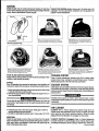
Heater must be fi)led with water prior to igniting.
A. TO START PILOll
1. Adjust thermostat control knob on unitrol to desired setting (#3).
2. Adjust upper dial to pilot position (#l).
3. Depress pilot button (#2).
4. Depress sparking button to fight pilot (#4).
PILOT BURNER ADJUSlllENT:
1. Remove pilot adjustment cap #5.
2. Adjust pilot key to provide properly
sized flame.
3. Replace pilot adjustment cap.
Allen head pipe pfug #6 can be
removed for monometer insertion
to read propane ounces.
HEATER TROUBLE SHOOTING
heat. Flames protruding outside the iower openings.
Csuee/So/ution
1. Maladjustment of propane regulator. tWTE Propane regulators are factory
PROBLEM: Excessive
preset and may be readjusted by authoriiad personnei.
A. Contact manufacturer to determine correct procedure.
IF PILOT FAILS TO LfGfiT:
Is propane tank full?
Is propane tank valve open?
Has air Men properly bled from propane line?
Is igniter system working?
WHEN PiLOTUGH7S:
Wait ten seconds, depressing button manually, then release button.
B. Have your local prcpane deafer use a marromeler at the Unitrol to reset the
propane ragufafor to 7 oz. maximum.
2. Overfilled propane tank. Propane heaters are designed to operate on vapor
propane only. Overfilling a propane tank affows ~quid propane to enter ail
heater reiatad components and permits an over-rich burning condition to
occur. This condiion usually requires the core to be deaned of soot and
carbon dapadts. Cleaning is a messy, dirty job and very inconvenient, so do
not iet if happen to you!
Always keep face away from main burner opening to avoid ignition
flash bum.
PROBLEM
B. TO UGHT MAIN BURNER:
1. Turn up~r knob to “on” position. Flame will come on.
If you do not get the burner to flame, the pilot has expired. You must turn
upWrdial to “or position. Do notattempt to re-light the pilot fort24 seconds.
Pilot
light
Cause/Solution
1. Pibt lightwill not ignite. NOTE: Do not use a naedleorpin to dean pilot orifii—
use compressed air or solvent only.
A. Verify propane reaching igniter. NOTE A tinkad or crushed hose may
impede propaneflow.
B. Remove and clean orifii.
C. Verify igniter spark is operating correctly.
15
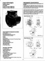
SPECIFICATIONS
CAT PUMP MODEL 290
OPERATING Ihlsmwmolw
CAT PUMPS am positive dispkwrmti
pumps. Therefore, a properfy
desigr?ed prt?ssurt?relief mffchanisrn IUUST be irstalled in Me discharge
piping. Fajlure to install suchmliefmechanism ~uidmsultin~rsonalinju~
or damage to ffwpwnparsystwn. Cat Pumps CorporabOndoesnot assume
afly liability ormsfxmsibility for the operatiorr of a customer’s high pressure
system.
Volume: 3.5 GPM (13 UM)
Discharge Pressure: 1200 PSI (83 BAR)
Maximum inlet Pressure: -8.5 to+ 40 PSI (-0.6 to + 2.8 BAR)
RPM: 1200
Bore: 0.78~ (20mm)
Stroke: 0.472’ (12rnrn)
Crankcase Capacity: 10 oz. (.3 L)
Maximum Fluid Temperature: 1800F(71°C)
Inlet Port (1): 1/2” NPT (1/2” NPT)
Chemical Injection Port (l): 1/4” NPT (1/4” NPT)
Discharge Ports (2): 3/8” h!PT (3/8” NPT) (l): 1/2’ NPT(1 /2’ NPT)
Pulley Mounting: Either side (Either side)
Shaft Diameter: 0.65(Y (16.5mm)
Weigh& 12.1 Ibs. (5.5 kg)
Dimensions: 10.77’’x9.08’’x14n4n(273.5x230x130 .5rnm)
Pracfuctsdescribed hereon ar~ covered by one or more of the following U.S.
patr?rls: 3558244,3652188,3809508, 3920356, and 3930756
.~..
,.
*CAT
PUMPS — AG 0
LorelohOelIe
5
CH.63CQ ZUG. Swtzerlana
Phone (42) 213140
– Telex 865 160 CPag ch
p#ziltH3ilm*y
P O 130K BS5 MINNEAPOLIS
MN 5S440
PbmIfI (6 12) 780.s440 — Telex 290278
OCAT PUMPS DEuTSCHLAND
Grnot+@
ROSlocker Sttesse g
62L12 Wlesbaden
BIef3tadl
West Germany
Phone 0612.5600
01(2 – Telex 41 86713
a N V CAT PUMPS INTERNATIONAL
S A *
Hmmonmstraat
29
8 2LlQtJAntwerp, 13elgwm
Phone (03) 2377224
- T@E,x 33947
-CAT
PuMPS [U K) LTD 0
27 Stallon Ina.strml
Estets, Flee!
H.9MD9hW3 Gu13 8QY.EnglamJ
Phone Fbl
22021 – Telex 8SSS93
C0F7P0RArt0N
CAT IPUMP WARRANTY
This Cat Pump (“product”) is warranted by the manufacturer to be free from defects in workmanship and material for orw year hum dat~ of
manufacturer’s shipment. This warranty is limited to repairing or replacing products which manufacturers investigation shows were defective
al the time of shipment by the manufacturer. All products subject to this warranty shall bt?returned F,O.B. Cat Pumps Corp., Minneapolis,
Minnesata 55430, U.S.A. for examination, repair or replacement
The express warranty set forth herein is in fieu of all other warranties, express or implied, incfuding without limitation any warranties of
merchantability or fitness for a particular purpose and all such warranties are hereby disclaimed and excluded by the manufacturer. Repair or
replacement of defective products as provided above is the sole and exclusive remedy provided hereunder and the manufacturer shall not be
arising from the sale or
Iiablo for any further 10ss,damages or expenses, including incidental or consequential damages, directiy or indirectly
use of this product.
This warranty is subject to the following warranty conditions:
impmlant Conditions- LUBRICATION - fill crankcase to the top of oil gauge window per specifications with Cat Pump oil or equivalent SAE
40 weight hydraulic ail with antiiear and rust inhibitor additives. Change initial fill after 50 hour run-in period. Change oil every three months
or at 500 hour intervals thereafter. FWrrrn-a-lube seals need no lubrication. Blue dot seals and wick must receive three drops of Cat Pump oil
per wick every 50 hours of operation.
GCXMI
LUBR1CATK3N IS THE EASIEST, MOST EFFICIENT AND LEAST EXPENSIVE OF PREVENTATIVE MAINTENANCE.
RPM and PRESSURE - Pump operation must be within RPM and pressure specifications. Pressure relief valve must tw installed.
00 NOT PUMP ACIDS OR ABRASh/E FLUIDS with this unit. Consult Cat Pumps for additional information on questionable fluids.
FREEZING CONDITIONS - Pump must be protected from freezing conditions.
USE CWOTHER THAN CAT PUMP PARTS OR THEIR EQUIVALENT VOIDS THE WARRANTY
16
—
PISTON MODEL 290 Exploded View
———
—.
.—— ———
PARTS LIST MODEL 290
fTEM
1
2
DESCRIPTION
O-Rino (Buns-N\
Crankcaee
Stud (M8 X 82)
O-Ring, oil filler cap
fTEM
35
QTY.
1
1
38
43339
43987
23170
25625
92520
438o4
14487
24159
2653$
Oil filler cap
O-Ring, crankcase cover
Crankcase cover
Bubble oil gauge
O-Ring, drain plug
Drain plug
Sems comb head screw (M6 x 20)
Crankshaft
Rearing
Oil seat (Buns-N)
O-Ring, oil seal case
2
1
1
1
1
1
t
1
6
1
2
2
2
20
27950
oil seal case
2
49
21
23
24
25
92519
101789
Iolmo
lMkUt
Sems comb head screw (M6 x 16)
8
3
50
26
20017
25301
25327
25392
28771
385880
4
5
8
9
10
11
12
15
16
17
18
19
,
PART NO.
202e5
44274
27
28
29
30
31
32
33
34
44377
44374
43340
29003
29614
26854
28597
25128
25635
Conneding rod
Pston rod
Pston pin
Seal washer
oil seal
Barrier slinger
O-Ring, sleeve
O-Ring, sleeve (Viion)
Back-up ring, Sleeve (Teflon)
Sleeve (28743 Unchromed)
Seal washer
Seat relainer
Inlet manifold
Inlet manifold - stainless steel
3
3
3
3
3
3
3
3
3
3
3
1
1
39
40
41
42
43
44
45
46
47
48
PART NO.
30315
DESCRIPTION
Prrrrrm-A-Luba seat
30325
27004
30543
30544
43172
43474
27983
27002
27006
270Q0
14156
101802
23172
11377
Prrrrrm-A-Lube seal (Won)
Intel valve
21985
24459
25634
51
43442
52
43360
53
43723
5443434
58
81108
57
101804
58
25130
Electric Clutch Assembly
59
80
61
62
63
64
17
152-005
077-005
036-005
143-084
174-004
174-018
Bat$-Cup piston
Bat-Cup ring (Teflon)
Cup (Viton)
t3ac-Cup assembly
Piston spacer
Pston retainer
Conical washer - s/s (M6)
Nut - S/S(tvf6)
Cotterpin
Cylinder (43834 Unch)
O-Ring, cylinder (Buns-N)
O-Ring, cylinder (Viton)
QTY.
3
3
3
3
3
3
3
Bat-Cup ring, cylinder
Discharge manifold
Discharge manifold - SIS
Vaive spring retainer
Valve spring
Valve
Discharge vatve seal
Hex nut (M8)
Hex flange nut (M8)
Shaft protector
3.
3—
3
3
3
3
6
6
3
1
1
3
3
3
3
2
2
1
Tapered sleeve
Key, electric clutch
8’ elednc clutch
8-30 mm socket head screw
Flat washer (5/16 US)
Lock washer (5/16 US)
1
1
1
1
1
1
GENERAL INFORMATION
FOR CAT PUMP REPAIR
As you mwnow! ym.tr discharge manifold, there is a set of 3 check valves
{which usually fall OUIduring dis-assarnbly). If the surfaces of these check
vtives am dirty, OFshow signs of chemical build-up, it is pmbahle that they
would mrnain awn causing pmssum Iossc!r pulsation. Upon inspecting the
valwas,make sum Ihatthe tefkm button in the valve spring retainers are still
intact. Also examine the discharge manifold. Look for problems such as
cracks, chwnical buildup or warpage ch.mM hewing. If this discharge
manifold is warped, it will cause th~ check valves to stick and will result in
loss of pnlssure.
The Cat pump cups am Men the source of pressure loss. Upon inspection
they rnayappearmeked or torn, but often they will look good. Replace them
anyway. Thereisrw sure rnethodofvisualfyinspecting the cups. HydraMastw recommends changing cups whether they look good or not.
Anytim@ your pump is being dismantled, HydraMaster recommends replacermnt d all ‘o’ rings and seals. This is merely a convenience to the
customer to make sure that the Cat pump is in top operating condition.
The Prmwm-A-Lube Mals located within the intake manifold will atlowair to
@nt@rthe pump if they are vmrn. Again, it is difficult to visually pinpoint a
defective Prrrrrm-A-Lutw seal. Replace them al.
Repairing of Cat pumps is not a difficult task. However, before disassemMing make swa you hava tie proper parts required.
1- ShOti (Of hot) CLd kit
3- Prmrrn-A-Lube seals
Next examine the seating surface of the flalvalve seats and lap with ?.40
grit paper or replace if evicklnco of excessivw wow. (Met valve S43ats
should be replatwd if vmrn. Lap new quiet valve and seat to assure
positive seal.
Some pump models have o-rings for easa of installation and to avoid
damaging elastomers.
DTE First install o-ring in groove on sea! (towards seating surface), then
back-up ring.
DTE: Modelswithout outer groove on mat require the o-ring to be placed
on lip of retainer.
Insert valve seats into manifold chambers.
Position manifold back onto pump.
OTE: Lubricate o-rirms on cylinder and exercise caution when slkmino
manifold over cylind~rs to avoid damaging cylinder o-rings.
‘‘ “
Replace fasteners and toque per specification chart.
OTE: Replace all original shims when used. When new manifold is used
reshim pump.
L5ensfartirrg thepurnp, chock to s@ethat there isrm qdindermotim? as this
ill cause premature failure of the cylinder o-rings. Cmmw cylidw motion
byswitchingwithoneoftheendcyhders.
m be eliminated
sleeve ‘o’ rings
1- bottle Cat oil
6-piston
Read instructions thoroughly, suppfied in the Cat pump manual prior todisassernbly and fallow directions as stated. Oil all seals thoroughly ~“or to installation. (Remember, a newiy scarred seal is no better than one you just
took aut.)
Pumping Section Cut-away
Bat-Cup
Piston Spacer
I
/’
13ac-CupRmg
iston
SERVICING THE VALVE
ASSEMBLIES
DISASSEMBLY
1. Remove th@fastmers securing the discharge manifold to the crankcase
of the pump.
2. Support ~ discharge manifold and tap from the bac~lde and a soft
mallet to separate hum the crankcase and gradually work free from
qdh’ld$rs.
3. Valve assemblies will remain in the manifold. Pump models with the
o-ring groove an lhe outside of the valve seat require the assistanw of
a reverse pliers to remove the valve seat. The valve, spring and retainer
will then fall out wlwn the manifold is inverted.
Pump models without the o-ring groove on the outside of the valve seat
pwmii the s@a~valve, spring and retainer all to fall out wf’ten manifold is
inwwted.
mmsfihllm~
1.Place retainers
in manifold chambers.
2. Next insert spring into center of retainer.
3. Inspect tie valv~s for wear, ridges or pitting and replace if necessary.
NOTE: Seating side of flat valves may@ !apwd on flat surfa~ usin9 24c
grit paper. Quiet valves due to their sha~ must b? replaced.
Insert valve over spring with recessed (dish) side down.
‘“i’
*“R”ds’eev”
f
Cylinder’
76-001 @ Kit
Cup 6 O-Ring, Cylinder
Cotterpin
Instnrdion Sheet
Cup Inserter
76-W3 Seel Kit
Prrrrm-A-Lube Sesl
COth@n
Abrasive Paper
Instruction Sheet
0431 Steeveand Seal Klt
Prrrrrn-A-Lube Seal
Barrier Slinger
C##:in
O-Ring, Sleeve
Instruclkm Sheet
07s-006 valve Kit
3 Velve Spring Retainer
3 Vehw Spring
3
3 Velve Sesl
3 O-fling,
kwtrucikm Sheet
valve
Cylidw
1
306$0 PI$tmn Kit
6 O-Ring, Cyliider
3 Back-l@ Ring, Cylinder
3 Bac@up PkM2n
3 Bat-Cup Ring
3 cup
3 Piston S+nacar
3 F%stoInRetainer
3 Cankal Washer (M6)
3 Nm (M6)
3 Catterpin
3 Inlet Vaks
1 InstructicmSheei
‘
SERVICING THE PUMP
SERVICING SLEEVES ANI) SEALS
DISASSEMBLY
1. Remove discharge manifold as described.
2. Grasp cyfinders by hand and with an up and down motion, pull cylinders
from inlet manifold.
3. Remove cotterpin, nut, and washer from piston rod.
4. Next remove retainer, spacer, and piston/wp assembly.
5. Remove inlet valve.
DISASSEMBLY
1. Remove discharge manifold and piston assemblies as descritxd.
2. Remove inlet manifold containing seals.
3. Grasp steevesand witha pulfing and twisting motion remove the sleeves
from the piston rod.
REASSEMBLY
?. Examine inlet valve surfaces for pitting, scale or grooves. Reverse valve
and sand infet side of valve using 240 grit paper for clean surface or
mpiace if evidence of excessive wear. Slip onto rod.
2. Examine piston seating surfacesand sandcleanonflat surface using 240
grit paper. If extreme pilling or shar edges, replace piston.
3. Examine cup for wear, cracking, tearing or separation from the piston.
If worn replace and lubricate before installing on piston
NOTE CUP lNSTALLATfON: Wipe cup inserter with oil. Slip bactup ring
(when used) onto piston. Push cup over inserter and square with all
surfaces. Faulty cup installation causes premature cup failure.
4. Next replace piston spacer and retainer on rod.
5. Replace washer, thread on nut and torque per specification chart.
NOTE: Always replace with new StaMess Steel CotterPin and turn
ends under.
6. Examine cyfinder walls for scoring or etching which causes premature
wear of cups and reptace if worn.
7. Lubricate cylinder walls for scoring or etching which causes premature
wear of cups and repface if worn.
8. Position discharge manifold onto pump, repface fastenersand torque
. per
NOTE Grasp sleeve with pliers only if reptacing worn sleeves, as this
procedure will mar the sleeves.
4. Next wmove seal retainer,
5. Remove and examine o-rings and/or back-up ringson piston rod forwear
and replace.
REASSEMBLY
newo-ringsandorback-upringsandsliponto
piston rod. Install
the first o-ring in the groove on the piston rod. Next position back-up ring
against the shoulder in front of the first o-ring. Then install the second
o-ring. Exercise caution as you slip the o-ring over lhe thread end of the
piston rod.
2. Examine sleeves for scoring or etching and replace. Immerse sleeves in
oil and carefully twist and push sleeve onto rod (machined counter bore
end first).
3. Next install seal retainers. If wicks are used, replace wicks, thoroughly
saturate with oil, place in seal retainer and install retainer.
4. Place inlet manifold on pairof clearance blockswithcrankcase side down
and drive out old seals.
5. Invert inlet manifold with crankcase side up and install new seals.
Lubficate circumference of seal and install Prrrrm-A-Lube seal with
garder spring down. If using blue dot seal, blue dot should be facing up
when installed.
6. Stip lubricated seal inserters onto piston rod ends, position inlet manifold
onto pump and remove seal inserters.
1.Lubriite
NOTE Replace original quantity washers on studs before replacing inlet
manifold.
NOTE: Some models secure inlet manifold to crankcase. Replace
fasteners and torque per specification chart.
7. Reassemble piston assemblies and discharge manifold as described.
SERVICING CRANKCASE
1. White inlet manifold, sleeves and seal retainers are removed, examine
crankcase seals for wear.
2. Check oil level and for evidence of water in oil.
3. Rotate crankshaft by hand to feel for smooth bearing movement.
4. Examine crankshaft oil seal externally for drying, cracking or leaking.
5. Consult factory oryourlocal disttibutorif crankcase service is evidenced.
19
CAT FWMP TROUBLE SHOOTING GUIDE
FRCMILEW pulsation
Csrma
Llabris irl diiharge Vafvee of prmp.
Worn F%rrm-A-Luba saals.
sdufkxr
Ckrarr or replaca discharge vafves.
Replace.
PFWMWEM: Law mrrswrm
Cmrsa
‘
WwriMlozzkl
Belt slippage.
M leak in infrdplumbing.
Relief vafve stuck, parmiaf!yplugged or impropdy adjusted; valve seat worn.
Mel suction strainer clogged or improper size.
Worm piston assmbly. Abrasives in pumped fluid or serve cavitation, Inadequate
water W@y.
Fouled cs dirty inlet w dhcharge valves.
Ld%y db~
hose.
Replace nozzle 01 propar size.
Tighten or replace; use corwcl belt.
Disassemble, reseal, and reassemble.
Clean and adjust relief vdv~ check for worn and dirty wtve wits, Kti avahl%.
Clean, Use adequate size. Check more frequently.
Instaflproperfifter. Suclionat inlet manifold must be fimittitofiftfng less ilmrr20fe$t
of waler or -8.5 PSI wmr.rum.
Clean inlet and disdrarge vafve assernbfies.
Replace worn vafvss, vahre seats.
Sohrtkrlr
Raplarx dischwge hose.
tWIHLEhk
IWrmr runs wdrentrdv rrmah. twessura Is verv low
-d
inlet or air wdering the infe! plumbing.
Intel restridions andhw air Iwks. Damaged oup or stuck inlet or discharge vafve.
Proper size inlet p[umbing; check for airtight S@
ReplaccI worn cup or cups, clean out foreign material, replace worn valves.
Worn inlet manifold seats. f%mrn-A-Luks.
Recdars worn waka
PHOBLEM Cylinder (l-Flings blown next to discharge manifold
Gwrstr
%sstwas in excx3ssof rated PSI.
Warpad manildd, Freezing.
Solution
Check for plugged nozzle, dosed vafves or improperly adjusted bypass
Replace manifokf.
valve,
FWCNUEM: Leakage at tf’m cylinder C&RIngs at the discharge manifold and
black, powdory @stanca In the area of tfm O-Ring -
fame
-~finders.
manifold.
Cyfinder motion causal by improper torque on the dischwge
PROBLEM Watar leakage from under the inlet manifold
-Cmrsa
Worn mht manifold seats. l%rm-A-LutM. Leaking sleeve O-Ring.
PFWXW.EM: Clll Ioak betwrm crankcase and pumping section
-Carrsw
Wkwncwrnkcase piston rrxl seals.
fWt2f!fl.Ekk LNl leaking In the ma of the crankshaft
Cares
Worn crankahafl swd or impmpe rly installed oil seal retainer packing.
Badbearing.
Solution
Retighten. Do nottightentoo much ortheears of the manifoidwil[bebovwc, causing
looseness in the center cylinder,
tion
!blu
--------
Install seals, If piston rod sleeves are scored, replarx sleeves and SIWMWO-Rings,
!%luiian
------ ..
Replace crankcase piston rod seals.
Solution
Remove oil seal retainer and replace damaged yrs.lwt and/or
Re@ace Mwing.
xi
~als.
CAT PUMP TROUBLE SHOOTING GUIDE
PROBLEM: Exceealve r)lav In the end of the crankshaft oullav
!.
,,
cause
Solution
Replace ball bearing. Property tension belt.
Worn bail bearing from excessive tension on drive belt.
PROBLEiW Water In crankcase
cause
Solution
May be caused by humid air condensing into water inside the crankcase.
Change oil at 3 month or 500 hour intervals using Cat pump crankcase oil (other
qqwovad oil every month or 200 hours) P.N.: 06100.
Replace seats, sleeves and O-Rings.
Leakage oi manifold inlet seals arrd/or piston rod sleeves (Ming.
PROBLEM: Oil leaking from underside of crankcase
cause
Solution
Worn wankcasa piston rod seals.
Replace seals, sleeve and O+tings.
PROBLEM: Oil leaking at the rear portion of the crankcase
Solution
i%piace oil gauge or cover O-Ring, and drain plug O-Ring.
Cerise
Damaged or improperly instatled oii gauge or crankcase rear cover O-Ring, and
drain rriua O+ina.
PROBLEM Oii ieakage from drain plug
&use
Loose drain plug or worn drain plug ORing.
Solution
Tighten drain plug or replaca O-Ring.
PROBLEM Loud knocking noise in pump
cause
Puliey ioose on crankshaft.
Broken worn bearing.
Soiution
Check key and tighten set screw.
Replace bearings.
PROBLEM
Cause
Soiution
Frequent or prematura faiiure of the iniet manifold seais
Scored rods or sleeves.
Over pressure to iniet manifold.
PROBLEM
Replace rods and sleeves.
Reduce inlet pressure per instructions.
Short cup iife
Cause
Soiution
Abrasive material in the fluid being pumped.
Excmsive pressure and/or temperature of fluid being pumped.
Over pressure of pumps.
Running pump dry.
Front edge of piston sharp.
Instaii proper filtration on pump inlet plumbing.
Check pressures and fluidinlettemperature; be suretheyare withinspecified range.
Reduce pressure.
Do not run pump without water.
Repiace with new piston.
PROBLEM: Strong surging at the inletand Iowpressureon
cause
the discharge side
Solution
Foreign parficiesintheiniet ordischargevaiveor worn inietand/ordischarge vafves,
Check for smooth iap surfaces on inlet and discharge vaive seats, Discharge valve
seats, and inlet valve seats may be l-don
a very tine oil stone; damaged
cups and discharge valves cannat be lapped but must be replaced.
21
HY13RACAT ELECTRICAL SYSTEM
entfro dectrical system operates on 12 volts DC which is provided by
a batttwy. Battwy Itwalsam sustained by a 20 amp alternator cfesignedwifh
the engine.
NOTE: When new battery is installed insure it is properly charg@dbefore
installation or damage to the charging regulator may occur.
Tk
FRW.EW
M.nwba:twy voltag~
Ctwfaa
&kXe
MWY.
solution
Remove
and re@ace.
Ckn Ierminak and baMY pm+t$.
Carmdd batteq wrrnirds.
Lowbatwry fluid.
Lmxm wiring wkhin decfrid
Add Wat6f to ~ cpriate Iml.
Examine all terminal concoctions
and vwfiy thaf they are secure.
Examineelectricalsys!emsfor bare wires.
system.
Elecfrii sharl in wirings@em.
PQQrground cnrmeciion.
Examine Ierminal and remove corrosion if rwwwary.
PFNWLEM Inoperathm hour meter
cWa@
fiml
SoMrn
Verify 12volf DCisavailableatthe hourmetwviththeignition
switch turned an.This
can be accomplished wth a volt meter or a test lamp.
advancing cmedy.
Remove and replace hour meter if 12 volt is available.
A nyton gear withk the dcwk may have txwn jammed due to sudden joif of the
machine or truck. You may try simply tapping on the m~ter lo try to free the
n~on gear.
%1 K
1GNO
*
,FICH
SENDING
JN!T
-yowl-l
r-l‘-M=TkA I
H ?.&l= ‘r’”=
-w-
11:
FuEL
<
A
2
Id
PUMP
.:
2
&
“[[
,INK
,L, T ,>(r
I
OL1
PREsSURE
50 LENOI0
SWITCH
CONTROL
VALVE
—
+
COIL
*
GNO
22
C~D
*
ONANPERFORMER
Gasoline Engine
Air Cooled
24 bhp (17’.9 kw) at 3600 rpm
20 bhp (14.9 ‘k@ at 3600 rpm
PERFORMANCE
CHARACTERISTICS
RECOMMENDED FOR VARIABLE SPEED OR CONTINUOUS DUTY TO
3600 RPM.
Production engines when shipped will develop after deduction for nonstandard accessories, not less than 85% of maximum corrected bhp. After
run-in to reduce friction and the performance of service, engines should
develop not less than 95% of maximum corrected bhp.
Engine power decreases approximately 3.5% for each 1000 ft. (305 m)
atwve sea level and 1% for each 10°F (5.5W) above 60°F (15.5%). For
ntinuous duty at constant load do no~exceed 80% of av~lable horsewer. For heavy duty applications requiring maximum output, the ExIded Service Life package is recommended. Performance curves obned and corrected in conformance with SAE J607b.
ONAN ENGINE STANDARD FEATURES
Electronic Ignition
Electric Starter, Solenoid Type
Mechanical Flyball Governor (variable speed)
Top Access Oil Fill and Level Indicator
Oil Pump
Fuel Filter
Anti-Flood Choke
Replaceable Dry Element Air Cleaner with Polyurethane Wrapper
Rotating Blower Semen
Valve Rotators {exhaust)
Cobalt Alloy Exhaust Seats
Chrome Cobalt Faced Exhaust Valves
Intake Valve Stem Seals
High Capacity Oil Base
Full-Flow, S@non Oil Filter
Dlm3tls!o”s
,“ ,“ches
nulllmeters shown m parfmmsss.
Basic Dimensions - P220
OPTIONAL FEATURES
Fixed Speed Governor
Crossover Exhaust Manifolds
Vacuum Pulse Fuel Pump
Exhaust silencers
Low Oil Pressure Switch
Flywheel Alternator, 20 or 35 amp with Regulator
(installed on cylinder air housing)
Stationary Blower Wheel Guard
High Capacity Air Cleaner
Engine Control Panel
PTO Modifications: Internally Splined Crankshafts, Hydraulic Pump
Adapters, Front PTO Shaft
NO <032 “W
GN A 267,,5,
E,,4
.,,4
3!8
?6 UK
T -,250
[.37,
,6?
63,.,1689?
92,
6 HOLES
?,,, . . w
“ ,2WC0, .Ey
,,,.,
4 HOLkS
{8?55,
~,,
m mchw
m,ll,meters show. m paremheses
D!menstons
ONAN ENGINE DETAIL
Cyckx4
Cylindm
Cmpmskm
2, horizonRa[lyopposed
ma:
7.0 to 1
Piston Spe@: 1800 fpm (9144 rnnls) at 3iNll rpm
Nat W@lgh& 127 lb (57.6 kg) dry, approximate.
Brwlti’mf System: CIossd, recirculating.
Cw.a!lng Systkwm FWMsum airooled, radial flow blower. Cooling air
volurm 1000 cim (1699 rnMw] at 3600 rpm.
Fud Syst@rm Modwn downdraft carbur’otor with fixed main jet, limited
adjusfmvmt idle system. Smni-automatic choke operation with antifkmding featut’e. Combustion air required at3600 rpm, 50 cfrn (85 mVhr).
Gavwmcw bnsmts~odmm-~ardflv@
n.A~ustaNemecMniMl flybd,
300 rpm drop to 3640 rpm.
ignition with fixed timing, 12 volt
Ign!don !?qrstwn: Solid state kweakerk?ss
rmgative ground. RFI suppression spark plug wires meet UL and CSA
int~rferencw requirements.
SMIWM: Positive engagement sdanoid type starter. 12 volt negative
gruund.
Lukwfcat!on f3yst@n’KPositive displacement, gear-design oil pump. Full
presw.m lubrication to main and connecting rod bearings and governor.
FMd bypass, oil pressure control. Oil fill tube and level indicator.
Removable aluminum oil base. Capacity, 2.7 qt (2.56 L); add 0.3 qt
(0.3 L) for oil filler.
[email protected]’akMIW R@armount PTO pilot and keyed crankshaft extension.
Rotation, CCW whtm facing PTO shaft. Front mount PTO pilot.
Main W.wftlgs: Steel-backed aluminum precision inserts, replaceable.
I.D.: 2 in (50.8 mm); Length: 1 in (25.4 mm).
Camshaft: Cast iron alloy. Replaceable lead babbitt bearings (2).
Conm?cting Rods: Forged steel. Replaceable bearings.
Crankshaft Ductile inm. Machined-in oil passages. Simultaneous oil feed
from both ends of crankshaft.
Cylindw’s, Crankcaaw Aluminum alloy with integrally cast pearlitic iron
cylinder tiners.
CYIIIMM Hawk: Rerrwwable,aluminum alloy. High turbulence combustion
chamtwrs.
PistIons: Aluminum alloy. Three ring, two compression, one oil control.
Cooled and Iubricat@dby oil spray.
TqqwXs: Barrtit ty~, adjustable.
Vabms: Exhaust, chome-cdbalt faced. Intake, steel alloy. Replaceable
valve guides.
V$IIV6Seats: Replaceable@intake and exhaust.
Valve lMMWurs: Exhaust valves.
GENERAL INFORMATION
Engine Mockil Refemrioa Identify your model by referring to the model and
s~cificatir.m (spec Mter) as shown on the unit nameplate. Always use
theso numbers and the engine seria! number when making reference to
your engine.
HOW TO MM’ERPRH’ MODEL AND W+C !0
1234567
1. Factory code for general identification of basic engine series.
2, Number of cylindtws.
3. f3HP rating.
4. Fual required (G= horizontal shaft, V = vertical shaft).
5. Engine duty CYCIQ.
6. Factory cm% for designated optional equipment, if any.
?. Spwificaticm (SWC letter) which advances with factory
production modifications.
hcorrectservkw orreplacemefff ofparfs ~msultinsevorepnonaliflju~
W/or equiprrwrrf damag~. .9?rviw personnel musf& qualtied fo ptwform
3/ecfric4/ arWof mechanical servica
OPERAT!QN
%X WEATHER
Nhen operating the engine in temperature above 1OO°F,pay particular
Mention to the following items to prewimt danaagw
1. Keep the engine moling fins clean andfreeof obstruction.
W@ged or clogged cooiing fins car?cause ov.erfwating and engine darn~ge. Ensure cooling fins are kepf clean and debris does nof accumulate.
Contact w“fh rotating machirwy can resulf in sewre flersonal im’urv or
death Stayclearofr6tatilJg com@M@s ai?denwwe pro~ective shie~dsar?d
guards are irr place and secured Mm? operating rn~chinery.
2. See that nothing obstructs air flow to and from the engine.
3. Ensure that you are using the proper graok and weight of oil for ambient
temperatures. Check the oil level each time you fit the fuel tank.
4. Check the battery water more frequently. High temperatures c-ancause
faster evaporation.
5. Change crankcase oil and filter more frequently.
NM WEATHEFI QPERATK3N
When the engine is being us@din temperatures bdmv 32°F (O°C),check the
following items closely:
1. Use the correct grade and weight of oil for tk tmnperature conditions.
Change the oil only when the engine is warm.If an unexpectedW’nperaturedrop occurs when the engine is filled with summer oil, beforestarting the engine, move it to a warm location until ‘the oil wfil flow frtmly,
2. Use fresh fuel. Fill the fuel tank after each day’suse to protect against
moisturecondensation.
3. Keep the battery in a well-charged oondition.
DUST AND DIRT
1.Keep unit clean. Keep cmoling system cl~an.
2. Service air cleaner as frequently as required.
3. Change crankcase oil and filter more than.
OUT-OF-SERVICE PROTECTION
Protect an engine that will be out-of-service tar more Man 30 days as
follows:
1. Run the engine until it reachas normal operating tempwature.
2. Turn off the fuel supply and run the @ngineuntil it stops.
3. Drain oil from oil base while the engine is still warm. Refill with fresh
crankcase oil and attach a tag stating viscosity wad.
4. Remove spark plugs. Pour 1 ounm (2 tablespoons or 28 grams) of rust
inhibitor or SAE #50 oil into tie cylinders. Crank the engine over a few
times. Reinstall spark plugs.
5. Service air cleaner as outiin~d in tbfANfTENANCE.
cloth.
6. Clean governor linkage and protect by wrapping with a cl@an
7. Plugexhaust outlet to prevent entmc@ of moisture, dirt, bugs, @tc.
8. Wipe entire unit. Coat rustable parts with a light film of greasa or oil.
9. Provide a suitable cover for the entire unit.
24
10. If battery equipped, disconnect and follow standard battery
storage procedure.
3. Inspect air cleaner system for leaks. Make certain all clamps and fittings
are tight and free of potential leaks.
4. Checkcrankcaseoil Ievelwiththeengine off. Ifengine has been run, allow
a minimum of 10 minutes for the oil to drain down before checking. If oil
level is at or below ADD mak on dipstick (Figure 1), add sufficient oil of
the proper viscosity as specifiid in ENGINE SET-UP to bring oil level to
the FULL mark. Do not operate engine with oil level below the ADD mark
or above the FULL mark.
RETURNING UNfT TO SERVICE
1. Remove cover and all protective wrapping. Remove plug from
exhaust outlet.
2.Check tag on oil base andverifythat oil viscosity is still correct for existing
ambient temperatures.
3. Clean and check battery. Measure specific gravity (1.260 at 770F[25%])
and verify level to be at a split ring. if specific gravily is low, charge until
correct value is obtained. Ifthe level is low, add distilled water and charge
until specific gravity is correct.
4. Check that fuel filter and fuel lines are secure, with no leaks.
5. Check that carburetor throttle lever and governor linkage move freely.
6. Connect battery.
7. Start Engine. Exhaust smoke is normal when the engine is started and
is usually caused by the rust inhibitor oil.
OIL SYSTEM
CRANKCASE OIL CHANGE
Refer to Periodic Maintenance Schedule (located intheOperator’s Manual)
for oil change interval. Ifoperating in extremely dusty, high ambient, or low
ambient conditions, change oil more often.
Runengineuntii thoroughlywarm before draining oil. Stop the engine, plats
a pan under the drain outlet and remove the oil drain plug. After the oil is
completely drained, clean and replace the drain plug. Fill crankcase with
correct amount of oil. Refer to SPECIFICATIONS for crankcase capacity.
Use oils meeting the API classification SF, SF/C, or SF/CD. Refer to chart
to determine the proper viscosity grade of oil to use Straight weight oils are
recommended for severe dutv use and at temperatures above 32°F KIWI
.,
for minimum oil consumption-
EXHAUST GAS IS DEADLY!
Exhaust gases from all fuels (including diesel, gasoline, liquid propane,
natural gas) contain carbon monoxide, an odorless and colorless gas.
Carbon monoxide is poisonous and can cause unconsciousness and
death. Symptoms of &rbon monoxide poisoning can include:
Dizziness
Nausea
Headache
Weakness and Sleepiness
I Oil VkcosMy
—
7hrobbing in Temples
Muscular Twitching
Vomiting
/nability to Think Coherently
II
I
1
~f
IF YOU OR ANYONE ELSE EXPERIENCE ANY OF
THESE SYMPTOMS, GET OUT INTO THE FRESH AIR
IMMEDIATELY.
/fsymptomspersist, seek medicalattentrnn. Shutdown the unit and do not
opwale untilithas baeninspectedandrepaired. Protection against carbon
monoxide inhalation includes proper instal/ation8 ventilation and regu/ar,
frequent visual and audible inspections of the complete exhaust system.
F -20
c~”-”””-—
,
1
20
0
-10
I
40
“’ 0
‘“
1
60
70
—
1
100
1
60
co
K-
–T
TEMPER~TuRE
RANGEYOUEXPECTBEFO~ENEXTOILCHANGE
Hot crankmse oilcan cause bums if ii comes in contact with skin. Wear
protective clothing and keep fingers and hands clear when draining oil
Accidental starting of the engine can result in severe personal injury or
death. Disconnect the negative battery cable and spark plug wires while
servicing
engine, contiols, or associated equipment.
DAfLY CHECKS OR EVERY 8 HOURS
The operator should daily make a complete visual and audible inspection
of the engine. Check the following before starting the engine for the first time
each day:
1. Check all fuel lines and fittings for possible leakage.
2. Inspect exhaust system for possible leakage and cracks. Locate leaks in
muffler and piping while fhe engine is operating. Repair all leaks immediately after they are detected for personal safety.
Excess oil can cwse high oil consumption, h@h operating temperatures,
and oil foaming. Do not overfill crankcase.
Crankcase pressure can b/owouthotoi/, which cwcause severe personal
injury. Do not check oil while the engine is running.
Oil level should be to the FULL mark of the dipstick. Start engine and run for
a short time to check for oil leaks around the drain plug.
25
m
Fmw’ Ltlcamfl
CWertighterring the valve cover can cause engine damage. QQno! owrtighfen valve cover.
I
The reed valve must be flat with no sign of a crease. AssmMe using a rw?w
gasket. Refer to ASSEMBLY TORQUES for valve cwer capscrew torquo
specification.
Oil
(
P216,P218, P220 (Beginning Spot C): The crankcase breathw’ does not
require swvicing. Replac@breather if it’s broken or cracked, or if crankcaso
becomes pressurized as evidenced by oil leaks at the seals or excessive oil
in the air cleaning housing.
Always replace
tightly or oil
leakage may occur
1
-- C%ufk?n:
Do not overfill
_
FULL
=
ADD -- Refer to amount on dipstick
P224: Remove hos@clamp and breather hose from cap and valve assembly. Loosen clamp and remove cap and valve assembly and wash in
solvent. Replace Mp and valve assembly if balls do not move freely aftw
washing insolvent. Remove screen and pack. Wash pack insolvent. Install
pack in breather tube and position screen as shown in P224 illustration
shown below. Install cap and valve, tighten clamp and attach breather hose
and hose clamp.
RHOcrankcase
Bn?ath?r
OIL FILTER CHANGE
Refer h PWiOdii2Maintenance Schedule (Page 29) for oil filter changl
interval. If operating in extremely dusty, high ambient, or low ambier
conditions, change oil filter more often.
Spin oti oil filter element and discard it. Thoroughly clean filter mountinl
surface and make sure new gasket is inserted in the element. Apply a thi
film of clean oil to tho gasket. Spin element down by hand until gasket ju:
touches rrmunting pad and then turndown an additional 1/2-3/4 turn. Do n(
overtighten.
Val
With oil incrankoase, statiengine and check for!eaks around filter elemen
Retighten only as much as necessary to eliminate leaks; do not overtighter
_C3--?=v
/
Read Valve
CRANKCASE BREATHER
Tht? crankcaso breather pwents pressure from building up in the cranl
case. II also prevents oil contamination by removing moisture or gasolin
vapors and other harmful blow-by materials from the crankcase. Thes
vapors am routed to the carburetor where they are mixed with incoming a
and burned in the combustion chamber. A sticky breather valve can caus
oil Ioaks, high oil consumption, rough idle, reduced engine power, and
rapid formation of s[udge and varnish within the engine
~.~’n
-..
Flat Washer
Brteath@r
Baffle
\
,
‘-,.%’-
o
1
f3reather
Hose
CRANKCASE BREATHER SERVICE
[fthe crankcaso becomes pressurized as evidt?nced by oil leaks at the sea
or excessive oil in the air cleaner housing, use the following procedure 1
service.
(-
mp
Mostpat’t
dear?ir?g
sdvenkaretlammab~eand can cause severe persorI
injury ordt?a!h ifi,wed imprcy?er~y.Fcdiowthe manufacturer’s recommend,
tior?swhen cleaning parts.
P220(Spec A and H): Remove the breather tube from the valve cover(P22
Crankcase Breather il[ustrafion). Remove capscrew, ffatwashers, valv
cmmr, pack, spring, washer, reed valve, and breather baf~le.Discard gask[
and clean all parts in parts cleaning solvent.
26
i
IGNITION
SPARK PLUGS Refer to Periodic Maintenance Schedule for sparkplug ~ SOLID STATE lGNfTION: Ignition timing is set at the factory and is not
service interval. Replace spark plugs that show signs of fouling or electrode ! adjustable. The solid state ianition components are not adjustable and
erosion. Refer to S“Wcifi~tions fo; spark plug gap.
~ n+uire no routine maintenan-~.
‘
J=’
0.025”
G8p
+-
Ground
E?ectmde
Servicing
Spark Plug
Normab
A plug faken from an engine operating
under
normal conditions
will have light tan or gray colored
deposits
H the center electrode
is not worn, a plug in
this condition
could be regapped
and reused.
Worn:
On a worn Dlua. the center electrode
WIII be
rounded
and the iap-will
be eroded
.010
or more than
Carbon
Fouled
Soft, sooty, DlacK aeposms
malcate
recomplete
combustion.
Incomplete
combustion
!s
the correct
usually caused
by overnch
or poor compression
gap.
Ffeplace
a worn
spark
plug
Immediately
carburetion,
weak
ignltton,
Wet Fouled:
A wet plug is caused by excess fuel, or oil
in the combustion
chamber
Excess fuel could be
caused
by operating
theeng!ne
with too much choke
Chalky
White Deposits
Chalky
white colored
deposits
Indicate
overheating
This condition
IS usually
accompanied
by excesswe
gap erosion
A clogged
gra:
Oil in the combustion
chamber
IS usually
worn piston rings or valve guides.
screen, clogged
cooling
fins,
some causes of over-hemmg
SPARK PLUGS CONDITION DIAGNOSIS
Engine misfire or starting problems are often caused by spark plugs in poor
condition or with improper gap setting.
caused
by
and
lean
carburefion
are
Refer to Periodic Maintenance Schedule (Page 29) for cooling system
service interval. Clean cooling fins and chaff screen sooner if required.
Remove any dust, dirt or oil which may have accumulated.
SERVICE
Every 100 operating hours remove the spark plugs, check condition, and
reset gaps or replace with new plugs as necessary (see illustration above).
EXHAUST SYSTEM
Make regular visual andaudibleins~ctionsof the exhaust system throughout the entire life of the engine. Locate leaks in muffler and piping while the
engine is operating. Repair all leaks immediately after they are detected for
personal safety.
1. Before removing the spark plugs, clean the area around the base of plugs
to keep dirt and debris out of the engine.
2. Remove the plugs and check condition. Replace the plugs if worn or if
reuse is questionable.
Breathing exhaust gases can result in severe personal injury or death.
/nspectexhaust system audibly and visualiyforleaks daily andrepairleaks
immediately.
Do noi clean the sparkplugs in a machine using abrasive grit. Some grit
could remain in spark p/ugs and enfer the engine causing extensive wear
and damage.
AIR CLEANER
3. Check the gaps using a wire feeler gauge. Mjust gaps to 0.025” by
carefully bending the ground electrode.
4. Reinstall the sparkplugs into cylinder heads. Torque plugs to 10/15 ft. lb.
ELEhlEtW Refer to Periodic Maintenance Schedule (Page 29) for air
cleaner service and replacement interval. Service or replace more often
when operating under severe operating conditions. Service by gently
tapping element (see illustration on next page) on a flat surface.
INSPECTION
Inspect the spark pfugs as soon as they are removed from the cylinder
heads. The deposits onthetips are an indication of the general condition of
piston rings, vafves, and carburetor. Normal and faulty spark plugs are
shown in the photos shown above.
ELEMENT WRAPPER (ff Equipped): Refer to Periodic Maintenance
Schedule (Page 29) for element wrapper service interval. Wash in water
and detergent and squeeze dry fike a sponge. Ring with water. Allow to dry,
(C0ntinm32,
27
nextpage)
fcmlimd
from#+wkw6 J2sgtl)
Fill the battery cells to the bottom of the filler neck. If CWIISare low on water,
thwrcoat mmriy with two tablespoons (28grams)of SAE30engineoil. add distilledwaterand recharge. If one cetl is low, check cast? for leak
Km?adinto and wring out IBxci?ssoil from element wrapper. Failure to Keep the battery case clean and dry. An accumulation of moistww wilt lead
adoquab?ly wring out oxoess oil from wrappm’ may cause drop in engine
horsepowerduoto an incfieased restriction of ir’ktair. Install ovwaircleaner
o[ament.
“-’
tidy=’
‘rc’caner
to a more rapid discharge and battery failure.
STORING 13ATTEllY:lf the engine is to be stor~d for more than 30 days,
remove the battery. With the electrolyte level at the bottom of th@split ring,
charge the battery before storing it. After every 30 days tlw battery is in
storage, bring it backup to full charge. To reducxeselfdischarge, store the
battery in as cool a place as possible so long as the electrolyte does not
freeze.
Reading
‘%
(25”C)
BATTERY
Okconnect rregativo ground strap from the battery before working on any
part of tfm electrical system or engine. Disconnect positive terminal before
charging battery to avoid damaging ignition system alternator or regulator.
L
CLEANING BATTERY: Keep ttw?batteryclean by wiping itwith a damp cioth
whiwwer dirt appears excessive.
If cmosim’1 is present arcwmd the terminal connections, remove battery
cables and wash the terminals with an ammonia solution or a solution
BATTERY
TERMINALS
Keep V%?battery terminals clean and tight. Push the cable terminal down
flush with or stightly below tie top of the battery post. Aft@rmaking connections, coat the terminals with alight application of petroleum jelly or grease
to retard corrosion.
consisting of 1/4 pa-red of baking soda added to 1 quart of water.
Ha N.re th@wentplugs are tight to prevent cleaning solution from entering
the cells.
,/’-
Afl@rcleaning, fksbthe outsideof the battery, the battery compartment, and
surrounding areas with ckar water.
Battery Post
,--
Cable
Terminal
Keep the battery terminals clean and tigh!. After making connections, coat
the Wminak with a 6ighlapplication of petroleum jelly or non-conductive
greas@10retard corrosion.
CHECKING SPECIFIC GRAVITY: Use a battery hydrometer to check the
specific gravity of tlw el@ckolyte in each battery cell.
Hold the hycfrwneter vertical and take the reading. Carrect the reading by
adding four gravity points(0.004)for evey five degrees the electrolyte
temperature is above 130°F(2PC) or subtracting four gravity points for every
fiv@dagmes b@mv8@F (27%). A fully charged battery will have a corrected
spt?cik grawity of 1.260. Charge the battery if the reading is below 1.215.
Poor contact at the battery cable connections is often a source of trouble.
~ Make sure battery cables are in good conditicm and that contacting surfaces
~ are clean and tightly cmnected. Do not reverse batfe~ leads, Us@reconr~ mended battery tools when disconnecting leads to avoid mechanical
~ battery darr~ag@.
~ BATTERY JUMP STARTING
CHECKING ELECTROLYTE
start (charg@]a weal{battery
~ using a charged booster battery. Ifjump starting is necessary, the following
LEVEL: Refer to Periodic Maintenance Sched- : Occasionally, it may W necessary to jump
ule (Page 29) for checking electrolyte level interval.
28
procedure is n?commended to prevent starter damage, battery damage,
and personal injuries.
1. Disconnect engine load.
2. Use a battery of the same voltage(12V) as is used with your engine.
3. Attach one end of the positive booster cable (red) to the positive(+)
terminal of the booster battery. Attach the other end of the positive cable
to the positive(+) terminal of your engine battery.
PERIODIC MAINTENANCE
SCHEDULE
AFTER EACH CYCLE OF INDICATED
SERVICE THESE ITEMS
Inspect
Engine
Check
Oil Level
50
100
200
HOURS
500
1000
x
Air Cleaner
Element
Change
Crankcase
Oil (all engines
Crankcase
Change
Crankcase
Replace
Otl Filter
Battery
Electrolyte
Cooling
Fins
Air Cleaner
Replace
Fuel Filter
or Replace
without
)(2
Wrapper
X2
filter)
X3
base with filter)
Oil (high capacity
Clean
Replace
and Element
011 (standard
Check
Check
25
xl
Generally
SerViCe
Change
8
base with filter)
X2
X3
X2
)(3
Xz
x
Level
Xz
)(2
Element
x
Spark
x
Plugs
Check
Valve
Clearnace
(standard
Check
Valve
Clearance
(LP & natural
Check
Valve
Clearance
(extended
Clean
Carbon
and Lead Deposits
X4
engines)
gas conversion
service
(cylinder
)(4
engines)
X4
life engines)
)(5
head)
Follow a regular schedule of inspection and servicing, based on operating
hours. Keep an accurate logbook of maintenance, serving, and operating
time. Usethefactoryrecommended Periodic Maintenance Schedule (based
on favorable operating conditions) to serve as a guide to get long and
efficient engine life. Regular service periods are recommended for normal
service and operating conditions. For severe duty, extreme temperature,
etc., service more frequently. Neglecting routine maintenance can result in
engine failure or permanent damage.
For any abnormalities in operation, unusual noises from the engine or
accessories, loss of power, overheating, etc., contact your nearest Onan
Service Center.
Maintenance Schedule Footnotes:
1- Check for fuel leaks. With engine running, visually and audibly check
exhaust system for leaks.
2-Performmore often when running under severe operating conditions.
3- Required for initial break-in only.
4- For detailed maintenance, contact an Onan Service Centerorreferto the
SERVICE MANUAL.
5-Clean carbon more frequently when running under continuous light load
and/or on leaded fuel. Use of Onan 4C carburetor and combustion
cleaner is recommended every 200 hours to help reduce
carbon buildup.
Breathrhg exhaust gases can result in severe personal injury or death. Do
notuse aircleaner, exhaustelbow, orconnectingparts asa supporting step.
Damage to these and connecting pads can cause an exhaust leak.
29
—
TROUBLE SHOOTING
IGNITION
30
SYSTEM
ENGINE TROUBLE SHOOTING
GUIDE
PROBLEM Engine runs but misses
Solutian
------ ..
Dirl or water in fuel system.
Spark plug leads boss.
Loose wires or connections which intermiltentlyshorl killterminal of ignition module
to ground.
Carburetor imorooerlv adiusted.
Wherrtroublesoccur, be sure tocheckthe simple causeswhich, at first, may
seem too obvious to be considered. For example, a starting problem could
be caused by an empty fuel tank.
Some common causes of engine troubles are fisted Mow-use
guide to locate causing factors.
this asa
Engine overtreating.
Incorrect vafvstcAappet dearsnce.
Faulty gnition module.
PROBLEW.Engine cranks but will not start
Solution
Empty fuel tank.
Clogged fuel line.
Spark plug leads dsconnscted.
Keyswitch or kill switch in “off position.
Faufty sparkplugs.
PROBLEM Engine wfll not idle
Solution
------ ..
Idfe speed adjusting screw improperly set.
Dirt or water in fuel system.
Idle fuel adjusting screw improperly set.
Restricted fuel tank vent.
Faultv soark DIUOS.
Incorrect vafveto-tsppst dearsnce.
Fauftv ianition module,
Dirt or water in fuel svstem.
Low compression
PROBLEM Engine starts but does not keep running
Solution
Restricted fuel tank venl.
Dirt or water in fuel system.
Fauhy chake or throtile controls.kables.
Loose wires or connections which kill terminal of ianition module to around.
Cshuretor improperly adjusted.
Fautty cylinder head gaskets,
Faufty fuel pump.
PROBLEM:Engine overheats
PROBLEM:Engine starts hard
PROBLEM: Engine knocks
Soiution
hose wires or connections.
Low crankcaseoil level.
Dirt or waler in fuel svstem.
Excessive enaine load.
Soiulion
Grass screen, cooling tins, or shrouding clogged.
Excessive enaine load.
Low crankcase oil level.
High crankcase oil level.
Carburetor improperly adjusted.
Soiution
Clogged
or restricted fuel lines.
Faulty choke or throttle cantrolsksbles.
Faulty spark plugs.
Carburetor improperly adjusted.
Incorrect vafvc+t~teppet deerence.
Low compression.
PROBLEM
Engine loses power
Soiution
Low crankcase oil Ievet.
High crankcase oil level.
Restricted air cleaner etement.
Dirl or water in fuel line.
Excessive engine load.
Enaine overheating
Faultv soark oluas,
PROBLEM:Enaine will not crank
Battery is discharged.
Loose or fauffy wires or connections.
Faufty keyswitch or ignition switch.
Faulty electric starterktartar solenoid.
Seized internal engine components.
Carburetor improperly adjusted.
Low compression.
PROBLEM:Engine uses excessive amount of oil
Soirrtion
Incarred oil viscositv of twre.
Cloaaed or imorcmerfvassembled breather svstem.
Worn or broken piston rings
Worn cyliiderbares.
Worn valve stems and/or vefve guides.
31
MAINTENANCE
PFKKEDl!RES
T~ avoid costly mpaim and down-time, it is imperative to develop and
practi~ good mainttmarm procmfuwis from the beginning. These procedures fall into daily, WWWIY,monthly and quarterly increments, and are
mdirwd twlmv. W@have provided a maintwwmca log for your convenience
on next pag@;it is remwmww.!ed that you affix a copy of the logon the
whit% door rmar your unit for convenience and to sawe as a maintenance
Check engine oil Iwal.
IHSWCIgarden hose screen-clean as needed.
Visually inspect machine for loose wires, ail leaks, water leaks, etc.
Inspect recavery tanks/s filter and filter bag for tears, holes, etc. - clean,
repair or rapface as needed.
‘Lubricate blower wi!h Penrwguard through blower inlet.
WEEKLY
Change engine oil. (25-30 hours of operation.)
Check engirw air clwmer filter - clean as necessary.
Check high pressure pump oil - add as necessary.
Check drive coupler set screws - tighten as needed.
Check pump driw belt for wear-tighten as needed.
Check pump pulleys - tighbsn as needed.
Check fuel lines far wt%irlchafing.
Check all nuts and tmlts - tighten as needed.
Check heater burrow assy. union for tightnessdeaks.
Cl@anvacuum tank thoroughly with high prwssuw washer.
Flush watw and chemical system with 50/50 while tinegar solution.
Check @ngirwRPM’s - adjust102W0 rpm on 4.5
2800 rpm on 4.0
MONTHLY
thwrse blower bearing fittings.
Rwnove pressure bypass valve stem, grease cup and stem, reinstall.
Ctwk water !evol in battery. Clean connections as needed.
aumww’t’
Cmge
oil in blower.
Check engine compression.
Check for combustion chamber carbon deposit.
Change spark plugs.
OVERALL CARE OF UNIT
MAIW’AINING WE (XWWJAL IWWWWCE
W W3LM UNIT !S
MPORTAMT FOR IWO REASONS
1.Itrepn%+antsa big dollar investment for your c%mning business and its
appearanrx? should reflect that fact. A dirty machirm is not pmkwional!
2. Maintenance, troubleshooting, and repair is much easiw’ to accmpliah
on a clean well maintairwd unit. f%?gularcl~aning of MO mwhinf!offws
you an opportunity to visually insp?ct al! facets of th~ machim and spot
potential problems before tfwy ocfwr.
FOLLOWfNG MAMTEIWNCEM
TLJRER AT THE FREQUENCY
AKER
RECWMBIEMDED BYTHEMMUFAC.
INDICATED.
EACH JOB:
Check recovery tank, slsl filter and filter bag as required.
fMfLY:
Wipe machine down thoroughly with a damp cloth; flush recovwy tank out
thoroughly. Empty filter bag and inspxt for rips, @ars, @tc.- replace as
needed; remove, thoroughly clean and r~install stainless steel fillerscretm
in recovery tank; inspect and clean vacuum slot on cleaning wand; clwck
wand head for sharp edges that could tear carpal - file down as needed;
clean wand to maintain original appearance; wipe down vacuum andhigh
pressure hoses as needed- visually inspect for cuts, etc.
WEEKLY:
Wipe down entire unit as needed- apply good coat of auto wax 10all painted
surfaces inside and out, and to control panel; thoroughly cfwan recovery
tank using high pressure hot water (unit with optional high pressure c{eaning
gun may be used for this}; removo stainless steel filttw in recovery tank,
thoroughly clean removing all IMt build-up, ins~ct fordamageandreinstall.
repkmo; @mpty
Remove filter bag, Thoroughly clean and reinstall - iFtarn,
chemical from chemical contakwr, wash out thoroughly to remove any
chemical build-up; inspect chemical feed Iirm strainer and use W% while
vinegarhvater solution to remove any chemical build-up; thoroughly cl@an
wand and inspect for clogged jet, debris in vacuum slat and l@akingfitings
at valve. Apply light coat of auto wax to wand. Thoroughly dean vacuum and
high pressure hoses including hose cuffs - inspect for wear or damage to
hoses and quick connect fittfngs. Inspect garden how corwwctladapter
screen for debris, remove and clean thoroughly. Inspect all firms fwiwarar
abrasions that may cause possible leaks.
WJWTA?W:
Reoimd date and machinehours on maintenance@chart.
32
MAINTENANCE
DAILY CLEANING
LOG
& INSPECTION
Engine oil - check
Garden hose screen - clean
Machine - general inspection
Clean vac tank filter bag after every job
Blower inlet - spray with LPS 1 atter last job
WEEKLY SERVICE
MAX
HRS
SERVICE
I
DATE/1-lRS
I
DATE/HRS
I
DATE/HRS
I
DATE/tiRS
I
DATE,HRS
I
DATE,HRS
I
DATE/HRS
I
DATE/HRS
I
DATE/HRS
25 BLOWER check 011level
25 PUMP OIL check (lop of sight gauge)
25 DRIVE SHAFT SYSTEM tighten set screws
25 BELTS & PULLEYS check tightness
25 HIGH PRESSURE LINES check for chafing
25 NUTS & BOLTS check fightnese
25 13ATTERY LEVELS check
25 VACUUM TANK clean
25 WIRING check for chafting
25 CHEMICAL SYSTEM flush wlvinagar
MONTHLY SERVICE
100
100
100
100
ENGINE OIL change
BLOWER greasa bearing
ENGINE AIR CLEANER clean
BY PASS VALVE grease cup & stem
QUARTERLY
SERVICE (3 MONTHS)
300 BLOWER OIL change
300 ENGINE cmmcrreaaion
300 SPARK PLUGS change
MAINTENANCE
DAILY CLEANING
LOG
& INSPECTION
Engine oil - check
Garden hoee ecreen - clean
Machine - general inspection
Clean vac tank filter bag after every job
Blower inlet - spray with LPS 1 after last job
WEEKLY SERVICE
MAX
HRS
SERVICE
I
DATE,HRS
I
DATE/HRS
25 BLOWER check oil level
25 PUMP OIL check (top of sight gauge)
25 DRIVE SHAFT SYSTEM tighten set screws
25 BELTS & PULLEYS check tightness
25 HIGH PRESSURE LINES chock for chafing
25 NUTS & BOLTS check tightnese
25 BATTERY LEVELS check
25 VACUUM TANK clean
25 WIRING check for chaffing
25 CHEMICAL SYSTEM flush w/vinagar
MONTHLY
100
100
100
100
SERVICE
ENGINE OIL change
BLOWER grease bearing
ENGINE AIR CLEANER clean
BY PASS VALVE grease cup & stem
QUARTERLY
SERVICE (3 MONTHS)
300 BLOWER OIL change
300 ENGINE compression
300
SPARK PLUGS change
33
I
DATE/FIRS
[
DATE/HRS
[
DATE/HRS
I
MAINTENANCE
MM
DAILY GLREANING & INSPECTION
Engine od - check
Garden hose screen - clean
Machu’m - cwmmral mstmctiorf
Clean vac tank filter bag alter every job
Blower relet - spray with LPS 1 after last job
WEEKLY !3ERVICE
SEIWN2E
MM
HR-S
25
25
2s
25
25
25
25
2!!
25
25
MONTHLY
100
100
1cm
1(M
DATEIHRS
I
DATEHRS
I
DATE HRS
DATE(HRS
I
I
OATEFIFIS
I
f)ATEIHflS
I
OATEMWi
SERVICE
ENGINE OIL change
EILOWER grease bearing
ENGINE Al R CLEANER clean
f3Y PASS VALVE grease cup & Slem
QUARTERLY
300
300
300
]
BLOWER check ml level
PUMP OIL check (top 01 mght gauge)
lXWVE SHAFT SYSTEM ughterr set screws
BELTS & PULLEYS check ughtrress
HIGH PRESSURE LINES check for chafing
NUTS & BQLTS check lightness
SATTEFW LEVELS check
VACUUM TANK clean
WIH lf’#3 check tor chaffing
CkfEMICAL SYSTEM flush wlvmegar
SERVICE (3 MONTHS)
BLOWER OIL change
ENGINE comrwessmn
SPARK PLUGS change
MIAMH4ANCE
LOG
DAILY GLEAMING & IW3PECTION
Ermine ail - check
hose screen - clean
Machine - general inspectlan
Gakm
Clean vac tank filter baa after everv 10b
Eflawer relet - spray w!t~ LPS 1 after ‘last 10b
WEEKLY SEFWICE
MAX
SERVICE
fms
-- . . . ... .. -.
25
25
25
25
>5
25
25
96
_
25
I
DATE1-lRS
I
DATEIHRS
I
I
MClt4TH’LV SEIRVICE
100
100
100
ENGINE OIL change
BL(IWER Qfiease bearing
ENGINE AIR CLEANER ciean
EYYPASS VALVE grease cup & stem
CWkHTERLY
300
300
300
I
DATE
HRS
I
DATEHR5
I
DATE/lil15
I
.W-..
PUMP OIL Cheok (top of sqhi gauge)
fW7WE SHAFT :)YSTEM tqhvan sel screws
BELTS I%PllLLEiY!3 check ttghtneSS
HIGH v‘----’
‘rrcam.Jr4E
LINES check for chafing
MlITS; & f3CIL.TSc!!eck t!ghtness
ml-r ERY LEVELS check
VAL21JLfMTANK cfean
WISSI1
..,. ...VG chock for chaff{ng
CHEMIICAL SYSTEM flush w/vinegar
‘-E
t 00
DATEI-IRS
SERVICE
(3 MONTHS)
BLOWER OIL change
ENQI NE compression
SPARK PLUGS ctrange
34
I
fJATE/flRS
NOTES
35
wAJw’wrrY
INFORMATION
WARRANTY PROCEDURE
To avoid misundwWandings which might occur between machine owners
and rnanufachrn?r, vm are listing causes of component failure that specifically voids warranty coverage. Such causes as listed below shall constitute
alluw ar Iw2glli!ct.
MLQWER: Failuw to lubricate impllers daily with LPS-1 or WD-40 lubricant. Failure to lubricatekarings as recommended in blower marwrat.
Failure to maintain proper oil levels in the blower. Failure to use the correct
oil grado and viscmity as recommended in blower manual. Failure to
properly maintain Mower safeguard syslems such as waste tank filter
scrwm, vacuum safety relief valve and waste tank automatic shut-off
systwn. Allowing foam to pass through blower.
HIGH PFIESSLME WATER PUMk Failure to maintain proper oil level as
recammonded in pump manual. Failure to change oil in pump at recommended intervals. Failure 10 protect pump against freezing. Failure to
maintain pump fwotection shutdf system. Failure to use water softener in
Warranty coverage is available to you ONLY through HydraMaster CorW.
ration, 20309 t%$thAve. West, Lyrmvmd, Washington 98036. When warranty parts are needed, write Hydrafblasttw Wtwrm!y [email protected] the above
address, or call the Warranty/S.ervke Dept. at (20$} 775-7275. No calloct
calls will beacceptecf, Hours of WarrantylSarwiae Dept. am 8:00 am to
5:00 pm Pacific Time.
HydraMasttWs warranty policy provides replacwmnt parts
without charge for thirty (30] daystocustomws maintaining cunwntaccwnt
status. An invoice datedthirty(30)days from date of replacenwmt parts
shipment will be sent to the customer for the amount of the parts sent. The
customets faulty parts must m returned far evaluation ptior to the @xpiration of the thirty (30) day period, Upon warranty approval, a credit will b
issued the customer for the replacement parts invoice. Warran~ dlmp
pmal or failuro to return ha faulty parts wltlln the thirty (30] duy
period allowed w[[I result in the customer Wring charg~d for W@
kWORTANT:
replacement parta arm
hard water areas. (he of improper chemicals.
I
VAC ‘TANK Failure to properly maintain filtering devices in tank. Failure to
clean tank as recommended by manufacturer. Failure to maintain vacuum
Safaly mleas% in tank lid. U% of improper chemicals.
CHEMICAL PROWJRTIQNEF!: Use of improper chemical. Failure to use
water softoner in hard water area. Qperating machine without proper
chemical filter screen. Failure to prot~ct against freezing.
CtlNTRflLPANEh
Failr.wetoprotect ffowmeterandwaterpressuregauge
against freezing.
VACtJWd AN12 SOLUTION HQSE~ Failure to protect hoses against
freezing. Failure to protect hoses against burns from enginelblower exhaust. Damag6 to Iwws from being run over by vehicles. Kinking or
cracking from failure !oslwworunroll hoses ctrrmctfy. Normal wear and tear
from everyday use.
CLEANING
WJMW Failure to protect against freezirrg.
Clbvious
physical
abu!w of wand.
WATER HEATER Cwer pressurization of the system (recommended
maximum working pressure -800 PSI]. Failure to protect against freezing.
Modification of the gas delivery system.
36
GOLDEN GUARANTF+@
LIMITED
WARRANW PUN
HydraMaster warrants truckmcrunt machines of its manufacture to be free from defects in material and workmanship if properly
installed, maintained, and operated under normal conditions with competent supervision. No person, agent, representative or
dealer is authorized to give any warranties on behalf of HydraMaster nor to assume for HydraMaster any other liability in
connection with any of HydraMaster’s products. This warranty shall extend to the original purchaser of said equipment for the
periods listed by component below from date of installation. If repairs or replacements are made by tbe Purchaser without
HydraMaster’s written consent, Hydramaster’s warranty shall cease to be in effect. No allowance will be granted for any repairs
or alterations made by the Purchaser without HydraMaster’s prior written consent.
Machinery, equipment and accessories furnished by HydraMaster,
of the original manufacturer’s warranty to HydraMaster.
but manufactured
by others, are warranted only to the extent
HydraMaster agrees at its option to repair at the point of shipment, or to replace without charge any parts or parts of products of
Hydra Master’s manufacture, which withi n the specified warranty period shall be proved to HydraMaster’s satisfaction to have been
defective when shipped, provided the Purchaser promptly notifies HydraMaster, in writing, of such alleged defect. HydraMxiter
will pay all freight and transpiration charges, via normal ground shipping means, for replacement of parts covered under this
warranty. This warranty covers parts, as specified, and does not cover labor which may be necessary in completing repairs.
HydraMaster’s liability to Purchaser, whether in contract or in tort arising out of warranties, representation, instructions, or defects
from any cause shall be limited to repairing or replacing the defective part or parts. To qualify for warranty coverage, defective
parts must be returned to HydraMaster within 30 days. No liability whatsoever shall attach to HydraMaster until said products
have been paid for.
Except as stated in this section and in the preceding section titled “Warranty” and except as to title, there are no guarantees or
warranties of merchantability, fitness, performance or otherwise, express, ireplied or statutory, and Hydra Master shall have no
liability for consequential, incidental or other damages, howsoever caused.
FRAMEYCOVER wsEMBLm:
VACUUM
RECOVERY
.......................................................................................................................................................................3 years
TANWCHEMICAL
ENGINIU(?ivougtI originalManufwhmz.
VACUUM
BLOWER:
PROPORTIONING
CLEANING
WA~
INTERNAL
MACHINE
EXTERNAL
WATEH
HEATER
HIGH PRESSURE
SYS~M:
SE orisind
scc
........................................................................................................................3 years
Mmufwhm+s
ccmpcr tnrtustics
W.y.)
wamanty.) . . . . . . . . . . . . . . . . . . . . . . . . . . . . . . . . . . . . . . . . . . . . . . . . . . . . . . . . . . . . . . . . . . . . . . . . . . . . . . . . . . . . . . . . ..z
YW3fS
.....................................................................................................2 yFXNS
....................................................................................................................................................l
...............................................................................................................................................................................................
HOSW .........................................................................................................................................................................
yew
1 year
1 year
BY PASS VALVE ................................................................................................................................................................
1 year
HOSE’S ........................................................................................................................................................................l
year
MACHINE
BELTS, FITTINGS,
Orkunits
(’fhmJsIIorigin.]Manufacturer.
CHEMICAL
HIGH PRESSURE
On f)irwt
MIX TA~:
FfLTER
SCREENS,
OR HEAT EXC~NG~
GAUGES ....................................................................................................................................... 1 year
.................................................................................................................................................l
year
PUMP.(?brougtI on@MtManda@w) ..........................................................................................................................................l
year
AII components not specifically y referenced in the above schedule are covered under this warranty for a period of one (1) year, exmpting those parts
which are considered, by HydraMaster, to be expendable in normal use.
Freezing of any water or chemical related romponent will VOID all warranties on waterer chemical related components. internal or external. of this
equipment.
Deposits and build-up in the water system, chemical system or beater system due to hardness in tbe water used or chemicals which result in deposits,
will void all warranties on affected components.