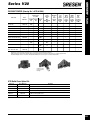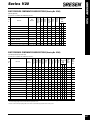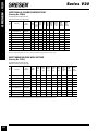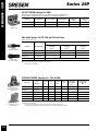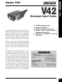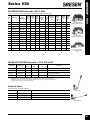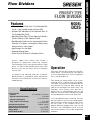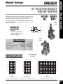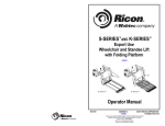
1
• Circuit and Outlet Conversion Information ..............340
• V10 Series ......................................................341 - 345
• V12 Series ......................................................347 - 350
• V20 Series ......................................................351 - 372
• 25P Series ......................................................373 - 378
• V42 Series ......................................................379 - 384
• V50 Series ......................................................385 - 388
• SP, SPK, & SSK Series ....................................389 - 391
• 300 & 400 Series ............................................392 - 393
• Solenoid Operated Directional Valves......................394
• Directional Control Valves (4-Way)..................395 - 396
• Float Position Valves ................................................397
• Selector Valves ................................................398 - 400
• Directional Control Valves ..............................401 - 402
• Unidirectional Valves ................................................403
• Check Valves ..................................................404 - 405
• Lock Valves ....................................................406 - 409
• Flow Dividers ..................................................410 - 417
• Flow Control Valves ........................................418 - 419
• Cushion Valves ................................................420 - 422
• Relief Valves ....................................................423 - 430
• Repair Parts & Seal Kits ..................................543 - 552
GRESEN® VALVE INDEX
Valves
GRESEN® VALVES
Valves
PARALLEL HYDRAULIC CIRCUITS
The most common type of hydraulic circuit is the parallel circuit. Refer to the parallel circuit diagram. With
all valve spools centered, the pump flow will return to
tank at low pressure through the open center bypass.
When a spool is actuated, the open center bypass is
blocked and the inlet is connected to one of the work
ports. The opposite work port will be connected to
tank, completing the circuit. If more than one valve
spool is shifted at the same time, the oil will follow the
path of least resistance and the hydraulic cylinder or
motor having the lightest load will begin to function
first.
If the spool of the cylinder or motor having the lightest load is metered (not fully shifted), then both may
be operated at the same time.
OUTLET CONVERSION PORT OPTIONS
The outlet conversion port is machined to accept the option plugs listed here:
Closed Center Plug (clsed center systems)
Install a closed center plug when using a variable displacement pump. The closed center plug will block
hydraulic pump flow when all valve spools are in neutral. High pressure is maintained at the control valve
inlet. The maximum system pressure is typically set with the compensator adjustment on the pump.
Power Beyond Sleeve (high pressure carry over)
By installing a power beyound sleeve, hydraulic oil under pressure will be carried thru the valve making it
available to a second control valve. In a power beyond circuit, the upstream valve will always have priority.
Hydraulic oil will only be available to the downstream valve when all the spools in the upstream valve are in
neutral. If the pressure requiements for both valves are the same, only one system relief valve is required. It
must be installed in the upstream valve. Each control valve may have its own relief valve set at a different
pressure, but the highest pressure setting must be in the upstream valve. When two valves are connected
together in this manner, each valve must have a return line to tank.
340
V10
GRESEN® - V10
Series V10
Directional Control Valves
Gresen‘s Model V10 sectional directional
control valves provide parallel or tandem
circuit operation for open center and
closed center systems. They offer economy and excellent performance in a
compact design.
Nominal Flow Rating
1
Specifications
. . . . . . . . . . . . . . . . . . .15 GPM (56,7 liters/min)
Operating Pressure (maximum)
Continuous Operating . . . . . . . . . . . . . . . . . . . . . .3500 PSI (242 bar)
Work Port . . . . . . . . . . . . . . . . . . . . . . . . . . . . . . .5000 PSI (345 bar)
Exhaust Core . . . . . . . . . . . . . . . . . . . . . . . . . . . . .500 PSI (34,5 bar)
Operating Temperature . . . . . . . . . . . .-40°F (-40°C) to +200°F (+93°C)
Standard Port Sizes 2
Inlet . . . . . . . . . . . . . . . . . . . . . . . . . . . . . . . . . . . . . . . . . . . .SAE 10
Outlet . . . . . . . . . . . . . . . . . . . . . . . . . . . . . . . . . . . . . . . . . . .SAE 10
Power Beyond . . . . . . . . . . . . . . . . . . . . . . . . . . . . . . . . . . . . .SAE 10
Work Ports (Manual and Solenoid Work Sections) . . . . . . . . . . .SAE 8
■ Parallel and Tandem work sections with individual load (reverse flow) checks
■ Available for open center, closed center and
power beyond applications
■ Low flow and high flow spool options available
offering flows to 15 GPM (45 lpm).
■ Continuous system operating pressures to 3500
PSI (Work port pressures to 5000 PSI)
■ Utilizes many common components such as
relief valves, spool positioners and handles with
Models V11 and V16
■ 3-Way, 4-Way, and 4-Way Float operation
■ Numerous manual spool positioner options plus
remote hydraulic or electric solenoid operation
■ Work Port relief valves and anti-cavitation check
valves available
■ Single handle or dual function mechanical
joystick control of manual sections
■ Enclosed spool ends with handles
■ Long life - low friction spool seals
Fluid Compatibility
Petroleum Based . . . . . . . . . . . . . . . . . . . .60-1000 SSU (10-216 cST)
O-Ring Seals . . . . . . . . . . . . . . . . . . . .Buna-N Standard (Optional Viton)
Spool Seals . . . . . . . . . . . . . . . .Lip Type (Standard in 24990 Housings)
O-Rings (Standard in 23592 Housings)
Filtration Required . . . . . . . . . . . . . . . . . . . . .10 micrometers (nominal)
Number of Work Sections . . . . . . . . . . . . . . . . . . . . . . . . . . . . . . . . .1-9
Weight (approx.)
No. 23613 Inlet Cover . . . . . . . . . . . . . . . . . . .Approx. 5 lbs. (2,3 kg)
No. 23627 Outlet Cover . . . . . . . . . . . . . . . . . .Approx. 5 lbs. (2,3 kg)
No. 24990 Work Section (Manual) . . . . . . . . . .Approx. 6 lbs. (2,8 kg)
No. 23962 Work Section (Solenoid) . . . . . . . .Approx. 8.5 lbs. (3,8 kg)
Mounting Position . . . . . . . . . . . . . . . . . . . . . . . . . . . . . .Not Restricted
See Page 326 For Ordering Information
341
GRESEN® - V10
Series V10
V10 INLET COVERS (Housing No. 23613)
Item
No.
23613 Left Cover
1
Model
Number
Part
Number
End
Inlet
End
Outlet
Top
Inlet
Top
Outlet
SAE 10
•
1
10-LC-10
13650709
•
•
•
•
2
10-LC-8
13650710
•
•
•
•
3
10-LC-10-PRV
26157001
•
•
Pressure
Reducing
Valves 1
SAE 8
List
Price
57.00
•
55.00
•
•
177.10
All inlet covers machined to accept main relief cartridges. Two SAE port plugs are furnished loose with Items 1 and 2.
Used for Solenoid Valve Assemblies. Only top ports are available with this cover.
Main Relief Cartridges for Inlet Covers
Item
No.
No Relief Cavity Plug
Model
Number
Part
Number
500-1249
Set @ 1200
PSI c/p
•
1
RCM-1200
13650712
2
RCM-1700
13650713
3
RCM-1950
13650714
4
RCM-2550
13650715
5
RCM-3000
13650716
6
RCM-3500
13650774
7
K-10-NR
13650718
1250-1749
Set @ 1700
PSI c/p
Pressure Range and Setting
1750-1999 2000-2599
2600-3000 3001-3500 Externally
Set @ 1950 Set @ 2550 Set @ 3000 Set @ 3500 Adjustable
PSI c/p
PSI c/p
PSI c/p
PSI c/p
PSI c/p
List
Price
36.10
•
36.10
•
36.10
•
36.10
•
36.10
•
36.10
No Relief Cavity Plug for V10 Inlet Covers
10.80
Model RCM relief cartridges are internal shim adjustable.
Relief External Adjustment Kit
Item
No.
Model
Number
Part
Number
Description
List
Price
1
K-WH-A
8650381
External Screw Adjustment Option for RCM Relief Cartridges
15.60
External Adjustment Kit
V10 OUTLET COVERS (Housing No. 23627)
Item
No.
23627 Outlet Cover
Model
Number
Part
Number
SAE 8
•
SAE 10
Top Outlet
End Outlet
Machined
for Power
Beyond
With Mechanical
Pressure Control
Cartridge 1
List
Price
1
10-RC-8-EY
13650719
•
•
•
41.60
2
10-RC-10-EY
13650720
•
•
•
•
43.70
3
10-RC-10-P-MECH 26157002
•
•
•
•
105.40
All outlet covers machined to accept (top) Option Cartridges. Two SAE port plugs furnished loose with each cover.
1
Used for Solenoid Valve Assemblies.
The pressure control cartridge must be located in the downstream valve if using the optional power beyond feature in
the solenoid-operated upstream valve.
Outlet Cover Conversion Kits
Item
No.
Closed Center Plug
Model
Number
Part
Number
Description
List
Price
15.50
1
K-10-C
13650722
Closed Center Plug
2
K-10-8-Y
13650723
SAE 8 Power Beyond Sleeve
13.40
3
K-10-10-Y
13650724
SAE 10 Power Beyond Sleeve
13.40
4
K-10-P (MECH)
26157055
Pilot Control Cartridge (for Solenoid Valves)
56.50
The power beyond sleeves listed here are required for (top) power beyond port only.
To power beyond out the (end) of the valve, requires installation of the K-10-C plug in the (top) option port. Refer to the V10 Service Manual for
procedures on selecting Closed Center and Power Beyond options.
342
V10 Parallel Work Sections with Machined Upper Option Cavities (Housing No. 24990)
Item
No.
1
2
3
4
5
6
Model
Number
Part
Number
SAE 8
[8]
10-08-03
10-08-R3
10-08-04
10-08-F4
10-08-DF4
10-08-K4
13650776
13650971
13650973
13650975
13650977
13650979
•
•
•
•
•
•
3-Way
3-Pos
[3]
4-Way
3-Pos
[4]
4-Way
3 -Pos
Free
Flow
[F4]
4-Way
4-Pos
Float
[K4]
•
•
Spring
Return to
Neutral
[0]
3-Pos
Detent
[D]
1-Pos.
Detent
(Spool In)
[R]
List
Price
•
119.40
156.70
113.30
122.00
141.70
149.20
•
•
•
•
•
•
•
•
24990 Work Section
GRESEN® - V10
Series V10
The work sections listed above all have the upper work port relief option cavities machined and plugged.
V10 work sections do not include handles or brackets. They are supplied (LCHA) Less Complete Handle Assembly.
V10 Parallel Work Sections Without Upper Option Cavities (Housing No. 24990)
Item
No.
1
2
3
4
5
6
Model
Number
10-08-N-03
10-08-N-R3
*10-08-N-04
10-08-N-F4
10-08-N-DF4
10-08-N-K4
Part
Number
SAE 8
[8]
13650726
13650970
13650972
13650974
13650976
13650978
•
•
•
•
•
•
3-Way
3-Pos
[3]
4-Way
3-Pos
[4]
4-Way
3 -Pos
Free
Flow
[F4]
4-Way
4-Pos
Float
[K4]
•
•
Spring
Return to
Neutral
[0]
3-Pos
Detent
[D]
1-Pos.
Detent
(Spool In)
[R]
•
•
•
•
•
•
•
•
•
List
Price
99.20
136.50
93.10
101.80
121.50
129.00
The ‘N’ in the work sections listed above designates that the upper work port relief option cavities are NOT machined. If the application
requires the use of work port option cartridges, (i.e. reliefs or anti-cavitation checks), do not select work section from this group.
V10 work sections do not include handles or brackets. They are supplied (LCHA) Less Complete Handle Assembly.
V10 Tandem Work Sections with Machined Upper Option Cavities (Housing No. 24990)
Item
No.
1
2
3
4
5
6
Model
Number
Part
Number
SAE 8
[8]
10T-08-03
10T-08-R3
10T-08-04
10T-08-F4
10T-08-DF4
10T-08-K4
13650782
13650981
13650983
13650985
13650987
13650989
•
•
•
•
•
•
3-Way
3-Pos
[3]
4-Way
3-Pos
[4]
4-Way
3 -Pos
Free
Flow
[F4]
4-Way
4-Pos
Float
[K4]
•
•
Spring
Return to
Neutral
[0]
3-Pos
Detent
[D]
1-Pos.
Detent
(Spool In)
[R]
•
•
•
•
•
•
•
•
•
List
Price
127.10
164.40
120.90
129.60
149.40
156.90
The work sections listed above all have the upper work port relief option cavities machined and plugged.
V10 work sections do not include handles or brackets. They are supplied (LCHA) Less Complete Handle Assembly.
V10 Tandem Work Sections Without Upper Option Cavities (Housing No. 24990)
Item
No.
1
2
3
4
5
6
Model
Number
10T-08-N-03
10T-08-N-R3
10T-08-N-04
10T-08-N-F4
10T-08-N-DF4
10T-08-N-K4
Part
Number
SAE 8
[8]
13650738
13650980
13650982
13650984
13650986
13650988
•
•
•
•
•
•
3-Way
3-Pos
[3]
4-Way
3-Pos
[4]
4-Way
3 -Pos
Free
Flow
[F4]
4-Way
4-Pos
Float
[K4]
•
•
Spring
Return to
Neutral
[0]
3-Pos
Detent
[D]
1-Pos.
Detent
(Spool In)
[R]
•
•
•
•
•
•
•
•
•
List
Price
106.90
144.20
100.70
109.40
129.20
136.70
24990 Work Section
The ‘N’ in the work sections listed above designates that the upper work port relief option cavities are NOT machined. If the application
requires the use of work port option cartridges, (i.e. reliefs or anti-cavitation checks), do not select work section from this group.
V10 work sections do not include handles or brackets. They are supplied (LCHA) Less Complete Handle Assembly.
343
GRESEN® - V10
Series V10
V10 ‘Parallel’ Solenoid-Operated Work Sections with Machined Upper Option Cavities
(Housing No. 23962)
4-Way
3-Pos
[4]
4-Way
3 -Pos
Free
Flow
[F4]
Item
No.
Model
Number
Part
Number
SAE 8
[8]
3-Way
3-Pos
[3]
1
10-08-03-SOL-I-12
26157003
•
•
2
10-08-03-EPC-I-12
26157005
•
•
3
10-08-04-SOL-I-12
26157007
•
•
4
10-08-04-EPC-I-12
26157009
•
•
5
10-08-F4-SOL-I-12
26157011
•
•
6
10-08-F4-EPC-I-12
26157013
•
•
12 VDC
On/Off
Solenoid
[SOL-I-12]
12 VDC
Proportional
Solenoid
[EPC-I-12]
List
Price
•
440.20
•
547.10
•
434.10
•
541.00
•
442.80
•
549.70
The solenoid-operated work sections listed above all have the upper work port relief option cavities machined and plugged.
These sections do NOT offer the handle override feature. Contact the Gresen factory in Minneapolis for solenoid sections with handle.
Solenoid Cartridges & Coil Kits
Refer to page 104 in the Electronics Section
V10 Spool Positioner Option Kits
Model
Number
Part
Number
1
K-10-A
13650746
Spring Extended Spool Positioner 1
24.20
2
K-V10-A
26157056
Spring Extended Spool Positioner (For Use With 24990 Housing) 1
24.20
3
K-10-D
13650747
3-Position, ‘D’ Detent Spool Positioner
29.10
4
K-V10-D
26157057
3-Position, ‘D’ Detent Spool Positioner (For Use With 24990 Housing)
29.10
5
K-10-M
13650748
Manual ‘M’ Spool Positioner
23.10
6
K-V10-M
26157058
Manual ‘M’ Spool Positioner (For Use With 24990 Housing)
23.10
7
K-10-S
13650749
Spring Center to Neutral Spool Positioner
26.00
8
K-V10-S
26157059
Spring Return to Neutral Spool Positioner (For Use With 24990 Housing)
26.00
47.60
Item
No.
Positioner Kit
List
Price
Description
9
K-10-RI
13650750
1-Position, ‘R’ Detent Spool ‘IN’ with Spring return to Neutral
10
K-V10-RI
26157060
1-Position, ‘R’ Detent Spool ‘IN’ with Spring return to Neutral
11
K-10-RO
13650751
1-Position, ‘R’ Detent Spool ‘OUT’ with Spring return to Neutral
12
K-V10-RO
26157061
1-Position, ‘R’ Detent Spool ‘OUT’ with Spring return to Neutral (For Use with 24990 Housing) 2
47.60
2
48.40
48.40
The Above K-V10-(Kits) are for use with the new style 24990 work section housings. The internal working parts are NOT interchangeable
with the equivalent K-10-(Kits).
1
2
K-10-A and K-V10-A Spool Positioners holds the spool in the ‘B’ port power (Spool Out) position and will limit the shifting of the spool to the neutral
position only.
K-10-RO and K-V10-RO Spool Positioner detent sleeve may be reversed for ‘RIO’ (Detent ‘In’ and ‘Out’) applications.
Refer to the V10 Service and Parts manual for procedures.
V10 Mechanical Joysticks
Fits V10 ‘24990’ Work Section Housings. Includes two Spool Clevis Adapters.
Item
No.
Model
Number
Part
Number
1
MJA2-10L-NB
13650968 1
V10 Mechanical Joystick, ‘LH’ Assembly
148.90
2
MJA2-10R-NB
13650969
1
V10 Mechanical Joystick, ‘RH’ Assembly
148.90
3
K-MJA-O
13650691
Mechanical Joystick ‘Offset’ Handle Assembly
25.80
4
K-MJA-S
13650690
Mechanical Joystick ‘Straight’ Handle Assembly
22.60
1
344
Includes boot assembly.
Description
List
Price
Handle Option Kits
Item
No.
Model
Number
Part
Number
List
Price
Description
1
K-10-UBH
26157100
20.50
2
K-10-VH
13650752
Vertical Handle Assembly
3
K-10-HH
13650753
Horizontal Handle Assembly
34.70
4
K-10-VH-EXT
13650786
Extended Vertical Handle Kit - For use in V10/V11 valves using
port reliefs on handle end
46.40
5
K-10-HH-EXT
13650948
Extended Horizontal Handle Kit - For use in V10/V11 valves using
port reliefs on handle end
46.40
6
K-10-UH-BOOT
26157101
Extended Vertical
Handle Assembly
34.70
GRESEN® - V10
Series V10
Vertical Handle Assembly
5.20
Refer to Model V10 Service Catalog No. GSD-1010 for information regarding handle installation.
Horizontal Handle Assembly
Section Stud Assembly Kits
Item
No.
Model
Number
Part
Number
1
List
Price
Description
Spacer for Older Handles
6.50
2
K-10-1
13650755
Stud Kit for One (1) Work Section
26.70
3
K-10-2
13650756
Stud Kit for Two (2) Work Sections
26.70
4
K-10-3
13650757
Stud Kit for Three (3) Work Sections
26.70
5
K-10-4
13650758
Stud Kit for Four (4) Work Sections
26.70
6
K-10-5
13650759
Stud Kit for Five (5) Work Sections
26.70
7
K-10-6
13650760
Stud Kit for Six (6) Work Sections
29.60
8
K-10-7
13650761
Stud Kit for Seven (7) Work Sections
29.60
9
K-10-8
13650762
Stud Kit for Eight (8) Work Sections
29.60
10
K-10-9
13650763
Stud Kit for Nine (9) Work Sections
29.60
11
K-10-10
13650764
Stud Kit for Ten (10) Work Sections
29.60
12
K-10-11
13650765
Stud Kit for Eleven (11) Work Sections
29.60
13
K-10-SECT-SEAL
13650767
Section Seal Kit
14
K-10-SOL-BRACKET 26157088
(Tall) Mounting Bracket - For use with V10 Solenoid Valve Assemblies
23.70
15
K-10-SOL-SEAL
Section Seal for Solenoid Pilot Passage (25 pieces of 21866001 Seal).
29.50
26157030
Assembly Stud Kit
3.30
Each Stud Kit includes (4) Studs, (8) Nuts, (2) Mounting Brackets and the required number of Section Seals.
Work Port Relief/Anti-Cav Options
Item
No.
Model
Number
Part
Number
1
K-10-AC
13650770
2
RP10A-3000
13650768
3
RP10N-3000
13650769
4
RP10A-AC 3000
13650771
5
RP10N-AC 3000
13650772
(A)
Screw
Adjustable
(N)
Non-Adj.
Tamper
Resistant
Anti-Cav
Check
Relief Valve
Relief Valve
A/C Check
500-5000
Set @ 3000
PSI c/p
List
Price
•
•
•
•
•
RP10A Relief Cartridge
39.80
•
•
38.30
•
•
38.30
•
•
49.30
•
•
49.30
Model RP10A (-AC) relief cartridges are externally adjustable. Model RP10N (-AC) relief cartridges are preset at specified setting and offer a
‘tamper resistant’ cover.
Work Port No Relief ‘NR’ Plug Kit
Item
No.
Model
Number
Part
Number
1
K-10-NR-WP
13650773
Description
Work Port Relief Cavity ‘NR’Plug (Not for use in V10 Inlet Covers)
List
Price
No Relief Cavity Plug
10.80
345
ntertech Cylinders, Pumps & Motors / Custom Hoists / LHA
Accessories / Cylinders / Prince Cylinders & Pumps / Chief
Cylinders / Perfection Pumps / White Motors / Gresen®
Cylinders, Pumps, Motors & Valves / Commercial Intertech
Cylinders, Pumps & Motors / Custom Hoists / LHA Accessories
Cylinders / Prince Cylinders & Pumps / Chief Cylinders /
Perfection Pumps / White Motors / Gresen® Cylinders, Pumps,
Motors & Valves / Commercial Intertech Cylinders, Pumps &
Motors / Custom Hoists / LHA Accessories / Cylinders / Prince
Cylinders & Pumps / Chief Cylinders / Perfection Pumps / White
Motors / Gresen® Cylinders, Pumps, Motors & Valves /
Commercial Intertech Cylinders, Pumps & Motors / Custom
Hoists / LHA Accessories / Cylinders / Prince Cylinders &
Pumps / Chief Cylinders / Perfection Pumps / White Motors /
Gresen® Cylinders, Pumps, Motors & Valves / Commercial
ntertech Cylinders, Pumps & Motors / Custom Hoists / LHA
Accessories / Cylinders / Prince Cylinders & Pumps / Chief
Cylinders / Perfection Pumps / White Motors / Gresen®
Cylinders, Pumps, Motors & Valves / Commercial Intertech
Cylinders, Pumps & Motors / Custom Hoists / LHA Accessories
Cylinders / Prince Cylinders & Pumps / Chief Cylinders /
®
V12
Directional Control Valves
GRESEN® - V12
Series V12
■
■
■
■
12 GPM nominal flow rating
Pressures to 3000 PSI
Lock-out sections available
High and Low profile sections allow you
to use workport options only on those
sections that require them
■ Manual or solenoid actuator options
Gresen’s Model V12 Directional Control
Valve is designed for parallel hydraulic
circuit applications, up to 3000 PSI
(207 bar) continuous operating pressure.
Each valve stack consists of an inlet
cover, one or more work sections and an
outlet cover. A variety of work sections,
spools, spool actions, end covers and
relief combinations are available to
provide the exact type of valve assembly
required for any given application
whether mobile, industrial or agricultural.
Specifications
Pressure Rating:
Continuous Operating, Max. . . . . . . . . . . .3000 PSI (207 bar)
Tank Port (Exhaust), Max. . . . . . . . . . . . . .500 PSI (34,5 bar)
Capacity:
Nominal Flow . . . . . . . . . . . . . . . . . .12 GPM (45,4 litres/min)
Operating Temperature: . . . . . . . .-40°F (-40°C) to 176°F (80°C)
Port Size:
Inlet . . . . . . . . . . . . . . . . . . . . . . . . . . . . . . . . . . . . . .SAE 10
Outlet . . . . . . . . . . . . . . . . . . . . . . . . . . . . . . . . . . . . .SAE 10
Work Ports . . . . . . . . . . . . . . . . . . . . . . . . . . . . . . . . . .SAE 8
Power Beyond . . . . . . . . . . . . . . . . . . . . . . . . .SAE 8, SAE 10
Filtration Required (Min.) . . . . . . . . . . . . . . . . .33 micrometre
Weight:
Inlet Cover . . . . . . . . . . . . . . . . . . . .Approx. 3.3 lbs. (1,5 kg)
Outlet Cover . . . . . . . . . . . . . . . . . . .Approx. 3.3 lbs. (1,5 kg)
Work Sections:
Standard . . . . . . . . . . . . . . . . . . . . .Approx. 5 lbs. (2,3 kg)
Accessory . . . . . . . . . . . . . . . . . . .Approx. 6.5 lbs. (2,7 kg)
See Page 326 For Ordering Information
347
GRESEN® - V12
Series V12
LEFT COVER
Bill of Material #
SAE 10
Port Size
[2]
V12P-2UNB
8650-584
•
V12P-1UNB
8650-974
Order Code
V12P Left Cover
SAE 8
Port Size
[1]
•
Top &
End Inlet
[U]
Plastic Relief
Cavity Plug
[N]
Relief
Position "B"
[B]
•
•
•
•
•
•
Note: All Left Covers are machined to accept Main Relief Cartridge.
Main Relief Options
Includes all necessary seals.
Order Code
Model CRV-15B
Pilot Operated Relief
Valve Cartridge
Bill of Material #
Description
RCP-15A
8650-585
No Relief Plug Kit (NR Option)
CRV-15B-2500
8650-586
Pilot Operated Relief Valve Cartridge set at 2500 PSI. Crack at 1 GPM
CRV-15F-2500
8650-608
Direct Acting Relief Valve Cartridge set at 2500 PSI. Crack at 1 GPM
Above Relief Valves are screw adjustable from 500 to 3000 PSI.
RIGHT COVER
Bill of Material #
SAE 10
Port Size
[2]
V12E-2UO
8650-587
•
V12E-1UO
8650-972
Order Code
V12E Right Cover
SAE 8
Port Size
[1]
Top &
End Outlet
[U]
Machined from
Opened Center
[O]
•
•
•
•
•
Open Center port may be converted to Closed Center or Power Beyond using Option Kits below.
Right Cover Option Kits
Order Code
348
Bill of Material #
Description
CBP-15C
8650-588
Closed Center Plug
PBS-15N
8650-589
SAE 8 Power Beyond Sleeve
PBS-15P
8650-590
SAE 10 Power Beyond Sleeve
WORK SECTIONS
Item
No.
Order Code
Bill of Material
#
Spring
Centered
[C]
4-Way
3-Position
[A]
3-Way
3-Position
[E]
4-Way
4-Position
Float
[F]①
1
V12W-1FBC-ES
8650-591
•
•
2
V12W-1FBC-ERNN
8650-971
•
•
3
V12W-1FBC-AS
8650-593
•
•
4
V12W-1FBC-ARNN
8650-970
•
•
5
V12W-1FBC-JS
8650-806
•
6
V12W-1FBC-FS①
8650-973
•
•
7
V12W-1FBC-FRNN①
8650-969
•
•
8
V12W-1FBC-JLEE
8650-807
•
4-Way
3-Position
Free Flow Spool
[J]
Standard
Low
Section
[S]
Relief
Option Section
[R*]
Lockout Option
Section
[L**]
•
•
GRESEN® - V12
Series V12
•
•
•
•
•
•
•
•
Note: All work ports are SAE 8.
All spools include female spool end located on “B” port end - Handle bracket and handle assembly not included.
*All relief option sections [R] include machined and plugged (plastic plugs) work port options [NN].
**All lockout option sections [L] include cylinder lock valves [EE].
①Float Section(s) must be stacked next to the Inlet Cover to allow proper operation.
Relief Option Section
[R]
Lockout Option Section
[L]
Standard Low Section
[S]
Handle End Options
Handle Kit includes necessary hardware.
Order Code
LVR-15-HDA
Bill of Material #
8650-598
Description
Vertical Handle (includes bracket)
Vertical Handle
349
GRESEN® - V12
Series V12
Section Stud Assembly Kits
Includes Section Seals and Nuts.
Order Code
Bill of Material #
Number of Work Stations
TRK-15-3*
8650-599
One Section
TRK-15-4*
8650-600
Two Section
TRK-15-5*
8650-601
Three Section
TRK-15-6*
8650-602
Four Section
TRK-15-7*
8650-603
Five Section
TRK-15-8*
8650-604
Six Section
TRK-15-9*
8650-605
Seven Section
TRK-15-10*
8650-606
Eight Section
*Total number of sections including inlet, work section(s) and outlet.
Spool Positioner Option Kit
Order Code
Bill of Material #
K-12-D
Description
8650-607
3-Position Detent
Note: Cannot be used on Float Spool.
Spool Action Assembly
(Bonnet)
Work Port Option Kits
Includes all necessary seals.
Bill of Material #
Pressure Range
PSI 500 to 3000
Set at 2500
CRV-15F-2500
8650-608
•
Direct Acting Relief
CRV-15B-2500
8650-586
•
Pilot Operated Relief
CRV-15C-2500
8650-609
•
Combination Relief & Anti-Cav
CRA-15H
8650-610
Anti-Cavitation Check
RCP-15A
8650-585
No Relief Plug Kit (NR Option for “R” Body)
LCP-15P
8650-612
Lock Cavity Plug (for “L” Body)
Order Code
Model CRV-15B
Pilot Operated Relief
Valve Cartridge
Note: All above Relief Valves are screw adjustable.
Crack Pressure set at 1 GPM.
350
Description
V20
Directional Control Valves
GRESEN® - V20
Series V20
Specifications
Gresen’s Model V20 Directional Control Valves are
available for open center or closed center systems.
Open center models are available for parallel, tandem,
combined parallel/tandem or series circuits. Closed
center models are available for constant pressure or
load sensing parallel circuits.
Optional Reduced Pressure Drop work sections are
available for parallel or tandem open center circuits.
The wide variety of circuit options and excellent performance provided by Model V20 make it ideally suited for back hoe, front end loader and personnel lift
applications.
■
■
■
■
Minimal spool actuating effort - Maximum, 50 pounds [22,6 kg] at the spool
Improved, extra-fine metering
Minimum pressure drops through open center and through work ports
Float section may be installed at any point within the valve assembly
Open Center System
Model
V20P
V20T
V20PT
V20S
V20C
Hydraulic oil is directed from the inlet port, through the open center core to the
outlet port of the Directional Control Valve when all spools are in the neutral position. Shifting the valve spool directs oil flow to the desired work port.
Parallel Circuit
Tandem Circuit
Parallel/Tandem Circuit
Series Circuit
Closed Center System
Model
Pressure Rating:
Continuous Operating, Max. . . . . . . . . . . .3500 PSI (242 bar)
Capacity:
Nominal Flow . . . . . . . . . . . . . . . . . . .20 GPM (76 litres/min)
Maximum Flow . . . . . . . . . . . . . . . . .30 GPM (114 litres/min)
Operating Temperature: . . . . . . . .-40°F (-40°C) to 176°F (80°C)
Filtration Required (Min.) . . . . . . . . . . . . . . . . .33 micrometre
Weight:
Inlet Cover . . . . . . . . . . . . . . . . . . . . . .Approx. 6 lbs. (2,7 kg)
Outlet Cover . . . . . . . . . . . . . . . . . . .Approx. 31/2 lbs. (1,6 kg)
Work Sections, Each . . . . . . . . . . . . . .Approx. 9 lbs. (4,10 kg)
Maximum Exhaust Core Pressure:
With Handle Bracket or Heavy Duty
Spool Seal Retainer Installed
Continuous Operating . . . . . . . . . . . . . . . . .500 PSI (34,5 bar)
Intermittent Peak . . . . . . . . . . . . . . . . . . .1000 PSI (69,0 bar)
With Standard Spool Seal Retainer
Installed . . . . . . . . . . . . . . . . . . . . . . . . . . . . .200 PSI (13,8 bar)
Constant PressureParallel Circuit
Maximum circuit pressure is limited by the main relief valve, which relieves into
the exhaust core.
In a neutral position, open center systems operate at full flow and at low pressure
The Model V20C work section has no open center core. Pump flow is blocked by the
valve when the valve spool is in neutral position. Shifting the valve spool directs the
oil flow to the desired work port.
A pump that varies the output flow and maintains a pre-determined output pressure
is required for this type of circuit. Closed center systems typically operate at minimum flow and at high pressure standby when the valve spool is in the neutral position. The only flow required is that which will compensate for internal losses or for
other system requirements.
351
GRESEN® - V20
Series V20
V20 LEFT COVERS (Housing No.'s 8398 & 7736)
Order Code
8398 Left Cover
Bill of
Material #
End
Inlet
Top
Inlet
End
Outlet
Top
Outlet
20-LC-75
8650-030
•
•
•
•
20-LC-12
8650-029
•
•
•
•
20-LC-12-FC
8650-028
•
•
•
Port Size
SAE 12
[12]
Port Size
3/4" NPT
[75]
With 4-25 GPM
Flow Control
To Allow Use
of Excess Flow
[FC]
•
•
•
•
•
Note: All the above inlet covers are machined to accept the main relief cartridges listed below.
Two port plugs are furnished loose with each cover, one is machined for 1/4" NPTF gauge port.
Excess flow plug is furnished with all 7736 housings.
7736 Left Cover
Main Relief Options for V20 Inlet Covers
All set at “crack” pressure of 1 GPM.
Bill of
Material #
500-1249
Set @ 1200
PSI c/p
WH-1200
8650-417
•
WH-1700
8650-418
WH-1950
8650-419
Order Code
Model WH
Relief Valve Cartridge
Model RP51
Relief Valve Cartridge
WH-2550
8650-420
RP51A-3000
8650-421
K-20-NR
8650-382
1250-1749
Set @ 1700
PSI c/p
1750-1999
Set @ 1950
PSI c/p
2000-2599
Set @ 2550
PSI c/p
•
•
•
•
Relief Plug Kit
(NR Option)
Note: All above Relief Valves have stainless steel springs.
WH Relief Valves are internal shim adjustable.
RP51A Relief Valves are external screw adjustable.
Relief Option Kit
Order Code
K-WH-A
352
Bill of Material #
8650-381
500-3500
Set @ 3000
PSI c/p
Description
Screw Adjustable Option for WH Relief
V20 RIGHT COVERS (Housing No.’s 6770 & 8644)
Outlet Port Size
& Location
Order Code
Bill of
Material #
20-RC-75-E
3/4" NPT
[75]
SAE 10
[10]
SAE 12
[12]
13650-147
END
20-RC-75-E-MY
8650-027
END
20-RC-10-E
13650-145
20-RC-12-E
13650-146
END
20-RC-12-E-MY
8650-024
END
Includes
Load
Sense
Option
Includes
Bleed-off
[LS]
Includes
12VDC
On-off
Pressure
Control
Cartridge
[PC]
24VDC
On-off
Pressure
Control
Cartridge
[PC]
SAE 4
Load
Sense
Port & Pilot
Seal C’bores
[P-NB]
•
8650-025
END
20-RC-12-E-PC-SOL-12①
8650-026
END
20-RC-12-E-PC-SOL-24
13650-307
20-RC-75-ET-75-MY
8650-023
20-RC-12-E-LS-P-NB
(NB = No bleed off)②
Machined
for
Power
Beyond
[MY]
END
20-RC-12-E-LS
20-RC-12-ET-12-MY
Top
Power
Beyond
Port
[MY]
(8644 Housing
Only)
GRESEN® - V20
Series V20
•
•
•
END
END &
TOP
8650-022
END &
TOP
13650-169
•
3/4"
NPT
•
SAE
12
•
END
•
NOTE: A 3/4" NPT or SAE 12 Plug will be shipped with all 8644 Outlet Covers to plug either the outlet port or power beyond port if either is not required.
Plugging top power beyond port will convert valve to closed center unless internal plug is removed.
①This cover must be used in the downstream valve if a power beyond sleeve is used in the utility section of a solenoid upstream valve.
②No Bleed Off (NB) cannot be converted to Bleed Off. Bleed Off Covers, however, may be converted to No Bleed Off.
8644 Right Cover
Right Cover with
Pressure Control
Cartridge
6770 Right Cover
6770 Outlet Cover Option Kits
Order Code
K-20-C
Bill of Material #
8650-099
Description
Closed Center Plug
K-20-X
8650-100
Conversion Plug
K-20-50-Y
8650-101
1/2" NPT Power Beyond Sleeve
K-20-08-Y
8650-102
SAE 8 Power Beyond Sleeve
K-20-10-Y
8650-103
SAE 10 Power Beyond Sleeve
NOTE: These option kits may not be used with 6770 LS (Load Sense) or 8644 covers.
353
GRESEN® - V20
Series V20
V20 PARALLEL WORK SECTIONS (Housing No. 8072)
Bracket Assembly included. Includes load checks where applicable.
Bill of
Material #
4-Way
3-Pos.
[4]
1 20-50-04
2 20-08-04
8650-021
13650-148
•
•
3 20-10-04
8650-020
•
Item
No.
Order Code
3-Way
3-Pos.
[3]
4-Way
3-Pos.
Free
Flow
Spool
[F]
4-Way
4-Pos.
Float
Assembly
[K4]
1/2"
NPT
Work
Ports
[50]
SAE 8
Work
Ports
[08]
SAE 10 Spring
Return
Work
to
Ports
Neutral
[10]
•
•
8650-019
•
5 20-08-F4
13650-151
•
6 20-10-F4
8650-018
7 20-50-03
8650-017
8 20-08-03
13650-149
•
9 20-10-03
8650-016
•
•
•
•
8650-015
•
•
8650-014
8650-013
•
14 20-10-04-SOL-E-24
13650-279
•
15 20-10-03-SOL-E-12
13650-280
16 20-10-03-SOL-E-24
13650-278
17 20-10-04-HRO*
8650-578
•
•
18 20-10-KO4-2000
8650-011
•
•
19 20-10-W4*
8650-010
•
•
8650-009
8650-638
•
•
•
•
13 20-10-04-SOL-E-12
21 20-10-W4-SS*
•
•
•
•
•
•
•
•
•
•
•
•
•
•
•
•
•
•
•
•
•
•
•
•
•
•
•
22 20-10-WF4-SS*
8650-639
•
•
23 20-10-F4-SOL-E-24
13650-530
•
•
24 20-10-F4-SOL-E-12
13650-529
•
25 20-08-DF4
13650-838
•
•
•
•
•
•
*Bracket Assembly not furnished with Rotary Spool Option (W) Items 19, 21 & 22 or Hydraulic Remote Spool Actuator (HRO) Item 17.
Model V20P
354
24 VDC
Solenoid
(External
Pilot
Design)
[SOL-E]
•
12 20-10-K4
20 20-10-DF4
Stainless
Steel
Spool
[SS]
•
•
13650-150
3-Pos.
Detent
[D]
•
•
11 20-08-K4
Rotary
Spool
Actuator
[W]
•
•
10 20-50-K4
Hydraulic
Remote
Spool
Actuator
[HRO]
•
•
•
12VDC
Solenoid
(External
Pilot
Design)
[SOL-E]
•
•
•
4 20-50-F4
Internal
Hydraulic
Detent
Release
Set @
2000 PSI
[KO]
Solenoid Control
(SOL-E)
8072 & 10954
Hydraulic Remote Control
(HRO)
GRESEN® - V20
Series V20
V20RP PARALLEL WORK SECTIONS (Housing No. 10954)
Bracket assembly included. Includes load checks where applicable.
Bill of
Material #
Reduced
Pressure
Drop
Section
[RP]
SAE 10
Ports
[10]
1 20R-10-R3
13650-855
•
•
•
2 20R-10-03
13650-856
•
•
•
•
3 20R-12-03
13650-857
•
•
•
•
4 20R-12-R3
13650-858
•
•
•
5 20R-10-04
8650-613
•
Item
No.
Order Code
6 20R-12-04
13650-859
•
7 20R-10-F4
13650-276
•
8 20R-12-F4
13650-860
•
9 20R-10-DF4
13650-861
•
10 20R-10-K4
SAE 12
Ports
[12]
3-Way
3-Pos
[3]
•
4-Way
3-Position
[4]
4-Way
4-Way
4-Way
3-Position 4-Position Spring
3-Position
Detent Free
Return to
Float
Free Flow
Flow
Neutral
[K]
[F4]
[DF]
•
•
•
•
•
•
•
•
•
•
•
13650-862
•
•
11 20R-10-04-PILOT 13650-863
•
•
Model V20R
10954 Section)
•
•
•
Internal
Pilot
ThruPassage
[PILOT]
"R" Type
Detent
[R]
•
•
•
•
•
NOTE: The "Pilot" code designates that the internal pilot through-passages have been machined for use when intermixing solenoid and manual sections.
V20T and V20RT TANDEM WORK SECTIONS (Housing No.’s 8112 & 10762)
Item
No.
Order Code
Bill of
Material #
Tandem
Circuit
Section
[T]
Reduced
Pressure
Drop
Section
[RT]
SAE 10
Ports
[10]
SAE 12
Ports
[12]
3-Way
3-Position
[3]
4-Way
3-Position
[4]
Spring
Return to
Neutral
4-Way
4-Way
3-Position 4-Position
Free Flow
Float
[F4]
[K]
"R" Type Detent
[R]
1 20T-10-03
13650-851
•
•
•
2 20T-10-R3
13650-852
•
•
•
•
3 20RT-12-R3
13650-853
•
•
•
•
•
•
4 20T-10-04
8650-008
•
•
•
5 20RT-10-04
8650-614
•
•
•
•
6 20RT-10-K4
13650-854
•
•
7 20RT-10-04PILOT
13650-943
•
•
Model V20T
(8112 Section)
•
•
•
Model V20RT
(10762 Section)
NOTE: V20T and V20RT (Tandem) sections may be stacked with V20 (Parallel) sections. Refer to V20T product literature for stacking
sequence restrictions.
V20S SERIES WORK SECTIONS (Housing No. 11483)
Order Code
Bill of
Material #
Series
Circuit
Section
[S]
SAE 10
Ports
[10]
4-Way
3-Pos.
[4]
1
20S-10-04
8650-637
•
•
•
2
20S-10-F4
13650-850
•
•
3
20S-10-K4
8650-640
•
•
Item
No.
4-Way
3-Pos.
Free Flow
[F4]
Spring
Return to
Neutral
4-Way
4-Pos. Float
[K4]
•
•
•
•
Model V20S
(11483 Section)
NOTE: V20S (Series) sections may be stacked with V20P (Parallel) and V20 T (Tandem) sections. Refer to V20S product literature for
stacking sequence restrictions.
355
GRESEN® - V20
Series V20
V20LO LOCKOUT WORK SECTIONS (Housing No. 11571)
Item
No.
Model V20LO
(11571 Section)
Order Code
Bill of
Material #
Pilot Operated
Check Section
[LO]
SAE 10
Ports
[10]
1
20-10-L03
13650-864
•
•
2
20-10-LO4
8650-007
•
•
4-Way
3-Pos.
[4]
3-Way
3-Pos.
[3]
Spring Return
To Neutral
•
•
•
•
NOTE: V20S (Series) sections may be stacked with V20P (Parallel) and V20T (Tandem) sections. Refer to V20S product literature for
stacking sequence restrictions.
V20C CLOSED CENTER WORK SECTIONS (Housing No. 8364)
Bill of
Material #
Closed
Circuit
Section
[C]
SAE 10
Ports
[10]
1 20C-10-R3
13650-839
•
•
2 20C-10-04
8650-006
•
•
3 20C-10-F4
13650-840
•
•
4 20C-10-DF4
13650-841
•
•
5 20C-10-K4
13650-842
•
•
6 20C-10-04PILOT
13650-843
•
•
Item
No.
Model V20C
(8364 Section)
Order Code
4-Way
4-Way
4-Way
3-Position
4-Way
3-Way
Spring 3-Position Detent Free 4-Position R-Type
Detented
Float
3-Position 3-Position Return to Free Flow
Flow
[F4]
[4]
[4]
[K]
[3]
Neutral
[DF4]
•
Internal
Pilot-Thru
Passage
[PILOT]
•
•
•
•
•
•
•
•
•
•
NOTE: The “Pilot” code designates that the internal pilot through-passages have been machined for use when intermixing solenoid and manual sections.
V20LS LOAD SENSING WORK SECTIONS (Housing No. 8364)
Bill of
Material #
Load
Sensing
Section
[LS]
SAE 10
Ports
[10]
1 20LS-10-03
13650-844
•
•
2 20LS-12-03
13650-575
•
3 20LS-10-R3
13650-572
•
4 20LS-12-R3
13650-954
•
Item
No.
Model V20LS
(8364 Section)
Order Code
5 20LS-10-04
8650-005
•
6 20LS-12-04
13650-576
•
7 20LS-10-F4
13650-277
•
8 20LS-12-F4
13650-845
•
SAE 12
Ports
[12]
•
•
•
•
•
3-Way
3-Pos
[3]
4-Way
3-Pos
[4]
4-Way
4-Way
3-Pos
Spring
3-Pos
Detent
Return to
Free Flow Free Flow
Neutral
[F4]
[DF4]
•
•
•
•
4-Way
4-Pos
Float
[K]
O-Ring
Internal
Pilot
"R" Type C’bores
Only
ThruDetent
Machined
Passage
[R]
[CBORES} [PILOT]
•
•
•
•
•
•
•
•
•
•
•
•
•
•
9 20LS-10-DF4
13650-846
•
10 20LS-12-DF4
13650-847
•
•
•
11 20LS-10-K4
13650-848
•
12 20LS-12-K4
13650-849
•
13 20LS-10-04-CBORE 13650-574
•
•
•
•
14 20LS-10-04-PILOT 13650-170
•
•
•
•
•
•
•
•
•
•
•
•
NOTES: The “Cbore” code designates that the pilot seal counterbores have been machined into the upstream side of the work section. This section must
be used as the first manual section in V20 valve assemblies using an upstream Unloading Utility Section when having V20LS solenoid and manual sections downstream.
The “Pilot” code designates that the internal pilot through-passages have been machined for use when intermixing solenoid and manual sections.
356
GRESEN® - V20
Series V20
V20PC PRESSURE COMPENSATED WORK SECTIONS (Housing No. 8364)
(Manually-Operated)
Load Checks not available with V20PC Work Sections.
Item
No.
Order Code
Bill of
Material #
Closed
Center/
Load
Sensing
[LS]*
4-Way
3-Pos.
[04]
3-Way
3-Pos.
[03]
4-Way
3-Pos.
Free Flow
[F4]
SAE 10
Work
Ports
[10]
2-Way
2-Pos.
[2]
Maximum Flow
Rate
(GPM)
[05]
1
20PC-LS-10-04-05
13650-001
•
•
•
2
20PC-LS-10-04-10
13650-002
•
•
•
3
20PC-LS-10-04-15
13650-003
•
•
4
20PC-LS-10-03-05
13650-004
•
•
•
5
20PC-LS-10-03-10
13650-005
•
•
•
6
20PC-LS-10-03-15
13650-006
•
•
•
7
20PC-LS-10-F4-05
13650-007
•
•
•
8
20PC-LS-10-F4-10
13650-008
•
•
•
9
20PC-LS-10-F4-15
13650-009
•
•
•
[10]
[15]
•
•
•
•
•
•
•
•
•
•
* Load sensing sections may be used for closed center or load sensing applications. When used for non-load sensing applications,
the load sensing passage must be blocked off at the right outlet cover.
V20PC PRESSURE COMPENSATED WORK SECTIONS (Housing No. 8364)
Solenoid-Operated (Proportional–EPC)
Load Checks not available with V20PC Work Sections.
4-Way
2-Way
Closed
SAE 10
SAE 10 SAE 12 Maximum Flow
Center/ 4-Way 3-Way 3-Pos. 2-Way 2-Pos.
Work
Rate
Ports Ports
Load 3-Pos. 3-Pos. Free 2-Pos. Free
Ports
(GPM)
[2]
Flow
[03]
Flow
[12]
[10]
Sensing [04]
[10]
[F4]
[F2]
[LS]*
[05] [10] [15]
Item
No.
Order Code
Bill of
Material #
1
20PC-LS-10-04-05-EPC-I-12
13650-010
•
•
•
2
20PC-LS-10-04-10-EPC-I-12
13650-011
•
•
•
3
20PC-LS-10-04-15-EPC-I-12
13650-012
•
•
•
4
20PC-LS-10-03-05-EPC-I-12
13650-013
•
•
•
5
20PC-LS-10-03-10-EPC-I-12
13650-014
•
•
•
6
20PC-LS-10-03-15-EPC-I-12
13650-015
•
•
7
20PC-LS-10-F4-05-EPC-I-12
13650-016
•
•
•
8
20PC-LS-10-F4-10-EPC-I-12
13650-017
•
•
•
9
20PC-LS-10-F4-15-EPC-I-12
13650-018
•
•
•
10
20PC-LS-10-02-05-EPC-I-12
13650-058
•
•
•
11
20PC-LS-10-02-10-EPC-I-12
13650-059
•
•
•
12
20PC-LS-10-02-15-EPC-I-12
13650-060
•
•
•
13
20PC-LS-12-02-15-EPC-I-12
13650-865
•
•
14
20PC-LS-10-F2-05-EPC-I-12
13650-866
•
•
•
15
20PC-LS-10-F2-10-EPC-I-12
13650-867
•
•
•
16
20PC-LS-10-F2-15-EPC-I-12
13650-868
•
•
•
•
12 VDC
EPC
Actuator
[EPC-I]
24VDC
EPC
Actuator
[EPC-I]
•
•
•
•
•
•
•
•
•
•
•
•
•
•
•
•
•
•
•
•
•
•
•
•
•
•
•
•
•
•
•
•
•
* Load sensing sections may be used for closed center or load sensing applications. When used for non-load sensing applications,
the load sensing passage must be blocked off at the right outlet cover.
** Because of the internal pilot porting, EPC sections must be stacked directly upstream from the utility section.
357
GRESEN® - V20
Series V20
V20PC PRESSURE COMPENSATED WORK SECTIONS (Housing No. 8364), Continued
Solenoid-Operated (Proportional–EPC)
Load Checks not available with V20PC Work Sections.
Closed
4-Way
2-Way SAE 10
SAE 12 Maximum Flow
SAE 10
Center/ 4-Way 3-Way 3-Pos. 2-Way 2-Pos.
Work
Work
Rate
Ports
Load 3-Pos. 3-Pos. Free 2-Pos. Free
Ports
Ports
(GPM)
[10]
[03]
[2]
Sensing [04]
Flow
Flow
[12]
[10]
[LS]*
[F4]
[F2]
[05] [10] [15]
Item
No.
Order Code
Bill of
Material #
17
20PC-LS-12-F2-15-EPC-I-12
13650-869
•
18
20PC-LS-10-02-05-EPC-I-24
13650-195
•
•
•
19
20PC-LS-10-02-10-EPC-I-24
13650-196
•
•
•
20
20PC-LS-10-02-15-EPC-I-24
13650-197
•
•
•
21
20PC-LS-10-04-05-EPC-I-24
13650-198
•
•
•
22
20PC-LS-10-04-10-EPC-I-24
13650-199
•
•
•
23
20PC-LS-10-04-15-EPC-I-24
13650-200
•
•
24
20PC-LS-10-03-05-EPC-I-24
13650-201
•
•
•
25
20PC-LS-10-03-10-EPC-I-24
13650-202
•
•
•
26
20PC-LS-10-03-15-EPC-I-24
13650-203
•
•
•
27
20PC-LS-10-F4-05-EPC-I-24
13650-204
•
•
•
28
20PC-LS-10-F4-10-EPC-I-24
13650-205
•
•
•
29
20PC-LS-10-F4-15-EPC-I-24
13650-206
•
•
•
•
•
•
12 VDC
EPC
Actuator
[EPC-I]
24VDC
EPC
Actuator
[EPC-I]
•
•
•
•
•
•
•
•
•
•
•
•
•
•
•
•
•
•
•
•
•
•
•
•
•
•
* Load sensing sections may be used for closed center or load sensing applications. When used for non-load sensing applications,
the load sensing passage must be blocked off at the right outlet cover.
** Because of the internal pilot porting, EPC sections must be stacked directly upstream from the utility section.
V20PC PRESSURE COMPENSATED WORK SECTIONS (Housing No. 8364)
Solenoid-Operated (On/Off–SOL)
Load Checks not available with V20PC Work Sections.
Item
No.
Order Code
Bill of
Material #
Closed
Center/
Load
Sensing
[LS]*
4-Way
3-Pos.
[04]
3-Way
3-Pos.
[03]
4-Way
3-Pos.
Free Flow
[F4]
2-Way
2-Pos.
[2]
SAE 10
Work
Ports
[10]
Maximum Flow
Rate
(GPM)
[05]
1
20PC-LS-10-04-05-SOL-I-24
13650-207
•
•
•
2
20PC-LS-10-04-10-SOL-I-24
13650-208
•
•
•
3
20PC-LS-10-04-15-SOL-I-24
13650-209
•
•
•
4
20PC-LS-10-03-05-SOL-I-24
13650-210
•
•
•
5
20PC-LS-10-03-10-SOL-I-24
13650-211
•
•
•
6
20PC-LS-10-03-15-SOL-I-24
13650-212
•
•
7
20PC-LS-10-F4-05-SOL-I-24
13650-213
•
•
•
8
20PC-LS-10-F4-10-SOL-I-24
13650-214
•
•
•
9
20PC-LS-10-F4-15-SOL-I-24
13650-215
•
•
•
10
20PC-LS-10-04-05-SOL-I-12
13650-061
•
•
•
11
20PC-LS-10-04-10-SOL-I-12
13650-062
•
•
•
[10]
358
•
•
•
•
•
•
•
•
•
•
•
•
•
•
•
•
•
* Load sensing sections may be used for closed center or load sensing applications. When used for non-load sensing applications,
the load sensing passage must be blocked off at the right outlet cover.
24 VDC
On/off
SOL
[SOL-I]
[15]
•
•
** Because of the internal pilot porting, SOL sections must be stacked directly upstream from the utility section.
12
VDC On/off
SOL
[SOL-I]
•
•
•
•
V20PC PRESSURE COMPENSATED WORK SECTIONS (Housing No. 8364), Continued
Solenoid-Operated (On/Off–Sol)
Load Checks not available with V20 PC Work Sections.
Item
No.
Order Code
Bill of
Material #
Closed
Center/
Load
Sensing
[LS]*
4-Way
3-Pos.
[04]
•
3-Way
3-Pos.
[03]
4-Way
3-Pos.
Free Flow
[F4]
2-Way
2-Pos.
[2]
SAE 10
Work
Ports
[10]
Maximum Flow
Rate
(GPM)
[05]
12
20PC-LS-10-04-15-SOL-I-12
13650-063
•
13
20PC-LS-10-03-05-SOL-I-12
13650-064
•
•
•
14
20PC-LS-10-03-10-SOL-I-12
13650-065
•
•
•
15
20PC-LS-10-03-15-SOL-I-12
13650-066
•
•
16
20PC-LS-10-F4-05-SOL-I-12
13650-067
•
•
•
17
20PC-LS-10-F4-10-SOL-I-12
13650-068
•
•
•
18
20PC-LS-10-F4-15-SOL-I-12
13650-069
•
•
•
[10]
•
[15]
•
•
12
VDC
On/off
SOL
[SOL-I]
24
VDC
On/off
SOL
[SOL-I]
GRESEN® - V20
Series V20
•
•
•
•
•
•
•
•
•
•
•
•
•
* Load sensing sections may be used for closed center or load sensing applications. When used for non-load sensing applications,
the load sensing passage must be blocked off at the right outlet cover.
** Because of the internal pilot porting, SOL sections must be stacked directly upstream from the utility section.
V20PC PRESSURE COMPENSATED WORK SECTIONS (Housing No. 8364)
Solenoid-Operated (EPC Proportional With Handle)
Load Checks not available with V20 PC Work Sections.
Item
No.
Order Code
Bill of
Material #
Closed
Center/
Load
Sensing
[LS]*
4-Way
3-Pos.
[04]
3-Way
3-Pos.
[03]
4-Way
3-Pos.
Free Flow
[F4]
2-Way
2-Pos.
[2]
SAE 10
Work
Ports
[10]
Maximum Flow
Rate
(GPM)
[05]
1
20PC-LS-10-04-05-EPC-IH-12
13650-225
•
•
•
2
20PC-LS-10-04-10-EPC-IH-12
13650-226
•
•
•
3
20PC-LS-10-04-15-EPC-IH-12
13650-227
•
•
4
20PC-LS-10-03-05-EPC-IH-12
13650-228
•
•
•
5
20PC-LS-10-03-10-EPC-IH-12
13650-229
•
•
•
6
20PC-LS-10-03-15-EPC-IH-12
13650-230
•
•
•
7
20PC-LS-10-F4-05-EPC-IH-12
13650-231
•
•
•
8
20PC-LS-10-F4-10-EPC-IH-12
13650-232
•
•
•
[10]
9
20PC-LS-10-F4-15-EPC-IH-12
13650-233
•
20PC-LS-10-04-05-EPC-IH-24
13650-252
•
•
•
•
11
20PC-LS-10-04-10-EPC-IH-24
13650-253
•
•
•
12
20PC-LS-10-04-15-EPC-IH-24
13650-254
•
•
•
13
20PC-LS-10-03-05-EPC-IH-24
13650-255
•
•
•
14
20PC-LS-10-03-10-EPC-IH-24
13650-256
•
•
•
15
20PC-LS-10-03-15-EPC-IH-24
13650-257
•
•
•
16
20PC-LS-10-F4-05-EPC-IH-24
13650-258
•
•
•
•
•
•
•
•
•
•
•
•
•
•
•
•
•
•
•
•
•
•
•
•
•
•
•
•
•
•
•
•
•
[15]
•
•
10
12 VDC
24VDC
EPC
EPC
with
with
Handle
Handle
[EPC-IH-12] [EPC-IH-24]
•
•
* Load sensing sections may be used for closed center or load sensing applications. When used for non-load sensing applications,
the load sensing passage must be blocked off at the right outlet cover.
** Because of the internal pilot porting, EPC sections must be stacked directly upstream from the utility section.
359
GRESEN® - V20
Series V20
V20PC PRESSURE COMPENSATED WORK SECTIONS (Housing No. 8364), Continued
Solenoid-Operated (EPC Proportional With Handle)
Load Checks not available with V20 PC Work Sections.
Item
No.
Order Code
Bill of
Material #
Closed
Center/
Load
Sensing
[LS]*
4-Way
3-Pos.
[04]
3-Way
3-Pos.
[03]
4-Way
3-Pos.
Free Flow
[F4]
2-Way
2-Pos.
[2]
SAE 10
Work
Ports
[10]
Maximum Flow
Rate
(GPM)
[05]
17
20PC-LS-10-F4-10-EPC-IH-24
13650-259
•
•
•
18
20PC-LS-10-F4-15-EPC-IH-24
13650-260
•
•
•
[10]
12 VDC
24 VDC
EPC
EPC
with
with
Handle
Handle
[EPC-IH-12] [EPC-IH-24]
[15]
•
•
•
•
* Load sensing sections may be used for closed center or load sensing applications. When used for non-load sensing applications,
the load sensing passage must be blocked off at the right outlet cover.
** Because of the internal pilot porting, EPC sections must be stacked directly upstream from the utility section.
V20PC PRESSURE COMPENSATED WORK SECTIONS (Housing No. 8364)
Solenoid-Operated (On/Off SOL With Handle)
Load Checks not available with V20 PC Work Sections.
Item
No.
Order Code
Bill of
Material #
Closed
Center/
Load
Sensing
[LS]*
4-Way
3-Pos.
[04]
3-Way
3-Pos.
[03]
4-Way
3-Pos.
Free Flow
[F4]
2-Way
2-Pos.
[2]
SAE 10
Work
Ports
[10]
[05]
1
20PC-LS-10-04-05-SOL-IH-12
13650-234
•
•
•
2
20PC-LS-10-04-10-SOL-IH-12
13650-235
•
•
•
3
20PC-LS-10-04-15-SOL-IH-12
13650-236
•
•
4
20PC-LS-10-03-05-SOL-IH-12
13650-237
•
•
•
5
20PC-LS-10-03-10-SOL-IH-12
13650-238
•
•
•
6
20PC-LS-10-03-15-SOL-IH-12
13650-239
•
•
•
8
20PC-LS-10-F4-05-SOL-IH-12
13650-240
•
•
•
9
20PC-LS-10-F4-10-SOL-IH-12
13650-241
•
•
•
10
20PC-LS-10-F4-15-SOL-IH-12
13650-242
•
•
•
11
20PC-LS-10-04-05-SOL-IH-24
13650-261
•
•
•
12
20PC-LS-10-04-10-SOL-IH-24
13650-262
•
•
•
13
20PC-LS-10-04-15-SOL-IH-24
13650-263
•
•
•
14
20PC-LS-10-03-05-SOL-IH-24
13650-264
•
•
•
15
20PC-LS-10-03-10-SOL-IH-24
13650-265
•
•
•
16
20PC-LS-10-03-15-SOL-IH-24
13650-266
•
•
17
20PC-LS-10-F4-05-SOL-IH-24
13650-267
•
•
•
18
20PC-LS-10-F4-10-SOL-IH-24
13650-268
•
•
•
19
20PC-LS-10-F4-15-SOL-IH-24
13650-269
•
•
•
[10]
•
•
•
•
•
•
•
•
•
•
•
•
•
•
•
•
•
•
•
•
•
•
•
•
•
•
•
•
•
* Load sensing sections may be used for closed center or load sensing applications. When used for non-load sensing applications,
the load sensing passage must be blocked off at the right outlet cover.
360
•
•
•
** Because of the internal pilot porting, SOL sections must be stacked directly upstream from the utility section.
12
24
VDC
VDC
SOL
SOL
with
with
Handle
Handle
[15] [SOL-IH-12] [SOL-IH-24]
Maximum Flow
Rate
(GPM)
•
•
•
•
•
•
GRESEN® - V20
Series V20
V20RP PARALLEL SOLENOID WORK SECTIONS
(Housing No. 10954)
Solenoid-Operated (On/Off–SOL)
(V20-SOL-I internal pilot porting design).
Item
No.
Order Code
1 20-10-04-SOL-I-12
Bill of
Material #
8650-986
Parallel
Circuit
Closed
Center/ 4-Way
3-Pos.
Load
Sensing [04]
[LS*]
•
2 20-10-03-SOL-I-12
8650-988
•
3 20-10-F4-SOL-I-12
8650-990
•
4 20-10-04-SOL-I-24
13650-177
•
5 20-10-03-SOL-I-24
13650-179
•
6 20-10-F4-SOL-I-24
13650-181
•
7 20-12-03-SOL-I-12
13650-879
•
8 20-12-04-SOL-I-12
13650-880
•
9 20-12-F4-SOL-I-12
13650-881
•
3-Way
3-Pos.
[03]
4-Way
3-Pos.
Free
Flow
[F4]
•
•
•
•
•
•
24VDC
On-off
SOL
Actuator
[SOL-I]
SAE 12
Work
Ports
[12]
SAE 10
Work
Ports
[10]
12VDC
On-off
SOL
Actuator
[SOL-I]
•
•
•
•
•
•
•
•
•
•
•
•
•
•
•
•
•
•
•
•
•
Letter code “I” stands for internal porting.
Because of internal pilot porting, these sections must be stacked directly upstream from the utility section.
V20RT TANDEM SOLENOID WORK SECTIONS
(Housing No. 10762)
Solenoid-Operated (On/Off–SOL)
(V20-SOL-I internal pilot porting design).
Item
No.
Order Code
Bill of
Material #
Parallel
Circuit
Tandem
Circuit
[T]
SAE 10
Ports
[10]
•
1 20T-10-03-SOL-I-12
13650-870
•
2 20T-12-03-SOL-I-12
13650-871
•
3 20T-10-03-SOL-I-24
13650-872
•
•
4 20T-10-04-SOL-I-12
13650-873
•
•
5 20T-12-04-SOL-I-12
13650-874
•
6 20T-10-04-SOL-I-24
13650-875
•
•
7 20T-10-F4-SOL-I-12
13650-876
•
•
8 20T-12-F4-SOL-I-12
13650-877
•
9 20T-10-F4-SOL-I-24
13650-878
•
SAE 12
Ports
[12]
•
3-Way
3-Pos.
[03]
4-Way
3-Pos.
[04]
4-Way
3-Pos.
Free Flow
[F4]
12VDC
On-off
SOL
Actuator
[SOL-I-12]
•
•
•
•
•
•
•
•
•
•
•
•
•
•
24VDC
On-off
SOL
Actuator
[SOL-I-24]
•
•
•
•
•
•
•
Letter code “I” stands for internal porting.
Because of internal pilot porting, these sections must be stacked directly upstream from the utility section.
361
GRESEN® - V20
Series V20
V20RP PARALLEL SOLENOID WORK SECTIONS
(Housing No. 10954)
Solenoid-Operated (Proportional–EPC)
(V20-SOL-I internal pilot porting design).
Item
No.
Order Code
1 20-10-04-EPC-I-12
Bill of
Material #
8650-987
Parallel
Circuit
Closed
Center/ 4-Way
3-Pos.
Load
Sensing [04]
[LS*]
•
2 20-10-03-EPC-I-12
8650-989
•
3 20-10-F4-EPC-I-12
8650-991
•
4 20-10-04-EPC-I-24
13650-178
•
5 20-10-03-EPC-I-24
13650-180
•
6 20-10-F4-EPC-I-24
13650-182
•
7 20-12-03-EPC-I-12
13650-891
•
8 20-12-04-EPC-I-12
13650-892
•
9 20-12-F4-EPC-I-12
13650-893
•
3-Way
3-Pos.
[03]
4-Way
3-Pos.
Free
Flow
[F4]
•
•
•
•
•
•
24VDC
EPC
Actuator
[EPC-I-24]
12VDC
EPC
Actuator
[EPC-I-12]
SAE 12
Work
Ports
[12]
SAE 10
Work
Ports
[10]
•
•
•
•
•
•
•
•
•
•
•
•
•
•
•
•
•
•
•
•
•
Letter code “I” stands for internal porting.
Because of internal pilot porting, these sections must be stacked directly upstream from the utility section.
V20RT TANDEM SOLENOID WORK SECTIONS
(Housing No. 10762)
Solenoid-Operated (Proportional–EPC)
(V20-EPC-I internal pilot porting design).
Item
No.
Order Code
Bill of
Material #
Parallel
Circuit
Tandem
Circuit
[T]
SAE 10
Ports
[10]
•
1 20T-10-03-EPC-I-12
13650-882
•
2 20T-12-03-EPC-I-12
13650-883
•
3 20T-10-03-EPC-I-24
13650-884
•
•
4 20T-10-04-EPC-I-12
13650-885
•
•
5 20T-12-04-EPC-I-12
13650-925
•
6 20T-10-04-EPC-I-24
13650-926
•
•
7 20T-10-F4-EPC-I-12
13650-927
•
•
8 20T-12-F4-EPC-I-12
13650-889
•
9 20T-10-F4-EPC-I-24
13650-890
•
SAE 12
Ports
[12]
•
3-Way
3-Pos.
[03]
4-Way
3-Pos.
Free Flow
[F4]
12VDC
EPC
[EPC-I-12]
•
•
•
•
•
•
•
•
24VDC
EPC
[EPC-I-24]
•
•
•
•
•
•
Letter code “I” stands for internal porting.
Because of internal pilot porting, these sections must be stacked directly upstream from the utility section.
362
4-Way
3-Pos.
[04]
•
•
•
•
•
•
•
GRESEN® - V20
Series V20
V20LS CLOSED CENTER AND LOAD SENSING SOLENOID WORK SECTIONS
(Housing No. 8364)
Solenoid-Operated (On/Off–SOL)
(V20-SOL-I internal pilot porting design).
Item
No.
Order Code
Bill of
Material #
Open
Center
Closed
Center/ 4-Way
3-Pos.
Load
Sensing [04]
[LS*]
1 20LS-10-04-SOL-I-12
8650-992
•
2 20LS-10-03-SOL-I-12
8650-994
•
3 20LS-10-F4-SOL-I-12
8650-996
•
4 20LS-10-04-SOL-I-24
13650-216
•
5 20LS-10-03-SOL-I-24
13650-218
•
6 20LS-10-F4-SOL-I-24
13650-220
•
3-Way
3-Pos.
[03]
4-Way
3-Pos.
Free
Flow
[F4]
•
•
•
•
•
•
SAE 10
Work
Ports
[10]
24VDC
On-off
SOL
Actuator
[SOL-I]
12VDC
On-off
SOL
Actuator
[SOL-I]
•
•
•
•
•
•
•
•
•
•
•
•
V20 EPC Load Sensing Valve
Letter code “I” stands for internal porting.
Because of internal pilot porting, these sections must be stacked directly upstream from the utility section. *Load Sensing sections may be used
for Closed Center or Load Sensing applications. When used for non-load sensing applications, the load sensing passage must be blocked off at
the right outlet cover.
V20LS CLOSED CENTER AND LOAD SENSING SOLENOID WORK SECTIONS
(Housing No. 8364)
Solenoid-Operated (Proportional-EPC)
(V20-EPC-I internal pilot porting design).
Item
No.
Order Code
Bill of
Material #
Open
Center
Closed
Center/ 4-Way
3-Pos.
Load
Sensing [04]
[LS*]
1 20LS-10-04-EPC-I-12
8650-993
•
2 20LS-10-03-EPC-I-12
8650-995
•
3 20LS-10-F4-EPC-I-12
8650-997
•
4 20LS-10-04-EPC-I-24
13650-217
•
5 20LS-10-03-EPC-I-24
13650-219
•
6 20LS-10-F4-EPC-I-24
13650-221
•
3-Way
3-Pos.
[03]
4-Way
3-Pos.
Free
Flow
[F4]
•
•
•
•
•
•
SAE 10
Work
Ports
[10]
24VDC
On-off
Solenoid
Actuator
[SOL-I]
12VDC
On-off
Solenoid
Actuator
[SOL-I]
12 VDC
EPC
Actuator
[EPC-I-12]
•
•
•
•
•
•
24VDC
EPC
Actuator
[EPC-I-24]
•
•
•
•
•
•
Letter code “I” stands for internal porting.
Because of internal pilot porting, these sections must be stacked directly upstream from the utility section. *Load Sensing sections may be used
for Closed Center or Load Sensing applications. When used for non-load sensing applications, the load sensing passage must be blocked off at
the right outlet cover.
363
GRESEN® - V20
Series V20
V20RP PARALLEL SOLENOID WORK SECTIONS
(Housing No. 10954)
Solenoid-Operated (On/Off) With Handle
(V20-SOL-I internal pilot porting design).
Bill of
Material #
Open
Center
1 20-10-04-SOL-IH-12
13650-183
•
2 20-10-03-SOL-IH-12
13650-185
•
Item
No.
Order Code
3 20-10-F4-SOL-IH-12
13650-187
•
4 20-10-04-SOL-IH-24
13650-189
•
5 20-10-03-SOL-IH-24
13650-191
•
6 20-10-F4-SOL-IH-24
13650-193
•
7 20-12-03-SOL-IH-12
13650-903
•
8 20-12-04-SOL-IH-12
13650-904
•
9 20-12-F4-SOL-IH-12
13650-905
•
Closed
Center/ 4-Way
3-Pos.
Load
Sensing [04]
[LS*]
3-Way
3-Pos.
[03]
4-Way
3-Pos.
Free
Flow
[F4]
•
•
•
•
•
•
SAE 10
Work
Ports
[10]
24VDC
12VDC
SOL
SOL
with
with
Handle
Handle
[SOL-IH-12] [SOL-IH-24]
SAE 12
Work
Ports
[12]
•
•
•
•
•
•
•
•
•
•
•
•
•
•
•
•
•
•
•
•
•
Letter code “I” stands for internal porting.
Letter code “H” stands for manual lever assembly.
Because of internal pilot porting, these sections must be stacked directly upstream from the utility section.
V20RT TANDEM SOLENOID WORK SECTIONS
(Housing No. 10762)
Solenoid-Operated (On/Off) With Handle
(V20-SOL-I internal pilot porting design).
Item
No.
Order Code
Bill of
Material #
Parallel
Circuit
Tandem
Circuit
[T]
SAE 10
Ports
[10]
•
1 20T-10-03-SOL-IH-12
13650-894
•
2 20T-12-03-SOL-IH-12
13650-895
•
3 20T-10-03-SOL-IH-24
13650-896
•
•
4 20T-10-04-SOL-IH-12
13650-897
•
•
5 20T-12-04-SOL-IH-12
13650-898
•
6 20T-10-04-SOL-IH-24
13650-899
•
•
7 20T-10-F4-SOL-IH-12
13650-900
•
•
8 20T-12-F4-SOL-IH-12
13650-901
•
9 20T-10-F4-SOL-IH-24
13650-902
•
SAE 12
Ports
[12]
•
3-Way
3-Pos.
[03]
4-Way
3-Pos.
Free Flow
[F4]
12VDC
24VDC
SOL
SOL
with
with
Handle
Handle
[SOL-IH-12] [SOL-IH-24]
•
•
•
•
•
•
•
•
•
•
•
•
•
•
Letter code “I” stands for internal porting.
Letter code “H” stands for manual lever assembly.
Because of internal pilot porting, these sections must be stacked directly upstream from the utility section.
364
4-Way
3-Pos.
[04]
•
•
•
•
•
•
•
GRESEN® - V20
Series V20
V20RP PARALLEL SOLENOID WORK SECTIONS
(Housing No. 10954)
Solenoid-Operated (Proportional-EPC) With Handle
(V20-EPC-I internal pilot porting design).
Bill of
Material #
Open
Center
1 20-10-04-EPC-IH-12
13650-184
•
2 20-10-03-EPC-IH-12
13650-186
•
3 20-10-F4-EPC-IH-12
13650-188
•
4 20-10-04-EPC-IH-24
13650-190
•
5 20-10-03-EPC-IH-24
13650-192
•
6 20-10-F4-EPC-IH-24
13650-194
•
7 20-12-03-EPC-IH-12
13650-915
8 20-12-04-EPC-IH-12
13650-916
9 20-12-F4-EPC-IH-12
13650-917
Item
No.
Order Code
Closed
Center/ 4-Way
3-Pos.
Load
Sensing [04]
[LS*]
3-Way
3-Pos.
[03]
4-Way
3-Pos.
Free
Flow
[F4]
•
•
•
•
•
•
SAE 10
Work
Ports
[10]
SAE 12
Work
Ports
[12]
12VDC
24VDC
EPC
EPC
with
with
Handle
Handle
[EPC-IH-12] [EPC-IH-24]
•
•
•
•
•
•
•
•
•
•
•
•
•
•
•
•
•
•
•
•
•
Letter code “I” stands for internal porting.
Letter code “H” stands for manual lever assembly.
Because of internal pilot porting, these sections must be stacked directly upstream from the utility section.
V20RT TANDEM SOLENOID WORK SECTIONS
(Housing No. 10762)
Solenoid-Operated (Proportional-EPC) With Handle
(V20-EPC-I internal pilot porting design).
Item
No.
Order Code
Bill of
Material #
Parallel
Circuit
Tandem
Circuit
[T]
SAE 10
Ports
[10]
•
1 20T-10-03-EPC-IH-12
13650-906
•
2 20T-12-03-EPC-IH-12
13650-907
•
3 20T-10-03-EPC-IH-24
13650-908
•
•
4 20T-10-04-EPC-IH-12
13650-909
•
•
5 20T-12-04-EPC-IH-12
13650-910
•
6 20T-10-04-EPC-IH-24
13650-911
•
•
7 20T-10-F4-EPC-IH-12
13650-912
•
•
8 20T-12-F4-EPC-IH-12
13650-913
•
9 20T-10-F4-EPC-IH-24
13650-914
•
SAE 12
Ports
[12]
•
3-Way
3-Pos.
[03]
4-Way
3-Pos.
[04]
4-Way
3-Pos.
Free Flow
[F4]
12VDC
24VDC
EPC
EPC
with
with
Handle
Handle
[EPC-IH-12] [EPC-IH-24]
•
•
•
•
•
•
•
•
•
•
•
•
•
•
•
•
•
•
•
•
•
Letter code “I” stands for internal porting.
Letter code “H” stands for manual lever assembly.
Because of internal pilot porting, these sections must be stacked directly upstream from the utility section.
365
GRESEN® - V20
Series V20
V20LS CLOSED CENTER AND LOAD SENSING SOLENOID WORK SECTIONS
(Housing No. 8364)
Solenoid-Operated (On/Off-SOL) With Handle
(V20-SOL-I internal pilot porting design).
Item
No.
V20 Load Sensing Valve
with Handle and Manual Override
Order Code
Bill of
Material #
Open
Center
Closed
Center/ 4-Way
3-Pos.
Load
Sensing [04]
[LS*]
1 20LS-10-04-SOL-IH-12 13650-243
•
2 20LS-10-03-SOL-IH-12 13650-245
•
3 20LS-10-F4-SOL-IH-12 13650-247
•
4 20LS-10-04-SOL-IH-24 13650-270
•
5 20LS-10-03-SOL-IH-24 13650-272
•
6 20LS-10-F4-SOL-IH-24 13650-274
•
3-Way
3-Pos.
[03]
4-Way
3-Pos.
Free
Flow
[F4]
•
•
•
•
•
•
SAE 10
Work
Ports
[10]
12VDC
24VDC
SOL
SOL
with
with
Handle
Handle
[SOL-IH-12] [SOL-IH-24]
•
•
•
•
•
•
•
•
•
•
•
•
Letter code “I” stands for internal porting.
Letter code “H” stands for manual lever assembly.
Because of internal pilot porting, these sections must be stacked directly upstream from the utility section. *Load Sensing sections may be used
for Closed Center or Load Sensing applications. When used for non-load sensing applications, the load sensing passage must be blocked off at
the right outlet cover.
V20LS CLOSED CENTER LOAD SENSING SOLENOID WORK SECTIONS
(Housing No. 8364)
Solenoid-Operated (Proportional-EPC) With Handle
(V20-EPC-I internal pilot porting design).
Item
No.
Order Code
Bill of
Material #
Open
Center
Closed
Center/ 4-Way
3-Pos.
Load
Sensing [04]
[LS*]
1 20LS-10-04-EPC-IH-12 13650-244
•
2 20LS-10-03-EPC-IH-12 13650-246
•
3 20LS-10-F4-EPC-IH-12 13650-248
•
4 20LS-10-04-EPC-IH-24 13650-271
•
5 20LS-10-03-EPC-IH-24 13650-273
•
6 20LS-10-F4-EPC-IH-24 13650-275
•
3-Way
3-Pos.
[03]
4-Way
3-Pos.
Free
Flow
[F4]
•
•
•
•
•
•
SAE 10
Work
Ports
[10]
12VDC
24VDC
EPC
EPC
with
with
Handle
Handle
[EPC-IH-12] [EPC-IH-24]
•
•
•
•
•
•
•
•
•
•
•
•
Letter code “I” stands for internal porting.
Letter code “H” stands for manual lever assembly.
Because of internal pilot porting, these sections must be stacked directly upstream from the utility section. *Load Sensing sections may be used
for Closed Center or Load Sensing applications. When used for non-load sensing applications, the load sensing passage must be blocked off at
the right outlet cover.
366
GRESEN® - V20
Series V20
V20 TRAVEL LIMITER/MANUAL OVERRIDES
May be added to above Solenoid/EPC positioners
Order Code
Bill of Material #
Description
K-20-MO-P
13650-080
Push type manual override
K-20-TL-MO-S
13650-081
Screw type travel limiter/manual override
K-20-TL-IH
13650-937
Screw type travel limiter for use with Manual Handle option (Handle End only)
Each kit includes one assembly for one end of valve.
UTILITY SECTIONS FOR USE WITH V20 INTERNALLY PILOTED VALVES
(Housing No. 7820)
For use with V20 Internally Piloted Solenoid Work Sections. (Not compatible with Externally Piloted Sections)
Order Code
Bill of Material #
Description
20-SOL-I-UT-12
13650-056
Utility Section with 12 VDC On-off Pressure Control Cartridge installed.
20-SOL-I-UT-24
13650-308
Utility Section with 24 VDC On-off Pressure Control Cartridge installed.
20-SOL-I-UT-LS
13650-057
Utility Section for use with closed center/load sensing valve assemblies.
20-SOL-I-UT-MECH
13650-920
Utility Section with Continuous-On Pressure Control Cartridge
20-SOL-I-UT-PB
13650-921
Utility Section for use with SAE #12 Power Beyond Sleeve
V20 Valve Utility Section
Utility Section must be stacked directly upstream from the right outlet cover.
Optional Cartridges for the Utility Section
Order Code
Bill of Material #
Description
K-20-CONT-ON
8650-430
Continuous-On Pressure Control Cartridge
K-20-12-CNTRL
13650-938
12 VDC Pressure Control Cartridge
K-20-24-CNTRL
13650-939
24 VDC Pressure Control Cartridge
K-20-S12-Y
8650-115
Power Beyond Sleeve, SAE 12
K-20-S75-Y
8650-116
Power Beyond Sleeve, 3/4" NPT
367
GRESEN® - V20
Series V20
UNLOADING UTILITY SECTIONS (Housing No. 22952)
Allows closed center, load sensing and pressure compensated work sections to be used with a fixed displacement pump.
Order Code
Bill of Material #
Description
20-UV-12 LOS
13650-683
V20 Unloading Valve Section without Internal Pilot Pressure (Manual Valves)
20-UV-12-PR-LS
13650-684
V20 Unloader Valve Section with Internal Pilot Pressure (Solenoid Valves)
K-20-UNL-PLUGS
13650-775
Option Plugs for Utility Section with Unloading Valve (See Note 2)
NOTE 1: The Unloading Valve section should be stacked next to the inlet cover unless priority sections are required. When priority is required, install
unloading valve section downstream of priority pressure compensated sections. Open center, tandem and parallel sections should be stacked
downstream of the unloading valve section.
NOTE 2: A bag of the following parts will be included to cover several application requirements.
Quantity
Description
Part #
21866-001
3
Pilot Hole Seals
21857-001
2
Section Seals
K-20-UNL-PLUGS
21733-001
2
Section Seals
00017-001
1
1/4" NPTF Plug
22962-001
3
Expansion Plugs 6 mm
}
SOLENOID CARTRIDGE ASSEMBLIES
For use with V20-SOL-I and V40 solenoid work sections.
Order Code
K-20-SOL-I
K-20-EPC-I
Bill of Material #
Description
K-SOL-12-CART
8650-998
12 VDC On-off Cartridge Assembly for Solenoid Positioner
K-EPC-12-CART
8650-999
12 VDC Proportional Cartridge Assembly for EPC Positioner
K-SOL-24-CART
13650-110
24VDC On-Off Cartridge Assembly for Solenoid Positioner
K-EPC-24-CART
13650-111
24VDC Proportional Cartridge Assembly for EPC Positioner
NOTE: These cartridges may be used to convert the above solenoid work sections from on-off to proportional or vice versa.
One cartridge per kit.
Spool Positioner Option Kits
Will not fit Float [F] or Internal Hydraulic Detent Release [KO] Spools.
Order Code
Spool Action Assembly
(Bonnet)
Bill of Material #
Description
K-20-A
8650-104
Spring Extended Spool Positioner Kit
K-20-D
8650-105
3-Position Detent Kit
K-20-R
8650-106
Spool “IN” Detent w/Spring Return to Neutral Positioner Kit
**K-20-SOL-E-12
8650-098
12VDC Solenoid Actuator (External Pilot Design)
**K-20-SOL-E-24
13650-531
24 VDC Solenoid Actuator (External Pilot Design)
K-20-E
8650-119
Electro Magnetic Spool Release Positioner Kit
*K-20-HR
8650-575
Hydraulic Remote Spool Positioner Kit
*K-20-HRO
8650-574
Hydraulic Remote w/Override Spool Positioner Kit
K-20-PA1
8650-630
Pneumatic Spool Positioner Kit
K-20-PA2
8650-631
12V DC Solenoid Operated Pneumatic Spool Positioner Kit
*Contains both Bonnets needed.
**Cannot be used with Float Spool (K4) or Standard Free Flow Spool (F4).
368
GRESEN® - V20
Series V20
Handle End Options
Handle Kits Contain Necessary Links and Pins.
Order Code
Bill of Material #
Description
K-20-VH-B
8650-151
Vertical Handle (Black)
K-20-VH-P
8650-153
Vertical Handle (Plain)
K-20-HH-B
8650-154
Horizontal Handle (Black)
Vertical Handle Assemblies
K-20-HH-P
8650-156
Horizontal Handle (Plain)
K-20-RET
8650-107
Standard Seal Retainer Plate
K-20-RET-HD
8650-108
Heavy Duty Seal Retainer
K-20-WIPER
8650-097
Sec. Spool Wiper
K-20-HBO-CI
8650-113
Complete Bracket (Cast Iron) less Handle and Links
K-20-BOOT
8650-112
Spool Boot Assembly
Horizontal Handle Assemblies
Standard Section Stud Assembly Kits
Includes Section Seals and Nuts. (Stud Kits Do Not include 21866-001 Load Sensing and Solenoid Pilot Passage Section Seals.
These seals must be purchased separately if required.)
Order Code
Bill of Material #
Description
K-20-1
8650-087
One Section
K-20-2
8650-088
Two Section
K-20-3
8650-089
Three Section
K-20-4
8650-090
Four Section
K-20-5
8650-091
Five Section
K-20-6
8650-092
Six Section
K-20-7
8650-093
Seven Section
K-20-8
8650-094
Eight Section
K-20-9
8650-095
Nine Section
K-20-10
8650-096
Ten Section
*K-20-SECT-SEAL
13650-405
Section seal for load sensing and/or solenoid pilot passages.
Stud Assembly Kit
NOTE: When using an 8644 Right End Cover add one section to assure proper stud length.
*Kit includes 25 pieces of seal number 21866-001.
369
GRESEN® - V20
Series V20
Work Port Options
Includes all necessary Seals.
Item
No.
Model RC
Work Port Relief Valve
CRA Combination
Relief Anti-Cavitation
Check Valve
Anti-Cavitation
Check Valve
Order Code
Bill of
Material #
Relief
Valve
Combination
Relief &
Anti-Cav
Check
1
RC-1200
8650-394
•
2
RC-1700
8650-395
•
3
RC-1950
8650-396
•
4
RC-2550
8650-397
•
5
RP20A-2500
8650-975
•
6
CRA-1200
8650-387
•
7
CRA-1700
8650-388
•
8
CRA-1950
8650-389
•
9
CRA-2550
8650-390
•
10
K-20-AC
8650-380
11
RCS-1200*
8650-632
•
12
RCS-1700*
8650-633
•
13
RCS-1950*
8650-634
•
14
RCS-2550*
8650-635
•
15
K-20-ACS*
8650-636
AntiCavitation
Check
Assembly
500-1249
Set @ 1200
PSI c/p
1250-1749
Set @ 1700
PSI c/p
1750 - 1999 2000-2599 500 - 3500
Set @ 1950 Set @ 2550 Set @ 2500
PSI c/p
PSI c/p
PSI c/p
•
•
•
•
•
•
•
•
•
•
•
•
•
•
•
*For use in V20S Series sections only.
NOTE: All above Relief Valves have stainless steel springs. Crack Pressures (c/p) set at 1 GPM.
RC, CRA, and RCS Relief Valves are internal shim adjustable. RP20A Relief Valve is external screw adjustable.
Work Port Options for use in V20PC Work Sections
(Complete cartridge with all necessary seals.)
Item
No.
Order Code
Bill of
Material #
Relief
Valve
500-1249
Set @ 1200
PSI c/p
1
RCPC-1200
13650-930
•
•
2
RCPC-1700
13650-931
•
3
RCPC-1950
13650-932
•
4
RCPC-2550
13650-933
•
1250-1749
Set @ 1700
PSI c/p
1750 - 1999
Set @ 1950
PSI c/p
•
•
•
Relief Option Kit
Order Code
K-WH-A
370
Bill of Material #
8650-381
2000-2599
Set @ 2550
PSI c/p
Description
Screw Adjustable Option for RC, CRA and RCS Relief Valves.
GRESEN® - V20
Series V20
V20 MID-INLET AND TRANSITION SECTIONS (Housing No.’s 6825, 12138 & 21243)
Item
No.
Order Code
Bill of
Material #
Split
Flow
(SF)
•
Combined
Flow
[CF]
SAE 12
Top Inlet
[12}
3/4" NPT
Top Inlet
[75]
SAE 16
Top Inlet
[16]
Load Sense
and Pilot
Drain
[LS]
1
20-12-SF
8650-004
2
20-12-CF
8650-003
3
20-75-SF
8650-002
4
20-75-CF
8650-001
5
*20/50-16-SF
8650-798
6
*20/50-16-CF
8650-797
7
20-12-SF-PILOT
13650-918
8
20-12-CF-PILOT
13650-919
20/30-TR-16-LS
13650-173
•
•
•
20/30-TR-16-PR-LS 13650-079
•
•
•
9
10
Pressure
Reducing
Cartridge
[PR]
Internal Pilot
ThruPassage
[PILOT]
•
•
•
•
•
•
V20
Mid-Inlet Section
•
•
•
•
•
•
•
•
•
•
•
•
•
•
NOTES: All of the above Mid-Inlet and Transition Sections are machined to accept main relief cartridges .
*V20/V50 mid-inlet sections combine V20 work sections (upstream) with V50 work sections (downstream).
Standard V50 section stud kits are used for downstream V50 work sections.
Special V20 section stud kits listed below are used for upstream V20 work sections.
The “Pilot” code designates that the internal pilot passages have been machined through the Mid-Inlet Section. These sections will allow pilot oil
to be available to both upstream and downstream sections.
V20/50 Section Stud Assembly Kits
For use with upstream V20 work sections in V20/V50 Mid-Inlet Valve Assemblies. Includes section seals.
Order Code
Bill of Material #
Number of Work Sections
K-20/50-1
8650-800
One Section
K-20/50-2
8650-801
Two Section
K-20/50-3
8650-802
Three Section
K-20/50-4
8650-803
Four Section
371
GRESEN® - V20
Series V20
Utility Sections For Use With V20 Externally Piloted Valves (Housing No. 7820)
(Not for Use in Internally Piloted Valve Assemblies)
Order Code
Bill of Material #
20-SOL-E-UT-12
V20 Utility Section for
Solenoid Option
8650-031
Description
Utility Section with 12VDC On-off Pressure Control Cartridge Installed.
20-SOL-E-UT-24
13650-309
Utility Section with 24VDC On-off Pressure Control Cartridge Installed.
20-SOL-E-UT-MECH
13650-922
Utility Section with Continuous-On Pressure Control Cartridge
20-SOL-E-UT-PB
13650-923
Utility Section with SAE #12 Power Beyond Sleeve
Options to Utility Section
External Tubing Kit
K-20-SC
8650-114
Closed Center Plug
K-20-S12-Y
8650-115
Power Beyond Sleeve, SAE 12
K-20-S75-Y
8650-116
Power Beyond Sleeve, 3/4" NPT
K-20-CONT-ON
8650-430
Continuous-On Pressure Control Cartridge
K-20-12-CNTRL
13650-938
12VDC Pressure Control Cartridge
K-20-24-CNTRL
13650-928
24VDC Pressure Control Cartridge
External Tubing Kit
K-20-TUBE
8650-086
Tubing assembly between Utility Section and Solenoid Spool Actuator
*Fitting Kits For Externally Piloted V20 and V42 Solenoid Valves
Order Code
Bill of Material #
Description
K-20-S1
8650-085
For single spool solenoid valve
K-20-S2
8650-082
For First section (closest to valve inlet) in a multi-spool solenoid valve.
(Last section for Model V42)
K-20-S3
8650-083
For the center section(s) in a multi-spool solenoid valve.
K-20-S4
8650-084
For the last section (closest to utility section) in a multi-spool solenoid valve.
(First section for Model V42)
* Each kit contains one adjustable speed control fitting assembly and one non-adjustable fitting assembly for one actuator assembly.
372
25P
Directional Control Valves
GRESEN® - 25P
Series 25P
(FOR PARALLEL APPLICATION)
Gresen’s Model 25P Directional Control
Valve is a stack type valve which allows
versatility in porting, assembly of various
combinations of the different type working sections, and the addition of working
sections in the field as required. 3-way,
4-way, Free Flow, and 4-way 4-position
float sections can be combined in
assemblies of 1 to 9 spools.
Excellent metering characteristics in
raising and lowering positions make this
valve an excellent choice for precise
control of any implement.
■ 35 GPM nominal flow rating
■ Pressures to 2500 PSI
■ Integral inlet/work and outlet/work sections
available. Provide economy and flexibility
■ Parallel and Tandem circuit options
■ Manual or solenoid actuator options
Specifications
Pressure Rating:
Continuous Operating, Max. . . . . . . . . . .2500 PSI (172,9 bar)
Capacity:
Nominal Flow . . . . . . . . . . . . . . . . . .35 GPM (133 litres/min)
Operating Temperature: . . . . . . . .-40°F (-40°C) to 176°F (80°C)
Filtration Required (Min.) . . . . . . . . . . . . . . . . .33 micrometre
Maximum Exhaust Core Pressure:
With Handle Bracket or Heavy Duty
Spool Seal Retainer Installed
Continuous Operating . . . . . . . . . . . . . . . .1000 PSI (69,0 bar)
With Standard Spool Seal Retainer
Installed . . . . . . . . . . . . . . . . . . . . . . . . . . . . .500 PSI (34,5 bar)
See Page 326 For Ordering Information
373
GRESEN® - 25P
Series 25P
25P LEFT COVER (Housing No. 8089)
Two Port Plugs are furnished with each Cover. One Plug is machined for 1/4" NPT gauge port.
Gauge port will be plugged. All Left Covers machined to accept Main Relief Cartridges.
Bill of Material #
Top Inlet and Outlet
End Inlet and Outlet
1" NPT Ports
(100)
25-LC-100
8650-058
•
•
•
40-LC-16
8650-057
•
•
Order Code
SAE 16 Ports
(16)
•
8089 Left Cover with trepan grooves for use with 25P and V40 Valves
8089 Left Cover
Main Relief Options For 25P, V40 and V42 Inlet Covers
Includes all necessary Seals.
Pressure Range, PSI
Bill of Material #
400-1400
Set @ 1100
PSI c/p
KC-LP-1100
8650-391
•
KC-HP-2000
8650-392
RP60A-2500
8650-393
K-40-NR
8650-379
Order Code
Model KC
Relief Valve Cartridge
Model RP60
Relief Valve Cartridge
1401-2000
Set @ 2000
PSI c/p
500-5000
Set @ 2500
PSI c/p
•
•
No Relief Plug Kit (NR option)
For use in all 25P, V40 and V42 Inlet Covers
NOTE: KC and RP60A Relief Valves are external screw adjustable.
Crack Pressure set at 1 GPM.
25P RIGHT COVERS (Housing No.’s 1644 & 8090)
Bill of
Material #
End Outlet
[E]
8650-051
•
40-RC-16-E
8650-052
•
25-RC-100-EY
8650-053
Order Code
*1644 Right Cover
No trepan grooves, for use
with 25P Valves
25-RC-100-E
Top Outlet
[T]
1“ NPT Port
[100]
SAE 16 Port
[16]
374
Machined for Conversion
to Power Beyond or
Closed Center
[M,Y]
•
•
•
40-RC-16-EY
8650-054
25-RC-100-MY
8650-327
•
40-RC-16-TMY
8650-328
•
•
•
•
•
•
•
NOTE: 3/4" NPT plug furnished with 8090 covers for conversion to power beyond.
8090 Right cover
No trepan grooves, for use
with 25P Valves
End Power
Beyond Outlet
[E,Y]
*1644 Right Cover Identification
Covers with 1 hole through inner surface are used for Power Beyond or Closed Center
Covers with 2 holes through inner surface (pictured above ) are used for Turn Around or Outlet
•
GRESEN® - 25P
Series 25P
25P LEFT INTEGRAL SECTION (Housing No.’s 3000 & 3001)
Integral Section Includes Valve Spool and Handle Bracket.
Order Code
Bill of
Material #
3-Way 1“ NPT
4-Way 3-Pos. Inlet &
Outlet
3-Pos. [3]
Ports
[4]
[100]
SAE 16
Inlet &
Outlet
Ports
[16]
3/4" NPT SAE 12 SAE 16
Work
Work
Work
Ports
Ports
Ports
[75}
[12]
[16]
Top
Inlet/
Outlet
[T]
End
Inlet/
Outlet
[E]
Rotary
Spool
Actuator
[UL]
Upper & Lower
Work Port
Options
Machined&
Plugged
[UL]
25-L-T-100-75-04
8650-372
•
•
•
•
25-L-T-100-75-UL-04
13650-133
•
•
•
•
•
25-L-T-16-12-UL-04
13650-134
•
•
•
•
25-L-T-16-16-04
8650-371
•
25-L-E-100-75-04
8650-370
•
•
25-L-E-100-75-UL-04
13650-131
•
•
25-L-E-16-16-04
8650-369
•
25-L-E-16-16-UL-04
13650-132
•
25-L-E-100-75-W4
8650-641
•
25-L-T-16-16-03
13650-824
•
•
•
•
•
•
•
•
•
•
•
•
•
•
•
•
•
3000 Left Cover
•
•
•
•
•
•
3001 Left Cover
•
NOTE: Machined for Main Relief Options.
Not machined for gauge port.
Bracket Assembly not furnished with Rotary Spool Option [W].
25P RIGHT INTEGRAL SECTION (Housing No. 1624)
Integral Section includes Valve Spool and Handle Bracket.
Order Code
Bill of
Material #
4-Way
3-Position
[4]
3/4" NPT
Work Ports
[75}
SAE 16
Work
Ports
[16]
1“ NPT
Outlet
[100]
25-R-75-100-04
8650-368
•
•
•
25-R-75-100-U-04
13650-135
•
•
•
25-R-75-MY-04
8650-367
•
•
25-R-16-16-04
8650-366
•
•
25-R-16-MY-04
8650-365
•
•
25-R-16-MY-U-04
13650-136
•
•
SAE 16
Outlet
[16]
Upper Work Port
Options Machined
& Plugged
[U]
Machined for
Power Beyond
[MY]
•
•
•
•
•
•
1624 Right
Integral Section
•
Option Kits for No. 1624 Section
Order Code
Bill of Material #
Description
K-25-X
8650-109
Conversion Plug Kit
K-25-C
8650-110
Closed Center Plug Kit
K-25-12-Y
8650-081
SAE 12 Power Beyond Sleeve Kit
K-25-75-Y
8650-111
3/4" NPT Power Beyond Sleeve Kit
375
GRESEN® - 25P
Series 25P
25P PARALLEL WORK SECTIONS (Housing No. 1614)
Includes Handle Bracket.
Item
No.
Order Code
1 25-75-03
1614 3-Way or 4-Way
Bill of
Material #
3-Way 4-Way
3-Pos. 3-Pos.
[4]
[3]
4-Way
3-Pos.
Free
Flow
[F4]
Upper &
Upper
Lower
①
3/4" SAE 10
Rotary Stainless
Work
Port
SAE
16
SAE 12
Work Port
4-Way NPT Work
Steel
Spool
Options
Work
Work
Options
4-Pos. Work
Actuator Spool
Ports Machined
Ports Ports
Machined
Float Ports
[SS]
[W]
[16] & Plugged
[10]
[12]
[75]
[K4]
& Plugged
[U]
[UL]
13650-120
•
•
2 25-75-U-03
8650-343
•
•
3 25-12-03
13650-123
•
•
4 25-12-U-03
13650-128
•
•
5 25-16-U-03
8650-364
•
•
•
•
6 25-75-04
8650-341
•
•
7 25-75-U-04
13650-121
•
•
8 25-75-UL-04
8650-339
•
•
9 25-75-W4
8650-941
•
•
•
•
•
•
10 25-10-04
8650-615
•
•
11 25-10-U-04
8650-479
•
•
12 25-12-04
13650-122
•
•
13 25-12-U-04
13650-129
•
•
14 25-12-UL-04
13650-130
•
•
15 25-16-04
8650-338
•
•
16 25-16-UL-04
8650-340
•
•
•
17 25-16-UL-W4-SS 8650-508
•
•
•
18 25-75-F4
8650-337
•
19 25-12-F4
13650-124
•
•
•
•
•
•
•
•
•
•
20 25-16-F4
8650-342
•
•
21 25-16-WF4-SS
8650-509
•
•
22 25-75-K4 ①
8650-333
•
•
23 25-75-UL-K4 ①
8650-331
•
•
24 25-10-U-K4 ①
8650-480
•
25 25-12-K4 ①
13650-125
•
•
26 25-12-U-K4 ①
13650-126
•
•
27 25-12-UL-K4 ①
13650-127
•
•
28 25-16-K4 ①
8650-332
•
•
29 25-16-UL-K4 ①
8650-330
•
•
•
•
•
•
•
•
NOTE: Bracket Assembly not furnished with Rotary Spool Option [W], Items 9, 17 and 21.
① When using (K4) Float Sections in Model 25P Control Valve assemblies, it must be placed next to the inlet cover. Only ONE float section may be used in
the valve assembly.
376
Upper Work Port Relief Options for 25P and V42 Control Valves
Relief Model ‘YC’
Pressure Range and Setting
Order Code
Bill of Material #
500-1000
Set @ 1000
PSI c/p
YC-1000
8650-399
•
YC-1500
8650-400
YC-3000
8650-401
1001-1500
Set @ 1500
PSI c/p
1501-3000
Set @ 3000
PSI c/p
YC Relief Valve Cartridge
GRESEN® - 25P
Series 25P
•
•
Relief Models ‘WH’ and ‘RP51’
Pressure, PSI
Bill of Material #
500-1249
Set @ 1200
PSI c/p
WH-1200
8650-417
•
WH-1700
8650-418
WH-1950
8650-419
WH-2550
8650-420
Order Code
WH-3000
8650-398
RP51A-3000
8650-421
K-20-NR
8650-382
1250-1749
Set @ 1700
PSI c/p
1750-1999
Set @ 1950
PSI c/p
2000-2599
Set @ 2550
PSI c/p
2501-3000
Set @ 3000
PSI c/p
500-3500
Set @3000
PSI c/p
•
WH Relief Valve Cartridge
•
•
•
•
Relief Cavity Plug Kit (NR Option)
NOTE: All the above Relief Valves have stainless steel springs.
Model ‘WH’ Relief Valves are internal shim adjustable. Model ‘RP51’ Relief Valves are external screw adjustable.
Crack Pressure (c/p) set at 1 GPM.
Work Port Option Kits
Includes all necessary Seals.
Order Code
Bill of Material #
Description
Upper Anti-Cavitation Check
K-WH-A
8650-381
Screw adjustable option for WH Relief
K-42-UAC
8650-378
Upper Anti-Cavitation Check
K-42-LAC
8650-377
Lower Anti-Cavitation Check
Lower Anti-Cavitation Check
MID INLET SECTIONS FOR 25P AND V40 CONTROL VALVES (Housing No. 3953)
Bill of Material #
Combined Flow
w/Top Inlet
[CF]
1" Port
[100]
25-100-CF
8650-055
•
•
40-16-CF
8650-056
•
Order Code
SAE 16 Port
[16]
•
NOTE: Machined to accept the same relief options as the Left Inlet Cover.
3953 Mid-Inlet Section
Mid Inlet Option Kits
Order Code
Bill of Material #
K-40-SF
8650-080
K-40-CF
13650-929
Description
Mid-Inlet Conversion Kit to Split Flow
Mid-Inlet Conversion Kit to Combined Flow
377
GRESEN® - 25P
Series 25P
Spool Positioner Option Kits
Order Code
Spool Action Assembly
(Bonnet)
Bill of Material #
Description
K-25-A
8650-383
Spring Extended Spool Positioner Kit
K-25-D
8650-386
3-Position Detent Kit
K-25-R
8650-385
Spool “IN” Detent w/Spring Return to Neutral Positioner Kit
K-25-W
8650-384
Rotary Spool Positioner Kit
K-25-L
8650-159
Spool Travel Limiter
K-PA100-25
13030-001
Pneumatic Spool Positioner Kit
NOTE: The above kits will not work with Float or Regenerative Spools.
Handle End Options
Handle Kits contain necessary links and pins.
Order Code
Vertical Handle
Horizontal Handle
Bill of Material #
Description
K-25-VH-B
8650-150
Vertical Handle Assembly (Black)
K-25-VH-P
8650-148
Vertical Handle Assembly (Plain)
K-25-HH-B
8650-147
Horizontal Handle Assembly (Black)
K-25-HH-P
8650-145
Horizontal Handle Assembly (Plain)
K-25-BOOT*
8650-157
Spool Boot Assembly (See Note)
K-25-MA
8650-158
Male Spool Clevis
NOTE: * Special Order Only – Standard Distributor Stock sections do not have boot grooves in spools.
Section Stud Assembly Kits
Includes section seals, studs and nuts.
Section Stud Assembly Kit
378
Valve with 3000
or 3001 Left
Integral Sect.
& 1624 Right
Integral Sect or
1644 Right Cover
Valve with 3000
or 3001 Left
Integral Sect
& 8090
Right Cover
Number
of Valve
spools &
Mid-Inlet
Sections
Valve with
8089 Left
Cover &
1644 Right
Bill of
Material #
Valve with
8089 Left cover
& 8090
Right Cover
K-40-LRE-1
8650-280
K-40-LRT-1
8650-288
K-25-SLE-1
8650-272
K-25-SLT-1
8650-264
1
K-40-LRE-2
8650-281
K-40-LRT-2
8650-289
K-25-SLE-2
8650-273
K-25-SLT-2
8650-265
2
K-40-LRE-3
8650-282
K-40-LRT-3
8650-290
K-25-SLE-3
8650-274
K-25-SLT-3
8650-266
3
K-40-LRE-4
8650-283
K-40-LRT-4
8650-291
K-25-SLE-4
8650-275
K-25-SLT-4
8650-267
4
K-40-LRE-5
8650-284
K-40-LRT-5
8650-292
K-25-SLE-5
8650-276
K-25-SLT-5
8650-268
5
K-40-LRE-6
8650-285
K-40-LRT-6
8650-293
K-25-SLE-6
8650-277
K-25-SLT-6
8650-269
6
K-40-LRE-7
8650-286
K-40-LRT-7
8650-294
K-25-SLE-7
8650-278
K-25-SLT-7
8650-270
7
K-40-LRE-8
8650-287
K-40-LRT-8
8650-295
K-25-SLE-8
8650-279
K-25-SLT-8
8650-271
8
Bill of
Material #
Bill of
Material #
Bill of
Material #
V42
Directional Control Valves
Gresen’s Model V42 Directional Control Valve is
designed for parallel hydraulic circuit applications, up to 3500 PSI (242 bar) continuous
operating pressure. Pressure is limited to 2000
PSI (136 bar) if NPT pipe ports are required. For
pressures beyond 2000 PSI, SAE straight
thread O-ring ports or BSP ports are required.
GRESEN® - V42
Series V42
■
■
■
■
40 GPM nominal flow rating
Pressures to 3500 PSI
Manual or solenoid actuator options
Manual, solenoid, hydraulic remote or
pneumatic actuator options.
■ Mid inlet for combination and split flow
applications
Service or conversion is simple since individual
sections can be added, removed or replaced in
the field. Individual service or field conversion
sections, rather than complete valve assemblies, can be stocked thus reducing inventories.
The Model V42 is a parallel circuit valve. Two or
more spools may be actuated at the same time
and the oil will follow the path of least resistance. If a 2-spool valve is used to control two
hydraulic cylinders, each with a different load,
the cylinder with the lightest load will operate
first if both spools are fully actuated at the same
time. If the spool controlling the cylinder with
the light load is metered (not fully actuated),
then both cylinders may be operated at the
same time. When a spool is fully actuated, the
open center core is blocked and oil is directed
into the power core. Oil is then available to the
work ports of all sections in the valve assembly.
Specifications
Pressure Rating:
Continuous Operating. . . . . . . . . . . . . . .*3500 PSI (242 bar)
*Limited to 2000 PSI (136 bar) when NPT pipe ports are used
Capacity: . . . . . . . . . . . . . . . . . . . . . .Flow rate is determined by
the maximum pressure drop
acceptable for the application
Operating Temperature: . . . . . . . .-40°F (-40°C) to 176°F (80°C)
Filtration Required (Min.) . . . . . . . . . . . . . . . . .33 micrometre
Weight:
Inlet Cover . . . . . . . . . . . . . . . . . . . . .Approx. 12 lbs. (5,4 kg)
Outlet Cover . . . . . . . . . . . . . . . . . . . . .Approx. 6 lbs. (2,7 kg)
Work Section, Each . . . . . . . . . . . . . .Approx. 15 lbs. (6,8 kg)
379
GRESEN® - V42
Series V42
V42 LEFT COVERS (Housing No.’s 8089 & 8288)
Order Code
8089 Left Cover
Bill of Material #
Top Inlet & Outlet
End Inlet & Outlet
SAE 20 [20]
42-LC-20
8650-032
•
•
•
42-LC-20-P
8650-033
•
•
•
With Pressure Reducing
Valve for Solenoid Option
•
NOTE: Two Port Plugs are furnished with each cover.
One Plug is machined for 1/4" NPT gauge port.
Gauge port will be plugged.
All inlet Covers machined to accept Relief Cartridges.
8288 Left Cover
Trepan grooves not
machined. Use with V42
Valves
Main Relief Options for 25P, V40 and V42 Inlet Covers
Includes all necessary Seals.
Order Code
RP60A
Relief Valve Cartridge
Pressure Range, PSI
500-5000 Set @ 2500 PSI c/p
Bill of Material #
RP60A-2500
8650-393
•
K-40-NR
8650-379
Relief Plug Kit (NR Option)
NOTE: Above Relief Valve has stainless steel spring and is external screw adjustable.
Crack Pressure (c/p) set at 1 GPM.
*8091 Right Cover
Trepan grooves machined
for use with V42 Valves
V42 RIGHT COVERS (Housing No.’s 8090, 8091 & 8287)
Bill of
Material #
End
Outlet
[E]
42-RC-20-E
8650-034
•
42-RC-20-EY
8650-036
42-RC-16-MY
8650-582
42-RC-16-TP-24
13650-282
•
•
42-RC-16-TP-12
8650-583
•
•
42-RC-16-TPM
8650-964
•
•
Order Code
8090 Right Cover
Trepan grooves machined
for use with V42 Valves
Top
Outlet
[T]
SAE 16
Port
[16]
SAE 20
Port
[20]
Machined for
End
Conversion Top
Power
Power Beyond or
Beyond
Closed Center
[EY]
[MY]
•
•
•
•
NOTE: 3/4" NPT plug furnished with 8090 covers for conversion to power beyond.
8287 Right cover
Trepan grooves machined
for use with V42 Valves
380
With
With
With
12 VDC Mechanical 24 VDC
Pressure Pressure Pressure
Build-Up Build-Up Build-Up
Valve for Valve for Valve for
Solenoid Solenoid Solenoid
[PM]
[P]
[P]
*8091 Right Cover Identification
Covers with 1 hole through Inner Surface are used for Power Beyond or Closed Center
Covers with 2 holes through Inner Surface (pictured above) are used for Turn Around or Outlet
•
•
•
•
V42 PARALLEL WORK SECTIONS (Housing No. 8045)
Includes Handle Bracket.
Item
No.
Order Code
Bill of
Material #
4-Way
3-Pos.
[4]
3-Way
3-Pos.
[3]
4-Way
3-Pos.
Free
Flow
[4]
4-Way
Rotary
4-Pos. 3 Pos.
Spool
Float
Detent
Actuator
Assembly [D]
[W]
[K4]
SAE 12 SAE 16
Work
Work
Ports
Ports
[12]
[16]
1
42-12-03
13650-138
•
•
2
42-12-U-03
13650-142
•
•
3
42-16-U-03
8650-038
4
42-12-04
13650-137
5
42-12-U-04
13650-140
•
•
6
42-12-UL-04
13650-141
•
•
7
42-12-F4
13650-139
8
42-12-K4
13650-143
9
10
42-16-F4
8650-040
42-16-UL-04
8650-041
•
•
•
•
Internal
Upper &
Hydraulic Hydraulic
StainUpper
Lower
Detent
Remote 12 VDC less
24 VDC
Options
Options
Release
Actuator Solenoid Steel Solenoid
Machined
Machined &
Set @ 2000
[HRO]
[SOL] Spool
[SOL]
& Plugged
Plugged
PSI
[HRH]
[SS]
[U]
[UL]
[KO]
GRESEN® - V42
Series V42
•
•
•
•
•
•
•
•
•
•
•
•
•
•
•
11
42-16-DF4
8650-050
12
42-16-U-K04-2000
8650-616
•
•
•
13
42-16-04-HRO
8650-581
•
•
•
14
42-16-04-HRH
8650-580
•
•
•
15
42-16-04-SOL-12
8650-044
•
16
42-16-UL-DF4
8650-047
•
•
•
•
•
17
42-16-04
8650-481
•
•
18
42-16-U-04
8650-617
•
•
19
42-16-UL-W4-SS
8650-511
•
20
42-16-WF4-SS
8650-510
•
•
•
•
•
•
•
21
42-16-W4
8650-642
•
22
42-16-04-SOL-24
13650-281
•
•
23
42-16-U-F4
13650-284
•
•
24
42-16-UL-F4
13650-285
•
•
•
•
•
•
•
•
•
•
•
•
NOTE: Bracket Assembly not furnished with Rotary Spool Option [W], items 19, 20 and 21
and Hydraulic Remote Option [HRO] [HRH] Items 13 and 14.
8045
3-Way Work Section
8045
4-Way Work Section
8045
External Solenoid
Controlled Work Section
381
GRESEN® - V42
Series V42
V42 SPECIAL WORK SECTIONS, (Housing No.’s 8046, 8138 & 8675)
Includes Handle Bracket.
Order Code
8138 Regenerative
Work Section
or
8046 Float Section
Bill of Material #
42-16-UL-K4
8650-045
42-16-RG4
8650-046
42T-16-U-04
8650-039
4-Way
3-Position
[4]
4-Way
4-Position
[K4]
4-Way
4-Position
Regenerative
[RG4]
SAE 16 Work
Ports
[16]
•
•
•
Tandem
Circuit
[T]
Upper Options
Machined &
Plugged
[U]
Upper & Lower
Options Machined
& Plugged
[UL]
•
•
•
•
•
•
V42 MID-INLET SECTIONS (Housing No. 3953)
Bill of Material #
Combined Flow with
Top Inlet
SAE 16 Port
[16]
42-16-CF
8650-048
•
•
42-16-SF
8650-049
Order Code
3953 Mid Inlet Section
Split Flow
with Top Inlet
•
•
NOTE: Machined to accept the same relief options as the Left Inlet Cover.
Mid Inlet Option Kits
Order Code
Bill of Material #
Description
K-40-SF
8650-080
Mid Inlet Conversion Kit to Split Flow
K-40-CF
13650-929
Mid Inlet Conversion Kit to Combined Flow
Upper Work Port Relief Options for 25P and V42 Control Valves
Relief Model ‘YC’
Pressure Range and Setting
YC Relief Valve Cartridge
382
Order Code
Bill of Material #
500-1000
Set @ 1000
PSI c/p
YC-1000
8650-399
•
YC-1500
8650-400
YC-3000
8650-401
1001-1500
Set @ 1500
PSI c/p
1501-3000
Set @ 3000
PSI c/p
•
•
GRESEN® - V42
Series V42
Relief Models ‘WH’ and ‘RP51’
Pressure Range and Setting
Bill of Material #
500-1249
Set @ 1200
PSI c/p
WH-1200
8650-417
•
WH-1700
8650-418
WH-1950
8650-419
WH-2550
8650-420
Order Code
WH-3000
8650-398
RP51A-3000
8650-421
K-20-NR
8650-382
1250-1749
Set @ 1700
PSI c/p
1750-1999
Set @ 1950
PSI c/p
2000-2599
Set @ 2550
PSI c/p
2501-3000
Set @ 3000
PSI c/p
500-3500
Set @3000
PSI c/p
•
WH Relief Valve Cartridge
•
•
•
•
Relief Cavity Plug Kit (NR Option)
NOTE: All the above Relief Valves have stainless steel springs.
Model ‘WH’ Relief Valves are internal shim adjustable. Model ‘RP51’ Relief Valves are external screw adjustable.
Crack Pressure (c/p) set at 1 GPM.
Work Port Option Kits
Includes all necessary Seals.
Order Code
Bill of Material #
Description
Upper Anti-Cavitation Check
K-WH-A
8650-381
Screw Adjustable Option for WH Relief
K-42-UAC
8650-378
Upper Anti-Cavitation Check Assembly
K-42-LAC
8650-377
Lower Anti-Cavitation Check Assembly
Lower Anti-Cavitation Check
Spool Positioner Option Kits
Order Code
Bill of Material #
Description
K-42-A
8650-162
Spring Extended Spool Positioner Kit
K-42-D
8650-163
3-Position Detent Kit
K-42-R
8650-164
Spool “IN” Detent w/Spring Return to Neutral Positioner Kit
K-42-W
8650-165
Rotary Spool Positioner Kit
K-42-SOL-12
8650-166
12VDC Solenoid Actuator
K-42-SOL-24
13650-283
24VDC Solenoid Actuator
*K-42-HR
8650-576
Hydraulic Remote Spool Positioner Kit
*K-42-HRO
8650-577
Hydraulic Remote Spool Positioner Kit w/Override
K-PA100-42
13028-001
Pneumatic Spool Positioner Kit
Spool Action Assembly
(Bonnet)
NOTE: The above kits will not work with Float, Hydraulic Detent Release (KO), or Regenerative spools.
*Contains both Bonnets required.
383
GRESEN® - V42
Series V42
Handle End Option
Handle Kit contains necessary Links and Pins.
Order Code
Vertical Handle
Bill of Material #
Description
K-42-VH-B
8650-174
Vertical Handle Assembly (Black)
K-42-VH-P
8650-172
Vertical Handle Assembly (Plain)
K-42-HH-B
8650-171
Horizontal Handle Assembly (Black)
K-42-HH-P
8650-169
Horizontal Handle Assembly (Plain)
K-42-RET
8650-175
Standard Seal Retainer Plate
K-42-BOOT
8650-176
Spool Boot Assembly
K-42-MA
8650-177
Male Spool Clevis
Horizontal Handle
Section Stud Assembly Kits
Includes Section Seals, Studs and Nuts.
Valve with 8089
Left Cover and
8091 Right End Out
Section Stud Assembly Kit
Bill of Material #
Valve with 8089
Left Cover and 8090 or
8287 Right Top Out
Bill of Material #
Number of Valve
Spools & Mid-Inlet
Sections
K-40-LRE-1
8650-280
K-40-LRT-1
8650-288
One Section
K-40-LRE-2
8650-281
K-40-LRT-2
8650-289
Two Section
K-40-LRE-3
8650-282
K-40-LRT-3
8650-290
Three Section
K-40-LRE-4
8650-283
K-40-LRT-4
8650-291
Four Section
K-40-LRE-5
8650-284
K-40-LRT-5
8650-292
Five Section
K-40-LRE-6
8650-285
K-40-LRT-6
8650-293
Six Section
K-40-LRE-7
8650-286
K-40-LRT-7
8650-294
Seven Section
K-40-LRE-8
8650-287
K-40-LRT-8
8650-295
Eight Section
Solenoid Tubing Kit
Order Code
K-42-TUBE
384
Bill of Material #
8650-486
Description
Tubing assembly between Utility Section and Solenoid Spool Actuator
V50
Directional Control Valves
■
■
■
■
Gresen’s Model V50 Directional Control
Valve is available for parallel, tandem
and
combined
parallel/tandem
hydraulic circuit applications, up to
3500 PSI (242 bar) continuous operating pressure. Its new spool design has
resulted in lighter spool actuating effort
making its finger-tip touch and extra fine
metering characteristics ideal for back
hoe, front end loader, personnel lift, as
well as heavy duty crane applications.
This sensitivity also gives the design
engineer a wider latitude of mechanical
linkage possibilities.
Service or conversion is simple since
individual sections can be added,
removed or replaced in the field.
Individual service or field conversion
sections, rather than complete valve
assemblies, can be stocked thus reducing inventories.
GRESEN® - V50
Series V50
50 GPM nominal flow rating
Pressures to 3500 PSI
Series, Parallel and Tandem circuit options
Manual, hydraulic remote or pneumatic
actuator options
Specifications
Pressure Rating:
Continuous Operating, Max. . . . . . . . . . . .3500 PSI (242 bar)
Capacity:
Nominal Flow . . . . . . . . . . . . . . . . . .50 GPM (189 litres/min)
Maximum flow rate is determined by
the maximum pressure drop
acceptable for the application
Operating Temperature: . . . . . . . .-40°F (-40°C) to 176°F (80°C)
Filtration Required (Min.) . . . . . . . . . . . . . . . . .33 micrometre
Weight:
Inlet Cover . . . . . . . . . . . . . . . . . . . . .Approx. 18 lbs. (8,2 kg)
Outlet Cover . . . . . . . . . . . . . . . . . . . .Approx. 11 lbs. (5,0 kg)
Work Section, Each . . . . . . . . . . . . . .Approx. 17 lbs. (7,7 kg)
385
GRESEN® - V50
Series V50
V50 LEFT COVERS (Housing No. 8916)
Bill of
Material #
End Inlet
[E]
50-LC-20-E
8650-535
•
50-LC-20-T
8650-536
Order Code
Top Inlet
[T]
End Outlet
[E]
Top Outlet
[T]
1/4" NPT Gauge
Port Plugged
SAE 20
Port Size
[20]
•
•
•
•
•
•
•
NOTE: All Left Covers are machined to accept Main Relief Valve, Model RP50A.
8916 Left Cover
Main Relief Options
Includes all necessary Seals.
Order Code
Model RP50A
Relief Valve Cartridge
Bill of Material #
Description
K-50-NR
8650-561
No Relief Plug Kit (NR Option)
RP50A-2500
8650-560
Pilot-operated Relief Cartridge
NOTE: Above Relief Valve has stainless steel spring and is external screw adjustable from 500 to 3500 PSI.
Relief Valve Cartridge set at 2500 PSI crack (c/p) at 1 GPM.
V50 RIGHT COVERS (Housing No. 22691)
Order Code
50-RC-20-ETY
22691 Right Cover
Bill of
Material #
End Outlet
[E]
Top Outlet
[T]
SAE 20
Port Size
[20]
Machined for Power
Beyond
[Y]
13650-650
•
•
•
•
NOTE: Top Port plugged. End port may be converted to Closed Center or Power Beyond using Option Kits below.
Right Cover Option Kits
Order Code
K-SAE-20
386
Bill of Material #
8650-302
Description
Conversion Plug
K-50-C
8650-563
Closed Center Plug
K-50-16Y
8650-564
SAE 16 Power Beyond Sleeve
V50 WORK SECTIONS (Housing No.’s 8917 & 8918)
3-Way or 4-Way Sections include Handle Brackets* and drilled and plugged work port options.
Item
No.
Bill of
Material #
Order Code
4-Way
3-Pos.
[4]
3-Way
3-Pos.
[3]
1
50-16-03
8650-538
•
2
50-16-F3
8650-539
•
3
50-16-04
8650-540
•
4
50-16-F4
8650-541
5
50-16-DF4
8650-542
6
50-16-K4
8650-543
7
50-16-04-HR
8650-544
•
8
50-16-F4-HR
8650-545
•
Free
Flow
Motor
Spool
[F]
4-Way
4-Position
Float
[K4]
SAE 16
Work
Ports
[16]
3-Position
Detent
[D]
Hydraulic
Remote
Spool
Actuator
[HR]
Tandem
Circuit
[T]
Series
Circuit
[S]
•
•
•
•
•
•
•
•
8917 3-Way, 4-Way or
4-Way Float Parallel Section
GRESEN® - V50
Series V50
•
•
•
•
•
•
•
•
•
•
•
9
50T-16-03
8650-546
10
50T-16-04
8650-547
11
50T-16-K4
8650-548
12
50T-16-04-HR
8650-549
•
•
13
50S-16-04
13650-144
•
•
•
•
8918 3-Way, 4-Way or
4-Way Float Tandem Section
•
•
•
•
•
•
•
•
•
Section with Hydraulic
Remote Spool Actuator
(HR)
*Items 7,8 and 12 do not include handle brackets.
V50 MID-INLET SECTIONS (Housing No.’s 12138, 8918 & 8917)
Bill of Material #
Split
[SF]
20/50-16-SF
8650-798
•
20/50-16-CF
8650-797
50-16-SF
13650-941
50-16-CF
13650-942
Order Code
Combined
[CF]
SAE 16 Inlet
[16]
•
•
•
Description
•
V20/V50 Split Flow Transition Mid Inlet
•
V20/V50 Combined Flow Transition Mid Inlet
•
V50 Split Flow Mid Inlet
•
V50 Combined Flow Mid Inlet
NOTE: All sections machined to accept main relief cartridges. For cartridges, refer to page 48.
V20/V50 mid-inlet sections combine V20 work sections (upstream) with V50 work sections (downstream)
Standard V50 section stud kits are used for downstream V50 work sections Special V20 section stud kits listed
on page A-9 are used for upstream V20 work sections
Handle End Options
Handle Kits contain necessary Links and Pins.
Order Code
Bill of Material #
Description
K-50-VH
8650-567
Vertical Handle
K-50-HH
8650-566
Horizontal Handle
K-50-BOOT
8650-565
Spool Boot Assembly
Vertical Handle
Horizontal Handle
387
GRESEN® - V50
Series V50
Section Stud Assembly Kits
Includes Section Seals and Nuts.
Order Code
Bill of Material #
Number of Work Sections
K-50-1L
13650-644
One Section
K-50-2L
13650-645
Two Section
K-50-3L
13650-646
Three Section
K-50-4L
13650-647
Four Section
K-50-5L
13650-648
Five Section
K-50-6L
13650-649
Six Section
*L is code for new style longer tie bolts part #22708-XXX.
Spool Positioner Option Kits
Order Code
Spool Action Assembly
(Bonnet)
Bill of Material #
Description
K-50-D
8650-562
3-Position Detent
K-PA100-50
13044-001
Pneumatic Spool Positioner Kit
*K-50-HR
13650-949
Hydraulic Remote Spool Positioner Kit
*K-50-HRO
13650-950
Hydraulic Remote with Override Spool Positioner Kit
NOTE: Cannot be used on Float Spool.
*Contains both bonnets needed.
Work Port Option Kits
Includes all necessary Seals.
Bill of Material #
Pressure Range,
PSI 500-3500
Set @ 2500 PSI c/p
8650-560
•
RP50A-AC-2500
8650-966
•
K-50-AC
8650-558
Anti-Cavitation Check
K-50-NR
8650-561
No Relief Plug Kit (NR Option)
Order Code
RP50A-2500
Model RP50A
Relief Valve Cartridge
Description
Pilot-Operated Relief Cartridge
Combination Relief & Anti-Cav.
NOTE: All above Relief Valves have stainless steel springs and are external screw adjustable. Crack Pressure (c/p) set at 1 GPM.
388
Specifications
Capacity: . . . . . . . . . . . . . . . . . .Up to 20 GPM (75,7 litres/min)
Maximum Pressure: . . . . . . . . . . . . . . . . .2000 PSI (138,0 bar)
Maximum Exhaust Core Pressure: . . . . . . . . .500 PSI (34,5 bar)
Operating Temperature: . . . . . . . .-40°F (-40°C) to 176°F (80°C)
Filtration Required (Min.) . . . . . . . . . . . . . . . . .33 micrometre
SP
The Gresen Model SP Directional Control Valve is manufactured to give outstanding, long-lasting performance.
Spools are hone-fitted for above average “load-hold” characteristics.
Model SP Valves are available either 3-way (single-acting), 4-way (double-acting) or with
combinations of both.
Monoblock valve housings are available in 1-, 2-, and 3-spool configurations. Optional
spools, bonnet assemblies and ports are available on special order.
SPK
The Model SPK Directional Control Valve is available
in 1-, 2-, or 3-spool configurations. The No. 1 spool is
always a 4-way float spool. Spools No. 2 and No. 3 are either
3-way or 4-way, the same as in the SP valve.
The float spool is the same as the 4-way, 3-position spool, with the addition of a fourth
“Float” position. When in “Float” position, the pump flow is directed to the tank through
the open center core. Both work ports are open to the tank.
Applications for valves with “Float” positions are bulldozers, snow plows and other types
of equipment that require a combination of both “Float” and “Hold” when in neutral.
SSK
The Model SSK 2-Spool Directional Control Valve is
designed for Series Circuit Operation, which allows
the simultaneous operation of two cylinders or motors by
directing the discharge oil from the cylinder or motor controlled
by the No. 1 spool to the cylinder or motor controlled by the No. 2 spool.
The No. 1 spool is a 4-way, 4-position float spool. This spool is spring-centered to neutral in 3 positions with a detent provided for the “Float” position. The No. 2 spool is a 4way, 3-position spool with spring return to neutral from both work ports.
For use in any Open Center circuit where it is necessary to actuate two different functions
simultaneously.
Monoblock
Directional
Control Valves
Features
• Adjustable or Non-Adjustable Ball/Spring Type Relief
Valve.
• Optional Model WS Differential Poppet Main Relief
Valve available.
• Built-In Load Checks - One Check for “A” Port Circuit
and one for “B” Port Circuit.
• Control Handles may be mounted in “UP” or “DOWN”
position. (Handles included as standard equipment,
except with “A” or “W” options).
• Power Beyond Outlet Available.
GRESEN® - SP, SPK & SSK
Series SP, SPK & SSK
Shipping Weights
1-Spool . . . . . . . . . . . . . . . .151/2 lbs (7,03 kg)
2-Spool . . . . . . . . . . . . . . . . .24 lbs (10,89 kg)
3-Spool . . . . . . . . . . . . . . .321/2 lbs (14,74 kg)
Features
• Detent in Float Position (Spool No. 1 only).
• Adjustable or Non-Adjustable Ball/Spring Type Relief
Valve.
• Model WK Differential Poppet Relief available.
• Built-In Load Checks - One Check for “A” Port Circuit
and one for “B” Port Circuit.
• Control Handles may be mounted in “UP” or “DOWN”
position.
• Power Beyond Outlet Available.
Shipping Weights
1-Spool . . . . . . . . . . . . . . . .171/2 lbs (7,94 kg)
2-Spool . . . . . . . . . . . . . . .231/2 lbs (10,66 kg)
3-Spool . . . . . . . . . . . . . . .291/2 lbs (13,38 kg)
Features
• Available in 2-spool model only.
• Detent in Float Position (Spool No. 1 only).
• Adjustable or Non-Adjustable Ball/Spring Type Relief
Valve.
• Model WK Differential Poppet Relief available.
• Built-In Load Checks - One Check for each spool.
• Control Handles may be mounted in “UP” or “DOWN”
position.
• Power Beyond Outlet Available.
Shipping Weights
2-Spool . . . . . . . . . . . . . . . . .24 lbs (10,89 kg)
389
GRESEN® - SP, SPK & SSK
Series SP, SPK & SSK
MODELS SP,SPK AND SSK MONOBLOCK DIRECTIONAL CONTROL VALVES
Item
No.
Order Code
Bill of
Material #
4-Way
3-Pos.
[4]
3-Way
3-Pos.
[3]
Spring
Return to
Neutral
3-Position
Detent
[D]
Rotary
Spool
Actuator
[W]
4-Way
3-Pos.
Free Flow
[F]
Machined and
Plugged
Top
Outlet Conversion to
Power
Beyond or
[T]
Closed Center
[X]
End
Outlet
[E]
Stainless Optional
Steel
SAE
Spools
Porting
[SS]
[G]
SP 1-Spool (See Note 1)
1
SP-4-HP
8650-674
•
•
2
SPXTE-4-HP-SS
8650-936
•
•
•
3
SP-D4-HP
8650-673
•
4
SP-W4-HP
8650-671
•
•
5
SPXTE-W4-HP-SS
8650-937
•
•
6
SPXTE-F4-HP
8650-938
7
SPXTE-4-HP
8650-670
8
SP-3-HP
8650-668
•
•
9
SPXTE-3-HP
8650-665
•
•
•
•
•
•
10
GSP-4-HP
8650-667
•
•
11
GSPXTE-4-HP
8650-666
•
•
•
•
•
•
•
•
•
•
•
•
•
•
•
•
•
•
•
•
•
•
•
•
•
•
•
•
•
SP 2-Spool (See Note 1)
12
SP-4-4-HP
8650-664
•
•
13
SPXTE-4-4-HP
8650-663
•
•
•
•
•
•
14
SPXTE-4-4-HP-SS
8650-662
•
•
•
•
•
15
GSPXTE-4-4-HP
8650-661
•
•
•
•
•
16
SPXTE-4-3-HP
8650-660 #1-Spool #2-Spool
•
•
•
•
17
SPXTE-3-4-HP
8650-659 #2-Spool #1 Spool
•
•
•
•
•
•
•
•
SP 3-Spool (See Note 1)
18
SPXTE-3-4-4-HP
8650-658 #2 Spool
#3 Spool #1 Spool
•
19
SP-4-4-4-HP
8650-657
•
•
20
SPXTE-4-4-4-HP-SS
8650-939
•
•
•
•
•
21
SPXTE-4-4-4-HP
8650-655
•
•
•
•
•
22
GSPXTE-4-4-4-HP
8650-653
•
•
•
•
•
•
•
•
•
•
•
•
•
•
•
SPK 1-Spool (See Notes 1 and 2)
23
SPK-4-HP
8650-652
•
•
24
SPKXTE-4-HP
8650-651
•
•
25
GSPKXTE-4-HP
8650-650
•
•
•
SPK 2-Spool (See Notes 1 and 2)
26
SPK-4-4-HP
8650-649
•
•
27
SPKXTE-4-4-HP
8650-648
•
•
•
•
•
•
28
GSPKXTE-4-4-HP
8650-647
•
•
•
•
•
•
SPK 3-Spool (See Notes 1 and 2)
29
SPK-4-4-4-HP
8650-646
•
•
30
SPKXTE-4-4-4-HP
8650-645
•
•
•
•
•
•
31
GSPKXTE-4-4-4-HP
8650-644
•
•
•
•
•
8650-643
•
•
•
•
SSK (See Notes 1, 2 and 3)
32
SSKXT-4-4-HP
Note 1. All SP, SPK and SSK Valves are shipped with complete Handle Assembly with the exception of Items 4 and 5.
Note 2. Spool #1 of SPK and SSK Valves is a 4-Way, 4-Position Float (K4) only.
Note 3. SSK can be converted to power beyond but cannot be converted to closed center operation.
Note 4. When casting is machined with both top and end outlet, top outlet will be plugged.
Note 5. All SP, SPK and SSK Valves include high pressure main relief valves (900-2000 PSI) set @ 1500 PSI.
390
•
GRESEN® - SP, SPK & SSK
Series SP, SPK & SSK
Porting Options
Porting (Standard)
Optional SAE Porting (G)
Inlet - 3/4" NPT
Inlet - SAE 12
Work Ports - 1/2" NPT
Work Ports - SAE 10
Outlets - 3/4" NPT
Outlet - Standard, SAE 12 End
With Optional Conversion Machining (X)
SAE 10 (Top or End)
OPTION KITS
Right End Modification Kits
Includes all necessary Seals.
Order Code
Bill of Material #
Description
K-SP-75-Y
8650-130
3/4" NPT Power Beyond Sleeve Kit
K-SP-10-Y
8650-131
SAE #10 Power Beyond Sleeve Kit
K-SP-12-Y
8650-132
SAE #12 Power Beyond Sleeve Kit
K-SP-C
8650-133
Closed Center Plug Kit
K-SP-X
8650-134
Conversion Plug Kit
Power Beyond Sleeve
Spool Action Option Kits
Order Code
Bill of Material #
Description
K-SP-D
8650-135
3-Position Detent Kit
K-SP-DS
8650-136
Detent Stop for Neutral & Spool Out or Spool In
K-SP-A
8650-137
Spring Extended Spool
K-SP-L
8650-138
Spool “IN” Travel Limiter, Adjustable
Handle End Option Kits
Order Code
Bill of Material #
*K-SP-HB
8650-117
Description
Standard Handle (Black)
*K-SP-HP
8650-072
Standard Handle (Plain)
K-SP-LINK
13650-946
Link and Pin Kit for SP Handles
SP Handle
*Does not include Links or Pins.
Relief Kit
Order Code
K-SP-NR
Bill of Material #
8650-211
Description
No Relief Conversion Kit
391
GRESEN® - 300 & 400
Series 300 & 400
Directional Control Valves
300
Features
• Built-In Relief Valve, Shim adjustable (optional).
• Replaceable, Hardened Relief Valve Seats.
• Built-In Load Check.
The Model 300 Valve was designed to control a single-acting cylinder or a uni-directional hydraulic motor. The spool
in this valve is a 3-way, 3-position spool - the 3 positions
are Power, Neutral, and Exhaust. “B” Port is always the
power port and “A” port is always plugged.
The Standard Model 300 Valve is spring-centered to
neutral position with work port blocked in neutral. Optional spool and spool positioner assemblies are available.
This valve, available in single-spool housing only, is ideal for general mobile and industrial hydraulic applications.
400
Features
• Built-In Relief Valve, Shim adjustable (optional).
• Replaceable, Hardened Relief Valve Seats.
The Model 400 Valve was designed to control a double-acting cylinder or a reversible hydraulic motor. The standard
spool in this valve is a 4-way, 3-position spool. The Model
400 Valve cannot be converted to a 3-way valve..
The Model 400 Valve does not have a load check assembly to prevent reverse flow.
The spool is spring-centered to Neutral position with cylinder ports blocked in neutral. Optional spool and spool positioner assemblies are available
This valve, available in single-spool housing only, is ideal for general mobile and industrial hydraulic applications.
Specifications (Both Series)
With Standard Non-Adjustable Relief Valve
Capacity, nominal: . . . . . . . . . . . . . . .16 GPM (60,56 litres/min)
Maximum Pressure: . . . . . .400 to 2500 PSI (27,6 to 172,5 bar)
With No Relief Valve (Relief Cavity not Machined)
Capacity, nominal: . . . . . . . . . . . . . . .16 GPM (60,56 litres/min)
Maximum Pressure: . . . . . . . . . . . . . . . . .2500 PSI (172,5 bar)
Operating Temperature: . . . . . . . .-40°F (-40°C) to 176°F (80°C)
Filtration Required (Min.) . . . . . . . . . . . . . . . . .33 micrometre
Port Sizes:
Inlet and Outlet Ports . . . . . . . . . . . . . . . . . . . . . . . . . .3/4 NPT
Work Ports . . . . . . . . . . . . . . . . . . . . . . . . . . . . . . . . .1/2 NPT
Shipping Weight: . . . . . . . . . . . . . . . . . . . . . .81/4 lbs. (3,74 kg)
Maximum Exhaust Core Pressure: . . . . . . .*1000 PSI (34,5 bar)
* Valves with exhaust core pressures above 500 PSI may require a heavy spool centering spring.
392
MODELS 300 AND 400
All model 300 and 400 valves are shipped with complete Handle Assembly.
Order
Code
Bill of
Material #
3-Way
NPT
Ports
Spring
Centered
300
8650-682
310
8650-683
•
•
•
•
•
400
8650-681
•
•
410
8650-680
•
•
•
410-40
8650-679
•
•
•
430
8650-678
•
•
•
440
8650-677
•
•
•
G400
7239-146
•
•
•
G-400-NR
7239-171
•
•
•
4-Way
SAE
Ports
3-Pos.
Detent
Closed
Center
Spool
Free
Flow
Spool
Relief
Valve
•
•
•
•
•
•
•
•
•
300 Valve
•
•
•
GRESEN® - 300 & 400
Series 300 & 400
•
NOTE: All valves include relief set @ 1500 PSI @ 7.6 GPM - shim adjustable.
Standard porting includes 1/2" NPT work ports, 3/4" NPT inlet and outlet ports.
SAE porting is SAE 12 Inlet and SAE 10 ports.
Optional porting includes SAE #10 work ports and SAE #12 Inlet and Outlet ports.
400 Valve
Spool Action Option Kits
Order Code
Bill of Material #
Description
K-400-D
8650-141
Three Position Detent for Models 300 and 400
K-400-A
8650-143
Spring Extended Spool for Models 300 and 400
Spool Action Assembly
(Bonnet)
Port Plugs
PORT PLUGS
For use with all directional control valves.
Order Code
Bill of Material #
Description
K-NPT-13
8650-306
1/8" NPTF Pipe Plug
K-NPT-25
8650-307
1/4" NPTF Pipe Plug
K-NPT-38
8650-308
3/8" NPTF Pipe Plug
K-NPT-50
8650-309
1/2" NPTF Pipe Plug
K-NPT-75
8650-310
3/4" NPTF Pipe Plug
K-NPT-100
8650-305
1" NPTF Pipe Plug
K-NPT-125
8650-304
1 1/4" NPTF Pipe Plug
K-SAE-6
8650-296
Includes 2825-100 SAE 6 Plug and 2705-001 Seal
K-SAE-8
8650-297
Includes 2684-001 SAE 8 Plug and 2706-001 Seal
K-SAE-10
8650-298
Includes 1458-001 SAE 10 Plug and 2707-001 Seal
K-SAE-12
8650-299
Includes 1726-001 SAE 12 Plug and 2708-001 Seal
K-20-X
8650-100
Includes 1727-001 SAE 14 Plug and 2709-001 Seal
K-SAE-16
8650-301
Includes 1629-001 SAE 16 Plug and 2710-001 Seal
K-SAE-20
8650-302
Includes 6280-001 SAE 20 Plug and 6281-001 Seal
K-SAE-24
8650-303
Includes 8095-001 SAE 24 Plug and 3640-001 Seal
NPT Plug
SAE Plug
393
GRESEN® - DIRECTIONAL VALVES
Directional Control Valves
SOLENOID OPERATED
DIRECTIONAL CONTROL VALVES
Specifications
Pressure Rating: . . . . . . . . . . . . . . . . . . . . . . . . . . . . .3000 PSI (207 bar)
Flow Rating: . . . . . . . . . . . . . . . . . . . . .8 GPM (30 litres/min) for 1/4” valve
12 GPM (45 litres/min) for 3/8” valve
Max. Operating Temperature: . . . . . . . . . . . . . . . . . . . .200°F (93°C)
Series Valve Weight (approx.): . . . . . . . . . .10.8 lbs. (4,9 kg) for 1/4” valve
13.0 lbs. (5,9 kg) for 3/8” valve
Parallel Valve Weight (approx.): . . . . . . . . . .9.5 lbs. (4,3 kg) for 1/4” valve
11.0 lbs. (5,0 kg) for 3/8” valve
SERIES
VALVE
Series circuits unload the pump flow to tank when all 4-ways are
in the center position. Pump flow passes through each valve making the pressure drops additive.
Series circuits have the capability, when energizing two valves, of
positive motion of two functions by using exhaust flow from the
upstream actuator.
Cautions to observe when applying valves in series circuits are
pressure and flow intensification from differential cylinders and
the effects of back pressure on upstream functions.
PARALLEL
VALVE
Parallel circuits have pressure blocked in neutral and are generally used with pressure compensated pumps or some type
of unloading valve.
Parallel circuits do not have the problems of pressure and flow
intensification but will not insure motion of more than one actuator when two valves are energized at the same time.
PARALLEL WITH UNLOADING RELIEF
This circuit gives the advantages of parallel with the added
feature of unloading a fixed displacement pump.
The circuit incorporates a normally open solenoid operated relief
to unload the pump. The solenoid on the relief valve is wired so
that it is energized every time a valve is actuated and closes the
vent on the relief valve.
394
Directional Controls (4-Way)
MODEL MD04, 1/4" SERIES VALVES, SOLENOID OPERATED WORK SECTIONS
Section seals included.
SAE 8
Solenoid Options
Spool Options
Spool Options
Inlet,
Single
Double
Crossover 4-Way
4-Way
Work Ports, Double Single Lock Valve Lock Valve Reliefs 3-Position Free Flow
Exhaust
[C]
[H]
[R]
[S]
[D]
[D]
[B]
Order Code
Bill of
Material #
MD04-SDNC-AB-12B
994542-12B
•
•
MD04-SDNC-AD-12B
994511-12B
•
•
MD04-SDNH-AD-12B 994546-12B
•
MD04-SDNC-RD-12B 994543-12B
•
•
MD04-SDNC-SD-12B
994527-12B
•
•
MD04-SDNC-DD-12B 994526-12B
•
•
•
•
•
•
•
Model MD04
•
•
•
•
•
MODEL MD04 - 1/4" PARALLEL VALVES, SOLENOID OPERATED WORK SECTIONS
Section seals included.
Port Sizes
Order Code
Bill of
Material #
Solenoid Options
SAE 8
SAE 6 Work Pt., Double
Inlet
Exhaust
[C]
MD04-PDNC-AA-12B
994624-12B
•
•
•
MD04-PDNC-AJ-12B
994625-12B
•
•
•
MD04-PDNC-AB-12B
994092-12B
•
•
•
Bolt-on Options
2-Pos.
Offset
[A]
Single
[H]
Single
Double
Lock Vlv. Lock Vlv.
[R]
[S]
GRESEN® - DIRECTIONAL VALVES
Directional Control Valves
Spool Options
Crossover Closed A & B
Reliefs
Center To Tank
[D]
[A]
[J]
Free
Flow
[B]
2-Pos.
[M]
•
•
•
MD04-PDNH-AA-12B
994661-12B
•
•
MD04-PDNA-AM-12B
994615-12B
•
•
•
•
MD04-PDNC-RJ-12B
994660-12B
•
•
•
MD04-PDNC-SA-12B
994635-12B
•
•
•
•
MD04-PDNC-SJ-12B
994617-12B
•
•
•
•
MD04-PDNC-DA-12B
994088-12B
•
•
•
•
•
•
•
•
•
•
•
SAE 1/4" blade terminals, 12 VDC, standard. Consult factory for other options.
MODEL MD06, 3/8" SERIES VALVES, SOLENOID OPERATED WORK SECTIONS
Model MD06
Section seals included.
Order Code
Bill of
Material #
Solenoid Options
SAE 8
Inlet,
Work Ports,
Exhaust
Double
[C]
MD06-SDNC-AB-12B
999404-12B
•
•
MD06-SDNC-AD-12B
999401-12B
•
•
MD06-SDNH-AD-12B
999408-12B
•
MD06-SDNC-RD-12B
999413-12B
•
•
MD06-SDNC-SD-12B
999427-12B
•
•
MD06-SDNC-DD-12B
999424-12B
•
•
Single
[H]
Bolt-on Options
Single
Lock Valve
[R]
Double
Lock Valve
[S]
Spool Options
Crossover
Reliefs
[D]
4-Way
3-Position
[D]
4-Way
Free Flow
[B]
•
•
•
•
•
•
•
•
•
•
1
SAE /4" blade terminals, 12 VDC, standard. Consult factory for other options.
395
GRESEN® - DIRECTIONAL VALVES
Directional Control Valves
Directional Controls (4-Way)
Inlet Relief Valve Section, 1/4" and 3/8" (Series)
Section seals included.
Order Code
MR-06-RFN
Bill of
Material #
SAE 8 Ports
2-Stage Relief
[F]
Pressure Setting
3000 PSI [N]
994436
•
•
•
Section Stud Assembly Kits, 1/4" and 3/8" (Series) With Inlet Relief Section
Includes tie bolts, mounting feet and nameplate.
Order Code
Bill of
Material #
Number of
Work Sections
K-708162 w/Relief
708162
One Section
K-708163 w/Relief
708163
Two Section
K-708164 w/Relief
708164
Three Section
K-708155 w/Relief
708155
Four Section
K-708156 w/Relief
708156
Five Section
Without Inlet Relief Section
Bill of
Material #
Number of
Work Sections
K-707871
707871
One Section
K-707872
707872
Two Section
K-707873
707873
Three Section
K-707874
707874
Four Section
K-707875
707875
Five Section
Order Code
MODEL MD06-3/8" PARALLEL VALVES, SOLENOID OPERATED WORK SECTIONS
Model MD06
Section seals included.
Port Sizes
Order Code
Bill of
Material #
Solenoid Options
SAE 6
Inlet
SAE 8
Work Pt.,
Exhaust
Double
[C]
MD06-PDNC-AA-12B
999300-12B
•
•
•
MD06-PDNC-AJ-12B
999305-12B
•
•
•
MD06-PDNC-AB-12B
999301-12B
•
•
•
MD06-PDNH-AA-12B
999320-12B
•
•
MD06-PDNA-AM-12B
999341-12B
•
•
Single
[H]
Single
Lock Vlv.
[R]
Double
Lock Vlv.
[S]
Spool Options
Crossover
Reliefs
[D]
Closed
Center
[A]
A&B
To Tank
[J]
Free
Flow
[B]
2-Pos.
[M]
•
•
•
•
•
•
•
MD06-PDNC-RA-12B
999375-12B
•
•
•
•
MD06-PDNC-RJ-12B
999311-12B
•
•
•
•
MD06-PDNC-SA-12B
999334-12B
•
•
•
•
MD06-PDNC-SJ-12B
999306-12B
•
•
•
•
MD06-PDNC-DA-12B
999321-12B
•
•
•
SAE 1/4" blade terminals, 12 VDC, standard. Consult factory for other options.
396
Bolt-on Options
2-Pos.
Offset
[A]
•
•
•
•
•
•
TWO-POSITION
THREE-WAY (FLOAT POSITION) VALVES
MODEL MODEL
H
Features
•
•
•
•
HM
Pressure Balanced Spool
Chrome Plated Spool
High-Tensile Cast Iron Body
Easy to Mount
Model H
GRESEN® - FLOAT POSITION
Float Position Valves
The Models H and HM Float Position Valves
are used with standard 4-way, 3-position
valves to provide a float or freewheeling
position. These valves are designed for
snow plows, loaders, winches and similar
equipment applications which may require
the optional function of having a cylinder
able to “float” or a motor to “free-wheel”.
The hydraulic circuit which is to be operated should be selected before pressure is
applied.
Model HM
Specifications
H
Capacity (nominal): . . . . . . . . . . . . . . . . . .25 GPM
(94 litres/min)
Maximum Operating Pressure: . . . . . . . . .3000 PSI
(207 bar)
Shipping Weight: . . . . . . . . . . . . . . . . . . . . .51/2 lbs
(2,5 kg)
HM
10 GPM
(37 litres/min)
2000 PSI
(138 bar)
23/4 lbs
(1,3 kg)
397
GRESEN® - SELECTOR VALVES
Selector Valves
TWO-POSITION
THREE-WAY (SELECTOR) VALVES
MODEL
S
Features
3 SIZES FROM WHICH TO CHOOSE
S-50 • S-75 • S-100
•
•
•
•
Pressure Balanced Spool
Chrome Plated Spool
High-Tensile Cast Iron Body
Easy to Mount
The Model S, Two-Position, Selector Valves offer
a simple method of directing the flow of hydraulic
oil to two separate hydraulic lines. The addition
of these Selector Valves to the hydraulic circuit
will permit operation of two single-acting cylinders with one three-way control valve. In some
applications, two double acting cylinders may be
operated with one 4-way control valve.
The hydraulic circuit which is to be operated
should be selected before pressure is applied.
Valve Spool is of the open crossover type. As
Spool is moved and one outlet port starts to
close, the other outlet port starts to open.
Three sizes; 15 GPM (56litres/min), 24 GPM (90
litres/min), and 40 GPM (151 litres/min) permit
selection for any application
Specifications
S-50
Capacity (nominal): . . . . . . . . . . . . . . . . . .15 GPM
(56 litres/min)
Maximum Operating Pressure: . . . . . . . . .3000 PSI
(207 bar)
Shipping Weight: . . . . . . . . . . . . . . . . . . . . .23/4 lbs
(1,3 kg)
398
S-75
S-100
24 GPM
40 GPM
(90 litres/min) (151 litres/min)
3000 PSI
3000 PSI
(207 bar)
(207 bar)
51/2 lbs
91/2 lbs
(2,5 kg)
(4,3 kg)
TWO-POSITION
THREE-WAY (SELECTOR) VALVE
MODEL
Features
• Pressure Balanced Spool
• Chrome Plated Spool
• High-Tensile Cast Iron Body
The Model SM, Two-Position, Selector
Valve is a two-way hydraulic selector
offering a simple method of directing the
flow of oil in a hydraulic system to two
separate hydraulic lines. The addition of
this Selector Valve to the hydraulic system
will permit operation of two single-acting
cylinders with one three-way control
valve. In some applications, two double
acting cylinders may be operated with
one 4-way control valve.
SM
GRESEN® - SELECTOR VALVES
Selector Valves
The hydraulic circuit which is to be operated should be selected before pressure
is applied.
Valve Spool is of the open crossover type.
As Spool is moved and one outlet port
starts to close, the other outlet port starts
to open.
Specifications
SM
Capacity (nominal): . . . . . . . . . . . . . . . . . .20 GPM
(75 litres/min)
Maximum Operating Pressure: . . . . . . . . .2000 PSI
(138 bar)
Shipping Weight: . . . . . . . . . . . . . . . . . . . . .23/4 lbs
(1,3 kg)
399
GRESEN® - SELECTOR VALVES
Selector Valves
TWO-POSITION
SIX-PORTED (SELECTOR) VALVE
MODEL
DS
Features
•
•
•
•
Pressure Balanced Spool
Chrome Plated Spool
High-Tensile Cast Iron Body
Three Handle Position Options
The Model DS, Two-position, Double
selector Valve directs the flow of
hydraulic oil to two separate circuits.
This permits operation of two doubleacting cylinders with one four-way control valve or four single-acting cylinders
with two three-way control valves.
The hydraulic circuit which is to be
operated should be selected before
pressure is applied.
Valve Spool is of the open crossover
type. As Spool is moved and one outlet
port starts to close, the other outlet port
starts to open.
Specifications
Capacity (nominal): . . . . . . . . . . . .20 GPM (75 litres/min)
Maximum Operating Pressure:
Model DS-75 . . . . . . . . . . . . . . . . . . .2000 PSI (138 bar)
Model DS-12 . . . . . . . . . . . . . . . . . . .3000 PSI (207 bar)
Shipping Weight: . . . . . . . . . . . . . . . . . . . . .12 lbs (5,5 kg)
400
Directional Controls
MODEL HM 3-WAY (FLOAT) VALVES
(Two Position)
Order Code
HM-38
Bill of
Material #
Port
Size
Reversed
Spool [R]
/8" NPT
Knob/Clevis
Option
07254035
3
HM-38-R
07254047
3
HM-50
07254019
1
HM-50-R
00983034
1
HM-50 w/Clevis
00983098
1
Clevis
H-75
07251015
3
/4" NPT
Knob
HM-8
07254039
SAE 8
Knob
HM-8 w/Clevis
07254046
SAE 8
Clevis
H-12
07251019
SAE 12
Knob
H-12 w/Clevis
07251030
SAE 12
Clevis
/8" NPT
Knob
•
/2" NPT
/2" NPT
Knob
Knob
•
/2" NPT
Knob
Model HM
MODEL S SELECTOR VALVES
GRESEN® - DIRECTIONAL VALVES
Directional Control Valves
(Two Position)
Order Code
Bill of
Material #
Port
Size
S-50
S-50-L/Knob
S-50 w/Clevis
S-50-R
S-50-R w/Clevis
S-75
S-75 w/Clevis
S-75-R
S-100
S-100-R
07252004
07252001
07252007
07252006
07252023
07251002
07251004
07251021
07253001
07253002
1
/2" NPT
/2" NPT
1
/2" NPT
1
/2" NPT
1
/2" NPT
3
/4" NPT
3
/4" NPT
3
/4" NPT
1" NPT
1" NPT
S-8
S-8 w/Clevis
S-8-R
S-8-R-L/Knob
S-8-R w/Clevis
S-10
S-10-L/Knob & Clevis
S-10 w/Clevis
S-10-R-L/Knob & Clevis
S-10-R w/Clevis
S-10-R w/Knob
S-12
S-12-L/Knob & Clevis
S-12 w/Clevis
S-12-R
S-12-R w/Clevis
S-16
S-16 L/Knob
S-16 w/Clevis
S-16-R
07252018
07252029
07252033
07252034
00983053
07252012
07252021
07252045
07252056
07252013
07252025
07251010
07251009
07251018
07251028
07251011
07253007
07253019
07253017
07253008
SAE 8
SAE 8
SAE 8
SAE 8
SAE 8
SAE 10
SAE 10
SAE 10
SAE 10
SAE 10
SAE 10
SAE 12
SAE 12
SAE 12
SAE 12
SAE 12
SAE 16
SAE 16
SAE 16
SAE 16
Reversed
Spool [R]
1
•
•
•
•
•
•
•
•
•
•
•
•
•
Knob/Clevis
Option
Knob
—
Clevis
Knob
Clevis
Knob
Clevis
Knob
Knob
Knob
Model S
Knob
Clevis
Knob
—
Clevis
Knob
—
Clevis
—
Clevis
Knob
Knob
—
Clevis
Knob
Clevis
Knob
—
Clevis
Knob
401
GRESEN® - DIRECTIONAL VALVES
Directional Control Valves
Directional Controls
MODEL SM SELECTOR VALVES
Bill of
Material #
Order Code
Model SM
SM-38
SM-38-L/Knob
SM-38-R
SM-38-R-L/Knob
SM-38-S1
SM-50
SM-50 w/Clevis
SM-50 L/Clevis or Knob
SM-50 w/1688 Clevis
SM-50-R
SM-50-R-L/Knob
SM-50-S1
SM-50-S1 w/Clevis
SM-8
SM-8-L/Knob
SM-8 w/Clevis
SM-8 w/Detent & Clevis
SM-8-R
SM-8-R-L/Knob
SM-8-R with Detents
SM-8-S1
SM-8-S1 w/Clevis
07254009
07254007
07254056
07254008
00983031
07254003
07254006
07254022
07254060
07254005
07254002
00983037
07254031
07254013
07254012
07254016
00983115
07254014
07254024
00982922
07254057
07254065
Port
Size
/8" NPT
/8" NPT
3
/8" NPT
3
/8" NPT
3
/8" NPT
3
/8" NPT
1
/2" NPT
3
/8" NPT
1
/2" NPT
1
/2" NPT
1
/2" NPT
1
/2" NPT
1
/2" NPT
SAE 8
SAE 8
SAE 8
SAE 8
SAE 8
SAE 8
SAE 8
SAE 8
SAE 8
Reversed
Spool [R]
Knob/Clevis
Option
Spring Loaded
Spool
Knob
—
Knob
—
Knob
•
3
3
•
•
Detent
Knob
Clevis
—
Clevis
Knob
—
Knob
Clevis
Knob
—
Clevis
Clevis
Knob
—
Knob
Knob
Clevis
•
•
•
•
•
•
•
•
•
•
•
Option Kit
(Models S & SM)
Order Code
K-S-CLV
Bill of
Material #
08650235
Description
Clevis and Washer replaces Knob for Models S and SM Selector.
MODEL DS DOUBLE SELECTOR VALVES
(Two Position)
Order Code
DS-75 w/Knob
Model DS
402
Bill of
Material #
Port
Size
Knob/Handle
Option
/4" NPT
Detent
07255021
3
Knob
DS-75 w/Viton
07255029
3
Handle
DS-75 w/Handle Assy.
07255026
3
Handle
DS-75-LCHA
07255023
3
LCHA
DS-75-LHO
07255020
3
LHO
DS-75 w/Detent w/Handle
00983146
3
/4" NPT
Handle
•
DS-12 w/Detent w/Handle
00983066
SAE 12
Handle
•
DS-12 w/Handle Assy.
07255008
SAE 12
Handle
DS-12-LCHA
07255010
SAE 12
LCHA
/4" NPT
/4" NPT
/4" NPT
/4" NPT
DS-12-LHO
07255018
SAE 12
LHO
DS-16-LCHA
07255012
SAE 16
LCHA
Viton
•
UNIDIRECTIONAL
LINE CHECK (THROTTLE) VALVES
MODEL MODEL
LT
Features
• Accurate control of Double-acting cylinder by having both
sides of the piston pressurized.
• For improving control of the lowering stroke of a cylinder.
• For preventing cavitation of a cylinder or motor having an
inertia load.
• For metering oil flow to a hydraulic motor for proper motor
speed.
• For improving control of the extend stroke of a hydraulic
cylinder.
MODEL LT
MALE-FEMALE PORTS
Specifications
MODEL LTF
FEMALE-FEMALE PORTS
Maximum Operating Pressure: . . . . . . .3000 PSI (207 bar)
CHECK
The Model LT and LTF Valves will operate satisfactorily when
installed in any position. These valves may be used as Line
Check Valves, permitting full flow of hydraulic oil in one direction only or they may be used as restrictors.
An assortment of restrictors are available. When installed,
the valve becomes a Line Throttle Valve permitting free flow of
hydraulic oil in one direction and a restricted flow in the opposite direction.
An array of color-coded poppets allows easy and quick
identification and simplifies conversions.
FREE FLOW PRESSURE DROP
(150 SUS OIL)
[litres/min]
[litres/min]
15,1
30,2
45,4
60,5
75,7
.062"
HOLE
1600
15,1
90,8 105,9 121,1 136,2 151,4
110
1600
.125" HOLE
96
1400
1200
82
60
69
50
45,4
800
PSI
[bar]
PSI
.189" HOLE
55
40
41
30
27
20
13
10
75,7
90,8
5,5
4,8
4,1
400
1,3
CURVE NO. 1
200
0
4
8
12
16
20
GPM
24
28
32
36
40
3214-000
3214-095
3214-125
3214-156
3214-189
3214-220
LT-75
LTF-12
LT-12
.220" HOLE
600
136,2 151,4
LT-50
LT-8
LTF-8
LT-10
LTF-10
.156" HOLE
1000
60,5
FLOW IN REVERSE
DIRECTION OF THAT
IN CURVE NO. 1
.095" HOLE
1400
30,2
[bar]
FLOW CHARACTERISTICS THRU
RESTRICTED ORIFICE
(150 SUS OIL)
3121-000
3121-062
3121-095
3121-125
3121-156
3121-189
THROTTLE
LTF
GRESEN® - CHECK VALVES
Unidirectional Valves
CURVE NO. 2
0
4
8
12
16
20
24
28
32
36
0,6
40
GPM
403
GRESEN® - CHECK VALVES
Check Valves
Check Valves
MODEL LT LINE CHECK VALVES
Model LT
Order Code
Bill of
Material #
Port
Size
Orifice
Order Code
Bill of
Material #
Port
Size
Orifice
LT-50-0 W
07133001
1
/2" NPT
None
LT-8-9 R
07135003
SAE 8
.095
07133010
1
LT-50-4 BR
LT-50-6 P
.047
LT-8-9R w/O-Ring
00983057
SAE 8
.095
07133002
1
.062
LT-8-11 BW
07135004
SAE 8
.109
LT-50-8 PK
07133012
1
.078
LT-8-12 Y
07135005
SAE 8
.125
LT-50-9 R
07133003
1
.095
LT-8-14 O
07135006
SAE 8
.141
LT-50-11 W
07133004
1
.109
LT-8-15 G
07135007
SAE 8
.156
LT-50-12 Y
07133005
1
.125
LT-8-18 B
07135008
SAE 8
.189
LT-50-14 O
07133006
1
.141
LT-8-25 LB
07135012
SAE 8
.252
LT-50-15 G
07133007
1
.156
LT-10-0W
07137001
SAE 10
None
LT-50-18 BG
07133008
1
.189
LT-10-0W w/O-Ring
00983085
SAE 10
None
LT-50-25 LB
07133009
1
.252
LT-10-6 P
07137002
SAE 10
.062
LT-75-00 W
07134001
3
None
LT-10-9 R
07137003
SAE 10
.095
LT-75-90R
07134002
3
.095
LT-10-12 Y
07137005
SAE 10
.125
LT-75-120 Y
07134003
3
.125
LT-10-18 B
07137008
SAE 10
.189
LT-75-150 G
07134004
3
.156
LT-10-14 O
07137006
SAE 10
.141
LT-75-180 B
07134005
3
.189
LT-12-00 W
07139001
SAE 12
None
LT-75-210 O
07134006
3
.220
LT-12-00 W w/O-Ring
00983092
SAE 12
None
LT-75-250 LB
07134007
3
.252
LT-12-90 R
07139002
SAE 12
.095
LT-75-310-LG
07134008
3
/4" NPT
.314
LT-12-120 Y
07139003
SAE 12
.125
LT-8-0 W
07135001
SAE 8
None
LT-12-180 B
07139005
SAE 12
.189
LT-8-4BR
07135010
SAE 8
.047
LT-12-250 LB
07139007
SAE 12
.252
LT-8-6 P
07135002
SAE 8
.062
/2" NPT
/2" NPT
/2" NPT
/2" NPT
/2" NPT
/2" NPT
/2" NPT
/2" NPT
/2" NPT
/2" NPT
/4" NPT
/4" NPT
/4" NPT
/4" NPT
/4" NPT
/4" NPT
/4" NPT
MODELS LT and LTF, PARTS ONLY
LTF Bodies
(Female-Female Ports)
Model LTF Body
Order Code
Bill of
Material #
Description
K-LTF-8-BODY
08650316
SAE 8 Ports
K-LTF-10-BODY
08650315
SAE 10 Ports
K-LTF-12-BODY
08650311
SAE 12 Ports
LT Bodies
(Male-Female Ports)
404
Order Code
Bill of
Material #
K-LT-50-BODY
08650312
1
K-LT-75-BODY
08650319
3
K-LT-8-BODY
08650317
SAE 8 Ports
K-LT-10-BODY
08650318
SAE 10 Ports
K-LT-12-BODY
08650314
SAE 12 Ports
Description
/2" NPT Ports
/4" NPT Ports
Check Valves
Taper Pins (Models LT or LTF)
Order Code
Bill of
Material #
Description
K-LT-TP-1.50
08650349
1.50" Length for LT-50, LT-8, & LTF-8
K-LT-TP-1.75
08650347
1.75" Length for LT-10 & LTF-10
K-LT-TP-2.0
08650348
2.00" Length for LT-75, LT-12, & LTF-12
Option Kits (Models LT or LTF)
Throttle and Check Poppets for
Models LT-8, LT-10, LT-50, LTF-8, LTF-10
Poppet Order
Symbol
Bill of
Material #
Diameter of Hole
in Poppet
K-LT-4
K-LT-6
08650431
08650432
.047
.062
Brown
Purple
K-LT-8
08650433
.078
Pink
K-LT-9
08650434
.095
Red
K-LT-11
08650435
.109
Beige
K-LT-12
08650436
.125
Yellow
K-LT-14
08650437
.141
Orange
K-LT-15
08650438
.156
Lt. Green
K-LT-18
08650439
.189
Black
K-LT-25
08650440
K-LT-0
08650326
.252
Check
(No Hole)
GRESEN® - CHECK VALVES
Check Valves
Color
Lt. Blue
White
Throttle and Check Poppets for
Models LT-12, LT-75, LTF-12
Poppet Order
Symbol
Bill of
Material #
Diameter of Hole
in Poppet
Color
K-LT-90
08650441
.095
Red
K-LT-120
08650442
.125
Yellow
K-LT-150
08650443
.156
Green
K-LT-180
08650444
.189
Black
K-LT-210
08650445
.220
Orange
K-LT-250
08650446
.252
Lt. Blue
K-LT-280
08650447
.281
Purple
K-LT-310
08650448
.314
Lt. Grey
08650313
Check
(No Hole)
K-LT-00
White
405
GRESEN® - LOCK VALVES
Lock Valves
LOCK VALVES
PILOT OPERATED CHECK VALVES
MODEL MODEL
LO
LOA
LO and LOA Lock Valves are designed to lock a cylinder, or
part of a circuit, without leakage while a control valve is in a
neutral position. Lock Valves function as check valves, allowing flow to a cylinder and blocking reverse flow until pilot
pressure is applied to “unlock” the circuit.
These valves may be used to prevent movement of a load
while the pressure source is inactive.
MODEL LO
STANDARD
Features
• Hardened Seats
• Ball/Spring Checks
• High-Tensile Cast Iron Body
MODEL LOA
TYPES AVAILABLE
Besides model variations in port sizes and capacities,
three different types are available.
SINGLE TYPE (S), Designed for use with a single-acting
cylinder or to lock one side of a double-acting cylinder.’
Specifications
LO
Capacity (nominal): . . . . . . . . . . . . . . . . . .25 GPM
(94 litres/min)
Maximum Operating Pressure: . . . . . . . . .3000 PSI
(207 bar)
Shipping Weight: . . . . . . . . . . . . . . . . . . . . . .6 lbs
(2,7 kg)
OPTIONS
EXPANSION RELIEF (R), prevents build
up of pressure in a locked circuit due to
temperature rise.
SINGLE-UNLOADING TYPE (SU), available on Model LO
only. May be used only with single-acting cylinders. This type
unloads the pump after unlocking the circuit. “U” is stamped
on the construction plug for identification.
DOUBLE-TYPE (D), used with a double-acting cylinder or
motor where it is necessary to lock in two directions.
406
ORIFICE RESTRICTOR (T), restricts
rate of return flow after unloading prevents chattering by maintaining unloading pressure. Not available for Model
LOA.
MANUAL UNLOCK (M), enables circuit
to be unlocked manually in event that
hydraulic unlocking pressure is insufficient. For S and SU options only. Not
available for Model LOA.
LOA
10 GPM
(37 litres/min)
3000 PSI
(207 bar)
23/4 lbs
(1,3 kg)
LOCK VALVES
PILOT OPERATED CHECK VALVES
MODEL MODEL
LD1
LD2
Lock valves are designed to lock a cylinder, or part of a circuit, without leakage while the control valve is in neutral position. Lock valves function as check valves, allowing flow to a cylinder and blocking reverse flow until pilot
pressure is applied to “unlock” the circuit.
GRESEN® - LOCK VALVES
Lock Valves
Model LD1 and LD2 lock valves incorporate a two-stage poppet design which minimizes shock. These valves provide prolonged holding of cylinder position and smooth operation throughout the entire pressure range.
Specifications
Flow Rating (nominal):
1/4" . . . . . . . . . . . . . . . . . . . . . . . . . . .8 GPM (30 litres/min.)
3/8" & 1/2" . . . . . . . . . . . . . . . . . . . . .25 GPM (95 litres/min.)
Maximum Operating Pressure: . . . . . . . . . . .3000 PSI (207 bar)
Seals: . . . . . . . . . . . . . . . . . . . . . . . . . . . . . . . . . . . . . . . .Viton
Filtration: . . . . . . . . . . . . . . . . . . . . . . . . . . . . . . . . . .10 micron
Decompression Ratio (nominal):
1/4" Single . . . . . . . . . . . . . . . . . . . . . . . . . . . . . . . . . . . .10:1
1/4" Double . . . . . . . . . . . . . . . . . . . . . . . . . . . . . . . . . . . .8:1
3/8" & 1/2" Single . . . . . . . . . . . . . . . . . . . . . . . . . . . . . .1.4:1
3/8" & 1/2" Double . . . . . . . . . . . . . . . . . . . . . . . . . . . . . . .1:1
Opening Ratio:
1/4" Single . . . . . . . . . . . . . . . . . . . . . . . . . . . . . . . . . . .1.3:1
1/4" Double . . . . . . . . . . . . . . . . . . . . . . . . . . . . . . . . . . . .1:1
3/8" & 1/2" Single . . . . . . . . . . . . . . . . . . . . . . . . . . . . . .1.4:1
3/8" & 1/2" Double . . . . . . . . . . . . . . . . . . . . . . . . . . . . . . .1:1
Weights (approx.):
1/4" Single . . . . . . . . . . . . . . . . . . . . . . . . . .1.25 lbs (0,57 kg)
1/4" Double . . . . . . . . . . . . . . . . . . . . . . . . .1.75 lbs (0,79 kg)
3/8" & 1/2" Single . . . . . . . . . . . . . . . . . . . . .2.5 lbs (1,13 kg)
Specifications
Flow Rating (nominal): . . . . . . . . . . . . .50 GPM 190 litres/min.)
Maximum Operating Pressure: . . . . . . . . . . .3000 PSI (207 bar)
Seals: . . . . . . . . . . . . . . . . . . . . . . . . . . . . . . . . . . . . . . . .Viton
Filtration: . . . . . . . . . . . . . . . . . . . . . . . . . . . . . . . . . .10 micron
Decompression Ratio (nominal): . . . . . . . . . . . . . . . . . . . .12:1
Opening Ratio: . . . . . . . . . . . . . . . . . . . . . . . . . . . . . . . . . . .1:1
Weights (approx.):
Single Valve . . . . . . . . . . . . . . . . . . . . . . . . . . .6 lbs (2,72 kg)
Double Valve . . . . . . . . . . . . . . . . . . . . . .10 lbs 8 oz (4,76 kg)
LD1
PILOT OPERATED CHECK VALVES
Nominal Flows of 8 and 25 GPM
3000 PSI, 1/4", 3/8" and 1/2"
LD2
PILOT OPERATED CHECK VALVES
Nominal Flow of 50 GPM
3000 PSI, SAE 16 Ports
407
GRESEN® - LOCK VALVES
Lock Valves
Lock Valves
MODEL LO LOCK VALVES
Pilot Operated Check Valve
Bill of
Material #
Type
LO-50-S
07259007
Single
1
LO-50-S-M2
07259006
Single
1
Side 2
LO-50-S-R1
07259004
Single
1
Side 1
Side 2
Order Code
Model LO
Model LOA
Port
Size
Thermal Relief
Location [R]*
Restrictor
Location [T]
/2" NPT
/2" NPT
/2" NPT
LO-50-S-R2
07259005
Single
1
LO-50-SU
07259009
Single Unloading
1
LO-50-SU-M
07259065
Single Unloading
1
LO-50-D
07259016
Double
1
LO-50-D-R1
07259011
Double
1
Side 1
LO-50-D-R1-R2
07259010
Double
1
Side 1 & 2
LO-50-D-R1-R2 LP
07259037
Double
1
Side 1 & 2
Side 2
Side 2
/2" NPT
/2" NPT
/2" NPT
/2" NPT
/2" NPT
/2" NPT
/2" NPT
LO-50-D-R2
07259012
Double
1
/2" NPT
LO-50-D-R2 LP
07259038
Double
1
LO-10-S
07259020
Single
/2" NPT
SAE 10
LO-10-S-M2
07259059
Single
SAE 10
LO-10-S-R1
07259062
Single
SAE 10
LO-10-SU
07259061
Single Unloading
SAE 10
LO-10-SU-T1
07259055
Single Unloading
SAE 10
LO-10-D
07259023
Double
SAE 10
LO-10-D w/HD Piston
07259063
Double
SAE 10
LO-10-D-R1 HP
07259021
Double
SAE 10
Side 1
LO-10-D-R1 LP
07259046
Double
SAE 10
Side 1
LO-10-D-T1
07259022
Double
SAE 10
Side 1
LO-10-D-T1-T2
07259058
Double
SAE 10
Side 1 & 2
LO-10-D-T1-T2-R1-R2
07259026
*Thermal relief set @ 3500 PSI ± 350 PSI.
Double
SAE 10
Side 1 & 2
Side 1 & 2
Port
Size
Thermal Relief
[R]* Location
Manifold
Mount [C]
Side 1
Side 1
MODEL LOA LOCK VALVES
Pilot Operated Check Valve
Bill of
Material #
Type
LOA-25-S
07260002
Single
1
LOA-25-S-R1
07260001
Single
1
LOA-25-D
07260005
Double
1
LOA-25-D-R1
07260018
Double
1
LOA-38-D
07260009
Double
3
LOA-38-D-R1
07260011
Double
3
LOA-6-S
07260012
Single
Order Code
/4" NPT
Side 1
/4" NPT
/4" NPT
Side 1
/8" NPT
/8" NPT
Side 1
SAE 6
LOA-6-D
07260008
Double
SAE 6
LOA-6-D-R1
07260026
Double
SAE 6
LOA-C-25-S
07260014
Single
1
Side 1
/4" NPT
•
LOA-C-25-D
07260015
Double
1
LOA-C-25-D-R1
07260028
Double
1
LOA-C-25-D-R1-R2
07260025
Double
1
LOA-C-6-S
07260029
Single
SAE 6
LOA-C-6-S-R1
07260031
Single
SAE 6
Side 1
•
LOA-C-6-D-R1-R2
07260024
Double
SAE 6
Side 1 and 2
•
*Thermal relief set @ 3500 PSI ± 350 PSI.
408
/4" NPT
/ " NPT
•
4
/4" NPT
/4" NPT
Side 1
•
Side 1 and 2
•
•
Lock Valves
Option Kits
Pilot Operated Check Valve
Order Code
Bill of
Material #
Description
K-LO-R5-4000
08650374
Thermal Relief Set @ 4000 PSI for LO Lock Valve
K-LOA-R3-4000
08650373
Thermal Relief Set @ 4000 PSI for LOA Lock Valve
K-LO-M
08650263
Manual Unlock for Single Type LO Valves only
Model LD1
MODEL LD1 LOCK VALVES
GRESEN® - LOCK VALVES
Lock Valves
Pilot Operated Check Valve
Order Code
LD1-25-1S
LD1-25-1SR
Bill of
Material #
Type
2989238
Single
1
Single
1
2987426
Port
Size
/4" NPT
LD1-25-1D
2989232
Double
LD1-25-1DR
2988493
Double
1
/ " NPT
/4" NPT
LD1-25-1DT
2989272
Double
LD1-25-1DTT
2982649
Double
1
/ " NPT
4
/4" NPT
LD1-38-1S
2989256
Single
3
LD1-38-1D
2989222
Double
3
Double
3
•
•
/ " NPT
/8" NPT
/8" NPT
LD1-50-1S
2989254
Single
LD1-50-1D
2987360
Double
1
Double
1
2982235
•
8
1
LD1-50-1DR
•
4
1
2982287
Piston
O-Ring [R]
/4" NPT
1
LD1-38-1DR
Thermal
Relief [T]
•
/2" NPT
/2" NPT
/2" NPT
LD1-06-2S
2987346
Single
SAE 6
LD1-06-2SR
2982503
Single
SAE 6
LD1-06-2D
2987372
Double
SAE 6
LD1-06-2DT
2982463
Double
SAE 6
LD1-08-2S
2987790
Single
SAE 8
LD1-08-2SR
2982451
Single
SAE 8
LD1-08-2ST
2988459
Single
SAE 8
LD1-08-2D
2987789
Double
SAE 8
LD1-08-2DR
2982839
Double
SAE 8
LD1-10-2D
2989224
Double
SAE 10
•
•
•
•
•
•
*Thermal relief set @ 3800 PSI ± 200 PSI.
MODEL LD2 LOCK VALVES
Pilot Operated Check Valve
Bill of
Material #
Type
Port
Size
LD2-16-2S
2982734
Single
SAE 16
LD2-16-2D
2982575
Double
SAE 16
Order Code
Model LD2
409
GRESEN® - FLOW DIVIDERS
Flow Dividers
PROPORTIONAL TYPE — PRESSURE COMPENSATED
FLOW DIVIDER
WITH OPTIONAL COMBINER FEATURE
MODEL MODEL
PD
PDC
The Model PD, Proportional-Type, Pressure-Compensated Flow
Divider offers an efficient means of proportionally dividing a single
flow of hydraulic oil. The flow ratio from the outlet ports remains constant despite load differences between the ports. Outlet flow ratios
are preset at the factory and a range of ratios from 50/50 to 90/10 are
available.
Flow through the Model PD Divider cannot be reversed. It is a flow
divider only – not a flow combiner.
A Model PDC with a combiner feature is offered by substituting a
combiner spool assembly for a standard spool. This feature not only
divides flow, but flow may be combined in reverse direction and synchronized in both directions. It is only available with a 50/50 flow
dividing ratio. If other ratios are required with the combiner feature,
consult the factory.
Model PD and PDC Flow Dividers will divide the inlet flow to ± 10% of
the specified, major output flow when used within recommended
capacities. Neither model, however, should be construed as a flow
regulator.
In many applications, actuators can displace fluid different from the
ratio of the divider and lockup. A means of re-phasing the actuators
is recommended.
Features
P
MODELS PD AND PDC PRESSURE DROP
Typical results derived from laboratory tests run with
150 SUS oil at 100°F (37,81°C)
IN DIVIDER MODE FROM
INLET TO JOINED LEGS
• Pressure Compensated.
• Optional Model PDC Synchronizes in Both Directions.
• Cross-Drilled, Shifting-Type Spool – provides extremely
accurate metering.
• Six Ratios Available in Model PD.
• High-Tensile, Cast Iron Body.
• Hardened Metering Spool.
lpm
18.9
37.9
56.8
75.7
94.6
113.6
132.5
Low Flow Models (Model PD Only)
400
28
Low Flow Models (Model PDC Only)
300
21
Specifications
200
14
100
7.0
0
5
10
15
20
25
INPUT FLOW (GPM)
410
30
35
BAR
PSI
High Flow Models (Model PD & PDC)
Capacity (nominal)
Low Flow Models: . . . . . . . . . . . . . . . . . . .5-20 GPM (18-94 litres/min)
High Flow Models: . . . . . . . . . . . . . . . . .20-35 GPM (56-132 litres/min)
Maximum Operating Pressure: . . . . . . . . . . . . . . . . . .2500 PSI (172 bar)
Shipping Weight: . . . . . . . . . . . . . . . . . . . . . . . . . . .Approx. 7 lbs (3,2 kg)
CONSTANT VOLUME/PRIORITY TYPE
FLOW DIVIDER
MODEL
CFD
Features
• Integral Relief Valve in Constant Flow Circuit.
(Adjustable with shims) Also available without Relief
Valve (NR).
• Cross-Drilled, Shifting-Type Spool – provides extremely
accurate metering.
• Ten Metering Spool Sizes Available.
• High Strength, Cast Iron Body.
• Hardened Metering Spools Are Interchangeable.
CF
T
EF
P
Specifications
GRESEN® - FLOW DIVIDERS
Flow Dividers
Gresen’s Model CFD, Constant-Volume,
Priority-Type Flow Divider is designed for
power steering systems and other applications where two separate hydraulic
power circuits are to be served from a single pump. Hydraulic oil is divided into two
separate flows. One, a constant flow
(regardless of input pressure) and the
other, a flow in excess of the constant flow.
Flow can be reversed through the
Controlled Flow Work Port but is not pressure compensated. Hydraulic oil flow
through the Excess Flow Port cannot be
reversed. The constant flow output is
determined by the type of Metering Spool
which is installed.
Input Capacity (nominal): . . . . . . . . . . . . . . . . . . .20 GPM (75 litres/min)
Maximum Operating Pressure: . . . . . . . . . . . . . . . . . .3000 PSI (207 bar)
Constant-Flow Relief Valve
Pressure Setting: . . . . . . . . . . . . . .Up to 2500 PSI (172 bar) (Cracking)
Shipping Weight: . . . . . . . . . . . . . . . . . . . . . . . . . . . . . . . . .8 lbs. (3,6 kg)
411
GRESEN® - FLOW DIVIDERS
Flow Dividers
PRESSURE COMPENSATED-ADJUSTABLE
FLOW DIVIDER
MODEL
Gresen’s Model CFDA Adjustable Flow Divider offers an inexpensive, dependable means of obtaining flow adjustment up to
15 GPM (15,8 litres/min.). Provides easy manual control where
frequent flow change is required. Pressure compensation provides a smooth, constant output flow regardless of pressure
changes at the Controlled Flow Work Port.
CFDA
Rotating the adjusting knob varies the flow from the Controlled
Flow Work Port. After the controlled flow demand is satisfied, the
balance of the inlet flow passes through the Excess Flow Port
and returns to the tank. The Excess Flow Port is not a work port.
Flow through the Controlled Flow Work Port can be reversed but
is not pressure compensated. The Model CFDA is not available
with a built-in relief valve.
Features
• Adjustable Flow Rate.
• Cross-Drilled, Shifting-Type Spool – provides extremely
accurate metering.
• High Strength, Cast Iron Body.
• Hardened Metering Spool.
EF
TO TANK
CF
Specifications
)( )(
)(
IN
Capacity (nominal) Adjustable: . . . . . . . . . .Up to 15 GPM (56 litres/min)
Maximum Operating Pressure: . . . . . . . . . . . . . . . . . .2500 PSI (172 bar)
Flow Adjustment: . . . . . . . . . . . . . . . . . . . . . . . . .Approx. 6 turns of knob
from min. to max. flow
Shipping Weight: . . . . . . . . . . . . . . . . . . . . . . . . . . . . . . . . .8 lbs. (3,6 kg)
HOW TO USE THE PRESSURE DROP DATA
Example:
With a 15 GPM (56,8 litres/min) pump outlet, adjust Control
Knob to deliver 3 GPM (11,4 litres/min) thru CF port.
Pressure drop thru CF port is 4 PSI (0,3 bar), while remaining 12 GPM (45,4 litres/min) flow is directed thru EF port
with 35 PSI (2,4 bar) pressure drop.
412
PRESSURE DROP
Typical Test Figures Using 150 SUS Oil at 100°F (37,8°C)
PRESSURE DROP
PRESSURE DROP
OUTPUT
THRU CF PORT
THRU EF PORT
GPM (litres/min)
PSI (bar)
PSI (bar)
3 (11,3)
6 (22,7)
9 (34,0)
12 (45,4)
15 (56,7)
4 (0,2)
7 (0,4)
17 (1,1)
28 (1,9)
40 (2,7)
45 (3,1)
43 (2,9)
40 (2,7)
35 (2,4)
32 (2,2)
PRIORITY TYPE
FLOW DIVIDER
MODEL
Features
DC25
• Differential Poppet Relief Valve In The Controlled Flow
Circuit — also available without relief valve (NR).
• Available With Adjustable or Non-Adjustable Flow To
The Controlled Flow Circuit.
• Adjustable Divider Offers 12 Flow Adjustment Positions
(Positive Detents) in 360° Rotation Of Knob.
• Non-Adjustable Divider Has An Interchangeable Orifice
Restrictor In The Spool – to change flow, simply change
orifice restrictor – not the spool.
• High Strength, Cast Iron Body.
• Hardened Metering Spool.
• Excess Flow Can Be Used In A Secondary Circuit.
Gresen’s Model DC25 Priority Flow Divider is
designed for applications where two separate
hydraulic power circuits are to be served from a single
pump. The Flow Divider provides priority flow to the
primary circuit, and any excess flow to a secondary
circuit or tank.
An optional hand adjusting knob with 12 positive
detent positions is available for readily adjusting the
flow from 1 to 20 GPM (3,8 to 76 litres/min) at the controlled-flow port.
Specifications
Capacity (nominal):
Input Flow . . . . . . . . . . . . . . . . . . . . . . .Up To 30 GPM (113 litres/min)
Adjustable Controlled-Flow Range . . . . . . . . . . . . . . . . . .1 to 20 GPM
(3,8 to 76 litres/min)
Adjustable Controlled-Flow
Range (14 Orifice Sizes Available) . . . . . . . . . . . . . . . . . .1 to 16 GPM
(3,8 to 62 litres/min)
Maximum Operating Pressure: . . . . . . . . . . . . . . . . .*3500 PSI (242 bar)
Control Accuracy of Controlled-Flow: . . . . . . . . . . . . . . . . . . . . . . . .±10%
Minimum Operating Pressure Drop: . . . . . . . . . . . . . . . . .70 PSI (4,8 bar)
Shipping Weight: . . . . . . . . . . . . . . . . . . . . . . . . . . . . . . . . .8 lbs. (3,6 kg)
Filtration Required (Min.): . . . . . . . . . . . . . . . . . . . . . . . . .33 micrometre
GRESEN® - FLOW DIVIDERS
Flow Dividers
Operation
Flow enters the inlet port and passes through a
control orifice. The control orifice is of fixed size
in the non-adjustable unit or can be varied externally in the adjustable unit.
Flow through the control orifice causes a pressure drop, which is sensed across the compensator spool. Any tendency to exceed the flow setting increases this pressure drop causing the
spool to shift and bypass the excess flow. If the
secondary circuit (excess flow) pressure is
greater than the controlled-flow pressure, the
spool will shift even further and begin to throttle
the controlled-flow to maintain the preset flow.
If the controlled-flow port is blocked, the compensator spool will return to the closed position
allowing no flow through the Flow Divider. To protect the system, if this condition occurs, an
optional differential poppet relief valve may be
installed in the controlled-flow circuit to insure
flow to the secondary circuit under all operating
conditions.
413
GRESEN® - FLOW DIVIDERS
Flow Dividers
Flow Dividers
MODELS PD FLOW DIVIDERS and PDC FLOW DIVIDER/COMBINER
(Proportional Type)
Model PD/PDC
Order Code
Bill of
Material #
Flow
Rating
Pressure
Rating
Port
Size
Flow Dividing
Ratio
PD-50-50
07262001
5-20 GPM
2000 PSI
1
/2" NPT
50/50
60/40
PD-50-60
07262004
5-20 GPM
2000 PSI
1
PD-50-67
07262003
5-20 GPM
2000 PSI
1
/2" NPT
66w/d/33q/d
PD-50-70
07262002
5-20 GPM
2000 PSI
1
70/30
PD-50-75
07262005
5-20 GPM
2000 PSI
1
75/25
80/20
/2" NPT
/2" NPT
/2" NPT
PD-50-80
07262019
5-20 GPM
2000 PSI
1
PD-50-90
07262023
5-20 GPM
2000 PSI
1
/2" NPT
90/10
50/50
/2" NPT
PD-75-50
07262006
20-35 GPM
2000 PSI
3
PD-75-60
07262011
20-35 GPM
2000 PSI
3
/4" NPT
60/40
66w/d/33q/d
/4" NPT
PD-75-67
07262010
20-35 GPM
2000 PSI
3
PD-75-70
07262009
20-35 GPM
2000 PSI
3
/4" NPT
70/30
75/25
80/20
/4" NPT
PD-75-75
07262012
20-35 GPM
2000 PSI
3
PD-75-80
07262008
20-35 GPM
2000 PSI
3
/4" NPT
3
/4" NPT
PD-75-90
07262007
20-35 GPM
2000 PSI
/4" NPT
90/10
PD-8-50
00982928
5-20 GPM
2500 PSI
SAE 8
50/50
PD-10-50
07262026
5-20 GPM
2500 PSI
SAE 10
50/50
PD-10-60
00983042
5-20 GPM
2500 PSI
SAE 10
60/40
PD-10-67
07262025
5-20 GPM
2500 PSI
SAE 10
66w/d/33q/d
PD-12-50
07262038
20-35 GPM
2500 PSI
SAE 12
50/50
PD-12-67
07262040
20-35 GPM
2500 PSI
SAE 12
66w/d/33q/d
PDC-50-50
08435001
5-20 GPM
2000 PSI
1
3
/2" NPT
50/50
PDC-75-50
08435002
20-35 GPM
2000 PSI
/4" NPT
50/50
PDC-8-50
08435020
5-20 GPM
2500 PSI
SAE 8
50/50
PDC-10-50
08435011
5-20 GPM
2500 PSI
SAE 10
50/50
PDC-12-50
08435017
20-35 GPM
2500 PSI
SAE 12
50/50
Option Kits (Model PD)
414
Order Code
Bill of
Material #
Description
Model
K-PD-50-60
08650247
60% — 40% Spool Kit
PD-50
K-PD-75-60
08650248
60% — 40% Spool Kit
PD-75
K-PD-50-70
08650249
70% — 30% Spool Kit
PD-50
Flow Dividers
MODEL CFD FLOW CONTROL
(Priority Type)
Order Code
Bill of
Material #
CFD-50-1.5
CFD-50-1.5-HP
CFD-50-1.5-HP-2000
CFD-50-1.5-NR
CFD-50-2
CFD-50-2-HP
CFD-50-2-NR
CFD-50-3
CFD-50-3-HP
CFD-50-3-NR
CFD-50-4
CFD-50-4-HP
CFD-50-4-HP-2000
CFD-50-4-NR
CFD-50-5
CFD-50-5-HP
CFD-50-5-NR
CFD-50-6
CFD-50-6-HP
CFD-50-6-NR
CFD-50-7
CFD-50-7-NR
CFD-50-8
CFD-50-8-HP
CFD-50-9
CFD-50-9-HP
CFD-50-10-NR
CFD-50-10-HP
CFD-75-1.5
CFD-75-1.5 NR
CFD-75-2-HP
CFD-75-2-NR
CFD-75-3
CFD-75-3-HP
CFD-75-4
CFD-75-4-HP
CFD-75-4-HP-2000
CFD-75-4-NR
CFD-75-5
CFD-75-5-HP
CFD-75-5-NR
CFD-75-6
CFD-75-6-HP
CFD-75-6-NR
07261001
07261002
08650687
07261069
07261003
07261004
07261106
07261005
07261006
07261064
07261059
07261009
08650686
07261007
07261011
07261012
07261010
07261013
07261014
00983138
07261015
07261016
07261017
07261018
07261019
07261020
07261086
00983228
07261023
07261105
07261026
07261084
07261028
07261029
07261030
07261031
08650685
07261080
07261033
07261034
07261032
07261036
07261037
07261035
Port
Sizes
Constant
Flow
Relief
Setting
/2" NPT
/2" NPT
1
/2" NPT
1
/2" NPT
1
/2" NPT
1
/2" NPT
1
/2" NPT
1
/2" NPT
1
/2" NPT
1
/2" NPT
1
/2" NPT
1
/2" NPT
1
/2" NPT
1
/2" NPT
1
/2" NPT
1
/2" NPT
1
/2" NPT
1
/2" NPT
1
/2" NPT
1
/2" NPT
1
/2" NPT
1
/2" NPT
1
/2" NPT
1
/2" NPT
1
/2" NPT
1
/2" NPT
1
/2" NPT
1
/2" NPT
3
/4" NPT
3
/4" NPT
3
/4" NPT
3
/4" NPT
3
/4" NPT
3
/4" NPT
3
/4" NPT
3
/4" NPT
3
/4" NPT
3
/4" NPT
3
/4" NPT
3
/4" NPT
3
/4" NPT
3
/4" NPT
3
/4" NPT
3
/4" NPT
1.5 GPM
1.5 GPM
1.5 GPM
1.5 GPM
2 GPM
2 GPM
2 GPM
3 GPM
3 GPM
3 GPM
4 GPM
4 GPM
4 GPM
4 GPM
5 GPM
500-1500 PSI
1500-2500 PSI
2000 PSI
None
500-1500 PSI
1500-2500 PSI
None
500-1500 PSI
1500-2500 PSI
None
500-1500 PSI
1500-2500 PSI
2000 PSI
None
500-1500 PSI
5 GPM
5 GPM
6 GPM
6 GPM
6 GPM
7 GPM
7 GPM
8 GPM
8 GPM
9 GPM
9 GPM
10 GPM
10 GPM
1.5 GPM
1.5 GPM
2 GPM
2 GPM
3 GPM
3 GPM
4 GPM
4 GPM
4 GPM
4 GPM
5 GPM
5 GPM
5 GPM
6 GPM
6 GPM
6 GPM
1500-2500 PSI
None
500-1500 PSI
1500-2500 PSI
None
500-1500 PSI
None
500-1500 PSI
1500-2500 PSI
500-1500 PSI
1500-2500 PSI
None
1500-2500 PSI
500-1500 PSI
None
1500-2500 PSI
None
500-1500 PSI
1500-2500 PSI
500-1500 PSI
1500-2500 PSI
2000 PSI
None
500-1500 PSI
1500-2500 PSI
None
500-1500 PSI
1500-2500 PSI
None
1
1
Model CFD
GRESEN® - FLOW DIVIDERS
Flow Dividers
415
GRESEN® - FLOW DIVIDERS
Flow Dividers
Flow Dividers
MODEL CFD FLOW CONTROL, Continued from previous page
(Priority Type)
Bill of
Material #
Order Code
CFD-75-7-HP
CFD-75-8
CFD-75-8-HP
CFD-75-8-HP-2000
CFD-75-8-NR
CFD-75-9-HP
CFD-75-10
CFD-75-10-HP
CFD-75-10-NR
CFD-10-1
CFD-10-1.5
CFD-10-1.5 HP
CFD-10-1.5-HP-2000
CFD-10-1.5-NR
CFD-10-2
CFD-10-2-NR
CFD-10-3
CFD-10-3-NR
CFD-10-4
CFD-10-4-HP
CFD-10-4-HP-2000
CFD-10-5-HP
CFD-10-5-NR
CFD-10-6-HP
CFD-10-9-HP
CFD-10-10-HP
Model CFD
07261039
07261041
07261042
08650684
07261040
07261044
07261045
07261046
00983349
07261104
07261088
07261091
08650689
07261107
07261095
07261103
07261099
07261100
07261092
07261101
08650688
07261070
07261096
07261108
07261110
07261102
Port
Size
Regulated
Flow
Relief
/4" NPT
/4" NPT
3
/4" NPT
3
/4" NPT
3
/4" NPT
3
/4" NPT
3
/4" NPT
3
/4" NPT
3
/4" NPT
SAE 10
SAE 10
SAE 10
SAE 10
SAE 10
SAE 10
SAE 10
SAE 10
SAE 10
SAE 10
SAE 10
SAE 10
SAE 10
SAE 10
SAE 10
SAE 10
SAE 10
7 GPM
8 GPM
8 GPM
8 GPM
8 GPM
9 GPM
10 GPM
10 GPM
10 GPM
1 GPM
1.5 GPM
1.5 GPM
1.5 GPM
1.5 GPM
2 GPM
2 GPM
3 GPM
3 GPM
4 GPM
4 GPM
4 GPM
4 GPM
5 GPM
6 GPM
9 GPM
10 GPM
1500-2500 PSI
500-1500 PSI
1500-2500 PSI
2000 PSI
None
1500-2500 PSI
500-1500 PSI
1500-2500 PSI
None
500-1500 PSI
500-1500 PSI
1500-2500 PSI
2000 PSI
None
500-1500 PSI
None
500-1500 PSI
None
500-1500 PSI
1500-2500 PSI
2000 PSI
1500-2500 PSI
None
1500-2500 PSI
1500-2500 PSI
1500-2500 PSI
Locknut
Option
Port
Flow
/2" NPT
3
3
MODEL CFDA FLOW CONTROL
(Priority Type)
Bill of
Material #
Order Code
07261052
1
Adjustable
CFDA-L-50
07261053
1
Adjustable
CFDA-75
07261054
3
Adjustable
CFDA-L-75
07261055
3
Adjustable
CFDA-10
07261089
CFDA-L-10
07261109
CFDA-50
Model CFDA
/2" NPT
•
/4" NPT
/4" NPT
•
•
SAE 10
Adjustable
SAE 10
Adjustable
Note: CFDA not available with relief.
Option Kits (Models CFD & CFDA)
Order Code
K-CFDA-L
K-CFD-R-HP
K-CFD-1.5
K-CFD-2
K-CFD-3
K-CFD-4
K-CFD-5
416
Bill of
Material #
Description
08650262 Locknut Option, for Adjustable Flow Divider only
08650261
Relief Option for Model CFD, 1500-2500 PSI
08650260
Constant Flow Spool Kit (1.5 GPM)
08650259
Constant Flow Spool Kit (2 GPM)
08650258
Constant Flow Spool Kit (3 GPM)
08650256
Constant Flow Spool Kit (4 GPM)
08650257
Constant Flow Spool Kit (5 GPM)
Order Code
K-CFD-6
K-CFD-7
K-CFD-8
K-CFD-9
K-CFD-10
Bill of
Material #
08650255
08650254
08650253
08650252
08650251
Description
Constant Flow Spool Kit (6 GPM)
Constant Flow Spool Kit (7 GPM)
Constant Flow Spool Kit (8 GPM)
Constant Flow Spool Kit (9 GPM)
Constant Flow Spool Kit (10 GPM)
Flow Dividers
MODEL DC25A FLOW CONTROL (Adjustable)
(Priority Type)
Bill of
Material #
Order Code
DC25A-50-0-NR
DC25A-50-0-R
DC25A-75-0-NR
DC25A-75-0-R
DC25A-10-0-NR
DC25A-10-0-R-2000PSI
DC25A-12-0-NR
DC25A-12-0-R
08387010
08387011
08387009
08387012
08387057
00982998
08387003
08387004
Port
Size
Flow
/2" NPT
/2" NPT
3
/4" NPT
3
/4" NPT
SAE 10
SAE 10
SAE 12
SAE 12
Adjustable
Adjustable
Adjustable
Adjustable
Adjustable
Adjustable
Adjustable
Adjustable
1
1
Relief
Option (R)*
1500 PSI
1500 PSI
2000 PSI
1500 PSI
Model DC25
GRESEN® - FLOW DIVIDERS
Flow Dividers
MODEL DC25N FLOW CONTROL (Non-adjustable)
(Priority Type)
Bill of
Material #
Order Code
DC25N-50-2-NR
DC25N-50-4-NR
DC25N-50-5-NR
DC25N-50-7-NR
DC25N-75-1.5-NR
DC25N-75-3-NR
DC25N-75-6-NR
DC25N-75-6-R
DC25N-10-6-R
DC25N-12-3-NR
DC25N-12-4-NR
DC25N-12-6-NR
DC25N-12-6-R
DC25N-12-12-NR
*Relief valve set at 1500 PSI.
08387045
08387046
08387020
08387047
08387071
08387019
08387063
08387032
08387065
08387066
00983157
08387055
00983122
08387069
Port
Size
Constant
Flow
/2" NPT
/2" NPT
1
/2" NPT
1
/2" NPT
3
/4" NPT
3
/4" NPT
3
/4" NPT
3
/4" NPT
SAE 10
SAE 12
SAE 12
SAE 12
SAE 12
SAE 12
2 GPM
4 GPM
5 GPM
7 GPM
1.5 GPM
3 GPM
6 GPM
6 GPM
6 GPM
3 GPM
4 GPM
6 GPM
6 GPM
12 GPM
1
1
Relief
Option (R)*
None
None
None
None
None
None
None
1500 PSI
1500 PSI
None
None
None
1500 PSI
None
Option Kits — Orifice Plug (For DC25N Only)
Includes one 9321-056 Retaining Ring, one 7828-001 O-Ring Seal and one Orifice Plate.
Order Code
K-OP-1
K-OP-1.5
K-OP-2
K-OP-3
K-OP-4
K-OP-5
K-OP-6
K-OP-7
K-OP-8
K-OP-9
K-OP-10
K-OP-12
K-OP-14
K-OP-16
Bill of
Material #
Description
08650363
08650362
08650361
08650360
08650359
08650358
08650357
08650356
08650355
08650354
08650353
08650352
08650351
08650350
1 GPM
1.5 GPM
2 GPM
3 GPM
4 GPM
5 GPM
6 GPM
7 GPM
8 GPM
9 GPM
10 GPM
12 GPM
14 GPM
16 GPM
417
GRESEN® - FLOW CONTROL
Flow Control Valves
PRESSURE COMPENSATED
FLOW CONTROL (SPREADER) VALVES
MODEL MODEL
QA
QD
Dual or Single
• To 2500 PSI (172 bar)
• 40 GPM (151.4 litres/min)
The Models QA & QD are pressure compensated, flow regulators. They are designed to
be used in applications such as spreaders
where precise control of one or two functions
may be required without regard to variations
in work load.
The valves are available with single or double
controls, and can be supplied with or without
a manual shut-off option. No relief, nonadjustable relief or adjustable relief options
are available along with SAE or NPT porting
A load sensing version of this valve is available.
Specifications
Capacity: . . . . . . . . . . . . . . . . . . . . . .40 GPM (151,4 litres/min)
Maximum Operating Pressure: . . . . . . . . . . .2500 PSI (172 bar)
Flow Adjustment Ranges:
#1 (Spinner) . . . . . . . . . . . . .0 to 5 GPM (0 to 18,9 litres/min)
0 to 7 GPM (0 to 26,5 litres/min)
0 to 10 GPM (0 to 37,9 litres/min)
#2 (Auger) . . . . . . . . . . . . .0 to 10 GPM (0 to 37,9 litres/min)
0 to 16 GPM (0 to 60,6 litres/min)
0 to 30 GPM (0 to 113,6 litres/min)
Operating Temperature:
Normal . . . . . . . . . . . . . . . . . . . . . . . . . . . . . . . .180°F (82°C)
Maximum . . . . . . . . . . . . . . . . . . . . . . . . . . . . . .200°F (93°C)
Material: . . . . . . . . . . . . . . . . . . . . . . . . . . . . . . . . . .Aluminum
418
Flow Controls
MANUAL SPREADER VALVES
Description
QAA-12-A16-NA
QAB-12-A00-B16-AR-01
QAB-75-A00-B10-NA
QAB-75-A00-B16-AR-01
QAB-75-A00-B16-NA
QAB-75-A00-B30-AR-01
QAB-75-A00-B30-NA
QDA-12-A07-B16-NR
QDA-12-A10-B16-NR
QDA-75-A10-B30-NA
QDB-12-A05-B10-NR
QDB-12-A05-B16-AR-01
QDB-12-A07-B16-AR-01
QDB-12-A07-B16-NA
QDB-12-A10-B10-AR
QDB-12-A10-B16-AR-01
QDB-12-A10-B20-AR
QDB-12-A10-B30-AR-01
QDB-12-A10-B30-NA
QDB-75-A05-B10-AR-01
QDB-75-A05-B10-NA
QDB-75-A05-B16-AR-01
QDB-75-A05-B16-NA
QDB-75-A05-B30-AR-01
QDB-75-A07-B16-AR-01
QDB-75-A07-B16-NA
QDB-75-A07-B16-NR
QDB-75-A10-B16-AR-01
QDB-75-A10-B30-AR-01
QDB-75-A10-B30-NA
QDB-75-A10-B30-NR
QDL-12-A05-B10-NR
QDL-12-A05-B16-NR
QDL-12-A07-B16-NR
QDL-12-A10-B16-NR
QDL-12-A10-B30-NR
QDL-75-A07-B16-NR
QDL-75-A10-B30-NR
QDA-12-A05-B10-NR
QDS-12-A07-B16-AR-12
QDS-12-A10-B16-AR-12
QDS-12-A10-B30-AR-12
QDS-75-A07-B16-AR-12
QDS-75-A05-B16-NA-12
QDS-75-A07-B16-NA-12
QDS-75-A10-B30-AR-12
QDS-75-A10-B30-NA-12
Bill of
Material #
97929-05
97920-02
97921-04
97921-02
97921-05
97921-03
97921-06
97922-23
97922-26
97923-18
97919-25
97919-02
97919-05
97919-14
97919-07
97919-08
97919-21
97919-09
97919-18
97917-01
97917-10
97917-02
97917-11
97917-03
97917-05
97917-14
97917-23
97917-08
97917-09
97917-18
97917-27
97918-01
97918-02
97918-05
97918-08
97918-09
97916-05
97916-09
97922-19
97932-01
97932-02
97932-03
97931-01
97931-03
97931-04
97931-02
97931-05
Double Double
w/
w/o
Man.
Man.
Shut.
Shut.
Single
w/
Man.
Shut.
Single
w/o
Man.
Shut.
Double
w/LS &
Man.
Shut.
SOL
OP
(12V)
Shut.
•
0-5
0-7 0-10 0-10 0-16 0-30
•
•
•
•
•
•
•
•
•
•
•
•
•
•
•
•
•
•
•
•
•
•
•
•
•
•
•
•
•
•
•
•
•
•
•
•
•
•
•
•
•
•
•
•
•
•
•
•
•
•
•
•
•
•
•
•
•
•
•
•
•
•
•
•
•
•
•
•
•
•
•
•
•
•
•
•
•
•
•
•
•
•
•
•
•
•
•
•
•
•
•
•
•
•
•
•
•
•
•
•
•
•
•
•
•
•
•
•
•
•
•
•
•
•
•
•
•
•
•
•
•
•
•
•
•
•
•
•
•
•
•
•
•
•
•
•
•
•
•
•
•
•
•
•
•
•
•
•
•
•
•
•
•
•
•
•
•
•
•
•
•
•
•
•
•
•
•
•
•
•
•
•
•
•
•
•
NO
REL.
•
•
•
•
NON
ADJ.
•
•
•
•
•
•
•
•
•
•
•
•
•
ADJ.
•
•
•
•
•
•
•
•
•
•
•
•
•
•
•
•
•
•
•
•
•
•
•
•
Relief Option
First Adjustment Second Adjustment
12 3/4"
SAE NPT
GRESEN® - FLOW CONTROL
Flow Control Valves
•
•
•
•
•
•
•
•
•
•
419
GRESEN® - CUSHION VALVES
Cushion Valves
DOUBLE RELIEF
CUSHION VALVES
FOR USE WITH CYLINDERS OR MOTORS OF EQUAL DISPLACEMENT
DXV and DWV Cushion Valves are designed to eliminate or minimize
shock, surge and overload conditions on hydraulic equipment. They
may be used with cylinders of equal displacement, or with motors, to
provide crossover relief upon stoppage.
Under standard conditions, when a control valve is in neutral or
closed position, the excess pressure created by overload, shock or
stress has no possibility of relief through the primary relief valve. A
Cushion Valve located between the control valve and the actuator
minimizes or eliminates this condition.
MODEL DXV
Ball/Spring Relief Valve
In a motor application, the need for an anti-cavitation check may be
eliminated, since relieved oil is directed into the opposite side of the
Cushion Valve.
Model DXV, with ball/spring relief valves, has hardened seats for
long, trouble-free service. It is available with a 5 PSI [0,3 bar] check
spring which will allow the cushion valve to act as a relief in one
direction and permits free-flow at 5 PSI [0,3 bar] in the opposite
direction.
Model DWV has cartridge-type, hydraulically-dampened reliefs
(Model WH). It features quieter operation and gives a smaller differential between cracking and full-flow pressures. An optional adjustment is available.
Features
MODEL DWV
Uses Model WH
Relief Cartridge
Differential Poppet Type
• Non-adjustable Type Reliefs – can be adjusted by adding
or subtracting shims.
• Adjustable Relief Available for Model DWV.
• Factory Pre-Set to Customer’s Specific Pressure
Requirements
• High-Tensile, Cast Iron Body.
Specifications
DXV
DWV
Capacity (nominal): . . . . . . . . . . . . . . . . . .10 GPM
30 GPM
(37 litres/min) (113 litres/min)
Minimum Operating Pressure: . . . . . . . . . . . .5 PSI
300 PSI
(0,3 bar)
(20 bar)
Maximum Operating Pressure: . . . . . . . . .2500 PSI
3000 PSI
(172 bar)
(207 bar)
Shipping Weight: . . . . . . . . . . . . . . . . . . . . . .4 lbs
5 lbs
(1,8 kg)
(2,3 kg)
420
Cushion Valves
MODEL DXV CUSHION VALVES
Ball/Spring Type Dual Crossover Relief
Pressure Range, PSI*
Model
Bill of
Material #
DXV-38 401-750 PSI
07595005
3
DXV-38 751-900 PSI
07595094
3
DXV-38 901-1300 PSI
07595015
3
DXV-38 1301-1450 PSI
07595020
3
DXV-38 1451-1800 PSI
07595006
3
DXV-38 1801-2000 PSI
07595021
3
DXV-38 2001-3000 PSI
07595022
3
DXV-50 50-400 PSI
07595017
1
DXV-50 401-750 PSI
07595011
1
DXV-50 751-900 PSI
07595010
1
DXV-50 901-1300 PSI
07595003
1
DXV-50 1301-1450 PSI
07595028
1
DXV-50 1451-1800 PSI
07595002
1
DXV-50 1801-2000 PSI
07595009
1
DXV-50 2001-3000 PSI
07595004
1
DXV-50 3001-3500 PSI
07595025
1
DXV-75 901-1300 PSI
07595008
3
DXV-75 1451-1800 PSI
07595019
3
DXV-75 1801-2000 PSI
07595048
3
DXV-75 2001-3000 PSI
07595036
3
DXV-75-1300
08650408
3
DXV-75-1800
08650409
3
DXV-75-2000
08650410
3
•
3
/8" NPT
07595029
50400
DXV-38 50-400 PSI
Port
Size
/8" NPT
401750
751900
9011300
13011450
14511800
18012000
•
/8" NPT
•
/8" NPT
•
/8" NPT
Model DXV
•
/8" NPT
•
/8" NPT
/2" NPT
30013500
•
/8" NPT
/2" NPT
20013000
GRESEN® - CUSHION VALVES
Cushion Valves
•
•
•
/2" NPT
•
/2" NPT
•
/2" NPT
•
/2" NPT
•
/2" NPT
•
/2" NPT
•
/2" NPT
•
/4" NPT
•
/4" NPT
•
/4" NPT
•
/4" NPT
•
/4" NPT
•
/4" NPT
•
/4" NPT
•
DXV-8 401-750 PSI
07595023
SAE 8
DXV-8 901-1300 PSI
07595026
SAE 8
•
DXV-8 1451-1800 PSI
07595054
SAE 8
DXV-8 1801-2000 PSI
07595024
SAE 8
DXV-8 2001-3000 PSI
07595016
SAE 8
DXV-10 401-750 PSI
07595082
SAE 10
DXV-10 751-900 PSI
07595070
SAE 10
DXV-10 901-1300
07595074
SAE 10
DXV-10 1451-1800 PSI
07595047
SAE 10
DXV-10 1801-2000 PSI
07595030
SAE 10
DXV-10 2001-3000 PSI
07595103
SAE 10
•
DXV-10-2500
08650404
SAE 10
•
•
•
•
•
•
•
•
•
•
*Relief valves set at the high setting within the range selected. (Exception: Order Code DXV-10-2500 is set at 2500 PSI.)
421
GRESEN® - CUSHION VALVES
Cushion Valves
Cushion Valves
MODEL DWV CUSHION VALVES
(Differential Type Double Relief)
Model and Pressure Range*
or Pressure Setting
Bill of
Material #
Port
Size
Adjustment
Option
DWV-50 500-1249 PSI
Model DWV
1
03744008
/2" NPT
1
DWV-50 1250-1749 PSI
03744009
/2" NPT
1
DWV-50 1750-1999 PSI
03744010
/2" NPT
1
DWV-50 2000-2599 PSI
03744011
/2" NPT
1
DWV-50-1350
08650411
/2" NPT
1
DWV-50-1750
08650412
/2" NPT
1
DWV-50-2000
08650413
/2" NPT
1
DWV-50-A 500-1249 PSI
03744021
/2" NPT
1
DWV-50-A 1250-1749 PSI
03744028
/2" NPT
1
DWV-50-A 1750-1999 PSI
03744037
/2" NPT
1
DWV-50-A 2001-2600 PSI
03744045
/2" NPT
1
DWV-50-SS 1750-1999 PSI
03744051
/2" NPT
3
DWV-75 500-1249 PSI
03744003
/4" NPT
3
DWV-75 1250-1749 PSI
03744004
/4" NPT
3
DWV-75 1750-1999 PSI
03744005
/4" NPT
3
DWV-75 2000-2599 PSI
03744006
/4" NPT
3
DWV-75 2601-3000 PSI
03744061
/4" NPT
3
DWV-75-1350
08650414
/4" NPT
3
DWV-75-1750
08650415
/4" NPT
3
DWV-75-2000
08650416
/4" NPT
3
DWV-75-A 1250-1750 PSI
03744015
/4" NPT
3
DWV-75-A 1751-2000 PSI
03744034
/4" NPT
3
DWV-75-A 2001-2600 PSI
03744039
/4" NPT
3
DWV-75-A 2001-2600 PSI
03744016
/4" NPT
DWV-8 500-1249 PSI
03744029
SAE 8
DWV-8 1750-1999 PSI
03744001
SAE 8
DWV-8 2000-2599 PSI
03744002
SAE 8
DWV-8-SS 1250-1749 PSI
03744060
SAE 8
DWV-8-A 2001-2600 PSI
03744057
SAE 8
DWV-10 1750-1999 PSI
03744022
SAE 10
DWV-10 2000-2599 PSI
03744040
SAE 10
DWV-10-A 1351-1750 PSI
03744035
SAE 10
DWV-10-A 2001-2600 PSI
03744053
SAE 10
DWV-12 1750-1999 PSI
03744012
SAE 12
DWV-12 2000-2599 PSI
03744047
SAE 12
DWV-12 2500-3000 PSI
03744059
SAE 12
DWV-12 500/2000 PSI
00983060
SAE 12
DWV-12-A 2000 PSI
03744063
SAE 12
DWV-12-A 2001-2600 PSI
03744032
SAE 12
*Relief Valves set @ the high setting within the pressure range unless specified.
Stainless
Steel Spring
Shim
Shim
Shim
Shim
Shim
Shim
Shim
Screw
Screw
Screw
Screw
Shim
Shim
Shim
Shim
Shim
Shim
Shim
Shim
Shim
Screw
Screw
Screw
Screw
Shim
Shim
Shim
Screw
Screw
Shim
Shim
Screw
Screw
Shim
Shim
Shim
Shim
Screw
Screw
*
Option Kits (Model DWV)
Order Code
422
Bill of
Material #
Description
Maximum Allowable
Working Pressure, PSI*
K-DWV-10
08650238
DWV Housing — SAE 10 for WH Relief Valve
3000
K-DWV-50
08650239
DWV Housing — /2" NPT for WH Relief Valve
2000
K-DWV-75
08650240
DWV Housing — 3/4" NPT for WH Relief Valve
NOTE: Do not use Model RP51 relief cartridge in DWV housings.
2000
1
UP TO 20 GPM CAPACITY
RELIEF VALVES
Models JT and JL Relief Valves are used to limit the maximum pressure which can
be applied to the portion of the hydraulic circuit to which they are connected. They
may be used as a system relief when installed between the pump and the first of a
series of separate control valves or as a line relief by installing between a control
valve port and actuator.
MODEL MODEL
JT
Adjustable valves can be readily reset and feature a jam nut to lock the new setting.
Shim-set valves are best left unchanged after installation due to
manufacturing tolerances.
MODEL
JL
JL
P
JL
P
Features
MODEL
JT
T
• Two Housings Available For Tee-Mounting or In-Line
Mounting.
• Adjustable and Non-Adjustable Models Available.
• Compacted Graphite Bodies.
• Replaceable, Hardened Seat.
JT
GRESEN® - RELIEF VALVES
Relief Valves
P
T
Specifications
Capacity (nominal) Adjustable: . . . . . . . . . .Up to 20 GPM (75 litres/min)
Maximum Operating Pressure: . . . . . . . . . . . . . . . . . .2500 PSI (172 bar)
Shipping Weight: . . . . . . . . . . . . . . . . . . . . . . . . .Approx. 21/2 lbs. (1,1 kg)
PERFORMANCE DATA
[litres/min]
37,9
56,8
18,9
75,7
37,9
[litres/min]
56,8
75,7
18,9
37,9
56,8
75,7
103
3000
207
500
34
1250
86
2500
172
400
27
1000
69
2000
138
300
20
750
51
1500
103
200
13
500
34
1000
69
100
6,9
250
17
500
34
10
15
5
20
20
5
[litres/min]
75,7
18,9
37,9
15
20
JT (HP) Relief
1201-2500 PSI [83-172 bar]. Crack.
[litres/min]
56,8
10
GPM
JT Relief
290-1200 PSI [20-83 bar]. Crack
JT (LP) Relief With 953-001 Spring
145-400 PSI [10-27,6 bar]. Crack.
37,9
15
GPM
GPM
18,9
10
PSI
PSI
PSI
5
[litres/min]
56,8
75,7
18,9
37,9
56,8
75,7
172
300
20
1500
103
2250
155
200
13
1000
69
2000
138
100
6,9
500
34
1750
120
10
15
20
GPM
JT-N (LP) Relief With 987-011 Spring
50-200 PSI [3,4-13,8 bar]. Crack
5
10
15
20
PSI
2500
[bar]
138
PSI
2000
[bar]
27
PSI
400
5
–––––– Increasing Flow
---------- Decreasing Flow
150 SUS Oil
[bar]
1500
[bar]
41
(bar)
600
5
10
15
[bar]
[litres/min]
18,9
20
GPM
GPM
JT-N Relief
300-1800 PSI [20,7-124 bar]. Crack
JT-N (HP) Relief
1801-2500 PSI [124-172 bar]. Crack
423
GRESEN® - RELIEF VALVES
Relief Valves
UP TO 25 GPM CAPACITY
RELIEF VALVES
WJT/RPJT and WJL/RPJL Relief Valves are used for limiting the maximum pressure
which can be applied to the portion of the hydraulic circuit to which it is connected.
MODELS
WJT/RPJT
WJL/RPJL
These valves have housings constructed of high strength compacted graphite cast iron.
Differential Poppet Reliefs, Model WJ, allow pressure settings up to 3000 PSI [207 bar].
Pilot-Operated Reliefs, Model RP, allow pressure settings up to 5000 PSI [345 bar].
Adjustable valves can be readily reset and feature a jamnut to lock the new setting.
Shim-set valves are best left unchanged after installation, due to manufacturing tolerances.
Features
• Compact, Low Profile Design.
• Compacted Graphite Bodies.
• All Units Are Factory “Pre-set”
Model RPJT
Specifications
Model WJL
Capacity (nominal): . . . . . . . . . . . . . . . . . . .Up to 25 GPM (94 litres/min)
Maximum Operating Pressure: . . . . . . . . . . . . . .(WJ) 3000 PSI (207 bar)
(RPJ) 5000 PSI (345 bar)
Shipping Weight: . . . . . . . . . . . . . . . . . . . . . . . . . . . . . . . . .3 lbs. (1,4 kg)
Model WJT
Model RPJL
P
P
P
P
[litres/min]
18,9
37,9
56,8
75,7
94,6
241
3500
3000
2000
1870 SPRING
7078 SPRING
138
1500
7638 SPRING
103
500
–––––– Increasing Flow
---------- Decreasing Flow
150 SUS Oil
PERFORMANCE DATA
69
1869 SPRING
WJT/RPJT
SHIM-SET
T
[bar]
PSI
T
172
1000
WJL/RPJL
Adjustable
207
7497 SPRING
2500
34
0
5
10
15
20
25
GPM
[litres/min]
37,9
Model WJT/WJL
500-3000 PSI [34-207 bar] High End
[litres/min]
37,9
56,8
75,7
94,6
241
7497 SPRING
3000
207
1870 SPRING
172
7078 SPRING
7638 SPRING
2000
138
1500
103
1869 SPRING
1000
69
500
34
0
0
5
10
15
20
25
GPM
Model WJT/WJL
500-3000 PSI [34-207 bar] Low End
[bar]
PSI
2500
424
PSI
18,9
3500
75,7
113,6
151,4
189,3
5000
345
4500
310
4000
276
3500
241
3000
207
2500
172
2000
138
1500
103
1000
69
500
34
0
0
10
20
30
40
50
Model RPJT/RPJL
500-5000 PSI [34-345 bar] Crack
[bar]
0
GRESEN® - RELIEF VALVES
Relief Valves
UP TO 60 GPM CAPACITY
RELIEF VALVES
MODEL MODEL
These Relief Valves have been designed to give long life and
smooth performance. They afford over-load protection for hydraulic
circuits and for structural members of tools and machines.
KL
RPL Pilot Relief Valves and KCL Ball/Spring Relief Valves are
available as adjustable or non-adjustable. An optional gage port is
available on Model RPL.
MODEL
KCL-N
P
Features
•
•
•
•
•
RPL
In-Line Mounting.
Adjustable.
Compacted Graphite Bodies.
Smooth and Quiet Operation.
Optional Gauge Port.
T
P
MODEL
RPL-A
Specifications
RPL
KL
Capacity (nominal): . . . . . . . . . . . . .Up to 60 GPM Up to 38 GPM
(227 litres/min) (143 litres/min)
Maximum Operating Pressure: . . . . .500-5000 PSI
300-2000 PSI
(34-345 bar)
(20-138 bar)
Shipping Weight: . . . . . . . . . . . . . . . . . . . . . .6 lbs
63/4 lbs
(2,7 kg)
(3,1 kg)
–––––– Increasing Flow
---------- Decreasing Flow
150 SUS Oil
PERFORMANCE DATA
[litres/min]
55
800
41
600
27
400
0
1500
103
86
1250
10
20
30
40
GPM
Model KCL
300-1500 PSI [20-103 bar], Crack.
151,4
189,3
227,1
5000
345
4500
310
4000
276
3500
241
3000
207
2500
172
2000
138
1500
103
1000
69
500
34
69
1000
51
750
0
0
0
113,6
[bar]
120
PSI
69
1750
[bar]
1000
PSI
82
75,7
138
2000
[bar]
1200
155
2250
96
1400
37,9
37,8 75,7 113,5 151,4
110
1600
PSI
[litres/min]
[litres/min]
37,8 75,7 113,5 151,4
0
10
20
30
40
GPM
Model KCL (HP)
1501-2000 PSI [103-138 bar], Crack.
0
10
20
30
40
50
60
GPM
Model RPL
500-5000 PSI [34-345 bar], Crack.
425
GRESEN® - RELIEF VALVES
Relief Valves
Relief Valves
MODEL JT RELIEF VALVES
(Ball/Spring, Tee Mounted Type)
Order Code
JT-50
Model JT
Bill of
Material #
Port
Size
Adjustment
Option
/2" NPT
Pressure Range, PSI*
100250
2901200
13011800
12012500
11904009
1
Screw
•
JT-50-A
11905008
1
Handle
•
JT-50-A-HP
11905009
1
Handle
JT-50-A-LP
11905010
1
Handle
JT-50-HP
11904010
1
Screw
JT-50-LP
11904008
1
Screw
JT-50-N 1301-1800 PSI
11906008
1
Shim
JTR-50-N-HP-1801-2500 PSI
11906009
1
JT-8
11904015
JT-8-LP 50-250 PSI
11904014
8 SAE
Screw
JT-10 290-1200 PSI
11904001
10 SAE
Handle
•
JT-10-A-HP 1201-2500 PSI
11905006
10 SAE
Screw
•
/2" NPT
/2" NPT
/2" NPT
/2" NPT
/2" NPT
/2" NPT
/2" NPT
Shim
8 SAE
Screw
18012500
•
•
•
•
•
•
•
•
*Relief valves set at the high setting within the range selected.
MODEL JL RELIEF VALVES
(Ball/Spring, Tee Mounted Type)
Model JL
Pressure Range, PSI*
Bill of
Material #
Port
Size
Adjustment
Option
JL-10-HP 1201-2500 PSI
11893007
SAE 10
Screw
JL-50 290-1200 PSI
11893002
1
/2" NPT
Screw
•
JL-50-A 290-1200 PSI
12057002
1
/2" NPT
Handle
•
JL-50-A-HP 1201-2500 PSI
12057001
1
Handle
•
JL-50-HP 1201-2500 PSI
11893003
1
Screw
•
JL-50-HP-2000
08650474
1
Screw
JL-50-LP 145-400 PSI
11893001
1
Screw
JL-50-N 301-1800 PSI
12058001
1
Shim
JL-50-N-LP 50-400 PSI
12058002
1
Shim
JL-50-1200
08650472
1
Screw
•
JL-75 290-1200 PSI
11893005
3
Screw
•
JL-75-A 290-1200 PSI
12057003
3
Handle
•
JL-75-A-HP 1201-2500 PSI
12057004
3
Handle
JL-75-HP 1201-2500 PSI
11893006
3
Screw
JL-75-LP 145-400 PSI
11893004
3
Screw
JL-75-N-LP 145-400 PSI
12058003
3
Shim
JL-75-1200
08650477
3
Screw
08650478
3
Screw
Order Code
JL-75-2000-HP
/2" NPT
/2" NPT
/2" NPT
/2" NPT
/2" NPT
/2" NPT
/2" NPT
/4" NPT
/4" NPT
/4" NPT
/4" NPT
/4" NPT
/4" NPT
/4" NPT
/4" NPT
50300
145400
2901200
3011800
12012500
•
•
•
•
•
•
•
•
•
•
•
*Relief valves set at the high setting within the range selected. (Exception: order code JT-50-2000-HP is set at 2000 PSI)
426
Relief Valves
Handle
Order Code
Bill of
Material #
K-JA
08650246
Description
Adjustable Handle for JT and JL Relief
MODEL WJT RELIEF VALVES
(Differential, Tee Mounted type)
Model
WJT-38
Bill of
Material #
Port
Size
Adjustment
Option
/8" NPT
300499
Pressure Range, PSI*
500125017501249
1749
1999
11908029
3
Shim
•
WJT-50
11908011
1
Shim
•
WJT-50-N
11903010
1
Shim
•
WJT-50
11908012
1
Shim**
•
WJT-50
11908013
1
Shim
WJT-50
11908014
1
Shim
WJT-50
11908015
1
Shim
WJT-50
11908010
1
Screw
WJT-50-A
11902012
1
Screw
/2" NPT
/2" NPT
/2" NPT
/2" NPT
/2" NPT
/2" NPT
/2" NPT
/2" NPT
20002599
Model WJT
•
•
•
•
•
WJT-8
11908025
SAE 8
Shim
•
WJT-8-A
11902015
SAE 8
Screw
•
WJT-10
11908001
SAE 10
Shim
•
WJT-10
11908004
SAE 10
Shim
WJT-10
11560341
SAE 10
Shim
WJT-10
11908005
SAE 10
Shim
•
•
WJT-10A
11902004
SAE 10
Screw
WJT-10-A
11902005
SAE 10
Screw
26003000
GRESEN® - RELIEF VALVES
Relief Valves
•
•
•
*Relief valves set at the high setting within the range selected.
**Includes lockwire.
427
GRESEN® - RELIEF VALVES
Relief Valves
Relief Valves
MODEL WJL RELIEF VALVES
(Differential, Inline Mounted type)
Model WJL
Model
Bill of
Material #
WJL-50
11414001
WJL-50
Adjustment
Option
1
/2" NPT
Shim
11414002
1
Shim
WJL-50
11414003
1
Shim
WJL-50
11414004
1
Shim
WJL-50
11414005
1
Shim
WJL-50-A
12055002
1
Screw
WJL-50-A
12055007
1
Screw
WJL-50-A
00983117
1
Screw
WJL-50-N
12056006
1
Shim**
WJL-75
11414007
3
Shim
WJL-75
11414008
3
Shim
WJL-75
11414009
3
Shim
WJL-75
11414010
3
Shim
WJL-75
11414011
3
Shim
WJL-75-A
12055005
3
Screw
WJL-75-A
12055004
3
Screw
•
WJL-75-N
12056004
3
Shim**
•
WJL-75-N
12056005
3
Shim**
WJL-75-N
12056007
3
Shim**
WJL-75-N
12056003
3
/4" NPT
Shim**
WJL-10
11414013
SAE 10
Shim
WJL-10
11414014
SAE 10
Shim
WJL-10
11414015
SAE 10
Shim
WJL-10
11414016
SAE 10
Shim
/2" NPT
/2" NPT
/2" NPT
/2" NPT
/2" NPT
/2" NPT
/2" NPT
/2" NPT
/4" NPT
/4" NPT
/4" NPT
/4" NPT
/4" NPT
/4" NPT
/4" NPT
/4" NPT
/4" NPT
/4" NPT
WJL-10
11414017
SAE 10
Shim
WJL-10-A
12055003
SAE 10
Screw
WJL-10-A
12055006
SAE 10
Screw
WJL-10-A
00983029
SAE 10
Screw
WJL-10-N
12056001
SAE 10
Shim**
WJL-10-N
12056002
SAE 10
Shim**
WJL-12
11414023
SAE 12
Shim
WJL-12
11414022
SAE 12
Shim
*Relief valves set at the high setting within the range selected
**Includes lockwire
428
Pressure Range, PSI*
500125017501249
1749
1999
Port
Size
300499
20002599
26003000
•
•
•
•
•
•
•
•
•
•
•
•
•
•
•
•
•
•
•
•
•
•
Relief Valves
MODEL RPJT RELIEF VALVES
Pilot Operated
Order Code
RPJT-10-A
Bill of
Material #
Type
Port
Size
Adjustment
Option
Pressure
Range*
11907001
Pilot
SAE 10
Adjustable
500-3500 PSI
Pilot
SAE 8
Adjustable
500-3500 PSI
RPJT-8-A
11907003
*Relief valves set @ 3500 PSI.
Consult factory for applications over 3500 PSI.
Relief Cartridge Options (Models RPJT/WJT and RPJL/WJL)
Bill of
Material #
Type
WH-1200
08650417
Differential Poppet
500-1249
1200
WH-1700
08650418
Differential Poppet
1250-1749
1700
WH-1950
08650419
Differential Poppet
1750-1999
1950
WH-2550
08650420
Differential Poppet
2000-3000
2550
WH-3000
08650398
Differential Poppet
2000-3000
3000
RP51A-3000
08650421
Pilot
500-5000
3000
Order Code
Pressure
Range, PSI
GRESEN® - RELIEF VALVES
Relief Valves
Pressure
Setting, PSI
NOTE: All above Relief Valves have stainless steel springs. WH Relief Valves are shim set, RP51A Relief Valves are screw
adjustable. All Relief Valves set at “crack” pressure of 1 GPM flow.
Housing Option Kits (Models WJT and WJL)
Order Code
K-WJT-50
Bill of
Material #
08650245
Description
Maximum Allowable
Working Pressure, PSI*
WJT Housing with 1/2" NPT Ports
1
3500
K-WJL-50
08650244
WJL Housing with /2" NPT Ports
3500
K-WJL-75
08650243
WJL Housing with 3/4" NPT Ports
3500
K-WJT-10
08650242
WJL Housing with SAE 10 Ports
3500
K-WJL-10
08650241
WJL Housing with SAE 10 Ports
3500
*Consult factory for applications over 3500 PSI.
Order Code
K-WH-A
Bill of
Material #
08650381
Description
Screw Adjustable Option for WH Cartridge Reliefs.
429
GRESEN® - RELIEF VALVES
Relief Valves
Relief Valves
MODEL RPL RELIEF VALVES
(Inline Mounted)
Bill of
Material #
Type
RPL-75-A
11370005
Pilot
3
RPL-75-N
11370006
Pilot
3
RPL-100-A
11370007
Pilot
RPL-100-A-G
11370020
Pilot
RPL-100-N
11370008
Pilot
Order Code
Model RPL
Port
Size
Adjustment
Option
Pressure
Range*
/ " NPT
Adjustable
500-3500 PSI
/4" NPT
Tamperproof
500-3500 PSI
1" NPT
Adjustable
500-3500 PSI
1" NPT
Adjustable
500-3500 PSI
1" NPT
Tamperproof
500-3500 PSI
4
RPL-16-A
11370003
Pilot
SAE 16
Adjustable
500-3500 PSI
RPL-16-A-G
11370001
Pilot
SAE 16
Adjustable
500-3500 PSI
RPL-16-N
11370004
Pilot
SAE 16
Tamperproof
500-3500 PSI
RPL-16-N-G
11370002
Pilot
*Relief valve set at 3500 PSI.
Consult factory for applications over 3500 PSI.
SAE 16
Tamperproof
500-3500 PSI
/4" NPT Gage
3
Port [G]
•
•
•
Relief Cartridge Options
(Models KL and RPL)
Bill of
Material #
Type
400-1400
Set @ 1100
KC-LP-1100
08650391
Ball/Spring
•
KC-HP-2000
08650392
Ball/Spring
RP60A-2500
08650393
Pilot
Order Code
Pressure Range, PSI
1401-2000
Set @ 2000
500-5000
Set @ 2500
•
•
NOTE: KC and RP60A Relief Valves are screw adjustable. Set at “crack” pressure of 1 GPM flow.
Housing Option Kits
(Models RPL)
Order Code
Bill of
Material #
Maximum Allowable
Working Pressure, PSI*
K-RPL-16
08650345
Relief Valve Housing w/SAE 16 Ports
3500
K-RPL-75
08650344
Relief Valve Housing w/3/4" NPT Ports
3500
K-RPL-100
08650346
Relief Valve Housing w/1" NPT Ports
3500
Consult factory for applications over 3500 PSI.
430
Description