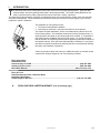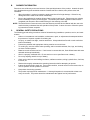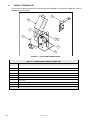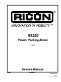
1
® R1250 Power Parking Brake PRINT Service Manual 03/25/02 32DPPB02.A 92-2002 RICON Corporation All Rights Reserved Printed in the United States of America This Ricon service manual is for use by qualified service technicians, and is not intended for use by nonprofessionals (do-it-yourselfers). The manual provides essential instructions and reference information, which supports qualified technicians in the correct installation and maintenance of Ricon products. Qualified service technicians have the training and knowledge to perform maintenance work properly and safely. For the location of a Ricon authorized service technician in your area, call Ricon Product Support at 1-800-322-2884. Customer Name: Installing Dealer: Date Installed: Serial Number: 32DPPB02.A i Revision Record ii REV DATE 32DPPB02 .A 03/25/02 PAGES DESCRIPTION OF CHANGE All Initial Release. ECR/ECO /4901 32DPPB02.A TABLE OF CONTENTS Chapter: I. INTRODUCTION ............................................................................................................................. 1-1 A. B. C. D. II. Page RICON ONE-YEAR LIMITED WARRANTY ................................................................................................... 1-1 SHIPMENT INFORMATION ........................................................................................................................... 1-3 GENERAL SAFETY PRECAUTIONS............................................................................................................. 1-3 PRODUCT TERMINOLOGY .......................................................................................................................... 1-4 INSTALLATION .............................................................................................................................. 2-1 A. B. C. D. E. F. G. REQUIRED TOOLS ........................................................................................................................................ 2-1 PREPARATION OF POWER PARKING BRAKE ........................................................................................... 2-1 VEHICLE PREPARATION .............................................................................................................................. 2-1 MECHANICAL INSTALLATION...................................................................................................................... 2-2 ELECTRICAL INSTALLATION ....................................................................................................................... 2-4 INSTALLATION VERIFICATION .................................................................................................................... 2-5 CUSTOMER ORIENTATION .......................................................................................................................... 2-5 III. MAINTENANCE AND TROUBLESHOOTING ................................................................................ 3-1 A. MAINTENANCE SCHEDULE ......................................................................................................................... 3-1 B. TROUBLESHOOTING GUIDE ....................................................................................................................... 3-1 IV. PARTS DIAGRAMS AND LISTS .................................................................................................... 4-1 32DPPB02.A iii This page intentionally left blank. iv 32DPPB02.A I. INTRODUCTION T he RICON R1250 Power Parking Brake adds hand-control to foot-operated parking brakes. Using the dash mounted switch, the factory parking brake pedal is electrically actuated. The Power Parking Brake does not need to interface with any other equipment and can be used with a variety of products. This manual provides information necessary for authorized Ricon service technicians to install, repair, and maintain the Power Parking Brake. Please follow these instructions exactly and call Ricon Product support if you have any problems or require assistance. The installation is a two-phase process: 1. The Power Parking Brake installation. 2. Instructing the customer in the proper and safe use of the product. This manual contains installation, service and maintenance instructions for the Power Parking Brake. The installation instructions must be followed exactly, no steps should be eliminated nor should the product be modified. It is important to user safety that the installation is thorough and correct. It is equally important that the operator be completely familiar with the Operating Instructions chapter of the operator manual. Once the Power Parking Brake is installed, it is very important that it be properly maintained by following the Ricon recommended cleaning, lubrication, and inspection instructions. If there are questions about this manual, or additional copies are needed, please contact Ricon Product Support at one of the following locations: Ricon Corporation 7900 Nelson Road Panorama City, CA 91402 .......................................................................................................... (818) 267-3000 Outside (818) Area Code ............................................................................................................ (800) 322-2884 World Wide Website ..........................................................................................................www.riconcorp.com Ricon U.K. Ltd. Littlemoss Business Park, Littlemoss Road Droylsden, Manchester United Kingdom, M43 7EF .................................................................................................. (+44) 161 301 6000 A. RICON ONE-YEAR LIMITED WARRANTY (refer to following page) 32DPPB02.A 1-1 RICON CORPORATION ONE-YEAR LIMITED WARRANTY Ricon Corporation (Ricon) warrants to the original purchaser of this product that Ricon will repair or replace at its option any parts that fail by reason of defective material or workmanship as follows: • Repair or replace parts for a period of one year from date of purchase. A complete list of parts covered by this warranty can be obtained from an authorized Ricon dealer. If You Need to Return a Product: Return this Ricon product to the installing dealer. Please give as much advance notice as possible and allow a reasonable amount of time for repairs. If You are Traveling: All authorized Ricon dealers honor this warranty. Consult telephone directory or call our Product Support department for the name of the nearest authorized Ricon dealer. This Warranty does not Cover: C Labor or service charges (these may be covered separately by the installing dealer). C Malfunction or damage to product parts caused by accident, misuse, lack of proper maintenance, neglect, improper adjustment, modification, alteration, the mechanical condition of vehicle, road hazards, overloading, failure to follow operating instructions, or acts of Nature (i.e., weather, lightning, flood). Note: Ricon recommends that this product be inspected by an authorized Ricon service technician at least once every six months or sooner if necessary. Any required maintenance should be performed at that time. This Warranty is Void if: WARNING! THIS PRODUCT HAS BEEN DESIGNED AND MANUFACTURED TO EXACT SPECIFICATIONS. MODIFICATION OF THIS PRODUCT IN ANY RESPECT CAN BE DANGEROUS • • The product has been installed or maintained by someone other than an authorized Ricon service technician. The product has been modified or altered in any respect from its original design without written authorization by Ricon. Ricon disclaims liability for any personal injury or property damage that results from operation of a Ricon product that has been modified from the original Ricon design. No person or company is authorized to change the design of this Ricon product without written authorization by Ricon. Ricon's obligation under this warranty is exclusively limited to the repair or exchange of parts that fail within the applicable warranty period. Ricon assumes no responsibility for expenses or damages, including incidental or consequential damages. Some states do not allow the exclusion or limitation of incidental or consequential damages, so the above limitation or exclusion may not apply. Important: The warranty registration card must be completed and returned to Ricon within 20 days after installation of this Ricon product for the warranty to be valid. The warranty is not transferable. The warranty gives specific legal rights, and there may be other rights that vary from state to state. 1-2 32DPPB02.A B. SHIPMENT INFORMATION Ricon does not sell directly to the user because of the specialized nature of the product. Instead, the product is distributed through the worldwide network of authorized Ricon dealers, who perform sales and installation. § When the product is received, unpack the product and check for freight damage. Claims for any damage should be made to the carrier immediately. § Be sure the installation kit contains all items listed on the kit packing list. Please report any missing items immediately to Ricon Product Support. The warranty and owner registration cards must be completed and returned to Ricon within 20 days for the warranty to be valid. NOTE: The Sales/Service Personnel must review the Warranty and this Service Manual with the user to be certain that they understand the safe operation of the product. Instruct the user to follow the operating instructions without exception. C. GENERAL SAFETY PRECAUTIONS The following general safety precautions must be followed during installation, operation, service, and maintenance: § § § § § § § § § § § § Under no circumstances can installation, maintenance, repair, or adjustments be attempted without the presence of a person capable of rendering aid. An injury, no matter how slight, must be attended to. Always administer first aid or seek medical attention immediately. Protective eyeshields and appropriate clothing must be worn at all times. To avoid injury, exercise caution when operating, and be certain that hands, feet, legs, and clothing are clear of brake operator. Batteries contain acid that can burn. If acid comes in contact with skin, flush affected area with water and wash with soap immediately. Work in a properly ventilated area. Do not smoke or use an open flame near a battery. Do not lay anything metallic on top of battery. Check under vehicle to avoid drilling into frame, subframe members, wiring, hydraulic lines, fuel lines, fuel tank, etc. Read and thoroughly understand the operating instructions before attempting to operate. Inspect the product before each use. If an unsafe condition, unusual noises or movements exist, do not use operator until the problem is corrected. Keep others clear during operation. The product requires periodic maintenance. A thorough inspection is recommended at least once every six months. The product should be maintained at the highest level of performance. 32DPPB02.A 1-3 D. PRODUCT TERMINOLOGY The references used throughout this manual are illustrated in Figure 1-1 and defined in Table 1-1. Refer to Chapter IV for more details. 9 8 7 6 1 2 5 3 4 FIGURE 1-1: R1250 POWER PARKING BRAKE TABLE 1-1: POWER PARKING BRAKE TERMINOLOGY REF DESCRIPTION 1 Hex screw 2 Split lock washer 3 Bronze bushing 4 Mounting bracket 5 Spindle 6 Control switch 7 Set screw 8 Motor assembly 9 Limit switch and bracket END OF TABLE 1-4 32DPPB02.A II. INSTALLATION T his chapter provides instructions for installing the RICON R1250 Power Parking Brake. The Power Parking Brake must be installed by an authorized Ricon service technician. Make sure that these instructions are read and understood before proceeding. Be certain that the installation instructions are followed exactly and do not eliminate any steps or modify the product. Perform the procedures carefully and in the order that they are presented. If any questions arise that are not covered in this chapter, contact Ricon Product Support for assistance. A. REQUIRED TOOLS C-clamp or locking pliers 3/64", 1/4", 5/32", & 1/2" drill bits Electric drill Round file Hammer with plastic tip Screwdrivers (Phillips and flat) Side cutter pliers Socket set Wire crimping tool Wrenches, open-end B. PREPARATION OF POWER PARKING BRAKE Remove Power Parking Brake and all accessories from packaging. Notify Ricon immediately if any part listed in the packing list is missing. Notify shipper if any part has been damaged in shipment. C. VEHICLE PREPARATION § § § Safely park vehicle on a flat, level surface and turn off engine. Be certain the transmission is set to PARK and the wheels are blocked. The Power Parking Brake must be mounted directly to the metal floor of the vehicle. Clear vehicle floor area of all loose material. Remove carpet, floor mats, molding, wall panels, or any other material that may interfere with the installation. 32DPPB02.A 2-1 D. MECHANICAL INSTALLATION To install the Power Parking Brake, follow this procedure: 1. Refer to Figure 2-3. If necessary, drill a 1/4" hole in the parking brake lever, just behind the pedal. This hole will be used to attach the wire cable. Refer to Figures 2-1 thru 2-3. Position the Power Parking Brake assembly under the parking brake lever as close as possible to the vehicle firewall and side panel. If possible, mount with the motor against the vehicle side panel. Be certain to align the Power Parking Brake spindle under the hole drilled in the parking brake lever. 2. LIMIT SWITCH WITH ROLLER LIMIT SWITCH WITH ROLLER MOTOR ASSEMBLY MOTOR ASSEMBLY WIRE ROPE WIRE ROPE FIGURE 2-1: FRONT VIEW OF LEFT-SIDE POWER PARKING BRAKE FIGURE 2-2: FRONT VIEW OF RIGHT-SIDE POWER PARKING BRAKE LIMIT SWITCH BRACKET LIMIT SWITCH WITH ROLLER HEX NUT MACHINE SCREW BRAKE LEVER WIRE HOLE OVAL SLEEVE MOTOR ASSEMBLY WIRE ROPE FIGURE 2-3: SIDE VIEW OF RIGHT-INSTALLED POWER PARKING BRAKE 3. Mark the three mounting holes and remove the Power Parking Brake. CAUTION! Check vehicle before drilling. Do not drill into factory wiring, hydraulic lines, fuel lines, fuel tank, etc. 4. 2-2 At the marked mounting hole locations, drill three 3/64" holes through the vehicle floor. 32DPPB02.A 5. Refer to Figure 2-4. Fasten the Power Parking Brake. Use the three hex bolts, washers, and hex nuts supplied. Be certain the bolts do not extend past the nuts into the wheel well. Remove the ends MOTOR ASSEMBLY HEX BOLT WASHER NUT FIGURE 2-4: VEHICLE FLOOR MOUNTING of the bolts, if necessary. 6. Refer to Figure 2-5. Using the two machine screws and hex nuts provided, attach the limit switch (with roller) to limit switch bracket. 7. The limit switch bracket is mounted on the underside of the vehicle dash (control holes panel). Position the bracket so the limit switch is activated when the parking brake is released (or not set). Drill two .164" (5/32) holes and use two of the #8 sheet metal screws to attach the switch bracket. Refer to Figure 2-6. Be certain the parking brake lever is in the released position and place the Power Parking Brake clamp on the parking brake handle. Secure the clamp to the parking brake handle and tighten. 8. 9. LIMIT SWITCH BRACKET CLAMP LIMIT SWITCH WITH ROLLER FIGURE 2-6: PARKING BRAKE CLAMP PHIL PAN ATTACHMENT MACHINE SCREW NYLON INSERT HEX NUT 32DPPB02.A 2-3 10. 11. 12. 13. 2-4 Place the oval sleeve around one end of the wire cable. Thread the wire cable through the hole in the parking brake. Tighten the oval sleeve. Loosen the set screw on the spindle and feed the other end of the wire cable through the spindle. Cut off excess wire and tighten the setscrew. Position the toggle switch in a location that is safe and convenient for the user. Drill a 1/2" hole. (Do not install the toggle switch at this time.) Reinstall vehicle carpet, floor mats, molding, wall panels, or other materials that were removed for the installation. 32DPPB02.A E. ELECTRICAL INSTALLATION TOGGLE SWITCH BOTTOM VIE W LIMIT SW ITCH 2 BLACK 3 1 SLIP ON TERM INAL YELL OW GREEN RED YELL OW 5 /1 6 R IN G CONN ECTOR # 10 BLUE RING CONNECTOR B AT A UX CIRCUIT BREAKER FIGURE 2-7: ELECTRICAL WIRING DIAGRAM 1. Crimp blue slip-on terminals to one end of the RED, BLACK, YELLOW, and GREEN wires. 2. Attach the slip-on terminals to the rear of the toggle switch as shown. 3. Permanently mount the toggle switch in its mounting hole. 4. Attach the other end of the BLACK wire to a good chassis ground. 5. Route the YELLOW wire from the toggle switch to the limit switch. Cut the wire to leave about 2" slack (save the excess wire) and crimp a blue ring-terminal to the end. Connect the terminal to the #2 terminal on the limit switch. 6. Cut a small section of the YELLOW excess wire and crimp slip-terminals to each end. Attach the terminals to the limit switch #1 and #2 terminals as shown. 7. Crimp a blue ring-terminal to one end of the excess YELLOW wire and attach the terminal to the #1 terminal on the limit switch. 8. Route the YELLOW wire from the limit switch to the motor. Cut the wire to leave about 2" slack and crimp a blue slip-on terminal to the wire. Connect the terminal to the motor terminal. 9. Route the GREEN wire from the toggle switch to the motor. Cut the wire to leave about 2" slack and crimp a blue slip-on terminal to the wire. Connect the terminal to the unused motor terminal. 10. Route the RED wire from the toggle switch through an existing hole in the firewall, and into the engine compartment. If possible, route the wire through an existing grommet. If not possible, drill a 3/8" diameter hole and use the snap-in grommet (provided). 11. At engine compartment, mount the supplied circuit breaker within 10 - 12 inches (25 - 30 cm) of battery. 12. Run the RED wire to the circuit breaker. Cut the wire to leave about 2" slack and crimp a blue ring terminal. Save the excess wire. Connect the ring terminal to the circuit breaker “AUX” terminal. 13. Crimp a blue ring terminal to the excess red wire. Connect the ring terminal to the “BAT” terminal on the circuit breaker. 14. Route the RED wire to the positive terminal of the vehicle battery. Cut the wire to leave about 2" slack, and crimp a large blue ring terminal to it. Connect the ring terminal to the positive terminal of the battery. Use the cable ties provided to secure all installed wires. 15. 32DPPB02.A 2-5 F. INSTALLATION VERIFICATION § § § G. Clear the vehicle floor of all loose material, high-plush carpet strands, etc. which may interfere with the operation of the power parking brake. Make sure that all fasteners are tightened properly. Run the Power Parking Brake through several cycles. CUSTOMER ORIENTATION IMPORTANT - Customer Orientation Ricon Sales/Service Personnel must review the Warranty and Operator Manual with the customer to be certain he/she understands the safe operation of the product. Instruct the customer to always follow the operating instructions without exception. 2-6 32DPPB02.A III. MAINTENANCE AND TROUBLESHOOTING R outine maintenance of the RICON R1250 Power Parking Brake will provide optimum performance. Regular maintenance will reduce the need for repairs. Since Ricon products are highly specialized, it is important that maintenance and repairs be performed by an authorized Ricon service technician using Ricon replacement parts. We recommend maintenance inspections at least every six months. A. MAINTENANCE SCHEDULE SIX MONTHS OF OPERATION Check for loose nuts and bolts. B. Tighten as needed. TROUBLESHOOTING GUIDE The troubleshooting guide is designed to provide a logical starting point to locate general problems that could occur with the power parking brake. However, not all possible problems or combinations of problems are listed. The guide does not incorporate routine safety precautions or preliminary procedures and assumes that the vehicle battery is fully charged and the battery terminals/connectors are clean and tight. WARNING! THE TROUBLESHOOTING GUIDE DOES NOT INCORPORATE ROUTINE SAFETY PRECAUTIONS OR PRELIMINARY PROCEDURES. ONLY AUTHORIZED RICON DEALERS SHOULD PERFORM TROUBLESHOOTING. TABLE 3-1: TROUBLESHOOTING GUIDE SYMPTOM POSSIBLE CAUSE Partial operation. Obstruction under Power Parking Brake. Remove obstruction and check for any damage Circuit breaker tripped. Reset circuit breaker. Limit switch stuck closed. Make sure limit switch releases normally. If problem continues, contact an authorized Ricon dealer for repair/replacement. II.E Loose wire terminal connection. Verify wire terminals are properly connected. II.E Control switch bad. Contact an authorized Ricon dealer for replacement NA No operation. Motor assembly bad. REMEDY REF. SEC. NA Operator Manual II.C.2 NA - No applicable section END OF TABLE 32DPPB02.A 3-1 This page intentionally left blank. 3-2 32DPPB02.A IV. PARTS DIAGRAMS AND LISTS T his chapter contains parts diagrams and lists for the RICON R1250 Power Parking Brake. The parts diagrams are exploded views of the components referenced by numbers. The accompanying parts list contains the part reference number, description, quantity used, and the Ricon stock number. For parts identification, locate the part on the appropriate drawing and note the reference number. The parts list that accompanies each drawing will list the stock number of the desired part. PRODUCT MODEL AND KIT NUMBERS PRODUCT NUMBER R1250 DOCUMENTATION KIT NUMBER 01047 DECAL SET NUMBER 26009 PARTS DIAGRAM ................................................................................................................................................... PAGE FIGURE 4-1: R1250 POWER BRAKE ......................................................................................................................... 4-2 32DPPB02.A 4-1 FIGURE 4-1: R1250 POWER BRAKE 4-2 32DPPB02.A POWER BRAKE MODEL R1250 SERIAL NO’S. 1001-PRESENT REF DESCRIPTION QTY 1 2 3 4 5 SETSCREW, HEX RECESS, 1/4 - 28 X 1/4 SPINDLE- W/HOLES BUSHING, BRONZE MTG BKT-WELD ASSY WASHER, 1/4 SPLIT LOCK 6 7 8 9 10 BOLT-HEX, 1/4-20 X 3/4 GR5 NUT-HEX, 6-32 NYLON INSERT BKT-LIMIT SWITCH, WELD ASSY SWITCH-LIMIT ROLLER LEVER MS 6-32 X 1 PHIL PAN 11 SWITCH-TOGGLE SPDT EXTRA LONG BAT: SERIAL NO’S 1001 TO 2370 SERIAL NO’S 2371 TO PRESENT STAR WASHER, TOGGLE SWITCH, U-109 NUT, U-550, TOGGLE SWITCH WIRE ROPE MOTOR-LEFT HAND DELCO: SERIAL NO’S 1001 TO 2370 SERIAL NO’S 2371 TO PRESENT DECAL, PATENT PENDING, GENERIC DIODE ASSY CIRCUIT BREAKER, 20A 12 13 14 15 16 * * PART NO. 2 1 1 1 3 3 2 1 1 2 28201 PB-1031 25315 PB-1010 28274 1 1 1 1 1 1 1 26430 26433 28346 28347 PB-1035 25408 V2-ES-040 1 1 1 32-10-171 R27-1003 26400 28166 28324 PB-1020 26452 28046 * Item not shown. 32DPPB02.A 4-3 This page intentionally left blank. 4-4 32DPPB02.A