1
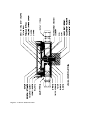
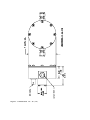
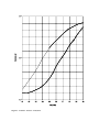
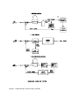
112800 REV.F
Maxtek Inc
Model MV-112
Piezoelectric Gas Leak Valve
Specifications
VALVE TYPE
CONTROLLABLE GASSES
FLOW RANGE
CLOSED LEAK RATE
RESPONSE TIME
MAXIMUM INLET PRESSURE
DRIVE REQUIREMENT
OPERATING TEMPERATURE RANGE
MATERIALS
INLET & OUTLET CONNECTIONS
PIEZOELECTRIC CRYSTAL
ANY COMPATIBLE WITH MATERIALS
0-500 SCCM
< 5 X 10⁻⁸ SCC/SEC (1 ATM HE ON INLET)
2 MILLISEC
50 PSI
0-100 VDC @ 10 µA or 0-24 VDC @ 15mA
+10°C TO +60°C
STAINLESS STEEL, VITON, TEFLON,
NICKEL PLATED CRYSTAL
7/16-20 O-RING PORTS PER SAE J514
¼” SWAGELOKTM *FITTINGS ARE
STANDARD
ELECTRICAL CONNECTOR
WEIGHT
¼” VCR CAJONTM **FITTINGS OPTIONAL
STANDARD BNC
800 GRAMS
* SWAGELOK IS A REGISTERED TRADEMARK OF THE SWAGELOK CO.
** CAJON IS A REGISTERED TRADEMARK OF THE CAJON CO.
Maxtek, Inc
http://www.maxtekinc.com
11980 Telegraph Road, Santa Fe Springs, CA 90670-6084
Tel: 562-906-1515 • FAX: 562-906-1622
Email: [email protected] • [email protected]
DESCRIPTION
HOUSING
COVER, HOUSING
VALVE SEAT
RETAINER, CRYSTAL
NUT, SEAT ADJUSTMENT
SPRING, PRELOAD XTAL
BALL, PRELOAD
CRYSTAL & SEAL ASSEM
FITTING, INLET (¼” SWAGELOKTM)
FITTING, INLET (OPTIONAL ¼” VCR CAJONTM)***
FITTING, OUTLET (¼” SWAGELOKTM)
FITTING, OUTLET (OPTIONAL ¼” VCR CAJONTM)***
CONNECTOR (BNC)
FILTER ELEMENT
SPRING, FILTER
SPRING, VALVE SEAT
O-RING - VALVE SEAT
O-RING - CRYSTAL
O-RING - COVER
O-RING - FILTER
O-RING - INLET & OUTLET
O-RING - BNC CONN
SCREW, CROSS REC. FILL HD 6-32 × 1/4
SCREW, CROSS REC. FILL HD 4-40 × 7/8
SCREW, CROSS REX. FILL HD 4-40 × 3/16
SCREW, CROSS REC. PAN HD #2-56 × 1/8
SCREW, CROSS REC. ROUND HD #0-80 × 1/4
WASHER, SPLIT LOCK - #2
WASHER, SPLIT LOCK - #4
WASHER, SPLIT LOCK - #6
MAXTEK
PART NO.
REQ'D
112409-1
112408
112401
112402
112403
112404
803111
112202
112411
112421
803112
803197
888007
803097
803099
803100
803102
803101
803103
803107
803105
803161
800070
800071
800072
800073
800074
800122
800128
800129
1
1
1
1
1
1
1
1
1
1
1
1
1
1
1
1
2
1
1
1
2
1
8
2
3
1
1
1
5
8
***USED ON MV-112 VALVE WITH VCR FITTINGS
Maxtek, Inc
http://www.maxtekinc.com
11980 Telegraph Road, Santa Fe Springs, CA 90670-6084
Tel: 562-906-1515 • FAX: 562-906-1622
Email: [email protected] • [email protected]
WARRANTY
Maxtek, Inc. guarantees the MV-112 Valve to be free of functional defects in material and workmanship
and will perform in accordance to the specifications published by Maxtek, Inc. in the appropriate
brochure for a period of one (1) year from the date of original shipment to purchaser. The foregoing
warranty is subject to the condition that the valve be properly installed and operated in accordance with
instructions provided by Maxtek, Inc. and has not been altered by anyone other than Maxtek, Inc. or has
not been subject to abuse, misuse, accident or damage during shipment.
Purchaser's sole and exclusive remedy under the above warranty is limited to, at Maxtek’s option, repair
or replacement of defective equipment or return to purchaser of the original purchase price.
Transportation charges must be prepaid and upon examination by Maxtek the equipment must be found
not to comply with the above warranty. In the event that Maxtek elects to refund the purchase price, the
equipment shall be the property of Maxtek.
This warranty is in lieu of all other warranties, expressed or implied and constitutes fulfillment of all of
Maxtek's liabilities to the purchaser. Maxtek does not warrant that the product can be used for any
particular purpose other than that covered by the applicable specifications. Maxtek assumes no liability
in any event, for consequential damages for anticipated or lost profits, incidental damage or loss of time
or other losses incurred by the purchaser or third party in connection with products covered by this
warranty or otherwise.
Repair and service beyond the warranty period will be provided by Maxtek, Inc. on a time and material
basis at current Maxtek, Inc. prices.
INSTALLATION AND MAINTENANCE
FEATURES
A piezoelectric valve has several features that are advantageous over other valves. They include no
mechanical linkage, no servomotor drives, no wear, no overshooting, fail-safe on loss of power with
automatic close, no leakage, external adjustment, minimum flow control and fast response (less than two
milliseconds).
For Example: Mass Flow Controller/Valves have a response time of 1 to 10 seconds which is 500 to
5,000 times as long as the MV-112 and Mass Flow Controllers/Valves have a 6 minimum flow rate of
about 1,000,000 times higher than the MV-112 minimum rate.
INSTALLATION
Installation of the MV-112 valve consists of plumbing the outlet port of the valve to a suitable port in the
vacuum system. The outlet port has a standard Swagelok™ ¼” tube fitting for this purpose. The gas
supply (Note: Inlet pressure must be regulated to 50-PSI max) is connected to the inlet fitting which is
also a Swagelok™ ¼” tube fitting which has been modified to retain the 7-micron inlet filter. Gas flow
direction is shown on the I.D. label on the valve housing.
OPERATION
The electrical input to the valve is via a standard BNC female connector. The control voltage is 0-100
VDC. Polarity must be positive to center contact and negative to the housing. Any 0-100 volt DC power
supply can be used for manual operation or an automatic pressure controller such as Veeco’s APC-100
can be used for closed loop operation.
ADJUSTMENTS
Normally no adjustments are necessary. The valve is adjusted at the factory for a threshold voltage
(voltage at which valve starts to open) of 20-30 volts. If this has decreased to the point where the valve is
not leak tight, it may be adjusted by removing warning label and turning the adjustment screw. NOTE:
The adjustment screw is very sensitive! Care must be used not to damage the crystal or valve seat.
NEVER turn adjusting screw more than 1/2 turn total. Evidence of damage caused by improper
adjustment or disassembly voids, the warranty. Turn screw in very small increments, (1) degree or less at
a time. Turning the screw clockwise increases the threshold voltage. Applying voltage to the valve until
a pressure change is noted in the vacuum system or leak detector makes adjustment. Note the voltage at
which this occurs and turn screw clockwise to increase voltage required to open valve and counter
clockwise to decrease voltage required.
MAINTENANCE
Normally no maintenance is required. If the filter becomes contaminated it is replaceable by removing
the inlet fitting (see valve construction drawing). If further maintenance is required return the valve to the
factory.
Figure 1 Temperature Effects on Throughput
Figure 2 Valve Construction
Figure 3 Dimensions in: cm (in)
Figure 4 Power versus Pressure
Figure 5 Generalized Closed Loop Systems
Figure 6 Input Voltage vs. Throughput
APPLICATION OF THE PIEZOELECTRIC VALVE MV-112
The MV-112 Piezoelectric Valve is suitable for applications requiring precision control of gas flow. The
following paragraphs outline the use of the valve in these applications including information relative to
installation and calibration.
OPERATION-GENERAL
The valve is tested and calibrated at the factory over an input voltage range of 0-100 VDC. This range
should not be exceeded in order to maintain factory checked parameters. The signal must be applied to
the center of the standard BNC male connector while the ground is connected to the outer body. Any 0100 VDC power supply can be used for manual operation or an automatic pressure controller can be used
for closed loop operation. Compatible controllers are:
CONTROLLER
VENDOR
APC-1000
80-1
DGC III
QUADREX PPC
250 B SERIES
VEECO
TYLAN GENERAL
PERKIN-ELMER
INFICON
MKS
OPEN LOOP OPERATION (MANUAL)
For successful open loop control, the parameter being controlled has to be visibly displayed so that the
control voltage (0-100 VDC) to the valve can be manually adjusted and the effects observed. In addition,
the system must be slow responding to manually compensate for changes in related parameter.
CLOSED LOOP OPERATION
The most common control system is of the closed loop type and is shown in general terms in Figure 5.
The sensor used in the system and fed back to the valve determines the type of system i.e. a pressure
sensor typifies a pressure control loop. Between the sensor and the valve, a controller is needed to
compare the sensor input with a setpoint and generate an error signal. The error signal is inverted and
amplified to increase the voltage to the valve when the sensor is less than the setpoint and decrease the
voltage to the valve when the sensor is more than the setpoint. The setpoint is usually a controller
adjustment.
The closed loop dynamic response is usually adjusted at the controller. The valve response time of 2
milliseconds or less is much faster than the typical system response making system functionally
insensitive to the valve response. This should be compared to the 6 to 10 seconds associated with mass
flow valves when picking your system configuration to assure a stable and accurate design.
As a system element, the valve is fail-safe in that it closed when power is removed, has low inertia for
minimum overshoot and no mechanical linkages for minimum wear and maximum reliability.
METHOD FOR DRIVING PIEZOELECTRICALLY ACTUATED VALVES
Piezoelectrically actuated valves are employed for controlling small flows of gases. A notable example is
the piezoelectrically actuated inlet valve, which is used for admitting gas to evacuated chambers at low,
controlled rates. Such valves have been operated either by (1) a D.C. voltage (fixed), the level of which is
adjusted to effect the desired opening, or by (2) duty cycle modulation (bang, bang). In duty cycle
modulation, the drive voltage is switched between two extreme values at which two voltages the valve is
fully closed and fully open respectively. Varying the proportion of time at the two voltage levels effects
control.
Both of these drive methods have shortcomings. (1) With the D.C. operation (a) accurate control is
difficult to achieve because of the hysteresis of the piezoelectric crystal and (b) when the valve opening is
small, a D.C. controlled valve is susceptible to clogging by contaminants. (2) With duty cycle
modulation, accurate control is readily achieved and there is a self-cleaning action, which reduces the
likelihood of clogging. However, valves which are driven by duty cycle modulation are often short-lived
because of the large, frequent voltage (and hence mechanical) excursions which are required for operation
when the valve is pre-loaded to ensure sealing in the absence of an applied voltage.
A drive method for such valves having significant advantages is the saw-tooth method where the voltage
applied to the piezoelectric crystal is relatively small amplitude triangular wave, which is superimposed
upon an adjustable D.C. level. Control is effected by adjustment of the D.C. level. Operation of a
piezoelectrically activated valve with this type of drive can be understood with reference to such a drive
signal with gradually increasing D.C. level applied to a pre-loaded valve. While the D.C. level is low, the
force generated in the crystal remains closed. At some point, as the D.C. level is increased, the force
generated at the peaks of the triangular waves becomes just sufficient to overcome the pre-load and open
the valve slightly for a very brief portion of each cycle. As the D.C. level increases further, both the
amount and duration of opening in each cycle increase with increasing D.C. level. If the valve was
controlled at this level the control would, in effect, be a combination of amplitude modulation and duty
cycle modulation. Still further increases in D.C. level increase the amount and duration of valve opening
in each cycle. However, the valve begins opening sufficiently far that further increases in the amount of
opening do not significantly change the flow through the valve. Control in this regime closely resembles
pure duty cycle modulation. Finally, at sufficiently high D.C. levels the valve goes beyond its control
range and is open all of the time (as in duty cycle modulation with a 100% duty cycle).
This drive method retains advantages of duty cycle modulation in that valve function is readily
controlled; and there is a self-cleaning action, which reduces the likelihood of valve clogging. Because
the dynamic voltage excursion is much less than in duty cycle modulation, however, the life of the
piezoelectric crystal and the valve seat are extended. In addition, the small dynamic excursion leads to a
quieter operation than with duty cycle modulation.
Experience with this method of control has also shown that stable control is more easily achieved than
with either duty cycle modulation or D.C. control.
PERFORMANCE PARAMETERS
The performance parameters of the valve are few in number and easy to interpret. The basic question is
what flow can be obtained at a known pressure drop over the temperature extremes of the application.
The valve has been characterized over the temperature range of plus 10° C to plus 60° C and a flow range
of 0-500 SCCM at 1 atm. The valve will function at higher flow rates and temperature ranges and
inquiries are welcome.
Figure 1is data showing the effects of different threshold adjustments and temperature variations on
performance. These performance curves must be considered when matching the valve to the system gain,
controller drive range, maximum throughput over temperature and control resolution.
Figure 4 provides data showing power applied versus pressure.
APPLICATIONS
Typically, the valve is used with a flow meter to control gas flow or an ion gauge to maintain a high
vacuum or installed in multiple lines as an on/off control in a gas mixing application. The lift of
applications includes but is not limited to the following:
1.
2.
3.
4.
5.
6.
7.
8.
9.
10.
11.
12.
Sputtering/Sputter Etching
Plasma Etching
Ion/Reactive Ion Milling
Diffusion Furnaces
Reactive Evaporation
Pressure Calibration Systems
Reactive Sputtering
Ion Beam Etching
Tube Backfilling
Ion Profiler
Mass Spectrometer
Tokamak Fusion Reactor
A piezoelectric valve has been modified and tested for pulsed operation and the data reported in industry
journals.
MATERIALS
The following is a list of materials used in the MV-112 compared to Veeco’s™ PV-10 valve, with
properties of material reflected.
PART
MAXTEK MV-112
MATERIAL
Bottom Cover
Crystal Retainer
Retainer Screw & Washer
Bottom Cover Screw
Fittings (2)
Fittings O-Rings (2)
Filter Spring
Filter O-Ring
Filter Element
Adjuster o-Ring
Wire Insulation
Preload Ball
Preload Spring
Spring Screw & Washer
Spacer O-Ring
Bottom Cover O-Ring
Main Housing
Piezo Element
Bimorph Bonding
Conductive Plating
Valve Seal Disk
Valve Seat/Adjuster
Adjuster Spring
Adjuster Housing
Adjuster Screw
Connector O-Ring
304 SS
304 SS
316 SS
316 SS
316 SS
Viton
400 SS
Viton
316 SS
Viton
Teflon
Teflon
400 SS
316 SS
Viton
Viton
304 SS
Ceramic
Epoxy
Nickel
Viton
304 SS
400 SS
304 SS
316 SS
Viton
M - Slightly Magnetic MM - Very Magnetic
NOTES
M
M
M **
M
V - Poor High Vacuum Material ** Silver is Available
VEECO™
PART
MATERIAL
Bottom Body (Cup)
Body Gasket
Retainer Screw (2)
Retainer Spring
Preload Button
Crystal Support
Piezo Element
Conductive Plating
Bimorph Bonding
Valve Seal Disk
Wire Insulation
Preload Spring
Spring Screw (3)
Locator Mastic
Main Housing & Seat
Fittings (2)
Fitting O-Ring (2)
Feedthrough Connector
Connector O-Ring
304 SS
Viton
NP Brass
410 SS
Acrylic
304 SS
Ceramic
Silver
Epoxy
Viton
Teflon
Blue Steel
316 SS
Silastic
304 SS
316 SS
Viton
Teflon
Viton
M - Slightly Magnetic MM - Very Magnetic
PV-10
NOTES
M
M
V
MM, V
V
V - Poor High Vacuum Material ** Silver is Available
(Comparison of Piezoelectric Valve Materials)
COMPATIBILITY
Gases, such as Argon, that are dry and non-corrosive can be continuously exposed to the valve. Gases
such as Chlorine, Ammonia and Hydrogen Sulfide will have a deleterious effect on the crystal and seal
assembly in the valve. The valve has been used with radioactive tritium gas, with Viton seals replaced
with EDPM.
MAGNETIC compatibility is a function of the material used in the construction of the valve and the
effect of the magnetic property on the valve performance. The previous page lists the magnetically
sensitive materials.
RELIABILITY
Warranty returns have been 0.5% or less for all valves shipped to date. The usual turn around time for
returned valves is 48 hours. If the crystal needs replacement, the required burn-in and seating procedures
extends this to 10 days maximum.