1
t
SHIMANO NEXUS 3-SPEED HUB
SG-3R40
SERVICE MANUAL
vol.1
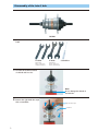
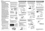
Disassembly of the Inter-3 hub
SG-3R40
Tools
1.
TL-HS20
TL-HS10
Hub spanners
Part no. Y-320 90010
15 mm/17 mm (2 pcs.)
Hub spanners
Part no. Y-230 90010
13 mm x 14 mm (2 pcs.)
Screwdriver
Hold the two bevelled surfaces
of the hub axle in a vice.
Note:
Do not damage the threads of
the hub axle.
2.
Remove the right hand dust cap A
with a screwdriver.
Right hand dust cap A
Screwdriver
2
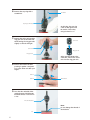
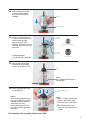
3.
Hold the two bevelled surfaces
of the hub axle on the driver
side in a vice.
Driver
Note:
Do not damage the threads of
the hub axle.
Vice
4.
Hold the left hand cone, and
then remove the lock nut for
left hand cone. Next, remove
the left hand cone.
TL-HS10
(14 mm)
Lock nut for left hand cone
TL-HS10
(14 mm)
Left hand cone
5.
Remove the hub shell.
Hub shell
Now it can be replaced with
the new internal assembly.
Internal assembly for quick
replacement
Part no.
Axle length
Y-33S 90700
Y-33S 98270
Y-33S 90710
170.3 mm
176.8 mm
189.4 mm
3
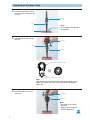
6.
Remove the stop ring with a
screwdriver.
Screwdriver
Stop ring (9.6 mm dia.)
At this time, the stop ring
come off with great force.
Be careful of the safety
using cloth and so on.
7.
Remove the carrier unit and the
ring gear unit at the same time
while turning the ring gear unit
slightly to the left and right.
Carrier unit
Carrier unit
Ring gear unit
Ring gear unit
After removing them at the
same time, remove the carrier
unit from the ring gear unit.
8.
Remove ball retainer K while
pressing in pawl A-1 and pawl
A-2 on the driver unit with your
fingers.
Pawl A-1
Pawl A-2
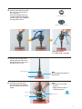
9.
Ball retainer K
Turn the axle unit with driver
upside down and hold the two
bevelled surfaces of the axle in
a vice.
Axle unit with driver
Note:
Do not damage the threads of
the hub axle.
Vice
4
10.
Remove the right hand lock
nut and the right hand cone
with dust seal from the hub
axle.
Right hand lock nut
TL-HS20
(17 mm)
TL-HS20
(15 mm)
Right hand cone with dust seal
11.
Remove ball retainer J from
the driver unit.
Ball retainer J
Driver unit
12.
Turn the driver unit clockwise
to remove it from the axle
unit.
Driver unit
Turn the driver
unit clockwise
Note:
Do not disassemble the axle unit,
otherwise it may cause problems
with gear shifting.
This completes the disassembly of the Inter-3 hub.
5
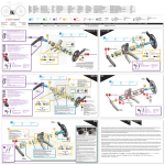
Assembly of the Inter-3 hub
1.
Hold the two bevelled surfaces
of the axle unit on the gear side
in a vice.
Axle unit
Gear
Note:
Do not damage the threads of
the hub axle.
Vice
2.
Install the driver unit onto the
axle unit.
Driver unit
Clutch
Axle unit
Smaller indents inside the driver unit
Smaller projections at top of clutch
Note:
Align the two smaller indents inside the driver unit with the two
smaller projections at the top of the clutch when installing the
driver unit.
3.
Place ball retainer J onto the
driver unit.
Ball retainer J
Driver unit
Note:
• Be careful of the setting
direction.
• Apply a liberal coating of
internal hub grease.
GREASE
(Y-041 20800)
6
4.
Screw the right hand cone with
dust seal onto the hub axle as
far as it will go.
Then turn the right hand cone
counterclockwise by 120 degree,
and then secure it by tightening
the right hand lock nut.
Right hand lock nut
Right hand cone with dust seal
120º
TL-HS20
(17 mm)
TL-HS20
(15 mm)
Tightening torque:
12 - 20 N·m {104 - 174 in.lbs}
5.
Turn the axle unit with driver
upside down and hold the two
bevelled surfaces of the axle on
the driver side in a vice.
Axle unit with driver
Note:
Do not damage the threads of
the hub axle.
Vice
6.
Install ball retainer K while
pressing in pawl A-1 and pawl
A-2 on the driver unit with your
fingers.
Note:
• Be careful of the setting
direction.
• Apply a liberal coating of
internal hub grease.
Pawl A-1
GREASE
Ball retainer K
(Y-041 20800)
Pawl A-2
7
7.
While pushing the two pawls B
on the ring gear unit with your
fingers, push the two pawls A-1
and the two pawls A-2 on the
driver unit one by one with a
screwdriver and install the ring
gear unit to the driver unit.
Ring gear unit
Pawl B
Internal ratchet
mechanism
Pawl A-1
Pawl A-2
Driver unit
OK
8.
Screwdriver
Note:
• Be careful of the directions of
the two pawls B.
• Apply a liberal coating of
internal hub grease.
• Check that pawls B are not
hooked onto the clutch.
• Check that pawls A-1 and A-2
are engaged with the ratchet
mechanism in the ring gear
unit.
• Apply a liberal coating of
internal hub grease to the gear
inside the ring gear unit.
Not OK
Engage the teeth of the
planetary gear of the carrier
unit with the teeth of the ring
gear unit while turning the
carrier unit slightly to the left
and right and pushing it onto
the ring gear unit.
Teeth of
carrier unit
planetary gear
Teeth of ring
gear unit
Note:
Apply a liberal coating of internal
hub grease to the planetary gear
(in 4 places) inside the carrier unit.
9.
Note:
After inserting the stop ring,
check that there is a small
amount of play in the carrier unit
in the vertical direction.
If there is no vertical play and the
carrier unit turns stiffly, turn the
internal assembly upside down
and hold the hub axle in a vice.
Then loosen the right hand lock
nut and the right hand cone with
dust seal to adjust until there is
sufficient play.
Insert the stop ring into the
groove of the hub axle.
Stop ring (9.6 mm dia.)
Groove of hub axle
8
Check:
Check that the stop ring
groove of the hub axle
is visible from the edge
of the carrier unit after
the carrier unit has
been installed.
Carrier unit
10.
While turning the hub shell
counterclockwise slightly,
place it onto the internal
assembly.
Hub shell
Internal assembly
11.
Screw on the left hand cone
to adjust so that the hub shell
can be turned smoothly
without any play. After
adjusting, secure the left hand
cone with the lock nut for left
hand cone.
TL-HS10
(14 mm)
Lock nut for left hand cone
TL-HS10
(14 mm)
Tightening torque:
12 - 20 N·m {104 - 174 in.lbs}
12.
Left hand cone
Turn the hub upside down
and hold the two bevelled
surfaces of the axle in a vice.
Driver
Note:
Do not damage the threads of
the hub axle.
Vice
13.
Install right hand dust cap A
to the hub shell.
Check:
After installing right hand dust
cap A to the hub shell, turn the
hub shell clockwise and check
that it turns smoothly.
If the hub shell does not turn
smoothly, re-install right hand
dust cap A.
Right hand dust cap A
Note:
• Apply a coating of internal hub
grease to the inside of right
hand dust cap A to waterproof
it.
• Push right hand dust cap A
firmly onto the hub shell until
it clicks.
This completes the assembly of the Inter-3 hub.
9
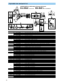
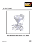
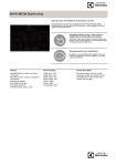
Exploded view and parts list
SHIMANO NEXUS 3-SPEED HUB w/Hi-Power Roller Brake
SG-3R40
16
18
M
12 13
14 15
IN
.2
N
Inter-M Brake
34
1
20 21 22 23
m
JA
PA
N
BR-IM31-R
24
Internal Assembly
Grease
25
04
For Axle Length
189.4 mm
Inter-3 Hub
PE-LD
17
GREAS
E
2
29
For Axle Length
170.3 mm / 176.8 mm
Bell Crank lll
26
11
27
19
For Axle Length
189.4 mm
13 12
30
28
1
SET
SET
31
2
3
4
5
6
7
8
9 10
For Axle Length
170.3 mm / 176.8 mm
11
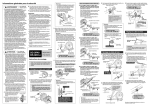
ITEM NO.
1
2
3
4
5
6
7
8
9
10
11
12
13
14
15
16
17
18
19
20
21
22
23
24
25
26
27
28
29
30
31
32
33
34
10
PART NO.
Y-33S 90700
Y-33S 98270
Y-33S 90710
Y-33Y 19000
Y-33S 90400
Y-33S 90300
Y-33R 90220
Y-33S 98040
Y-33S 98280
Y-33S 98050
Y-33S 90200
Y-33R 90210
Y-33R 90500
Y-33R 08100
Y-325 30100
Y-220 15010
Y-321 70020
Y-200 03000
Y-220 06000
Y-220 06040
Y-33Z 20200
Y-75V 13000
Y-75V 13010
Y-75V 16010
Y-75M 98050
Y-33F 98090
Y-75M 98060
Y-33F 98100
Y-75Y 98050
Y-75Y 98060
Y-31Z 06020
Y-33M 37000
Y-31Z 07000
Y-321 90220
Y-33R 05000
Y-33R 52001
Y-322 03200
Y-73T 21830
Y-73T 21930
Y-73T 22030
Y-73T 22130
Y-73T 22230
Y-73T 22330
Y-321 20010
Y-33R 98080
Y-33S 98180
Y-33S 98290
Y-33S 95100
Y-33S 98010
Y-33S 57000
Y-33S 98020
Y-33S 98030
Y-041 20800
Y-041 20400
DESCRIPTION
Internal Assembly (Axle Length 170.3 mm)
Internal Assembly (Axle Length 176.8 mm)
Internal Assembly (Axle Length 189.4 mm)
Stop Ring ( 9.6 mm)
Carrier Unit
Ring Gear Unit
Ball Retainer K (7/32" x 10)
Axle Unit (Axle Length 170.3 mm)
Axle Unit (Axle Length 176.8 mm)
Axle Unit (Axle Length 189.4 mm)
Driver Unit
Ball Retainer J (7/32" x 8)
Right Hand Cone w/Dust Seal
Right Hand Lock Nut (5 mm) for Axle Length 170.3 mm / 189.4 mm
Right Hand Lock Nut (9.9 mm) for Axle Length 176.8 mm
Flange Nut for Axle Length 170.3 mm / 176.8 mm
Hub Nut (7 mm) for Axle Length 189.4 mm
Hub Nut (9 mm) for Axle Length 189.4 mm
Washer (2 mm) for Axle Length 189.4 mm
Washer (3.2 mm) for Axle Length 189.4 mm
Non-turn Washer 2 (Yellow)
Brake Unit Fixing Nut (8.2 mm) for Axle Length 170.3 mm / 189.4 mm
Brake Unit Fixing Nut (9.7 mm) for Axle Length 176.8 mm
Grease Hole Cap
Brake Arm Clip Unit ( 15 mm)
Brake Arm Clip Unit (5/8")
Brake Arm Clip Unit (11/16")
Brake Arm Clip Unit (3/4")
Brake Cable Adjusting Bolt & Nut
Inner Cable Fixing Bolt & Nut
Lock Nut for Left Hand Cone
Left Hand Cone
Left Hand Dust Cap
Ball Retainer A (1/4" x 7)
Right Hand Dust Cap A
Right Hand Dust Cap B
Sprocket Wheel 16T (Black)
Sprocket Wheel 18T (Black)
Sprocket Wheel 19T (Black)
Sprocket Wheel 20T (Black)
Sprocket Wheel 21T (Black)
Sprocket Wheel 22T (Black)
Sprocket Wheel 23T (Black)
Snap Ring C
Push Rod (81.85 mm) for Axle Length 170.3 mm
Push Rod (86.85 mm) for Axle Length 176.8 mm
Push Rod (90.75 mm) for Axle Length 189.4 mm
Bell Crank Unit
Cable Adjusting Bolt & Nut
Bell Crank Body Fixing Bolt
Bell Crank Cover & Fixing Screw
Inner Cable Fixing Bolt Unit
Internal Hub Grease (Net. 100g)
Roller Brake Grease (Net. 100g)
32
33
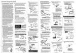
Inter-3 hub troubleshooting
Cause and remedy
Symptom
Mechanism spins
freely or slips
when in top 3
gear.
Malfunction of the internal
assembly. Replace with a new one.
Internal assembly
Malfunction of the axle unit and driver
unit. Replace with new ones.
Axle unit / Driver unit
Mechanism spins
freely or slips
when in normal
2 gear.
Malfunction of pawls B. Replace the
ring gear unit with a new one.
Ring gear unit
Malfunction of pawls A. Replace the
driver unit with a new one.
Mechanism spins
freely or slips
when in low 1
gear.
Driver unit
Malfunction of pawl D or the planetary gear.
Replace the carrier unit with a new one.
Carrier unit
Damaged ball retainer K (7/ 32" x 10), J (7/ 32" x 8) or A (1/4" x 7). Replace
the damaged part with a new one. Apply grease to the new part when
replacing.
Internal hub grease
Ball retainer
Turning is
difficult and
noise is heard.
K (7/ 32" x 10)
J (7/32" x 8)
A (1/4" x 7)
Part no. Y-041 20800
Incorrect installation of right hand dust cap A.
Install right hand dust cap correctly to the hub shell.
Right hand dust cap A
Malfunction of the bell crank unit.
Replace the bell crank unit with a new one.
Gear shifting is
not possible.
Bell crank
unit
Incorrect installation of the bell crank . Install the bell crank correctly.
Push rod does
not move.
Damaged or malfunctioning cable. Replace the cable with a new one of
a type recommended by Shimano.
Damaged or malfunctioning push rod.
Replace the push rod with a new one.
Push rod
11
SHIMANO AMERICAN CORPORATION
One Holland, Irvine, California 92618, U.S.A. Phone: +1-949-951-5003 Fax: +1-949-768-0920
Specifications are subject to change for improvement without notice.
This publication is printed on recycled paper.
MA33SA © Jan. 2004 Shimano Inc.
UCI official neutral
technical support
t