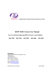
1
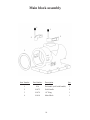
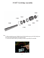
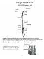
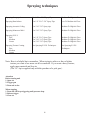
service Manual
Rotortex 230V/60HZ -240V50HZ
Edition 08/2008
19-230EU
19-245EU
Contents
Page
Safety requirement ..................................
3/4
General descriptions ................................
5
Operational instruction ............................
6/7
Main frame assembly ..............................
8
Main frame parts list ...............................
9
Main block assembly ...............................
10
Hopper and pump assembly ....................
11
Cartridge assembly ..................................
12
Trigger gun and short pole gun ...............
13
3’ and 5’ pole gun parts list .....................
14
Easy start-up tool ....................................
15
Spraying techniques ................................
16
Electrical component ...............................
17
Wiring diagram ........................................
18
CE Declaration of conformity .................
19
Rotortex warranty ....................................
20
SAFETY PRECAUTIONS
This manual contains information which must be read and understood before using
the equipment. When following instructions in the manual, pay close attention to
warnings following the symbol below.
SAFETY STANDARDS
The United States Government Safety Standards have been adopted under the Occupational
Safety and Health Act. These standards, particularly the General Standards, Part 1910 and
Construction Standards, Part 1926, should be consulted.
Warning and Precautions.
Never reach into sprayer jet with your finger or hands!
·
never aim the spray at yourself or other persons!
The material sprayer cause chemical burn or irritations!
Protect your skin and eyes!
The Rotortex sprayer designed to be operated is a dry environment, do not expose to rain,
mist or streams of water.
Warning!!! Never unplug main power cord during operation, it will damage the power drive!!!
Do not open power drive in any condition this will void your warrantee, in case of a problems
call Benron Equipment, Customer service at 888-327-9839 for direction assistant.
Do not use this product if ground terminal is damage or missing.
When using extension cord makes sure it accepts a grounding wire.
Do not attempt to operate this unit at other then 220v 60hz in the USA or 240v 50hz in Europe.
3
Do not attempt to change or short or cut the control cord from the gun switch to control box.
Do not operate this unit in an enclosed area that contains flammable materials.
Do not operate this unit within 30ft/10m of any flammable or explosive materials.
Do not operate the unit without the belt cover, keep your hand away it may result in
serious injury.
The Rotortex sprayer capable of high material pressure do not change hose fitting,
use original hose fittings and quick connectors.
When operate the sprayer make sure material hose in not kink, it make case for hose internal
tear or damage that will result in hose brake down and serious injury.
Check all connection for leaks.
The pump uses a connecting rod in the main pump block to turn the rotor. Keep all
foreign objects, hands, loose clothing or any other item form the main pump block.
Foreign objects, loose clothing or any other item may get caught in the rod and pull the
object into the main pump block.
Exercise extreme caution around the hopper.
Note the setting time of the material refer to manufacture instructions.
Safety Is First Priority!!!
4
GENERAL DESCRIPTION
Components
Cart with, pump, hopper, hose set, and cleaning kit.
Benron Texture Gun.(or pole gun)
Spray Tips, 1/8 in, 3/16 in., 1/4 in, and 5/16 in.
When pole select tip are, 3/16 in, 1/4 in, 5/16 in, 3/8 in, and 9/16 in use tip retainer.
50 ft , 1 in x 200psi Material Hose.
50 ft , 3/8 in x 200psi Air Hose.
51 ft Control Cord.
Specifications 19-230EU/19-245EU
Power Requirement...............................................230V, 60 Hz, and 240V, 50Hz
Spray Delivery with Texture Material................. 2GPM -7.7L/MI at 395/225 RPM
Hopper...................................................................17GAL- 65L
Pump Rotor Stator................................................2L3/1L4
Wash-Down Electric Motor……………………...2 HP - 1.55KW
Max. Pressure.........……………………………...450PSI -31BAR (with 2L3 set-up)
Aggregate size........................................................1/6” to 1/8” - 3mm to 4mm (2L3 set-up)
Run Amps @ Maximum load……………………7
Weight....................................................................170LB-77KG
Noise Lavel...........................................................74/85 at max speed and 1meter from sprayer
Dimensions
Width outer wheels ……………………….......24 in .- 61mm
Width outer hopper………....................................22 in. - 56mm
Length from front of pump to beck wheel...……..45 in. - 114mm ( 2L3 pump set up )
Height from floor to hendlle……………………..38 in. - 97mm
5
Operational instructions
Note: If you are a new user we recommend that you will operate the unit with water and dishwasher
detergent at first to get familiar with the sprayer operations.
1. Before starting the Rotortex make sure that the unit is properly assembled. You can do so by making sure
there are no missing parts and that every thing is connected in its place. (Follow instructions as indicated in
Owners Manual)
2. Inspect all electrical cords and connections; they must not be damaged in anyway. The grounding terminals
must not be missing. If any connectors look faulty do not use the unit until it has been replaced. It is imperative
that all connectors must be in perfect working condition.
3. Before connecting material hose to sprayer and gun, make sure the FWD/OFF/REV switch on the control
box is at off and the switch on the gun or pole gun is at off position. (The switch on the gun/pole gun must be
pushed down to be in off position)
4. Rinse material hose with a dishwasher soap and water to lubricate the hose. (This will help prevent any clogs
in your line)
5. Connect hoses to unit and the attached electrical cord to control box cord, make sure that the unit does not
start working; if it starts working shut it down immediately with e-stop!
6. Once your material has been prepared for spraying make sure that there are no foreign objects in the mix,
pour material into hopper. (Materials must be prepared to manufactures specifications)
7. Next find the Male Air Q/D on Front Right Side of the unit connect your air compressor into it and the Air
Hose that goes to the gun onto the other end. Remember to always Open the air valve at gun and allow air to
bleed out of the spray tip before you start the flow of the material. This will prevent the material from clogging
your needle and spray tip and beck flow in the air line.
8. Connect power cord to 230v or 240v only, and turn main switch to ON position.
9. Move FWD/OFF/REV switch on control box to FWD position. Sprayer should not turn on at this point.
Find the speed dial, we recommend that you start at half turn, you may increase to maximum speed if needed
by turning it to max. Now pull up the switch on the gun, at this point the sprayer should start. (Note the switch
on your gun/pole gun must be lifted or pulled up to turn on)
10. If sprayer does not start, push the switch on the gun/pole gun down and at control box switch to OFF
position.
6
11. The following instructions will indicate how to free the pump in case it is stuck or it has not been used long
enough for it to dry and it is now seized. Go to beck of sprayer find Belt-Guard insert ¾” tool provided through
the round hole at center and turn the shaft 5 to 8 turns clockwise only, this will allow material to flow in to
pump and free from be stuck, when you feel that it is free go back to step 6.
12. You must always mix materials before pouring into hopper. If any of the materials are not mixed properly
it may have dry clumps that can result in bad finishes.
13. Prime hose with the material by transferring it back to hopper, make sure material is not purging. Once
material is flowing through evenly adjust the speed dial to your desired setting.
14. It is always recommended that you try to spray on sample board before applying to final surface. Apply
material on to surface. (Note: when stopping for any reason you must push down switch on gun/pole gun to
stop the sprayer from delivering material. Failure to do so can build up pressure that can result in blown out
hose or severe bodily injury).
15. When finished, stop sprayer as instructed by step 14.
16. Mix dishwasher soap and water to clean out pump and hoses, if only water is available you must turn speed
dial to maximum speed, and clean hopper, pump and hoses. It is recommended that you should be as thorough
as possible when cleaning the sprayer. (Note: by doing so you will insure the sprayers longevity)
18. Before disconnecting the hoses you must turn FWD/OFF/REV switch on the control to REV pull switch
on gun/pole gun. This will work your pump in reverse resulting in the material being pulled back through the
pump and hose. (Note: do not go over 30 second on the reverse mode). Now you can proceed with disconnecting the hoses without they’re being any back pressure.
19. We highly recommended that after each use to disconnect the main pump from the main block assembly,
and wash with water the pump drive inside the main block.
20. If available use Permatex Silicone Spray Lubricant on the Rotor and Stator before assemble beck to main
block, make sure to place safety pin in holes after installations.
Note: Before starting the unit you must at first turn air on, trigger gun or open ball
Valve, and then turn on the sprayer on.
For stopping the sprayer you must before, to shut off On/Off switch, and keep spraying
until no material spray from the gun release trigger or close ball valve, and turn air off.
Fail to do that will result in clogged spray tip or hose from over pressure and material
being pack-up.
7
Main frame assembly
1
2
7
9
8
3
E
5
6
4
D
11
C
B
14
13
14
A
10
12
15
16
17
16
18
19
21
24
23
20
22
Note: Parts A, B, C, D, and E will change when the assembly build with 1L4 Rotor-Stator
8
11
Main frame parts list
Item Number
Part Number
Description
Qty
1
19-300
Control box assembly
1
2
19-028
Main frame
1
3
19-1558
Cartridge cover
1
4
19-1523
Guard for belt
1
5
19-1524
Guard cover
1
6
19-022EU
Belt
1
6A
19-084-225
Chain
1
7
19-025EU
Upper sprocket
1
7A
19-082
Upper gear
1
8
19-026EU
Lower sprocket
1
8A
19-081
Lower gear
1
9
19-027
Cartridge assy
1
10
15-282
Wheel
2
11
19-1578
Axle lock
4
12
19-308
Axle
2
13
19-309
Axle sleeve
2
14
19-060
Rubber foot
2
15
19-160
3/4 in Socket with handle
1
16
19-162
Spring grip
2
17
10-123
Air fitting
1
18
19-066
Air tube
1
19
16-012
Air quick connector
1
20
19-306
Control cable to main box
1
21
19-1541
Cable mounting plate
1
22
19-037EU
2HP electric motor
1
23
19-036
Main base support
1
24
19-307
Electric motor cable
1
Note: Parts 6, 6A, 7, 7A, 8, and 8A will change if low speed and more torque required.
9
Main block assembly
1
1
2
2
3
4
Item Number
Part Number
1
N/A
2
Description
Qty
Pin handle (sold with handle)
2
19-075
Side Handle
2
3
19-074
“O” Ring
1
4
19-010
Main Block
1
10
Hopper and pump assembly
1
3
2
4
5
Pump assy for pump P/n 19-245EU
1
19-1549
Special hose fitting
2
19-1543
Stator
3
19-1556
Stator fluid fitting
4
19-1542
Rotor
5
19-1531
Connecting rod
1
16
13
11
10
9
6-7-8
12
14
15
5
2
4
Item Number
Part Number
1
19-030-17
2
Description
3
Qty
Hopper
1
19-027
Cartridge Assy
1
3
19-010
Main Block Assy
1
4
19-301
Connecting Rod
1
5
19-302
2L3H Rotor
1
6
19-303
Redus Fitting
1
7
19-304
Nipple
1
8
19-1556
Stator Fluid Fitting
1
9
19-011/2L3
Stator
1
10
19-049
Special Hose Fitting
1
11
19-305
Screw and nut
2
12
19-018
Upper Fitting
1
13
19-016
2.5 in Clamp
2
14
19-048
Gasket Buna
1
15
19-019
Lower Fitting
1
16
19-017
“O” Ring
1
11
19-027 Cartridge assembly
Note:
A. When assemble insert part 19-006 in front of 19-004 and then press seal 19-002 with lip out.
B. Use heavy duty marine grease when repack bearing.
C. At the beck of shaft 19-009 is greas fitting, you must re-greas daily if use machine.
12
Trigger gun 16-311D and pole gun1 10-127/19 parts list
16
15
2
4
8
1
3
5
6
9
2
7
8
3
7
10
4
13
6
9
14
5
Note:
When using the gun to spray cement base products,
you must remove the needle after each job.
Clean and lube “O-ring on the needle item 7, and
needle adjustment item 9, with marine grease.
Needle removal direction:
Remove item 1, and 9, push needle from the tip side
through the back of the gun body.
Iten
Part #
Description
1
1
1
1
2
3
4
5
6
7
8
9
10
11
12
13
14
15
16
17
16-103
16-104
16-105
16-106
16-107
16-313
10-312
10-304
10-108
16-301
10-300
10-302
16-108
10-111
10-110
10-123
16-303
16-114
10-228
10-116
1/8” Round tip
3/16” Round tip
1/4” Round tip
5/16” Round tip
Tip retainer
Valve fitting
3/4” Ball valve
1” x 3/4” Fluid fitting
Trigger
Air needle
Fluid control nut guide
Fluid control
Gun body
Air vale regulator
Air valve
Air plug quick connect
Air adapter
Trigger pin
Needle fitting
O-ring not shown
11
10
12
11
13
12
14
15
19-163 removable
switch assembly
Quantity
1
1
1
1
1
1
1
1
1
1
1
1
1
1
1
1
1
1
1
4
Iten
1
1
1
1
2
3
4
5
6
7
8
9
10
11
12
13
14
15
13
Part #
Description
10-130A
10-130B
10-130C
10-130D
10-131
10-136
10-005
10-133
10-134
10-110
13-006A
10-139SW
19-065
13-095
13-091
10-153
10-140
10-146
3/16” Round tip
1/4” Round tip
5/16” Round tip
3/8” Round tip
Tip retainer
Gun body
Thumb screw
Stem
Bushing
Air valve
Quick connector
Switch body
Switch
1” Ball vale
Quick connector
Tube
Set screw
Air hose
Quantity
1
1
1
1
1
1
1
1
1
1
1
1
1
1
1
1
1
1
Pole gun 10-128/19 and
10-129/19 parts list
14
19-160 Easy start up tools
Note: Before starting up the sprayer you must insert tool 19-160 and turn clockwise
until pump turning free and easy. If necessary add water and soap to hopper.
Do not operate sprayer when handle is attached to shaft, must
remove handle and turn sprayer On.
Warning: If purchase sprayer 19-245EU do not turn handle counterclockwise, it will disconnect
the rotor from the connecting rod.
If disconnect remove P/N 19-1549 turn and push beck into connecting rod.
15
Spraying techniques
Spraying Orangepeel
Use 1/8” or 3/16”Spray Tips
Medium To High Air Flow.
Spraying Knockdown
Use 1/4”-5/16”-3/8” Spray Tips.
Low To Medium Air Flow.
Spraying Acoustic Ceiling
Use 5/16”-3/8” Spray tips.
Medium To High Air Flow.
Spraying Monocote Mk-6
Use 5/16”-3/8” Spray Tips.
Medium To High Air Flow.
Spraying E.I.F.S
Fine
Medium
Coarse
Use 1/8”-3/16” Spray Tips.
Use 3/16”-1/4” Spray Tips.
Use 5/16”-3/8” Spray Tips.
Medium To High Air Flow.
Medium To High Air Flow.
Medium To High Air Flow.
See Spraying E.I.F.S. Techniques.
See Spraying E.I.F.S.
Techniques.
Spraying Texture Coating.
Fine
Medium
Coarse
Note: Here is a helpful tip to remember. When trying to achieve a fine or lighter
texture you want to use more air & less material. If you want a heavy texture,
apply more material and less air.
(The 3/8” tip is supplied only with the purchase of a pole gun.)
Attention:
Before turning unit
1. Open air
2. Trigger gun
3. Turn unit to On.
When stopping
1. Turn unit Off keep triggering until pressure drop
2. Release trigger
3. Close air
16
Electric component
1 E-switch
5 Electric drive converter
2 Speed control
6 20 amps auto breaker
3 Green on light
7 Main switch body
4 Forward and revers control
8 Main E-switch body
1
3
2
4
Note: Item # 4 will work only forward when purchase sprayer P/n 19-245EU
7
5
8
17
6
Electric diagram
18
Van Nuys, California, U.S.A.
Eran Zagorsky
President
19
Rotortex warranty
All products manufactured by Benron Equipment & Supply, Inc. are warranted to the original purchaser against defects in
material and workmanship at the time of sale by an authorized Benron Equipment & Supply distributor and for a period of 12
months from date of purchase. This warranty applies only if the product is operated and maintained in accordance with Benron’s
written instructions.
Benron will repair or replace any part of the equipment proven defective. Repair or replacement under this warranty shall be the
purchaser’s sole remedy for breach of this warranty. Benron Equipment and Supply will not be responsible for any downtime
resulting from breakdown or for cost of rental equipment while repairs are being made.
This warranty does not cover damage to the product resulting from improper use, accident, user’s negligence, or if the product has
not been operated or installed in accordance with Benron’s recommendations. This warranty does not cover damages caused by
service or repair performed by other than a Benron authorized repair center. Benron is not liable for incidental or consequential
damages or to damages to other properties caused by use of the product in a faulty condition or manner.
Any implied warranty of merchantability or fitness for a particular purpose is limited to 90 days for professional rental use, and
for One year (12 months) for professional contractor use, from date of purchase. Some states do not allow limitations on how
long implied warranty lasts so above limitations may not apply to you.
If product is defective in material or workmanship during the warranty period, return it with proof of purchase to Benron
Equipment & Supply, Inc. or to Benron authorized warranty service center, for verification of claimed defect. If the alleged
defect is verified, Benron will repair or replace (at Benron’s option) any defective parts, and will return the product, transportation
prepaid. If no defects in material or workmanship are found, Benron will repair the product at a reasonable charge. Charges may
include the cost of parts, labor, and freight.
One year limited warranty, excluding consumable components.
The items, which are not covered, are:
Spry tips, Gun needle, Rotor and Stator, ball valves, Material hose, Air hose and control cords.
If gas or electric air compressor was purchased with sprayer it also has 1 year warranty.
This warranty does not cover damage or defects caused by or related to Abrasion, Corrosion, Abuse, Misuse, Negligence,
Accident, Normal wear, Faulty Installation or tampering in manner which impairs normal operation.
This warranty does not cover any burn of electrical components if proper electric cords or outlet has not been used.
15823 Stagg Street Van Nuys CA 91406
In USA Call: 1 (888) EASY-TEX (888 327-9839)
In California Call: (818) 787-4455
Fax:
(818) 787-8866
Web:
www.benron.com
E-mail:
[email protected]
20