1
Keyboard and Rack
PIN 93120013 01-A
Isnscnial@
THE TEcHNOLOGY THAT PERFoRMS
ENSONIQ Customer Service
Hours:
Monday through Friday
9:30 AM to 6:30 PM Eastern Time
Closed for lunch 12:15 PM to 1:15PM
Parts ordering in U.S. and Canada:
1-800-441-1003
NOTES:
EPS-J6 PLUS Service Manual
Table of Contents
TABLE OF CONTENTS
Page
Important Things to Know About the EPS-16 PLUS:
1. Getting Around the EPS-16 PLUS . . . . . . . . . . . . . .
2. Keyboard and Rack Similarities .. . . . . . . . . . . . . . .
3. The EPS-16 PLUS Keyboard Assembly and the Rack KPC Simulator
4. The Disk Drive . . . . . . . . . . . .
5. Operating System (O.S.) . . . . . . . .
6. Plastic Case (EPS-16 PLUS Keyboard only)
7. EPS-16 PLUS Rack Screws . . .
8. High Retention Force Connectors
Figure 1 - Scribe. . . . .
Communications Path . . . . . .
Figure 2 - Communications Path
1
1
1
2
3
3
4
4
4
5
5
Power Supply
Checking the Power Supply. ... . . . . .
Figure 3 - AC Line Voltage Check Points .
AC Line Voltage Measurements . . . . . .
Power Supply Measurements . . ... . . . .
Figure 4 - Power Supply Voltage Check Points
Transformer and Power Supply Voltage Check Points
Testing the Power Supply Unloaded . . . . . . . . . .
Figure 5 - Incorrect Power Supply Voltages (flow chart) .
7
7
7
8
8
8
9
9
Display
Display Self-test Mode. . .
Self-Test Chart. . . .' . .
10
10
Troubleshooting Guide. . . . . . . . .
11
12
13
14
15
Figure 6
Figure 7
Figure 8
Figure 9
-
-
Footswitch problem (flow chart)
No LEDs Lit (flow chart) . . .
Some LEOs Lit (flow chart) . . .
All LEDs Lit, No Display (flow chart)
Most Commonly Asked User Questions
16
EPS-16 PLUS Test Procedure:
1. Power Up . . . . . . . . .
2. Load in Sounds
............ .
3. Keyboard Test (EPS-16 PLUS Keyboard Only) .
4. Disk Check . . . . . • • . . . . . . . .
5 . Sound Check . . . . . . . . . . . . .
6. Mono Output and Headphone Test . . . . .
7. MIDI Test (EPS-16 PLUS Keyboard Only)
8. Footswitch Test . . . . . .
9. Analog Test Page . . . . . .
10. Sampling Test . . . . . . .
11. Output Expander (OEX-6) Test
12. ESP Effects Test 1 . . . . .
13. ESP Effects Test 2 . . . .
EPS-16 PLUS Burn-in Test Program
EPS-J6 PLUS Service Manual
17
17
17
17
18
18
18
18
19
19
19
20
20
21
Table of Contents-1
Tableo! Contents
EPS-16 PLUS Hardware Notes:
23
23
23
24
24
EPS-16 PLUS Keyboard and Rack . . . . . . . . .
Figure 10 - Trace cut for Rev A, B, or C Main Boards
Keyboard Only . . . . . . . . . . . .
Rack Only . . . . . . . . . . . . . . .
Figure 11 - Hardware Notes for the Rack .
Error Messages
. . . . . . . .'.
...
. .
25
Software Notes:
25
25
26
Checking the Software Version
Bootup ROM Changes . . . .
O.S. Disk Version 1.10 Changes
EPS-16 PLUS Keyboard Only Section
Figure 12
Section A
Section B
Figure 13
Section C
Figure 14
Section D
Section E
Section F
Section G
Section H
-
-
-
-
...
27
EPS-16 PLUS Keyboard. Exploded View
Replacing the EPS-16 PLUS Main Board . . . .
Replacing the EPS-16 PLUS Keypad/Display Board.
EPS-16 PLUS Button Colors . . . . . . . . .
Replacing the EPS-16 PLUS Keyboard . . . . .
Bottom of Case . . . . . . . . . . . . . .
Replacing the EPS-16 PLUS Power Supply Board.
Replacing the EPS-16 PLUS Transformer . . . . . .
Replacing the EPS-16 PLUS PitchIMod Wheel Assembly
Replacing the EPS-16 PLUS Line Filter .
Replacing the EPS-16 PLUS Disk Drive.
EPS-16 PLUS Rack Only Section . . . . . . .
Figure 16
Section A
Section B
Section C
Section D
Section E
Section F
Section G
Section H
Section J
-
-
-
-
-
28
29
29
30
30
31
31
32
32
33
33
35
36
37
EPS-16 PLUS Rack Exploded View . .
Replacing the Rack Main Board . . . .
Replacing the Rack Keypad/Display Board.
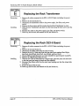
Replacing the Rack KPC Simulator Board.
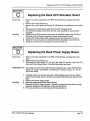
Replacing the Rack Power Supply Board
Replacing the Rack Transformer . . . .
Replacing the Rack OEX-6 Board . . .
Replacing the Rack Line Filter. . . . .
Replacing the Rack Disk Drive. . ... . .
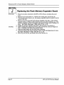
Replacing the Rack Memory Expander Board . .
38
39
39
40
40
41
41
42
Drawings
Figure 1 Figure 2 Figure 3 Figure 4 Figure 5 Figure 6 Figure 7 Figure 8 Figure 9 Figure 10 Figure 11 Figure 12Figure 13 Figure 14 Hgure 16 -
Scribe . . . • . . . . . . . .
Communications Path . . . . . . . . .
AC Line Voltage Check Points. . .
Power Supply Voltage Check Points . . .
Incorrect Power Supply Voltages (flow chart)
Footswitch problem (flow chart) . . . .
No LEOs Lit (flow chart) . . . . . . .
Some LEDs Lit (flow chart) . . . . . .
All LEDs Lit, No Display (flow chart) . .
Trace cut for Rev A, B, or C Main Boards
Hardware Notes for the Rack only.. . . .
EPS-16 PLUS Keyboard Exploded View
EPS-16 PLUS Button Colors . . . . . .
Bottom of Case . . . . . . . . . . .
EPS-16 PLUS Rack Exploded View . .
Table of Contents - 2
4
5
. .
7
8
.
.
9
12
13
14
15
. . . . .
. .
... .
23
24
28
30
31
36
EPS-16 PLUS Service Manual
Important
IMPORTANT THINGS TO KNOW ABOUT THE EPS-16 PLUS
IF YOU OONT READ ANY OTIIER PART OF TIllS MANUAL, READ TIllS SECTION.
As with every ENSONIQ product, all EPS-16 PLUS service will be handled through the ENSONIQ
Module Exchange Program. Rather than diagnose and exchange individual components, you will
replace complete mcxlules. We feel that this is the most time and cost effective method of repair,
both for you and your customers.
The instructions in this manual are for both the EPS-16 PLUS Keyboard and Rack
unless otherwise noted. Where the instructions say to check the keyboard of the EPS-16
PLUS, substitute a check of the KPC simulator board on the EPS-16 PLUS Rack.
When troubleshooting an EPS-16 PLUS, remove any optional modules that might be present. This
will prevent a faulty option from complicating your troubleshooting.
I. GETTING AROUND THE EPS-16 PLUS
You will need:
a. EPS-16 PLUS Operating System (O.S.) Disk
b. EPS-16 PLUS Test Disk (including test sounds)
c. Communications Test Board
d. EPS-16 PLUS Musician's Manual
2. KEYBOARD AND RACK SIMILARITIES
The Main Board and Power Supply board are the same for both the EPS-16 PLUS Keyboard and
Rack. However, there are physical differences that will require you to specify which unit you are
ordering parts for. The disk drive is the same for both units. The KeypadlDisplay boards are
different .
. .
Instead of:a Poly-Key Keyboard assembly (with KPC board), the Rack has a KPC simulator board.
The KPC simulator board. passes information between the KeypadIDisplay board and the Main
Board (like the KPC board does for the Keyboard unit). In the rest of this manual, whenever you
see "Keyboard assembly," substitute KPC simulator for the Rack (except where otherwise noted).
The operating system is only on the EPS-16 PLUS O.S. disk. This disk is the same for both the
EPS-16 PLUS Keyboard and Rack.
.
The EPS-16 PLUS Rack has the OEX-6 Output Expander and :ME-16 PLUS memory expander
built-in. These two expanders are options for the Keyboard unit. FLASHBANK (FB-l and FB-2
Kits) and SCSI (SP-2 Kit) are options for both.
3. THE IEPS-16 PLUS KEYBOARD ASSEMBLY
and the KPC SIMULATOR BOARD
The Poly-KeyTM Pressure Keyboard assembly on the EPS-16 PLUS (and the KPC siinulator board
on the RaCk) is a complex module that contains its own computer and software. So, when
necessary, you will be swapping it out as a whole unit Display information sent to and from the
Main Board is processed throQgh the Keyboard assemblylKPC simulator. What might appear to be
a frozen display, therefore, could be a bad Keyboard assemblylKPC simulator. For more
troubleshooting hints, see Communications Path on pp. 5-6 and flow charts on pp. 9, and 12-15.
EPS-J6 PLUS Service Manual
pagel
Important
IMPORT ANT! Keyboard assembly EPROM Version (EPS-16 PLUS Keyboard only)
Each version of the Keyboard assembly EPROM is optimized for the hardware that is within the
keyboard assembly. For more information about the Poly-Key Keyboard assembly, see ENSONIQ
Service Bulletins #9B and II.
The 2O-pin Ribbon Cable <Keyboard aSsembly/KPC Simulator)
When reconnecting this cable to the Main Board, make sure that the striped side is aligned with pin 1
and that the cable is not mis-pinned. If the cable ~ mis-pinned or installed backward, fuses F3 and
F4 on the power supply board will blow. NOTE: If one fuse blows, the other will also blow; you
must replace both.
When installing the keyboard assembly back into the EPS-16 PLUS, be sure that the keyboard
assembly cable is flat under the keyboard assembly and that the ferrite bead is not trapped on top of
the main board
.
4. THE DISK DRIVE
Transportinl: a unit
There is a printed label near the Disk Drive on every new unit shipped. This label contains important
information concerning the care of the EPS-16 PLUS Disk Drive and lists recommendations
regarding the treatment of the drive during transport. We do not, under any circumstances,
recommend the insertion of an actual disk during transport. Transport the unit only with
nothing in the drive at all.
PLEASE DO NOT SHIP AN EPS-16 PLUS OR A REPLACEMENT DISK DRIVE
IN A BOX PACKED WITH PEANUTS. If you must, wrap the entire unit in plastic first.
These peanuts may cause severe damage to the Disk Drive or Keyboard assembly.
What disks to use
It is very important to use double-sided, double-density 3.5" micro-floppy disks. The EPS-16
PLUS writes information to every track on a disk, so it is imperative that the disk be of superior
quality and certified for double-sided use.
Testini the Disk Drive
The best way to test the Disk Drive is by formatting a disk. When a disk is formatted, the EPS-16
PLUS reads and writes every track on that disk. If the formatting attempt fails, it is likely that the
disk itself is faulty. Always try formatting another blank disk before determining that the Disk Drive
is faulty. Unlike some computer systems, the EPS-16 PLUS does not automatically discard bad
sectors when formatting. The entire disk must be good for successful formatting.
. See Hardware Notes.- Rack Only for notes about the Panasonic Disk Drive.
page 2
EPS-J6 PLUS Service Manual
Important
5. OPERATING SYSTEM (O.S.)
An EPS-16 PLUS O.S. takes up approximately 170 blocks on a disk so without the O.S. on a disk
you have more room for sounds. The O.S. version on the disk can be easily updated (call
ENSONIQ Customer Service for the latest O.S. version). You cannot copy the O.S. to a disk onto
which you have already saved instruments or sequences, but not the O.S. Attempts to do so will
result in an error message.
To update O.S. Version on a floppy disk:
- Insert the disk containing the O.S. you want to copy (the source disk) into the floppy drive.
- Press Command, then System-MIDI, then 1 (Envl). The display shows COPY OS TO
DISK.
- Press Enter-Yes. The display says MUST ERASE MEMORY, OK? If you need to save any
sounds or sequences, press Cancel-No and save the data before proceeding.
- Press Enter-Yes. The display says READING OS INTO MEMORY, and then INSERT
FORMATTED DISK.
- Insert the disk onto which you want to copy the O.S. (the destination disk) into the floppy drive.
- .Press Enter-Yes. The display shows WRITING OS TO DISK while the O.S. is being copied
to the disk.
\Vhen it's done, the display reads COPY OS DONE. ANOlHER? If you want to copy the same
O.S. to another floppy disk, insert another formatted disk and press Enter-Yes. You can repeat
this procedure as many times as you like.
-
When you are done, press Cancel-No.
6. PLASTIC CASE (EPS-16 PLUS Keyboard only)
Avoid Strippin~ Screws
Because the structural components (Base, Control panel, and Wheel cover) are made of plastic,
great care should be exercised when assembling or disassembling any part of the EPS-16 PLUS.
Avoid over-tightening screws in the plastic case when executing any repair
procedure!
\Vhen replacing any of the self-tapping screws, it is possible to over-tighten the screws and strip a
hole in the case, making it necessary to replace the case or control panel. To keep this from
happening, follow these procedures:
a. Before replacing a self-tapping screw (or screws) into a stripped hole, put a drop or two of
LOCKTITE, Super Glue Gel, or RTV into the hole.
b. Install the screw, and tighten it only until the sub-assembly being attached is snug against the
case. Do not tighten the screw any further. When the glue sets, the screws will hold the
sub-assembly tightly in place.
It is important to make sure that there are no loose screws inside the unit, as they may come loose
and short out something.
Brass Inserts
To prevent stripping, there are brass inserts in the Main Board ground boss (mounting standoff) and
in the four control panel holes. Be sure to use machine screws in these locations. Do not use a
self-tapping screw in a brass insert as this will ruin the insert.
EPS-16 PLUS Service Manual
page 3
Important
7 . EPS-16 PLUS RACK SCREWS
Because the Control Panel is an aluminum extrusion, great care should be taken when assembling or
disassembling any part of it To avoid stripping and to aid in alignment, you should use no more
than 8 inchllbs of torque and try to install the screws into the existing holes in the panel.
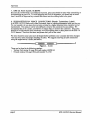
8. HIGH-RETENTION FORCE CONNECTORS (Repair Technicians Label)
In all EPS-16 PLUS Racks and in later Keyboards, there is warning{mformation label just for you.
We just wanted to let you know that we have switched to a higher retention force connector on our
transformers. This means it will be very difficult to remove this connector by just pulling. We
recommend the use of a scribe, screwdriver or similar object to remove this connector. Due to the
benefits of a high-retention force connector, we will be adding them in other places on the EPS-16
PLUS harness. Watch out for thein, and please don't pull on the wires!
We have found that some units have developed further problems once a module has been changed.
This may be a result of improper handling of cables. We suggest removing all cable connectors
using the angled end of a scribe (see below).
- -
Figure 1- Scribe
,
,
These can be found in the following catalogs:
• Techno-Tool catalog 38, page 204, part number 400PRI44
• Newark catalog lID, page 1024, part number 76-1510
page 4
EPS-J6 PLUS Service Manual
Communications Path
COMMUNICATIONS PATH
It is imponant that you completely understand the communications path of the EPS-J6 PLUS.
Please read this carefully.
The EPS-16 PLUS Main Board, KeypadlDisplay Board and Keyboard assembly are complete
computer systems in themselves, each with its own microprocessor and operating software. The
modules communicate with each other using serial communication ports. Whenever a key is played
on the Keyboard, for example, the Keyboard assembly microprocessor transmits this infonnation to
the microprocessor on the Main Board.
The KeypadlDisplay Board communicates with the Main Board through the Keyboard assembly.
Whenever the Main Board wants to put a message on the Display, it sends the message to the
Keyboard assembly which then passes it on to the Display. Whenever a button is pressed on the
control panel, the KeypadlDisplay Board sends the message to the Keyboard assembly which, in
turn, passes it on to the Main Board.
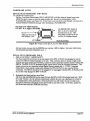
The communications path is shown in Figure 2. The Main Board communicates with the Keyboard
assembly over a two-line asynchronous interface carried by the 20-pin Keyboard assembly ribbon
cable. 'The Keyboard assembly communicates with the Keypad/Display Board over a three-line
synchronous interface which is carried over to the Main Board via the 20-pin ribbon cable, then up to
the Keypad/Display Board via the 7-pin Display cable on the EPS-16 PLUS and the 10-pinDispiay
cable on the EPS-16 PLUS Rack.
Due to the complexity of the modules involved, it is often difficult to detemrlne which module is at
fault when a communications problem occurs. To facilitate troubleshooting, a Communication Test
Board, Test Disk and Bum-in Test Disk are available.
DATA DATA CLOCK
KEYPAD/DISPLAY BOARD
IN
our our
J
,0
DATA DATA
MAIN BOARD
our
IN
2O-PIN RIBBON
CABLE
KEYBOARD!
, KPC SIMULATOR
,,
C
,
DATA DATA
our
()
4)
0115
(~ 112
,
\
DATA DATA
our
IN
ASYNCHRONOUS
FORT
7-PIN DISPLAY
CABLE
IN
CLOCK.
IN
SYNCHRONOUS PORT
~\..
~
Figure 2 -Communications Path
If a communication problem occurs (i.e., no display or no response to button presses or keys), it
could be something as simple as a ibad ribbon cable or Display cable, or it could be a problem in one
?f the modules. To help you identify a faulty module, a special Communication Test Board is
mcluded available from ENSONIQ Customer Service. The Communication Test Board simulates the
operation of the Keyboard assembly and can be used as a "known good" module in place of the
Keyboard assembly for troubleshooting.
EPS-J6 PLUS Service Manual
page 5
Communications Path
IMPORTANT!
When using the Communication Test Board, keep in mind that it is sensitive to static discharge.
Handle the board by the edges and store it in the anti-static shipping bag when not in use. Do not let
the board shan out when testing, place an insulator (cardboard, paper, etc.) underneath it.
Attaching the Communications Test Board
If an EPS-16 PLUS has a communications problem, turn the unit off and unplug the 20-pin
Keyboard assembly ribbon cable from the Main Board at -connector 112. Plug the 20-pin ribbon
cable from the Communication Test Board into 112. This will eliminate the Keyboard assembly as a
variable. Turn the system on. If the communications problem persists, you know the Keyboard
assembly is not at fault If communication is restarted, however, the Keyboard assembly is at fault.
See the flow charts on pp. 12-15 for troubleshooting procedures.
There is one funher complication. Since the communications path between the Keyboard assembly
and Keypad/Display Board is routed through the Main Board, there is a remote possibility that the
printed circuit connections between the two connectors are defective. If you have an EPS-16 PLUS
that has a problem communicating with its KeypadlDisplay Board, you may want to verify continuity
between the connectors on the Main Board Turn off the power and unplug the 2O-pin ribbon cable
from the EPS-16 PLUS Main Board at 112 and the EPS-16 PLUS 7-pin Display cable from the
Main Board atJl5. Using an Ohmmeter, verify continuity between the following points on the Main
Board:
20-pin Keyboard Connector
Pin 1
Pin 3
PinS
page 6
7-pin DisPlay Connector
to Pin 1
to Pin 2
to Pin 3
EPS-J6 PLUS Service Manual
EPS-J6 PLUS Power Circuitry
CHECKING THE POWER SUPPLY
Many EPS-16 PLUS problems may be related to a faulty Power Supply, Transformer or Line Filter.
You should check these before troubleshooting the rest of the unit.
Check to make sure that all the cable connections are secure and correct. Plug the EPS-16 PLUS in
and turn it on. Mter the EPS-16 PLUS has warmed up for five minutes, begin to test the voltages at
the points shown in Figures 3 and 4~ If the voltages vary outside the allowable limits, follow the
procedure described under TESTING TIlE POWER SUPPLY UNLOADED before replacing it
Line
Filter
Top
Lug
@
WARNING!
There are dangerous
Voltages present in
this area.
To Power ",nT""'"
NOTE: All wires
come from the bottom
of the transfonner.
Green
Figure3 AC Line Voltage Check Points
AC LINE VOLTAGE MEASUREMENTS (see Figure 3)
With the power switch OFF,
With the power switch ON,
the proper AC Line Voltage
the proper AC Line Voltage should read from:
should read from:
2B-IA, 2B-IB, 2B-3B, 2B-3A
2B-IA, 2B-2A, 2B-3B
There should be no voltage across the power switch.
EPS-J6 PLUS Service Manual
page 7
EPS-J6 PLUS Power Circuitry
POWER SUPPLY MEASUREMENTS
The voltage and part number of the Transfonner is denoted by the label on the top of the
Transformer. The Power Supply part number is silk-screened on the left side of the Power Supply
PC board.
J
I1.5 Amp,
F2
25 v
I FI ~
dAmp,25 V
F5
The Transformer part numbers for the EPS-16 PLUS are:
100V 1450000622
230V
1450000252
120V 1450000242
240V
1450000832
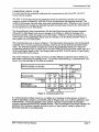
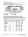
TRANSFORMER AND POWER SUPPLY VOLTAGE CHECK POINTS
The proper AC Line Voltage for each EPS-16 PLUS should be printed on the top of the
Transformer. Figure 3 shows the checkpoints for reading the AC Line Voltage. Figure 4 shows the
connector terminal numbers for the Power Supply and Transformer. It is normal for Line Voltage to
vary +/- 10%.
The following chart lists the voltage ranges for proper operation of each supply (fully loaded) and the
appropriate terminals to read across with the volt meter (refer to Figure 4 for terminal locations):
De~i&nali2n
I~rmiDals
CQDD~s:tQ[
AIIQ!fa.bI~ [aD&~
Digital Supply
Analog Supply
Display Fllament
+
1
4
7
3
6
9
J4
J4
J4
+VA
-VA
+5 Analog
+VDigital
+5 Memory
+5 Digital
10
12
14
15
16
18
11
11
13
13
13
17
J1
J1
J1
11
11
11
+20.00
-20.00
+4.75
+7.20
+4.75
+4.75
to +28.00
to -28.00
to +5.25
+5X
-35
FIlament
Display Offset
24
25
27
27
23
23
28
26
13
J3
J3
J3
+4.75
-29.00
4.70
-22.70
to +5.25
to -37.20
6.05
to
to -31.50
+.5X
19
20
J2
+4.75 to
page 8
13.00 to
22.00 to
4.70 to
to
to
to
18.70
28.60
6.05
+12.10
+5.25
+5.25
+5.25
Units
VACrms
VACnns
VACrms
VDC
VDC
VDC
VDC
VDC
VDC
VDC
VDC
VACnns
VDC
VDC
EPS-J6 PLUS Service Manual
EPS-J6 PLUS Power Circuitry
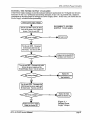
TESTING THE POWER SUPPLY UNLOADED
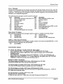
If the Power Supply readings exceed the indicated tolerance (particularly the +5 Digital line between
tenninals 18 and 17 or +5 Memory line between terminals 16 and 13) it is possible that a defective
component on the Main Board is drawing the Power Supply down. In this case, you should test the
Power SuppIy unloaded before proceeding.
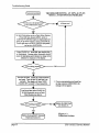
Incorrect power supply voltages
INCORRECT POWER
SUPPLY VOLT AGES
Tum the unit OFF Check the fuses.
Verify the the proper Line Voltage is
present Turn the unit ON.
===_---NO--....~~An better nowJ
YES
Tum the unit OFF. Disconnect
the Keyboard cable from the
main board. Turn the unit ON.
Keyboard/KPC)
... ( Replace the
NO ---IPl~ Simulator (see Section C).
.
YES
Turn the unit OFF. Disconnect the cable
between the power supply and the
Keypad/Display Board. Tmn the unit ON.
Replace the
==----NO
~ Keypad/DisplayBoard
(see Section B).
YES
Tmn the unit OFF. Disconnect the
cable between the power supply and
the main board. Tmn the unit ON.
Replace the Main
==---NO---1~ Board (see Section A).
YES
Figure 5 Replace the Power Supply
Board (see Section D).
EPS-J6 PLUS Service Manual
Incorrect Power
Supply Voltages
page 9
Display Self-Test Mode
DISPLAY SELF·TEST MODE
When the KeypadlDisplay is receiving power from the Power Supply but is not in proper
communication with the Main Board, the K.eypad/Display Board enters Self·test mode. In Selftest mode, the Display remains blank: until you press the buttons on the control panel. Pressing
various control panel buttons will cause the Display to print characters, home the cursor, etc.
Using Self·test Mode to Diagnose the Keypad/Display Assembly
1. If the unit comes in with a blank display, but is in Self·test mode (i.e., the Display
prints out characters when control panel buttons are pressed according to the chart below) this
indicates the problem is either the Main Board or the communication link between the Main
Board, Keyboard assembly and the KeypadlDisplay Board Before replacing anything, check all
connections, particularly the 20-pin cable to the Keyboard assembly.
If pressing buttons ca~ses only the leftmost character of the display to change, this usually
indicates a defective cable connection (20-pin ribbon cable) between the Main Board and
Keyboard assembly or possibly a bad Keyboard assembly.
2. If the unit is in Self·test mode but the display does not respond according to the
chart below, the problem is most likely in the KeypadlDisplay Board If certain buttons do
not function properly during normal EPS-16 PLUS operation, test them while the display is in
Self-test mode.
If you can't isolate a problem that seems related to the display, the display can be forced into Self-test
mode using the follOwing procedure. With the power off, face the front of the unit, then:
Jumper the left (-) side of C19 (located below the MIDI Out jack) to pin 13 of U20 (WD 1772). On
power up, the display will stay in Self-test as long as the jumper is connected, allowing you to check
the Keypad/Display Board independently.
The Chart below details how the control panel buttons are mapped in Self-test mode:
Eri:ss:
DiSula! Bi:ads:
LOAD
8
COMMAND
$
EDIT
1.
INS1RUMENT
SEQ-SONG
3
SYSTEM:-M1DI
9
EFFECTS
l/ENV 1
+
2/Er:..c"'V2
0
3/ENV3
1
4/PITCH
6
5lFILTER
7
61AMP
<
71LFO
8/WAVE
9/LAYER
O/I'RACK
UpArrow
=
(Home Cursor)
(Home Cursor)
pageJO
*
3.
Pri:SS:
DiSula! Ri:ads:
Down Arrow
4.
Left Arrow
.
Right Arrow
/
CANCEL-NO
?
(Home Cursor)
EIDER-YES
Instrument-Track 1
Space
Instrument-Track 2
&
Instrument-Track 3
,
Instrument-Track 4
2
Instrum.ent-Track 5
"
Instrument-Track 6
(Home Cursor)
Instrument-Track 7
5.
Instrument-Track 8
4
EFFEcr SELEcr-BYPASS 2.
SAMPLE
>
RECORD
STOP/CONTINUE
PLAY
o.
5
6.
EPS-J6 PLUS Service Manual
Troubleshooting Guide
TROUBLESHOOTING GUIDE
Often the faulty module in an EPS-16 PLUS can be determined through normal use. Sometimes, it
is difficult to isolate the problem. The following flowcharts can help you diagnose units that appear
dead (no display).
When troubleshooting an EPS-16 PLUS, always disconnect any expansion devices that may be
present (such as the memory expander, SCSI Interface or OEX~ Output Expander). This will
prevent a faulty expander from complicating your troubleshooting. The procedures for testing the
Memory Expander and the SCSI Interface are included with the corresponding expander. The
procedure for testing the OEX-6 can be found on p. 19.
The following pages include troubleshooting flow charts:
~Problem
9
12
Incorrect Power Supply Voltages
Footswitch problems
EPS-16 PLUS with No LEDs Lit
EPS-16 PLUS with Some LEDs Lit
EPS-16 PLUS with All LEDs Lit, No Display
13
14
15
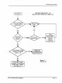
Troubleshooting an EPS-16 PLUS with a Footswitch Problem (see Figure 6)
If one or both of the footswitches do not operate properly, make sure that the footswitches are set to
the proper mode (on the Edit/System·MIDI page). See Section 2 of the EPS-16 PLUS Musician's
Manual) for more information.
.
The SUSTAIN Fr SWITCH parameter corresponds to the right pedal of SW-5 or single pedal
SW-l. The AUX FT SWITCH parameter corresponds to the left pedal of SW-5 only. The SW-5
is the Dual Footswitch (piano-type) available from ENSONIQ.
.
On the Edit/Ssystem·MIDI.page:
SUSTAIN FT SWITCH
SW-1 single footswitch, or
Footswitch
.
SW-5 right pedal
AUX FT SWITCH
SW-5 left pedal
Default
SUSTAIN
OFF
Option
right PATCH SL button
sequencer START/STOP
Option
-
left PATCH SEL button
If the footswitch mode is correct and the footswitch still doesn't function properly, there is either a
problem with the Main Board, the KeyboardIKPC or the 2O-pin ribbon cable connecting the two.
Although the footswitch jack is mounted on the Main Board, the footswitch signals are carried over
to. the KeyboardIKPC by the 2()-pin ribbon cable, where they are sensed by the KeyboardIKPC
mlcroprocessor.
EPS-16 PLUS Service Manual
page 11
Troubleshooting Guide
TROUBLESHOOTING AN EPS-16 PLUS
WITH A FOOTSWITCH PROBLEM
~-NO
YES
Set both footswitches to act as Patch Select Buttons.
Press Edit then System-MIDI, scroll to
SUSTAIN FI' SWITCH (right or single pedal) and
press the up arrow button to set it to PATCH SL.
Scroll right once to AUX Fr SWITCH (left pedal)
and set it to PATCH SEL.
Select PIANO 241. Press Edit, then double-click
on Instrument. Pressing either footswitch should
cause the appropriate patch indicator to change in the
·Iefunost two characters of the display.
~----YES---""
NO
Turn the unit OFF. Attach the communications
test board. Tum the unit ON and boot it up
nonnally. The display will show'" KBD
FAll...ED-TRY AGAIN? Press Cancel·No.
... If your communications test board has
an edge connector (4090013601) this
message will not appear.
Load in and then select PIANO 241.
Set both footswitch to act as Patch
Select Buttons (see above).
~--NO
Replace the Main Board
(see Section A).
YES
Replace Keyboard/KPC Simulator'
Board (see Section C).
page 12
Figure 6 Footswitch Problem
EPS-16 PLUS Service Manual
Troubleshooting Guide
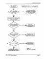
TROUBLESHOOTING AN
EPS-16 PLUS WITH NO LEDS LIT
NoLEDs lit.
NO
NO
YES
YES
YES
Check
KeyboardIKPC
20-pin ribbon
cable for
improper
connnection..
NO
YES·
Replace the
KeypadlDisplay
Board (Section B).
Figure 7 i Test the power supply
: unloaded. Go to Incmrect
Power Supply Voltages .
flow chan, p. 9.
E~S-16 PLUS S~ice
Manual
NoLEDsLit
page 13
Troubleshooting Guide
TROUBLESHOOTING AN EPS-16 PLUS
WITH SOME LEDS LIT
>--NO
Test the power supply
unloaded. Go to Incorrect
Power Supply Voltages
flow chart on p. 9.
YES
>-__ NO _ ........ Repaircable
JIll""
and retest.
YES
Place scope ground on the left
lead (negative) of C19 and probe
on pin 4 of J15-DISPLAY.
>--NO
Replace the Main Board
(see Section A).
YES
Replace the
KeypadlDisplay board
(see Section B).
page 14
Figure 8 Some LEDs Lit
EPS-16 PLUS Service ManZllll
Troubleshooting Guide
ALL LEDS LIT,
NO DISPLAY
TROUBLESHOOTING AN EPS-16 PLUS
WITH ALL LEDS LIT, NO DISPLAY
NO
:>---
Test the power supply
... unloaded. Go to Incorrect
--Ir.c Power Supply Voltages
flow chan, p. 9.
YES
Force the unit into self-test mode:
Jumper the negative (left) side of
C19 to pin 13 of U20.
...
Replace the
~-- NO --Ir- KeypadlDisplay Board
(see Section B).
YES
>-_ _ NO ___
Replace the Main
Board (see Section A).
YES
">---NO
.c
Repair and retest. )
YES
Replace the Keyboard/KPC
Simulator board (see Section C).
EPS-16 PLUS Service Manual
Figure 9 All LEDs Lit, No Display
page 15
User Questions
MOST COMMONLY ASKED USER QUESTIONS
The following questions are the most commonly asked by end users. Our Customer Service
Representatives (CSRs) resolve these situations over the telephone daily.
Question:
How do I Mix a Track or a Song?
CSR:
Sequences (Tracks)
1)
2)
3)
4)
5)
6)
7)
8)
Set RECORD MODE to ADD (see Section 8 o/the Musician's Manual)
Select the Instrument-Track
Press Edit then Track, scroll left to MIX
Set mix to the desired value
Hold Record and press Play
Let the Sequencer play one bar
Press Stop
Answer YES to KEEP=OLD - NEW
In Song Mode
1) Chain sequences into a Song
2)
3)
4)
5)
6)
Set RECORD MODE to ADD
Select the Instrument-Track
Press Edit then Track, scroll left to MIX
Hold Record and press Play
Mix Track through entire Song using the Data Entry Slider or the CV Pedal
with PED=VOL
7) Answer YES to KEEP=OLD - NEW
Question:
CSR:
Question:
CSR:
The EPS-16 PLUS will not record a sequence from external sequencer in MUL11
mode.
You must have O.S. version 1.1 or higher.
Why won't the EPS-16 PLUS let me edit converted Mirage sounds?
WS=1 contains the actual wavesample information for the Lower sound, WS=17
for the Upper. All other wave samples (30 of them) are copies of WS=1 or
WS=17. Therefore. isolate the desired wavesample(s) as follows:
1) Create a new Instrument (see Section 3 o/the MusiCian's Manu.al)
2) Create a new Layer in that Instrument (see Section 7 o/the Musician's
Manuol)
3) Copy desired wavesample into the new Layer (see Section 6o/the
Musician's Manual) .
4) Truncate the new wavesample (see Section 6 o/the Musician's Manual)
5) Edit as you wish
Question:
CSR:
pageJ6
Why do some other manufacturer's instruments crash when played from an
EPS-16 PLUS keyboard?
These instruments cannot handle the vast amount of MIDI data that Poly-Key
generates. Turn the key pressure settings to CHAN or OFF on MIDI and each
INSTRUMENT, as follows:
1) Press Edit, then System-MIDI (see Section 2 o/the Musician's Manual)
2) Scroll to BASECHANNEL PRESSURE=KEY
3) Change it to CHANNEL or OFF
4) Press Edit, then Instrument (see Section 3 o/the Musician's Manual)
5) Scroll to PRESSURE MODE=KEY
6) Change it to CHANNEL or OFF
EPS-J6 PLUS Service Manual
EPS-J6 PLUS Test Procedure
EPS-16 PLUS TEST PROCEDURE
The following procedure will ensure the thorough testing of the EPS-16 PLUS and also will aid in
troubleshooting the unit To do the following tests you will need a M1DI cable, a Dual Footswitch
(model SW-5), and a Control Voltage Pedal (model CVP-l). The EPS-16 PLUS should be
connected to a sound system in stereo.
If it is not known whether the KeypadlDisplay board is good, it can cause confusion in tracking
down the problem. If you do not have known-good correlation modules and suspect a
Keypad/Display problem, you should test this module fIrst (see Self-test Mode p. 10).
1. Power Up (see Section 1 of the EPS-J6 PLUS Musician's Manual for more information)
a. Tmn unit on. All the LEDs above the Instrument-Track buttons should light and the display
should read ENSONIQ EPS-16 PLUS, then PLEASE INSERT DISK.
b. Insen O.S. disk. The display should read LOADING SYSlEM. The EPS-l6 PLUS
(Keyboard unit only) will then display TUNING KBD - HANDS OFF. When the keyboard·
is tuned, all LEOs should go out.
2. Load in Sounds (see Section 1 of the EPS-16 PLUS Musician's Manual for more
information) .
a. Eject the O.S. disk. Insert the Test disk.
b. Load bank IN-OUT BURN from the test disk (press Load, Instrument, Ente,..Yes).
The display will say LOADING <filename> and the top yellow LED (redlorange on the
Rack) will blink while loading.
c. The file is done loading when the display shows FILE LOADED and the top yellow LED
(redlorange on the Rack) stays on. The following sounds will be loaded into the
Instruments-Trackl through 6:
Instrument 1
Instrument 2
Instrument 3
Instrument 4
Instrument 5
Instrument 6
PIANO 241
PRESSURE
6-0UTlEST
20 VOX lEST
SAMPLEINST
3 BUS TEST
3. Keyboard Test (EPS-16 PLUS Keyboard Only)
a. Select PRESSURE (lnstrument-Track2).
b. Playa chromatic scale across the entire keyboard. Press each key down only until normal
key travel ends. Do not press into pressure zone. Verify that no pressure effect occurs.
c. Press the key into the pressure zone and verify that pressure causes a pitch bend.
d. Using PRESSURE play all six "c" keys and verify that the pitch rises 1 octave smoothly
when the key is pressed down hard.
*
Failure indicates a Keyboard problem.
4. Disk Check
a. Select PRESSURE (lnstrument-Track2). Save PRESSURE back to the disk. Press
Command, and double-click on the Instrument button. The display shows SAVB
INSTRUMENT, press Enter-Yes.
b. The display will show NAME= PRESSURE. Press down arrow to change the name to
ORES SURE.
c. Press Ente,..Yes. The display will say DELElE OlD VERSION? (except the fIrst time
you save this sound). Press Ente,.. Yes to save ORESSURE (DISK COMMAND
COMPLETE will appear briefly when fInished).
d. Eject the test disk and then press Load. Verify that the display shows DISK DRIVE NOT
READY.
EPS-J6 PLUS Service Manual
page 17
EPS-16 PLUS Test Procedure
e. Reinsen the test disk and then press Load. Verify that the display shows FILE 1 IN-OUT
BURN.
f. Eject the test disk and then reinsert the test disk and press Load. A file name should appear
in the display. If the message DISK DRIVE NOT READY appears then FAn.. the unit.
g. REPEAT step f5times.
* If there is a failure, check the components in the following in order: 1) disk,
2) disk drive cables, 3) Disk Drive, and 4) Main Board.
S. Sound Check
a. Select PIANO 241 (Instrument-Track1). Playa bit to check sound quality. Play up the
keyboard to verify that PIANO 241 pans from left to right
b. Select 20 VOX JEST (Instrument-Track4). Press and hold down the three lowest white
keys. Twenty notes will play in succession with the last note dropping an octave. Verify
that there are no missing notes, distortion on a note, etc.
c. Select 3 BUS TEST (Instrument-Track 6). Press one key and you should hear 3 notes play
in succession.
* Failure indicates a main board problem.
6. Mono Output and Headphone Test
a. Select PIANO 241 (Instrument-Track1).
b. Unplug the LEFTIMONO output cable and verify that both the high and low end of the
keyboard are heard in the RIGHT output (there will be no output from the left).
c. Plug in the Left cable and unplug the RIGIIT/MONO output cable and verify that both the
high and low end of the keyboard are heard in the LEFT output (there will be no output from
the right).
d. Plug headphonesdlrect1.y into headphone jack.
e. Playa few notes to check for stereo and sound qUality.
f. Reconnect the audio cables.
* Failure indicates a Main Board problem.
7. MIDI Test (EPS-16 PLUS Keyboard Only)
a.
b.
c.
d.
e.
f.
Select PRESSURE (Instrument-Track2).
Connect MIDI In to MIDI Out with a MIDI cable.
Hold down a few keys.
Disconnect one end of the MIDI cable.
When you release the keys, the notes should sustain. .
Play twenty or more keys simultaneously to reinitialize the voices.
* Failure indicates a Main Board problem.
8. Footswitch Tests
a.
b.
c.
d.
*
Plug the Dual Footswitch into the Ft. Sw. jack on the back of the EPS-16 PLUS.
Press Edit, the System-MIDI and scroll to AUX FT SWITCH = OFF.
Press the up arrow button to change it to AUX FT SWITCH = START/STOP.
Create a shon sequence by holding down Record and pressing Play. Use the sustain
(right) pedal to verify that sustain works, then stop the sequencer using the sequencer (left)
pedal. Press Cancel-No.
If the footswitches do not operate correctly, see the Oowchart on p. 12.
page 18
EPS-J6 PLUS Service Manual
EPS-J6 PLUS Test Procedure
9. Analog Test Page
a. Plug Volume Pedal (model CVP-l) into the Pedal-CV jack.
b. Go to the Analog Test Page (press Command, Env 1, scroll right until EXAMINE
ANALOG INPUTS is displayed, then press Ente,..Yes).
c. Examine the analog inputs using the following procedure:
Press the Up Arrow button to select the appropriate input, then press Ente,.. Yes to take a
reading. Verify that the values are as follows:
Controller
1) PITCH WHEEL
2) MODWHEEL
3) VOL~(slideD
4) PEDAL (CV)
Down
o
o
o
o
lI12
127
127
127
127
Center
64
(Rack-always=O)
(Rack-always=O)
unplugged = 127
When testing the Data entry slider (Mr. Knob), you must scroll right so that the value is
underlined. Press Enter-Yes to take readings.
255
5) MR. KNOB (data slider) 0
*
. Scroll left then up to test the Patch Select Buttons.
6) PATCH (select buttons) both up=<> right=32
left=64
both=127
Failure indicates a problem with the corresponding part, although it also
could indicate a Power Supply failure or a Main Board problem. If all
readings are off, then it is most likely a problem with the Main Board.
10. Sampling Test
a. Plug the microphone into the Audio In.
b. Press Sample, the display shows LOAD OS DISK-mT EN1ER.
c. Eject the test disk and insert the O.S. disk and then press Ente,..Yes.
d. The display shows PICK SAMPLE INST. Press Instrument-TrackS, then Enter-Yes for
the VU meter.
e. Scroll right to INPUT LEVEL and set it to MIC, then scroll back to the VU meter..
f. Press Ente,.. Yes and sample by speaking into the microphone. You should hear what you
are sampling at the Audio Output.
g. Press Cancel-No to stop sampling. Play the sample and listen critically.
h. Press the Up Arrow button once and play the sample in BACKWARD, NO LOOP mode.
J. Unplug the microphone from the Audio In jack.
* Failure indicates a Main Board problem. For more information on Sa~pling,
see Section 5 of the EPS-16 PLUS Musician's Manual.
11.0EX-6
When troubleshooting an EPS-16 PLUS with an OEX--6 that is not operating properly, you will
need to determine whether the EPS-16 PLUS or the OEX--6 is at fault. Ifpossible. try the
OEX--6 with another EPS-16 PLUS. or try the problem EPS-16 PLUS with a different OEX-6.
The operation of the OEX--6 can be tested using the following procedure:
a. Load and select the sound called 6-0UT TEST.
b. While playing the same note on the keyboard. listen to each OEX-6 output individually. You
should hear a single square-wave tone in each output and the tone in each successive output
should be a semitone higher in pitch than the previous output.
Note that the OEX--6 outputs are not designed to drive headphones directly and should be
plugged into a suitable line-level pre-amp such as a mixing board.
* If the EPS-16 PLUS itself is defective, the problem is in the Main Board.
EPS-16 PLUS Service Manual
page 19
EPS-16 PLUS Test Procedure
12. ESP Effects Test 1
a. Eject the O.S. disk and insert the Test disk.
b. Press Load then Instrument. Scroll to the Bank file FILE 2 FX TEST 1 and press
Enter-Yes. Wait for all the instruments to load. The following sounds will be loaded into
the Instruments·Trackl through 8:
Instrument 1
Instrument 2
Instrument 3
Instrument 4
Instrument 5
Instrument 6
Instrument 7
Instrument 8
PIANO 241
ROOM REVERB
~REVERB
HIFIREVERB
DUAL DELAYS
HIFIDELAYS
PHASER+REVRB
CHORUS+REVRB
c. Select each instrument one at a time and play it Listen for ESP effects problems, sound
clarity, noise etc. Also watch for ESP download errors as an instrument is selected (either a
SYS1EM ERROR ### or the outputs playing dry instead of with effects).
* Failure indicates a Main Board problem.
13. ESP Effects Test 2
a. Press Load button then Instrument. Scroll to the Bank file FILE 3 FX TEST 2 and
press Enter-Yes. Wait for all the instruments to load. The following sounds will be
loaded into the Instrument·Trackl through 8:
Instrument 1
Instrument 2
Instrument 3
Instrument 4
Instrument 5
Instrument 6
Instrument 7
Instrument 8
PIANO 241
FLANGER+REV
CHOR+REV+DDL
ROT SPKR.+REV
CMP+DIST+REV
DIST+OIO+REV
WAH+DIST+REV
SPLASH1EST
b. Select each instrument one at a time and play it Listen for ESP effects problems, sound
clarity, noise etc. Also watch for ESP download errors as an instrument is selected.
Download errors will show up as either a SYSTEM ERROR ### or as the outputs playing
dry instead of with effects.
* Failure indicates .a Main Board problem.
page 20
EPS-J6 PLUS Service Manual
EPS-16 PLUS Burn-in Test Program
BURN·IN TEST PROGRAM
To run
-
the Bum-in Test Program, you must have the following items:
One EPS-16 PLUS Burn-in Test Disk
One MIDI Cable
One 1/4" Mono to 1/4" Mono cable
One 1/4" Stereo to 1/4" Stereo cable
The Bum-in Test Program is used at ENSONIQ to exercise the system hardware of a complete unit.
There are two test operations that the program can perform: 1) A continuous (bum-in) test of all
components, and 2) a keypad integrity test.
The continuous operations test the Dynamic RAM, Disk Drive Read and Write, MIDI InIOut,
Keyboard, Sustain Footswitch, Aux Footswitch. Disk Drive Index Pulse, ESP RAM, ESP GPR
Registers, and E.SP Instruction Registers. The Disk Drive Read and Write tests are run
approximately every ten minutes and take about five minutes to run. Failures of components can be
automatically detected in all operations.
BURN·IN TEST
1. Plug MIDI Loop Cable into MIDI In and MIDI Out jacks. Plug the Mono to Mono cable into
the Audio Out/Left and PedaZ-CV jacks. Plug the Stereo to Stereo cable into the Headphones
and Ft. Sw. jacks.
2. Power up the unit and insert the BURN-IN TEST DISK VER. X.x. making certain that the disk
is not write-protected (i.e., the window must be closed).
3. Once the disk has been loaded, the display will read: DISK TEST COUNT XXX. If no buttons
are pressed the Bum-in Test cycle will begin automatically after twenty seconds.
NOTE: The ''Disk Test Counter" is used to automatically monitor test disk usage and to indicate
when a test disk becomes· unreliable. The "counter"is increased by one every time a DISK WRITE
test is done. After about two weeks of continuous Bum-in Testing, the "counter" will reach its limit,
and the disk will not boot the system properly. Instead, the display will read: DISK NO LONGER
USABLE. Contact ENSONIQ Customer Service fora replacement disk.
4. Press Enter-Yes. The display will read: DO BUTTON TEST?
NOTE: If you wish. press Cancel-No to by-pass the Button and Display tests and immediately
begin the Bum-in Test cycle. The display will read: OK-HIT ENTER TO START. Go to Step 9 to
start the Bmo-in Test cycle.
S. Press Ente,.Yes. All the special segments on the left·side of the display will light and the
display will.read: LEFT SIDE ON-HIT ENTER.
6. Press Ente,.Yes. All the special segments on the right side of the display will light and the
display will read: RIGHT SIDE ON-HIT EN1ER.
7 • Press Enter-Yes. All the LEDs will light and the display will read: LEDS ALL ON-IDT
ENTER.
S. Press Enter-Yes. The display will read.: PRESS EVERY BU1TON. Press all the control
panel buttons in any order. All the LEDs will flash as each button is pressed (don't forget to
press the leight Instrument-Track buttons). Once all the buttons are pressed, the display will read:
OK-HIT ENTER TO START.
9. Press Ente,.Yes to start the Burn-in Test cycle. As the Bum-in Test runs, the display will
indicate which of the tests is cmrently active. If the Dynamic Ram is being tested, for example.
the display will read. TESTING DYNAMIC RAM.
EPS-16 PLUS Service Manual
page 21
EPS-J6 PLUS Burn-in Test Program
BURN-IN FAILURE MODES
1. If there is a failure in any of the tests, the special segments in the display and the control panel
LEDs will flash alternately. The test cycle will continue.
2. To determine which test has failed, press Cancel-No. When the test that is currently being
performed is finished the display will indicate a "PASS/FAIL STATUS" mode. If the Dynamic
Ram has passed, for example, the display will read DYNAMIC RAM GOOD.
3 . Pressing any of the arrow keys will cause the program to page through and display the pass/fail
status of each of the eleven tests. Once the failed test has been located, you can clear the pass/fail
status mode by pressing Cancel-No. This should be done ONLY as a diagnostic function.
Once all failure status indicators have been cleared, press Enter-Yes to restart the Bum-in Test
cycle at the displayed test
4. Pressing the Edit button will display the number of times the test has been performed and the
number of times the test has failed. The format is shown below:
Test Iterations
Test Failures
xxxxx
xxxxx
Failed Test
DYNAMIC RAM
DISK WRITE
DISK READ
N.lIDI IN/OUT
KEYBOARD
SUSTAIN FOOTSWITCH
AUX FOOTSWITCH
INDEX PULSE (Disk Drive)
ESP RAM
ESP GPR REGISTERS
ESP INSTR REGISTERS
page 22
(xxxxx = 5 digit count value)
Problem in order of likelihood
Main Board
Test Disk, Disk Drive cable, Disk Drive, Main Board
Test Disk, Disk Drive cable, Disk Drive, Main Board
Check cable continuity and cable insertion, Main Board
Keyboard cable, Keyboard
Check cable continuity and cable insertion, Main Board, Keyboard
Check cable continuity and cable insertion, Main Board, Keyboard
Disk Drive cable, Disk Drive, Main Board
Main Board
Main Board
Main Board
EPS-J6 PLUS Service Manual
Hardware Notes
HARDWARE NOTES
EPS-16 PLUS KEYBOARD AND RACK
FLASHBANK Format Errors
On Rev C and lower Main boards ONLY (4001013501 with Rev letter is located next to the
MIDI Thru jack) a trace cut must be made in order for the unit to work properly with a
FLASHBANK option (see Figure 10). If this trace is not cut all the way through, you may get a
FLASH FORMAT ERROR message when formatting a FLASHBANK.
DO NOT CUT THIS TRACE
ON REV D (or hi"gher) BOARDS
31
Pin 38
:>
make sure the trace to
this feedthru is cut.
CUT ...............'-Lo
81
On 40010013501 board of"
Rev A, B, or C, make sure
that this trace is cut. This
trace does not need to be cut
on Rev D or higher boards.
Main Board Edge
Figure 10 -Trace cut for Rev A, B, or C Main Boards
For best results, be sure that the EPROMs are version 1.ooF or higher. For more information,
see Keyboard and Rack Similarities on p. 1.
EPS-16 PLUS KEYBOARD ONLY
1. OEX-6CAUTION!!! Th1PORTANT!!!
The 8-pin mini-DIN connector on the rear panel of the EPS-16 PLUS should only be used to
connect the OEX-6 Output Expander to the unit. This connector does not simply supply audio
outputs and signal ground and, therefore, cannot be used to generate separate outputs without the"
OEX-6. The EPS-16 PLUS generates digital signals which must be convened externally. The
signals present on this connector include digital control signals and +/- 15VDC. Improper
connections to these signals could easily damage the EPS-16 PLUS or any external device
connected. The OEX-6 should never be plugged in or unplugged with the EPS-16 PLUS power
on, as this could damage the EPS-16 PLUS.
2. Keyboards that think that they are a Rack
The O.S. disk and EPROMs are the same for both the EPS-16 PLUS keyboard and rack. With
O.S. disk Version 1.00, the software determined whether the unit was a keyboard or a rack by
the value/position of the pitchwheel. If the pitchwheel was off center, the unit would not go
through the keyboard calibration routine and would act just like a rack. To fix this, update the
unit to the latest software (EPROMs and disk).
EPS-J6 PLUS Service Manual
page 23
Hardware Notes
EPS-16 PLUS RACK ONLY
1. Dim Displays or Extra Segments (SIN 10000 to 10244)
On early EPS-16 PLUS Racks, there is a potential for the Display to shon out to the front panel.
This can cause extra segments of the display to light or the whole display may appear dim. To
fIx this problem, remove the keypad/display board from the front panel. Place insulating tape
along the flat inside edge of the front panel (both top and bottom). Reinstall the KeypadlDisplay.
2. Panasonic m-257 Disk Drive
On early EPS-16 PLUS Racks that have a Panasonic JU-257 disk drive, there is a potential for a
short between the disk drive mounting bracket and the case of the disk drive that may cause audio
noise during a floppy disk access. There are two ways to fix this problem:
• Place insulatiDg tape on the sides of the drive to isolate the it from the mounting bracket, or
• Carefully remove (desolder) the surface-mounted resistor labeled RI30 from the disk drive
PCB. With the bezel closest to you (pCB side up), R130 is located on the right side of the
PCB next to the PCB mounting screw.
3. Main Board PEM (threaded mounting standoff)
On some early units, one main board screw was left out due to the misplacement of a Main Board
mounting PEM.H there is no screw in this location (see Figure 11), don't insert one.
cr-
SCSI board 5. When installing a REV A SCSI board
emory
into a Rack, be sure that the REV A
Expander.",
0
mark in this comer is disconnected
Board 0 0
0 -0
from the trace next to it.
M
o
0
0
4. Leave these two mounting
screws out when:
Figure 11 • it is a REV A Memory
o
Main Board
Hardware Notes
Expander board, and
for the Rack only
• no SCSI bom:l is installed.
o
o
0
3. If this Main Board hole doesn't line up with
its mounting PEM, leave the screw out.
4. ME-I6 PLUS Memory Expander Board
On some REV A boards, one of the mounting screws could connect a +5V trace to the grounded
chassis (see Figure 11). On power up, the unit would show LOADING SYS1EM but get no
further. Leave these two screws out when a REV A memory expander board is used and when
no SCSI board is installed (no screw head will touch the trace when a SCSI board is installed).
5. SCSI Board
On some REV A SCSI boards, a mounting screw could connect a +5V trace to the grounded
chassis (see Figure 11). Use a razor knife to disconnect the bottom left corner of the "R" in REV
A from. thettace next to it.
page 24
EPS-J6 PLUS Service Manual
Software Notes
Error Messages
Occasional error messages are not unusual, and unless they become chronic, they are not a cause for
concern. It is important to realize that these messages are diagnostics and do not necessarily indicate
a problem. These messages were designed to help our software engineers in the development of the
software, not as hardware diagnostics.
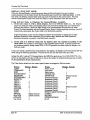
The following error messages could be caused by software:
ID ~
Description
ID #
16
poly or mono pressure events sent to VC 133
20
unknown button event
134
48
parameter error
135
49
layer error
137
80
bad buffer to MIDI
138
128
bus error
139
129
odd address error
192
130
divide by zero
193
131
illegal instruction
194
132
chk instruction register out of bounds
Description
trapv instruction overllow error
privilege violation
trace
line 1111 emulator
spurious interrupt
unused vector
load all data error (from :MIDI or card)
keyup playback error
out of SOBs error
Main Board Problems
The following unexpected event messages could be caused by a problem on the Main Board:
32
bad download
40
bad ESP error
33
bad ESP chip
138
spurious interrupt
34
bad ESP RAM
145
unknown OUART interrupt error
MIDI 'or Main Board Problems
The following unexpected event message is usually caused by too much incoming MIDI data. It also
could be caused by a problem with the keyboard:
144
out of buffers
SOFTWARE NOTES
To Check the Software Version from the front panel:
• Press Command, Envl. The display shows NO COMMANDS ON PAGE.
• Repeatedly press the left or right arrow button until·the display shows SOFfWARE
INFORMATION.
• Press Enter-Yes. The display shows RAM VERSION = X.XX, press Enter-Yes, the
display shows ROM VERSION = Y.YY, press Enter-Yes, the display shows KEYBOARD
VERSION = XXX (for the Rack, this will always read 1).
BOOTUP ROM CHANGES
The foHowing change was included in ROM Version l.00B (Keyboard only, SIN 10460):
Enended Ithe acceptable range of Mod wheel and other analog inputs.
The following change was included in ROM Version 1.00c (Keyboard only, SIN 11646):
This veaion ·ofROMsupports loading the operating system from FLASHBANK.
The following change was included in ROM Version l.00D (Keyboard SIN 12440):
This version of ROM fixes a problem when the FLASH memory is completely filled (0 blocks free). All EPS-16
PLUS Racks have at least this version.
The following change was included in ROM Version l.OOE:
(Keyboard SIN 12471. Rack SIN 10290)
A change was made to allow the CV pedal value on the Analog Test page go full range (0-127).
EPS-J6 PLUS Service Manual
page2S
Software Notes
The following change was included in ROM Version l.00F:
(Keyboard SIN 13871, Rack SIN 10738)
A bug was fixed that caused a DISK TYPE ERROR when saving instruments to FLASHBANK.
The following changes were included in O.S. DISK VERSION 1.10:
In version 1.10, the MULTI-TRACK RECORD feature, which was omitted from version 1.00. has been implemented.
In addition. there are two additional refmements added as ofv 1.10 to make the software a little more user-friendly:
• When you go into Record after loading or deleting instruments (a condition that requires the EPS-16 PLUS to
shuffle memory for a second or two) the display will show SHUFFLING DATA, until the click starts and it is ready
to record. Previously there was no visual feedback during this time, causing users to wonder what was going on;
• When the sequencer is synced to MIDI (CLOCK. SOURCE=MIDI on the EDIT/Seq·Song page) and you press record,
the display shows WAITING... to indicate that the unit is waiting for a MIDI Start and clocks before going into
Record.
If the sequencer is synced to MIDI and it needs to shuffle memory before going into record, it will show
SHUFFLING DATA for as long as necessary, then go to WAITING... Always wait until the display shows waiting
before starti:ng the sending device.
The following is a summary of changes which were included in version 1.10:
HANGING NOTES
• It was possible to make notes hang while playing DIST GUITAR sound (related to layer delay).
PITCH WHEEL
• Pitch wheel reading drifted as the unit warmed up.
MIDI
• If TRANSMIT ON=INST CHAN, it didn't send proper values for key pressure out MIDI.
• Sustain pedals from MIDI were not recorded properly by the sequencer.
LOADING AND SAVING
• When you loaded an Instrument into a copy of an already loaded instrument, it sometimes crashed, displaying
ERROR 129.
• The EPS-16 PLUS did not handle errors properly when saving multi-disk fIles, particularly when resaving an
existing one. Sometimes it created two Disk 1's and a Disk 2 for a 3-disk sound.
• When a bank should have been loading sounds from hard disk, the unit seemed to ask for a floppy. then displayed
WRONG DISK INSERTED when you inserted the floppy, because it was really looking at the hard disk but with
the wrong disk label.
• When an EPS (classic) bank was loaded. the track PAN values were ttanslated incorrectly in the presets.
SEQUENCER
• It was possible to edit track parameters when no Instrument was loaded.
• Click pan defaulted to +3; it should default to 0 (center).
• On CHORUS + REVERB algorithm, click assigned to BUS3 still came out left channel when BUS3=OFF.
• Click assigned to BUS3 periodically snuck into BUS1, creating a reverb splash, especially with 44KHZ effects.
• Overdub Standby state was not cleared when an 1Dllooped sequence stopped.
EFFECTS
• Effects could howl when loading a bank with a playback rate different from the existing one.
• On 44KHZ REVERB algorithm, Denme Rate and Amt parameters were interconnected, changing either one changed
.
the other.
SAMPLING
• Entering and exiting sampling while holding keys and sustain pedal could confuse the unit, causing sustain pedal to
hang. or be ignored. or worse.
page 26
EPS-J6 PLUS Service Ma1UJ1l1
EPS-16 PLUS KEYBOARD ONLY
EPS·16 PLUS KEYBOARD
ONLY SECTION
Contents:
Figure 12 16 PLUS Keyboard ExPloded View
Replacing Modules
A - Main Board . . . . . . .
B - Keypad/Display Board. . .
Figure 13 EPS-16 PLUS Button Colors
C - Keyboard. . . . .
Figure 14 Bottom ojCase . . . . .
D - Power Supply Board . . .
E - Transformer. . . . . . .
F - Pitch/Mod Wheel Assembly .
G - Line Filter. . . . . . . .
H - DiskDrive . . . . . . .
EPS-16 PLUS Service Manual
page
28
29
29
30
30
31
31
32
32
33
33
fl,lge 27
f
t
-_-7---,SliderKnObS
I
I
I
I
1~==-_
\
---- ---------..~
I
..
i
-~
~--~
I
~
~
--=-~
)
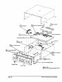
Power Supply
Board
Figure 12 EPS-16 PLUS Keyboard Exploded View
page 28
EPS-J6 PLUS Service Manual
Replacing EPS-16 PLUS Modules (KEYBOARD ONLY)
Replacing the Main Board
Removing
Installing
1. Remove all cables connected to the EPS-16 PLUS, including the Power cord.
2. Remove the four (4) screws that fasten the control panel with a 2.5mm hex
wrench and raise the control panel. NOTE: These are machine screws.
3. Remove the Keyboard (see Section C). Note that you should remove the 20-pin
ribbon cable from the Main Board (at J12) instead of from the Keyboard.
4. Disconnect all cables from the Main Board:
a. Push-on ground wire (located between the :MIDI Thru and MIDI Out jacks)
b. J4-DISK, 34-pin ribbon cable
.
c. HI-POWER, 9-wire cable
d. J13-WHEELS,
e. J15-DISPLAY,
f. J2-NON-VOLATTI...E :MEMORY and/or J3-AUXEXPANSION (if present)
5. Remove the six (6) 15mm nuts from the rear panel jacks marked Ft. Sw.,
PedaleCV, Left/Mono, Right/Mono, Audio In and Phones.
6. Remove the eight (8) self-tapping screws and one ground machine screw with
star washer that attach the Main Board to the case and remove the board
7. With the board tilted on a slight angle, insert the jacks into the holes in the rear
panel. Press the board down and into place.
8. Replace the Main Board screws and secure the jacks with the nuts.
9. Reconnect the cables. Reinstall the Keyboard (see Section C).
10. Power up, test the unit, and close the control panel.
SECTION
B
Removing
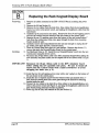
Replacing the Keypad/Display Board
1. Remove all cables connected to the EPS-16 PLUS, Including the Power cord.
2. Remove the Volume and the Data Entry knobs. Remove the four (4) screws that
fasten the control panel with a 2.5mm hex wrench and raise the panel NOTE:
These are machine .screws.
3. Remove the six-wire cable from the left side and seven-wire cable from the right
side of the Keypad/Display board. Note that these cables are keyed.
IMPORT ANT! The individual colored buttons are held in place only by the Keypad/Display
board underlay. Make sure the control panel is open all the way to prevent the
buttons from falling out when the board is removed If they do fall out, see
Figure 13 for button color placement.
4.. Remove the fomteen (14) screws that hold the KeypadlDisplay in place and
Installing
carefully remove the Keypad/Display. Remove the cardboard insulator that
covers the bottom of the Keypad/Display board.
5. To reassemble, first make sure that the underlay and all the buttons are in place
and that the lens is clean and in its proper position.
6. Install the new KeypadlDisplay board with the cardboard insulator using the
fourteen (14) screws. Reconnect the two cables paying particular attention to the
polarity. Reinstall the knobs on the Data Entry and Volume sliders.
7. Power up, test the unit, and close the control panel.
EPS-16 PLUS Service Manual
page 29
Replacing EPS-J6 PLUS Modules (KEYBOARD ONLY)
....
-- ••• ---- ..
-1
2
3
4
5
6
7
8
II
A
Etn.ment
Load
ling
Command
IBlack I
IBlack I
1
IBlack I
~
~
v
. .MIDI . . . . .
Volume
=
No
0
Edit
III
Mode==Page
Cancel
Data
Y/iIS
EnIer
Continue
Entry====== =;;;E~~ue~ncer=
. Figure 13 -EPS-16 PLUS Button Colors
I
Dark Grey]
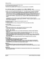
Replacing the Keyboard
Removing
Installing
1. Remove all cables connected to the EPS-16 PLUS, including the Power cord.
2. Remove the four (4) screws that secure the control panel with a 2.5mm hex
wrench. NOTE: These are machine screws.
3. Place the unit upside down on a soft surface and remove the ten (10) screws that
attach the Keyboard to the·case. See Figure 14 for location of screws.
4. Carefully turn the unit right side up. Raise the control panel and disconnect the
Keyboard Ribbon cable (12) from the Main Board, paying particular attention to
the polarity.
5. Remove the Keyboard from the case by gently lifting up the front of it while
pulling it toward the front of the unit Once the rear of the Keyboard has cleared
the control panel mounting tabs, the Keyboard can be removed from the
Keyboard cavity (see pp. 1-2.).
.
6. While paying particular attention to polarity, remove the Keyboard Ribbon cable
from the old Keyboard and install it on the new Keyboard.
7. Connect the Keyboard Ribbon cable to the Main Board. Be sure that the cable
lies flat beneath the Keyboard and is not pinched under the Keyboard frame.
IMPORT ANT! If the ribbon cable is mispinned, fuses F3 and F4 on the power supply will blow.
8. Insert the new Keyboard rear first into the unit at the front of the Keyboard
cavity. Gently slide the Keyboard toward the rear of the unit, lowering the front
of the Keyboard as needed to clear the control panel mounting tabs.
IMPORT ANT! Make sure the Disk Drive ribbon cable is not caught under the Keyboard
standoffs.
9. Turn the unit upside down on a soft surface and replace the ten (10) screws that
secure the Keyboard to the case.
10. Power up, test the unit, and close the control panel.
page 30
EPS-J6 PLUS Service Manual
Replacing EPS-J6 PLUS Modules (KEYBOARD ONLY)
• Front of Case (Keyboard Side) •
0)
0
0
• •
0
•
0
•
0
•
o
•
~(g
Keyboard
Screws
•
o
o
~D
• •
•
•
Wheel
Assembl
Screws
0
0
0
I
•
•
•
(c)
1111111 U 11111
I
Figure 14 -Bottom of Case
SECTION
D
Removing
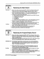
Replacing the Power Supply Board
1. Remove all cables connected to the EPS-16 PLUS, including the Power cord.
2. Remove the four (4) screws that fasten the control panel with a 2.5mm hex
wrench. NOTE: These are machine screws.
3. Disconnect the 9-pin connectors (II, J4), the 6-pin connector (13), and the 4-pin
connector (J2) from the Power Supply Board. Note that these connectors are
keyed.
IMPORT ANT! The connector on the 9-pin cable from the transformer has a high retention force.
Please use a scribe, screwdriver, or similar tool to remove it (see p. 4). Do not
pull on the wires!
Installing
4. Remove the screw and star washer that connect the ground wire to the heatsink.
5. Remove the two (2) screws and nuts that secure the Power Supply to the case
(note that there are star washers on each screw).
6 .. Remove the Power Supply board by pulling the front of the board toward the
Keyboard and then lifting it up so that the finned heat sink clears the case.
7. Insert the replacement Power Supply Board into the case finned heat sink first.
Lift the tinned heat sink from the outside of the case so that it is centered in the
opening. The standoffs are intended only for support and should not be stuck
down to the case.
8. Reinstall the Power Supply screws and star washers and be sure to connect the
ground wire to the heat sink. Carefully reconnect the four cables, paying
particular attention to the alignment of pins and connectors.
9.· Power up, test the unit, and close the control panel.
EPS-J6 PLUS Service Manual
page3J
Replacing EPS-16 PLUS Modules (KEYBOARD ONLY)
Replacing the Transformer
Due to problems that may occur with the plastic case, all units that need the
Transformer replaced should be sent back to the factory. Contact your distributor if
you are located outside the U.S.
SECTION
F
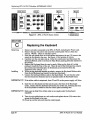
Replacing the Pitch/Mod Wheel Assembly
The Pitch and Mod Wheels are replaced as an assembly along with the main harness
cables.
Removing
Installing
page 32
1. Remove all cables connected to the EPS-16 PLUS, including the Power cord.
2. Remove the four (4) screws that fasten the control panel with a 2.5mm hex
wrench. NOTE: These are machine screws.
3 . Place the unit upside down on a soft surface and remove the four· (4) screws that
attach the Wheel Assembly to the case. See Figure 14 for location of screws.
4. Return the unit to an upright position. Raise the control panel and cut the wire
ties that hold the wire harness to the chassis.
.
5. Disconnect the main harness from the Main Board, the Power Supply, the
Keypad/Display and the line filter. Note that these connectors are keyed and
have connector locks.
6. Carefully lift the Wheel Assembly out of the case.
7. Disconnect the cables from the Disk Drive, paying particular attention to the
polarity.
8. Remove the Disk Drive and place it into the new assembly as described in Section
H Reattach the Disk Drive cables.
9. Connect the new wire harness to:
a. the Main Board (Ill, J13, J15, and ground lug),
b. the Power Supply (J1,J2, J3, and ground wire to the heat sink),
c. the KeypadlDisplay (left sides), and
d. the line filter ground lug
paying particular attention to the alignment of pins and connectors.
10. Reconnect the wire harness to the case using wire ties.
11. Reattach the Wheel Assembly to the case using the four screws.
12. Power up, test the unit, and close the control panel.
EPS-16 PLUS Service Manual
Replacing EPS-J6 PLUS Modules (KEYBOARD ONLY)
SECTION
G
Removing
Installing
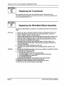
Replacing the Line Filter
1. Remove all cables connected to the EPS-16 PLUS, including the Power cord.
2. Remove the four (4) screws that fasten the control panel with a 2.5mm hex
wrench. NOTE: These are machine screws.
3. Remove the three (3) wires connected to the back of the Filter, paying particular
attention to the polarity.
4. Remove the two (2) screws and nuts that secure the Filter to the case. Note that
there are star washers on the inside only.
5. Install the new Line Filter from outside the case using the two screws, star
washers and nuts.
6. Reconnect the three wires to the Filter, again noting the proper polarity.
IMPO RT ANT! Failure to connect the wires to their proper posts can lead to a potential shock
hazard (see Figure 3).
7. Power up, test the unit, and close the control panel.
SECTION
H
Removing
Installing
Replacing the Disk Drive
1. Remove all cables connected to the EPS-16 PLUS, including the Power cord.
2. Remove the four (4) screws that fasten the control panel with a 2.5mm hex
wrench. NOTE: These are machine .screws.
.
3. Turn the unit over, top down, and remove the four (4) screws that attach the
Wheel assembly to the case. See Figure 14 for location of screws. Return the
unit to an upright position and raise the control panel. Carefully lift the wheel
assembly out of the case.
4. Disconnect the two cables from the Disk Drive, paying particular attention to the
polarity (see p. 2, the Disk Drive).
5. Remove the four (4) screws and star washers that attach the Disk Drive to the
wheel assembly.
6. Carefully slide the Disk Drive out of the wheel assembly.
7. !mIDPJ.iiately place the defective drive in the anti-static bag that the new drive came
m.
8. Slide the new Disk Drive into place and mount it using the four screws and star
washers. Reconnect the two cables, paying particular attention to the alignment
of pins and connectors.
9. Reattach the wheel assembly to the case using the four screws.
10. Power up, test the unit, and close the control panel.
EPS-J6 PLUS Service Manual
page 33
Replacing EPS-J6 PLUS Modules (KEYBOARD ONLY)
NOTES:
page 34
EPS-16 PLUS Service Manual
EPS-16 PLUS RACK ONLY
EPS·16 PLUS RACK
ONLY SECTION
EPS-16 PLUS Service Manual
Contents:
page
Figure 14 PLUS Rack Exploded View
Replacing Modules
A - Rack Main Board . . . . .
B - Rack Keypad/Display Board
C - Rack KPC Simulator Board .
D - Rack Power Supply Board
E - Rack Transformer . . . .
F - Rack OEX-6 Board . . . .
G - Rack Line Filter . . . . .
H - Rack Disk Drive . . . . .
J - Rack Memory Expander Board
36
37
38
39
39
40
40
41
41
42
page 35
-...
Memory Expander Board
Simulator Board
Power Supply Be
~--
--c~_
Disk Drive Mounting Bracket
Figure 16 EPS-16 PLUS Rack Exploded View
page 36
EPS-16 PLUS Service Manual
Replacing EPS-J6 PLUS Modules (RACK ONLY)
SECTION
A
Removing
Installing
Replacing the Rack Main Board
1. Remove all cables connected to the EPS-16 PLUS Rack, including the power
cord.
2. Remove the lid (see below). Remove the OEX-6 board (see Section F steps 3-6).
3. Remove the five (5) 15mm nuts from the rear panel jacks marked Audio In,
Right/Mono, Left/Mono, Pedal-CV, and Ft. Sw.
4. Disconnect all cables from the Main Board.
5. Remove the ten (10) machine screws (and one star washer from the ground pad)
from the Main Board (one screw is located in the middle of the board between
VR6 and C68). See Rack Hardware Notes items #3 and 4 on p. 24.
6. Before installing the new circuit board, make sure the mylar insulator is in place.
7. With the board tilted on a slight angle, insert the jacks into the holes in the rear
panel. Press the board down and into place.
8. Replace the Main Board screws, and secure the jacks with the nuts. Reconnect
the ,cables.
9. Reinstall the OEX-6 board (see Section F) and secure the jacks with the nuts.
10. Power up, test the unit, and reattach the lid (see below).
REMOVING THE LID
Removing
Remove the twenty-two (22) screws that fasten the cover:
1. Remove the one (1) 6-32 machine screw from above the disk drive (about an
inch back from the front panel) that attaches .the cover to the disk drive bracket,
2. Remove the four (4) #8-32 machine screws and star washers from each side
panels of the unit (the ones that could attach the mounting ears).
3. Remove the four (4) 416 x 1/4" self-tapping screws that attach the lid to the front
panel.
4. Remove the nine (9) #5 x 1/4" self-tapping screws that attach the lid to the base:
a. remove two (2) screws from each side of the unit, and
b. remove five (5) from the back of the unit Note that the center screw has a
star washer.
5. Carefully remove the lid from the unit.
REATTACHING THE LID
IMPORTANT! Be :sure to install all screws into the Control Panel with a hand
:screw driver to avoid stripping the holes (see p. 4).
Installing
1. Install the five (5) self-tapping screws on the back of the unit Make sure that
there is a star washer on the center screw.
2. Install the two (2) self tapping screws on either side of the unit
3. Install the one (1) machine screw on the top of the unit located about 1" back from
the control panel.
4. Install the four (4) self-tapping screws on the top of the unit closest to the control
panel.
5. Install the four (4) machine screws and star washers into each side of the unit (the
ones that could attach the mounting ears).
EPS-J6 PWS Service Manual
page 37
Replacing EPS-J6 PLUS Modules (RACK ONLY)
SECTION
B
Removing
Installing
Replacing the Rack Keypad/Display Board
1. Remove all cables connected to the EPS-16 PLUS Rack, including the power
cord.
2. Remove the lid (see Section A).
3. Remove the two cables from the disk drive, three cables from the keypad/display
board, two wires to the power switch, and unplug the headphones cable from the
main board.
4. Carefully tip the unit onto its rearpanel. Remove the four (4) self-tapping screws
and ,one star washer from the bottom of the unit closest to the control panel.
5. Remove the one (1) machine screw from the bottom of the unit located about I"
back from the control panel (this screw goes through the disk drive mounting
bracket inside the unit).
6. Carefully remove the Control Panel from the unit Just enough to unplug the 20pin ribbon cable from the KPC simulator board.
7. Place the Control Panel face down on a soft surface. Remove the eleven (11)
screws that attach the KeypadlDisplay Board to the control panel.
8. See Hardware Notes p. 24. Install the new KeypadlDisplay board onto the new
control panel using the eleven screws.
9. Reconnect the 20-pin ribbon cable to the KPC simulator board before sliding the
new assembly into place (make sure the striped side of the ribbon cable is on pin
1).
IMPORTANT! Reconnect the 20-pin ribbon cable to theKPC simulator board
before sliding the new assembly into place. Be sure to install all
screws into the Control Panel with a hand screwdriver to avoid
stripping the holes (see p. 4).
10. Install the four (4) self-tapping screws (one with a star washer) on the bottom of
the unit closest to the control panel.
11. Install the one (1) machine screw from the bottom of the unit located about 1"
back from the control panel (this screw goes through the disk drive mounting
bracket inside the unit).
12. Connect the two cables to the disk drive, three cables to the keypad/display, two
wires to the power switch (see Figure 2), and plug the headphones cable into the
main board paying particular attention to polarity.
13. Power up, test the unit, and reattach the lid (see Section A).
page 38
EPS-J6 PLUS Service Manual
Replacing EPS-J6 PLUS Modules (RACK ONLY)
SECTION
C
Removing
Installing
Replacing the Rack KPC Simulator Board
l. Remove all cables connected to the EPS-16 PLUS Rack, including the power
cord.
2. Remove the lid (see Section A).
3. Remove the control panel (see Section B) OR remove the transfonner (see Section
E).
4. Disconnect the 20-pin ribbon cable from the KPC simulator board.
5. Pop. the KPC simulator board from the four white standoffs by squeezing the
standoffs.
6. Install the new KPC simulator board onto the standoffs making sure the side of
the board with the 2O-pin connector is closest to the base of the unit.
7. Connect the 20-pin ribbon cable making sure that the striped side is on pin 1.
8. Reinstall the control panel (see Section B) OR the transfonner (see Section E).
9. Power up, test the unit, and reattach the lid (see Section A).
SECTION
D
Removing
Replacing the Rack Power Supply Board
1. Remove all cables connected to the EPS-16 PLUS Rack, including the power
cord.
2. Remove the lid (see Section A).
3. Disconnect the 9-pin cables (Jl, J4), the 6-pin cable (13), and the 4-pin cable (J2)
. from the Power Supply Board. Note that these cables are keyed.
IMPORT ANT! The connector on the 9-pin cable from the transfonner has a high retention force.
Please use a scribe, screwdriver, or similar tool to remove it (see p. 4). Do not
pull on the wires!
Installing
4. Carefully tip the unit onto its rear paneL While holding onto the Power Supply
board with one hand., remove the three screws from the bottom that attach it to the
base.
S. Remove the Power Supply board.
6. Insert the replacement Power Supply Board.
7. Reinstall the Power Supply screws. Carefully reconnect the four cables, paying
particular attention to the alignment of pins and connectors.
8. Power up, test the unit, and reattach the lid (see Section A).
EPS-16 PLUS Service Manual
page 39
Replacing EPS-16 PLUS Modules (RACK ONLY)
SECTION
E
Removing
Installing
Replacing the Rack Transformer
1. Remove all cables connected to the EPS-16 PLUS Rack, including the power
cord.
.
2. Remove the lid (see Section A).
3. Disconnect the transformer cables to the power supply, line filter, and power
switch.
4. Remove the four screws and flat washers that hold the Transfonner in place.
5. Insert the new Transformer and attach it to the base using the four screws and flat
washers.
6. Reattach the cables to the power supply, line filter, and power switch.
7. Power up, test the unit, and reattach the lid (see Section A).
SECTION
F
Removing
Replacing the Rack OEX-6 Board
1. Remove all cables connected to the EPS-16 PLUS Rack, including the power
cord.
2. Remove the lid (see Section A).
3. Disconnect the ribbon cable from the OEX-6 board.
4. Remove the six (6) 15mmnutsfrom the rear panel jacks marked Bus3lRight,
Bus3ILejt, Bus2lRight, Bus21Left, AuxllRight, andAuxllLeft.
Installing
page 40
5. Pop the OEX-6 board from the two white standoffs by squeezing the standoffs.
6. Remove the OEX-6 board from the unit.
7. With the new OEX-6 board tilted on a slight angle, insert the jacks into the holes
in the rear panel and snap the board onto the standoffs.
8. Reconnect the ribbon cable from the main board making sure that the striped side
is on pin 1.
9. Secure the jacks with the nuts.
10. Power up, test the unit, and reattach the lid (see Section A).
EPS-J6 PLUS Service Manual
Replacing EPS-16 PLUS Modules (RACK ONLY)
SECTION
G
Removing
Installing
Replacing the Rack Line Filter
1. Remove all cables connected to the EPS-16 PLUS Rack, including the power
cord.
2. Remove the lid (see Section A).
3. Remove the three (3) wires connected. to the back of the Filter, paying particular
attention to the polarity.
4. Remove the two (2) screws and nuts that secure the Filter to the case. Note that
there are star washers on both sides.
5. Install the new Line Filter from the inside of the base using the screws, star
washers and nuts.
6. Reconnect the three wires to the Filter, again noting the proper polarity.
IMPORTANT! Failure to connect the wires to their proper posts can lead to a potential shock
hazard (see Figure 3).
7. Power up, test the unit, and reattach the lid (see Section A) .
.SECTION
H
Removing
lDstalling
Replacing the Rack Disk Drive
1. Remove all cables connected to the EPS-16 PLUS Rack, including the power
cord.
2. Remove the lid (see Section A). Remove the control panel (see Section B).
3. Disconnect the two cables from the Disk Drive, paying particular attention to the
polarity (see p. 2, the Disk Drive).
4. Remove the four (4) screws that attach the Disk Drive mounting brackets to the
control panel.
5. Remove the four (4) screws that attach the mounting brackets to the Disk Drive.
6. Immediately place the defective drive into the anti-static bag that the new drive
came in.
.
7. Attach the mounting brackets to the new Disk Drive using the four screws.
IMPORTANT! Be sure to install all screws into the Control Panel with a hand
screw driver to avoid stripping. the holes (see p. 4).
8. Attach the mounting brackets to the control panel trying to use the same holes.
9. Attach the control panel to the base (see Section B).
10. Connect the two cables, paying particular attention to the alignment of pins and
connectors.
11. Power up, test the unit, and reattach the lid (see Section A).
EPS-16 PLUS Senlice Manual
page 41
Replacing EPS-J6 PLUS Modules (RACK ONLY)
SECTION
J
Removing··
Installing
page 42
Replacing the Rack Memory Expander Board
1. Remove all cables connected to the EPS-16 PLUS Rack, including the power
cord.
2. Remove the lid (see Section A). Remove the control panel (see Section B).
3. With the front panel close to you, the memory expander board is located in the left
corner of the unit.
4. Remove the screws that attach the memory expander to the base. If the memory
expander board is a REV A, there should only be two screws holding it in. If the
memory expander is a REV B or higher, there should be four screws holding it in
place. See Rack Hardware Notes item #4 on p. 24.
5. Wiggle the memory expander board side to side and up a bit to remove it.
6. Before installing the replacement board, make sure that the connector fingers are
.
clean. If needed, clean them using a pencil eraser.
7. Insert the board fingers into the main board connector.
8. Attach the board to the chassis using the correct number and placement of screws.
See Rack Hardware Notes item #4 on p. 24.
9. Power up, test the unit, and reattach the lid (see Section A).
EPS-J6 PLUS Service Manual