1
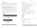
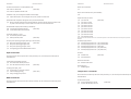
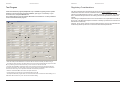
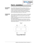
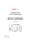
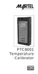
Medlab GmbH
MP01000 User Manual
medlab
Multiparameter OEM Board
for Patient Monitors
MP01000
Technical Manual
Copyright © Medlab 2013
Version 0.97
1
Medlab GmbH
MP01000 User Manual
Medlab GmbH
MP01000 User Manual
Table of Content
Medlab GmbH
Introduction
4
Glossary
4
Physical Units of Data
4
Overview
5
Mechanical Dimensions
6
Board Connectors
7
Specifications
10
General
10
Electrocardiogram
10
Pulse Oximeter
11
Non Invasive Blood Pressure
11
Body Temperature
11
Technical Information ECG
12
Serial Transmission
14
UART Interface
15
CAN Interface
15
Protocol Description
16
Packet Description
16
Command Blocks
26
Board Setup
31
PC Test Program
32
Regulatory Considerations
33
Revisions of this document
34
Helmholtzstrasse 1
76297 Stutensee/Karlsruhe
Phone ++49 7244 741100
[email protected]
www.medlab.eu
2
3
Medlab GmbH
MP01000 User Manual
Introduction
This document describes the hardware and the firmware interface of Medlab's
multiparameter patient monitoring board, the MP01000.
The module can be used to construct a patient monitor to be used from neonate to adult,
while concentrating on housing, design and user interface. The MP01000 handles the
complete interface to the patient, in a safe and certifiable way.
The MP01000 is not a final medical product and carries no CE mark. The module will not
hinder you to confirm with the current relevant standards, but also the part of the system
added by the user has to be designed in a way, so that the complete product can be CE
marked, FDA registered, or safety tested in a test lab.
Glossary
ECG
Lead
Channel
BPM
RPM
SpO2
NIBP
YSI400
UART
CAN
Electrocardiogram
Connection to the patient and one ECG electrode
Waveform showing the differential voltage between two or more
electrodes
Beats per minute (1/min). Unit used to display pulse rates
Respirations per minute (1/min). Unit used to display respiration rate
Saturation pulsatile O2 - the arterial oxygen saturation in %, measured by a
pulse oximeter
Non invasive blood pressure, measured by a cuff around the upper arm
The family of standardized temperature probes used for body temperature
measurement
Universal Asynchronous Receiver Transmitter - Interface type
Controller Area Network - Interface type
Physical Units of Transmitted Data
Transmission speeds for the waves are indicated in Hz (sec-1).
Scaling of ECGs is done in the units "cm/mV" for the Y-axis and in "mm/sec" for the Xaxis.
Standard values for the trace speed are 12.5 mm/sec, 25 mm/sec and 50 mm/sec. The
amount of points needed to reach these speeds depend on the resolution of the user
screen. For example, if one uses an LCD screen with a resolution of 4 dots/mm, a data
rate of 100 Hz is needed to show the waveform with 25 mm/sec.
ECG amplitudes are typically indicated in „cm/mV“. Since this is directly depending on
the resolution of the screen the user is working on, the transmitted samples cannot be
scaled like this, but instead fall into the range of 0-0xFF. It is within the responsibility of
the user to scale the transmitted samples in a way so the waves displayed on his
individual screen fit to the usual scales used in medicine, 0.5, 1, 2, and 4 cm/mV.
Medlab GmbH
Stage 1
1mV = 32
MP01000 User Manual
Stage 2
1mV = 64
Stage 3
1mV = 128
Stage 4
1mV = 256
Respiration rate is transmitted in „rpm“ (respirations per minute).
Pulse rate is transmitted in „bpm“ (beats per minute).
Pressures for NIBP are transmitted in mmHg (1mmHg = 133,322 Pascal)
Temperatures are transmitted in 10*°C, e.g. 388 equals 38.8 °C
Overview
The MP01000 contains a five lead ECG, a pulse oximeter, a part for measuring a
patient's arterial blood pressure, none-invasively, and a two channel thermometer.
The module can work with a five lead ECG cable to show 7 channels of ECG, with a four
lead cable showing 6 channels, and with a three lead cable to show one channel of ECG.
An advanced pulse detection algorithm is integrated.
The module measures the respiration rate of the patient using the impedance change
between the electrodes.
When using a five lead cable, the module can output the following channels
synchronously: I, II, III, aVR, aVL, aVF, C.
When using a four lead cable, the module can output the following channels
synchronously: I, II, III, aVR, aVL, aVF.
When using a three lead cable, the module can output the following channels: I or II or
III.
The non-invasive blood pressure measurement is done using a standard cuff, normally
fitted on the left upper arm of the patient. There are six different cuff sizes available.
SpO2 is measured using an optical transducer that is attached to the patient's finger.
Medlab offers a complete family of transducers, reusable - and single use types, for
adults and neonates.
Temperature is measured using standard YSI400 family temperature probes.
The MP01000 contains all patient-side electronics needed for a complete and small
medical multi-parameter monitor.
The module communicates with a host over a bidirectional serial interface, either of
UART or CAN type. The MP01000 receives commands from the host and streams the
measured patient data back to the host microcontroller. Both sides of the protocol are
block oriented and secured by a CRC checksum present in the data blocks.
Since the module generates a relatively large amount of data, a powerful 32 bit host
microcontroller is required. For example, ARM Cortex M3 or Cortex M4 controllers are
very well suited to receive and decode the data stream and also eventually control a user
interface on a colour LCD or similar.
The amplification of the module in the different amplification stages is:
4
5
Medlab GmbH
MP01000 User Manual
Medlab GmbH
Mechanical Dimensions
MP01000 User Manual
Module Connectors
110
1
TEMP
X4
105,2
5
1
SpO2
X5
JP2
CAN
X1
100
95
94
ECG
X6
1
UART
X2
76,2
All connectors 2.54mm spacing,
1
1
ECG connector 5.12mm spacing
50,8
49,5
56
39,4
POWER
X3
1
16,5
5
105,2
5
106,7
All units in mm.
X1
CAN connector
1
2
3
CAN H
CAN L
GND
CAN bus high line
CAN bus low line
System ground
note: closing JP2 adds a termination resistor to the CAN bus
The test kit version of the board comes with connectors X2-X6 populated, with 90°
angled male connectors. The boards for serial production alone are delivered without any
connectors populated, in order to enable the user to use the type of connector he needs
for his application.
(DXF data of the board is available upon request)
6
X2
UART connector
1
2
3
4
5
6
7
8
9
10
11
12
13
14
15
16
GND
GND
TxD CMOS level
TxD RS232 level
RxD CMOS level
RxD RS232 level
not connected
ISP
GND
GND
R-TRIG
R-TRIG
not connected
not connected
not connected
not connected
System ground
System ground
Serial data output
Serial data output
Serial data input
Serial data input
In system programming, used for firmware update
System ground
System ground
R-wave hardware trigger
R-wave hardware trigger
7
Medlab GmbH
MP01000 User Manual
MP01000 User Manual
Patient Cable Connection
X3
Power Connector
1
2
3
VCC, 7-15VDC
Power Down
GND
X4
Temperature transducer Connector
1
2
3
4
5
6
CH1
IGND
CH2
IGND
IGND
ISet
Power supply of the board
Connect to GND to power down the complete board
System ground
YSI400 probe 1
Patient ground
YSI400 probe 2
Patient ground
Patient ground
Enables EEPROM programming when shorted to IGND
Probe1 is connected to IGND and CH1 pin, probe 2 to IGND and CH2 pin. ISet is left open during
normal operation.
X5
SPO2 Probe Connector
1
2
3
4
5
6
7
PH1
PH2
RSEN
IGND
LED1
LED2
PDAT
Photodiode positive input probe pin (DSUB pin 5)
Photodiode negative input probe pin (DSUB pin 9)
RSEN pin of probe (DSUB pin 1)
Shield of probe cable, Patient ground (DSUB pin 6 and 7)
LED1 pin of probe (DSUB pin 3)
LED2 pin of probe (DSUB pin 2)
PDAT pin of probe (DSUB pin 4)
The SpO2 probe has a male Dsub 9 connector. The pin numbering for connecting the probe to
the board can be found in the table above. The internal connecting cable between probe and
SpO2 connector should be kept as short as possible.
Depending on the RF immunity level your final product needs to fulfil (3V/m or 20V/m), it might be
necessary to include further EMC filtering measures close to the SpO2 connector input of your
medical device. Please contact Medlab for details.
X6
ECG cable Connector
1
2
3
4
5
6
7
C-IN
SHIELD
LL-IN
RA-IN
LA-IN
SHIELD
RL-IN
8
Medlab GmbH
Chest electrode
Patient ground
Left Leg electrode
Right Arm electrode
Left Arm electrode
Patient ground
Right leg electrode
ECG cable
The module can be connected to the patient using a three lead, four lead or five lead
ECG cable. Depending on cable, one to seven channels of ECG can be measured.
Three Lead Patient Cable
Five Lead Patient Cable
Four Lead Patient Cable
Chest
Shield
Shield
Shield
Left Leg
Left Leg
Right Arm
Right Arm
Left Arm
Left Arm
Left Leg
Right Arm
Left Arm
Shield
Shield
Shield
Right Leg
Right Leg
I or II or III
I and II and III
and aVL and aVR and aVF
I and II and III
and aVL and aVR and aVF and C
SpO2 Transducer
The module can work with all Medlab PEARL SpO2 probes. There are reusable - as well
as disposable types. Please see the separate catalog available for the probes. The
module cannot work with other manufacturers’ SpO2 probes. The probes have a male
DSUB 9 connector, that needs to be connected to the board using an adapter between
connector X5 and the probe plug. For prototypes, these adapters are available from
Medlab. For series production, as each device requires another length, you should
produce your own adapter cables. Also flexible PCBs are a good solution for this
adapter.
NIBP Cuffs
While it is not mandatory to use Medlab cuffs for NIBP measurement, best accuracy is
reached when using them, as the module's algorithm is developed for the mechanical
dimensions of the bladders in the NIBscan cuffs. Also, clinical validation has been done
with these cuffs.
Temperature probes
All probes that are compatible with the YSI 400 family resistance specifications can be
used. However, the manufacturer of the probe should be selected with care, as the
accuracy of the clinical thermometer directly depends on the accuracy of the
temperature/resistance curve of the probe.
9
Medlab GmbH
MP01000 User Manual
Medlab GmbH
Specifications
SpO2
General
Measuring range SpO2:
Accuracy SpO2:
Mechanical size:
110 mm x 100 mm
4 layer PCB, thickness 1.6 mm
Maximum height:
33 mm without ECG respiration option, 40 mm with
respiration option
Attachment:
four M3 screws in the corners of the PCB
Weight:
175 g
Operating voltage:
7 - 15 V DC
Power consumption:
980 mW while NIBP not measuring (with respiration)
940 mW while NIBP not measuring (without respiration)
max. 2000 mW during NIBP pump up
max. 1200 mW during NIBP measurement (pump off)
Temperature:
Humidity:
Storage
Operation
Storage
Operation
-30 °C to 90 °C
-20 °C to 50 °C
0 .. 95 %, non condensing
5 .. 95 %, non condensing
ECG
Input ECG:
Patient isolation:
Leakage current:
Amplification:
Data transmission:
Mains filter:
Other filters:
Amplifier frequency range:
Age modes:
ECG modes:
Lower edge frequency:
Upper edge frequency:
QRS detection:
Respiration detection:
Pacemaker:
Output:
10
Defibrillation protected
4000 Volts RMS
Better than class CF requirements (<10 µA)
Four stages, user selectable
Four data output rates, user selectable
50 Hz, 60 Hz or no notch filter
EMG filter (can be turned on or off)
0.05 to 70 Hz
Adult - and neonatal mode
Diagnostic- and monitoring mode
0.67 Hz (monitoring) or 0.05 Hz (diagnostic)
40 Hz (monitoring) or 70 Hz (diagnostic)
30 .. 247 bpm +- 1%, +- 1 Digit, 12 beat average
5 .. 99 rpm +-3%, +- 1 Digit, 8 samples average
(option)
Pacemaker detector +/-2mV to +/-700mV, 0.5-2ms pulse
width, (can also be turned off)
Separate, adjustable pulse trigger output, (0...5 V level)
Trigger output also fully isolated from patient side
MP01000 User Manual
Averaging SpO2:
0 %..100 % of SpO2
90 %..100 % :
1 % , +/- 1 digit
80 %..89 %
:
2 % , +/- 1 digit
70 %..79 %
:
3 % , +/- 1 digit
70 %..100 % :
2 % , +/- 1 digit
below 70 %
:
not specified
user selectable in three stages
Measuring range pulse:
Accuracy pulse rate:
Averaging pulse rate:
30 .. 249 bpm of pulse rate
+/- 1%, +/- 1 Digit
follows SpO2 averaging
NIBP
Meas. range for adults:
SYS
25 - 280 mmHg
DIA
10 - 220 mmHg
MAP
15 - 260 mmHg
Meas. range for neonates: SYS
20 - 155 mmHg
DIA
5 - 110 mmHg
MAP
10 - 130 mmHg
Accuracy, abs. pressure: +/- 2 mmHg
Accuracy algorithm:
< +/- 5 mmHg for mean value
<
8 mmHg standard deviation
Pulse rate range:
30 - 230 bpm
Leakage rate:
< 3 mmHg / minute
Overpressure limits:
290 mmHg adult mode
150 mmHg neonatal mode
Temperature
Channels:
2 temperature channels, 1 reference channel (38.8 °C)
Probes:
Compatible with all YSI series 400 probes
Accuracy:
+- 0.1 °C for an ambient Temperature of 10 °C to 40 °C
Measurement range:
25.0 .. 50.0 °C
Warm up time:
less than 30 seconds
11
Medlab GmbH
MP01000 User Manual
Technical description for TRF IEC 60601-2-27:
When preparing a test report form (TRF) for proof of compliance of the users medical product to
IEC60601-2-27, the following remarks / technical data will be helpful or needed:
Input Impedance:
Common mode rejection ratio:
Input Dynamic Range:
Defibrillator Discharge Recovery:
Leads-off sensing current:
> 10 MOhm
> 90 dB at 50 Hz or 60 Hz
±5 mV AC, ±300 mV DC
<10 sec per IEC 601-2-27
<10 sec per AAMI EC13-1992
Applied currents less than 150 nA
The following information references particular sections of IEC and EN 60601-2-27:
Respiration (optional) Section 6.8.2.bb.1)
Applied currents less than 80 µA @ 90kHz square
Tall T-wave rejection. Section 6.8.2.bb.2)
T-wave of 1.2 mV amplitude will not affect heart rate determination.
Heart rate averaging. Section 6.8.2.bb.3)
The pulse rate is averaged over the last 12 detected pulses.
QRS Detection (various sections)
If the MP01000 is set to adult mode, the heart rate meter will not respond to ECG signals having a
QRS amplitude of 0,15 mV or less, or R-waves of a duration of 10 ms or less, with an amplitude of 1
mV.
The detection range of QRS amplitudes is 0,5 mV to 5 mV, for durations of the QRS complex ranging
from 50 ms to 120 ms, up to a signal rate of 300 BPM.
If the MP01000 is set to neonatal mode, the detection range of QRS amplitudes is 0,5 mV to 5 mV,
for durations of the QRS wave ranging from 40 ms to 120 ms, up to a signal rate of 350 BPM.
Response to irregular rhythm. Section 6.8.2.bb.4)
A1) Ventricular bigeminy: the MP01000 counts both large and small QRS complexes to display a rate
of 80 bpm.
Medlab GmbH
MP01000 User Manual
Pacemaker pulse display capability (See IEC 601-2-27 clause 50.102.12)
The MP01000 is capable of displaying the ECG signal in the presence of
pacemaker pulses with amplitudes of ±2 mV to ±700 mV and durations of
0.5 ms to 2.0 ms. An indication for the pacemaker pulse is provided.
Pacemaker pulse rejection (See IEC 601-2-27 clause 50.102.13)
Without over- and undershoot (rectangular pulse):
a) For single (ventricular-only) pacemaker pulses alone, with 0.1 and 2.0 ms pulse-widths and ±2 mV
and ± 700 mV pulse-amplitudes, the MP01000 correctly displays the heart rate as zero bpm
(Asystole).
b) For single (ventricular-only) pacemaker pulses with normally paced QRS-T, with 0.1 and 2.0 ms
pulse-widths and ±2 mV and ± 700 mV pulse-amplitudes, the MP01000 correctly displays the heart
rate of the QRS-T rhythm (60 bpm for the specified test waveform).
c) For single (ventricular-only) pacemaker pulses with ineffectively paced QRS pattern, with 0.1 and
2.0 ms pulse-widths and ±2 mV and ± 700 mV pulse-amplitudes, the MP01000 correctly displays the
heart rate of the underlying QRS-T rhythm (30 bpm for the specified waveform).
d) For atrial/ventricular pacemaker pulses alone, with 0.1 and 2.0 ms pulse-widths and ±2 mV and ±
700 mV pulse-amplitudes, the MP01000 correctly displays a heart rate of zero bpm (Asystole).
e) For atrial/ventricular pacemaker pulses with normally paced QRS-T, with 0.1 and 2.0 ms pulsewidths and ±2 mV and ± 700 mV pulse-amplitudes, the MP01000 correctly displays the heart rate of
the QRS-T rhythm (60 bpm for the specified test waveform).
f) For atrial/ventricular pacemaker pulses with ineffectively paced QRS pattern, with 0.1 and 2.0 ms
pulse-widths and ±2 mV and ± 700 mV pulse-amplitudes, the MP01000 correctly displays the heart
rate of the underlying QRS-T rhythm (30 bpm for the specified test waveform).
With over and undershoot:
A2) Slow alternating ventricular bigeminy: the MP01000 counts both large and small QRS complexes
to display a rate of 60 bpm.
a) For single (ventricular-only) pacemaker pulses alone, with 0.1 and 2.0 ms pulse-widths and ±2 mV
and ± 700 mV pulse-amplitudes, the MP01000 correctly displays a heart rate of zero bpm (Asystole).
A3) Rapid alternating ventricular bigeminy: the MP01000 counts all QRS complexes to display a rate
of 120 bpm.
b) For single (ventricular-only) pacemaker pulses with normally paced QRS-T, with 0.1 and 2.0 ms
pulse-widths and ±2 mV and ± 700 mV pulse-amplitudes, the MP01000 correctly displays the heart
rate of the QRS-T rhythm (60 bpm for the specified waveform).
A4) Bi-directional systoles: the MP01000 counts all QRS complexes to display a rate of 90 bpm.
Heart rate meter response time. Section 6.8.2.bb.5)
a) Change from 80 to 120 BPM: 4 sec
b) Change from 80 to 40 BPM: 7 sec
Time to alarm for tachycardia. Section 6.8.2.bb.6)
Waveform B1:
Amplitude
0,5 mV
1 mV
2 mV
Waveform B2
Amplitude
1 mV
2 mV
4 mV
12
c) For single (ventricular-only) pacemaker pulses with ineffectively paced QRS pattern, with 0.1 and
2.0 ms pulse-widths and ±2 mV and ± 700 mV pulse-amplitudes, the MP01000 correctly displays the
heart rate of the underlying QRS-T rhythm (30 bpm for the specified waveform).
d) For atrial/ventricular pacemaker pulses alone, with 0.1 and 2.0 ms pulse-widths and ±2 mV and ±
700 mV pulse-amplitudes, the MP01000 correctly displays a heart rate of zero bpm (Asystole).
Time to alarm
1 sec
1 sec
1 sec
time to alarm
1 sec
1 sec
1 sec
e) For atrial/ventricular pacemaker pulses with normally paced QRS-T, with 0.1 and 2.0 ms pulsewidths and ±2 mV and ± 700 mV pulse-amplitudes, the MP01000 correctly displays the heart rate of
the QRS-T rhythm (60 bpm for the specified test waveform).
f) For atrial/ventricular pacemaker pulses with ineffectively paced QRS pattern, with 0.1 and 2.0 ms
pulse-widths and ±2 mV and ± 700 mV pulse-amplitudes, the MP01000 correctly displays the heart
rate of the underlying QRS-T rhythm (30 bpm for the specified test waveform).
13
Medlab GmbH
MP01000 User Manual
Serial Transmission
The host connection to the board is a serial communication interface. By default, transmission is
over an asynchronuous, UART style interface, operating at 115200 baud, 8 data bits, no parity bit
and one stop bit. Both CMOS and RS232 (+/- 5 Volt level) voltage levels are available on the
connector. The RS232 voltage levels are helpful during evaluation of the board, which can be
done using an ordinary PC and a special software. The connection in the customer's final system
will typically be done through 0V/5V levels, which saves electronic components on the host side of
the data stream.
Optionally, the board can also communicate with the host over a CAN interface, at 250k, 500k and
1000k bit transmission rate.
The MP01000 sends data and receives commands. For both CAN and UART mode, the protocol
is block oriented.
In UART mode, the block begins with a start sequence, consisting of a start character, a one byte
data length counter, and a 16 bit block identifier. This header is followed by a payload block of
zero to 8 bytes length. The payload data is followed by a one byte CRC checksum and an end
character.
Transmission can be started and stopped with "TXDON" and "TXDOFF" command sent by the
host.
In UART mode, the module starts sending data automatically after power up and selftests are
finished.
In CAN mode, the content of the payload block is identical to the data blocks in UART mode, but
the role of the block identifier mentioned above is actually taken over by the 11 bit CAN identifier.
Since the multiparameter board generates a lot of data, priority of the CAN identifiers have to be
relatively high (this means low values for identifiers), and consequently, only 11 bit identifiers are
supported. Of course, other devices on the CAN bus can use 29 bit identifiers transparently. CRC
bytes, start of block and end of block, as well as data length code, are handled automatically by
the CAN bus controller of the host.
Transmission can be started and stopped with "TXDON" and "TXDOFF" command sent by the
host.
In CAN mode, the module does not start to send automatically after power up. Instead, it waits for
the first "TXDON" command, please see description on page ###.
CAN mode is more complicated compared to UART mode, so if your application does not require
CAN for technical reasons, we recommend to work using UART mode. The CRC checksum of
each block also enables a very reliable and secure data transmission in UART mode.
The neutral line of all waveforms is located at 128 (0x80), since the module transmits unsigned
data.
If blocks contain numbers of more than 8 bits length, the lower byte is always transmitted first in
the block (little endian).
To set the board to either CAN or UART mode, and to set the CAN speed and the block
identifiers, please refer to the chapter "Board setup" of this manual. After delivery, the board
defaults to UART mode, base address ECG 0x0100, base address data blocks 0x0200, and base
address for command blocks 0x0300.
14
Medlab GmbH
MP01000 User Manual
UART mode block
Header
STX (0x02)
Bytecount
Data Block (Payload data)
Identifier low Identifier high Data (1-8 Byte)
End
CRC8
ETX(0x03)
STX: Start of block character (0x02)
Bytecount: Number of bytes in the data block, plus 0xA0. E.g. 0xA5 is 5 bytes
Identifier: Each type of data block uses another block identifier. Must be <2048, same as Object identifier for CAN
Data: The data to be transmitted, variable length. Command acknowledge or error blocks have a data length of 0
CRC8 checksum of the 4 byte header and the data block. Polynom: x^8+x^5+x^4+x^0
ETX: End of block character (0x03)
CAN mode block
DLC
Object Identifier
Data Block (Payload data)
Data (1-8 Byte)
DLC: Data length code, number of bytes in the data block. Host reads this from his CAN controller
Object Identifier: CAN bus address, also sets priority of data block. Host reads this from his CAN controller
Data: CAN bus data block. Host reads this from his CAN controller
UART Interface
The host UART has to be initialized for a baud rate of 115200 baud, 8 data bits, no parity bit and
one stop bit.
The host has to wait for the STX character, verify that the next byte is a value between 0xA0 (0
byte block length) and 0xA8 (8 bytes block length) and then receive the full data block. After this,
the host has to generate the one byte CRC checksum from the STX character to the last data
block byte, and compare the result with the received CRC byte. If they have the same value, the
block is valid. The host can then decode the received block according to the detailed descriptions
of the data block content on the following pages. The polynom used for the CRC generation is x^8
+ x^5 + x^4 + x^0. Since the bases addressed in UART mode do not have any special meanings
for priorities, as the object identifiers in CAN mode have, it does not make a lot of sense to set
them to custom values. It is, however, possible. Transmission of data can be completely turned off
by the TXDOFF command, and reenabled by the TXDON command. The board board defaults to
TXDON after power up.
CAN Interface
The host CAN controller has to be initialized to 250k, 500k or 1000k bit speed, and the object
identifiers described on the next pages have to be added to the acceptance filter of the host's
CAN controller.
The host then has to issue a "TXDON" command, and will then start to receive data blocks.
The host has to wait for his CAN controller to signal a successful reception of a CAN block. The
host can then decode the received block, according to the detailed descriptions of the data block
content on the following pages. The board defaults to TXDOFF after power up.
Object Identifiers (CAN) - Identifier low/high (UART)
Because the object identifiers in CAN mode are directly responsible for the priority of the message
on the bus, the basic address of the identifiers can be set by the user in three groups, ECG block
base address, host block base address and command block base address. This has been split
into three groups, the ECG blocks should have the highest priority (lowest identifier), because the
amount of data sent is largest for the ECG wave blocks. The second user adjustable address is
the base address for all data blocks to the host, except the ECG blocks, and the third address is
the base address used for commands sent to the board by the host.
15
Medlab GmbH
MP01000 User Manual
Serial Transmission Protocol
After the host has received the blocks, either over UART - or CAN interface, the data block
descriptions on the next pages can be used for decoding.
ECG Blocks
The board transmits up to 7 ECG waveforms, and an impedance respiration waveform.
The transmitted channels that are available with a five lead cable are:
1)
2)
3)
4)
5)
6)
7)
8)
I, Einthoven Lead
II, Einthoven Lead
III, Einthoven Lead
aVR, Goldberger Lead
aVL, Goldberger Lead
aVF, Goldberger Lead
C1, one Wilson lead that should be placed on the chest of the patient
Respiration curve
The module works with a three lead-, a four lead- or a five lead cable. Only parts of the maximum
number of channels can be measured if not all five electrodes are connected (see page 7).
The board contains a lead-off detection that gives information about each single non-connected
electrode.
It is not possible for the module to automatically detect which ECG cable is connected, since the
situation is the same whether, for example, a three lead cable or a five lead cable with two nonattached leads is used.
It is recommended for the user to use a connection system with coded cables (shorted, unused
pins in the connector for example), to make the host system aware of which cable style currently is
connected to the ECG part and to ignore lead-off messages that do not exist for the respective
cabling system. The simplest solution is to have the end-user select which cable is connected in a
menu entry in the host's user interface.
Channels that are requested by the host but cannot be measured, because of no electrode
contact or the respective lead missing in the cable, are transmitted as "0x80", neutral line.
The module features an adult and a neonatal mode.
In adult mode, pulse rates up to 300 bpm are detected. Pulse rates of more than 248 are output as
248 bpm. QRS complexes of 50 ms width and less are not counted as pulses.
In neonatal mode, pulse rates up to 350 bpm are detected and rates of more than 249 are output
as 248 bpm. QRS complexes of 50ms down to approximately 20 ms width are counted as pulses.
These differences in adult- and neonatal pulse detection are a requirement of the newest ECG
monitoring standard.
Medlab GmbH
MP01000 User Manual
ECG Blocks
ECGWAVE BLOCK (1 to 8 bytes long)
Identifier: ECGBaseaddress+0x00 (default: 0x100)
Wavesample Wavesample Wavesample Wavesample Wavesample Wavesample Wavesample Wavesample
1
2
3
4
5
6
7
8
Wavesample
1
Wavesample
2
.....
Byte 1
8 bit sample value curve 1, in straight binary, neutral line at 0x80
Byte 2
8 bit sample value curve 2, in straight binary, neutral line at 0x80
Byte n
note: the amount of curves transmitted depend on the last curve selection command
ECGWAVE blocks are sent 50, 100, 150 or 300 times per second, depending on the last ECG speed command
Power on default is 100 blocks per second
ECGNUM BLOCK (2 bytes long)
Identifier: ECGBaseaddress+0x01 (default: 0x101)
Pulse [1/min]
Resp. rate
[1/min]
Pulse [1/min]
Byte 1
8 bit pulse rate value, in bpm, e.g. 1/min
Resp. rate
[1/min]
Byte 2
8 bit respiration rate value, in rpm, e.g. 1/min
ECGNUM blocks are sent once after each detected pulse, and can also be used to generate a pulse "beep" on the host
ECGSTAT BLOCK (4 bytes long)
Identifier: ECGBaseaddress+0x02 (default: 0x102)
Electrodes
Channels
Status 1
Electrodes
Byte 1
0
Channels
Byte 2
0
Status 1
Byte 3
Status 2
Byte 4
Status 2
Bit 7
Bit 6
Bit 4
Bit 3
Bit 2
Bit 1
Bit 0
aVF
transmitted
Chest lead
connected
aVL
transmitted
Right arm
connected
aVR
transmitted
Left arm
connected
Einthoven III
transmitted
Right leg
connected
Einthoven II
transmitted
Left leg
connected
Einthoven I
transmitted
N1
N0
EMG filter on
A1
A0
S1
S0
Neonatal
mode
X
X
ST3
ST2
ST1
ST0
resp. wave
transmitted
C1
transmitted
0
0
X
ECGSTAT blocks are transmitted once per second
Notch filter
N1..N0
00
01
10
11
Notch filter off
50 Hz filter on
60 Hz filter on
reserved
The default settings after power up are:
100 wave blocks per second, I,II,III activated, 1cm/mV amplification, monitoring bandwidth, 50 Hz
filter active. The host can adjust this to its needs by sending commands to the module.
Amp
A1..A0
00
01
10
11
16
Bit 5
Amplification stage 1 (lowest)
Amplification stage 2
Amplification stage 3
Amplification stage 4 (highest)
ECG stat
ST3..ST0
0000
0001
0100
0101
1000
1010
....
Speed
S1..S0
00
01
10
11
Normal operation
Normal operation, pacemaker detected
Initializing
Searching for electrodes
Simulated output
Selftest error
Rest unused, but reserved
50 wave blocks per second
100 wave blocks per second
150 wave blocks per second
300 wave blocks per second
17
Medlab GmbH
MP01000 User Manual
SpO2 Blocks
Medlab GmbH
MP01000 User Manual
SpO2 Blocks
The board transmits the SpO2 waveform (plethysmogram), a data block, and an Spo2 status block.
The module works with all Medlab PEARL SpO2 probes, reusable - and disposable probe types,
please see catalog of probes for available types.
After a probe is connected and a finger is detected, the board sends 50 or 100 waveform blocks
per second, containing the plethysmographic waveform of the pulse oximeter. Transmission speed
of the plethysmogram can be adjusted by sending an "S0" or "S1" command.
The arterial oxygen saturation and the pulse rate are transmitted once per detected pulse, directly
after detection took place. The reception of this block can therefore be used to generate a "pulse
beep" on the host. Also the status block is transmitted once per detected pulse, directly after the
data block.
The perfusion index in the status block gives an indication for the perfusion at the measurement
site. The table on the next page explains the meaning of the different stages of perfusion. This is
important, because the plethysmogram is automatically scaled. Therefore, the height of the
plethsymogram is not a direct indication for the perfusion at measurement site.
SPO2WAVE BLOCK (1 byte long)
Plethysmogram
Plethysmogram
Byte 1
8 bit sample value plethysmographic waveform, in straight binary, neutral line at 0x80
SPO2WAVE blocks are transmitted 100 times per second
SPO2NUM BLOCK (2 bytes long)
SpO2 [%]
Pulse [1/min]
SpO2 [%]
Byte 1
8 bit SpO2 value, in %
Pulse [1/min]
Byte 2
8 bit pulse rate value, in bpm, e.g. 1/min
SPO2NUM blocks are sent once after each detected pulse, and can also be used to generate a pulse "beep" on the host
If no finger is in the probe or no probe is connected, the waveform transmitted is a flat line. The
value package and the status package are in this case transmitted once per second. Oxygen
saturation and pulse rate are set to zero, and the info byte contains either the "No sensor" or "No
signal" info.
SPO2STAT BLOCK (3 bytes long)
Status
Quality
Perfusion
Bit 7
Bit 6
Bit 5
Bit 4
Bit 3
Bit 2
Bit 1
Bit 0
Status
Byte 1
0
S6
S5
S4
S3
S2
S1
S0
Quality
Byte 2
0
0
0
0
Q3
Q2
Q1
Q0
Perfusion
Byte 3
0
0
0
0
0
P2
P1
P0
Perfusion
P2..P0
000
001
010
011
100
101
110
111
unused
< 0.25%
0..25-0.5%
0.5-1.0%
1.0-2.0%
2.0-4.0%
4.0-8.0%
> 8.0%
SPO2STAT blocks are sent once after each detected pulse
Status
S6..S0
0000000
0000001
0000010
0000011
1000101
Quality
Q3..Q0
18
0x00
0x01
0x02
0x03
0x45
OK
No probe detected
No finger in probe
Low perfusion
Selftest error
AC/DC ratio
AC/DC ratio
AC/DC ratio
AC/DC ratio
AC/DC ratio
AC/DC ratio
AC/DC ratio
Quality is a number between 0 and 10,
coded into the lower four bits of status
byte 2. If the number is 0, ten or more
consecutive pulses have been detected
without artefact or other problems. Zero
therefore means best quality.
19
Medlab GmbH
MP01000 User Manual
Medlab GmbH
MP01000 User Manual
NIBP Blocks
NIBPTIMER BLOCK (4 bytes long)
Measurements of NIBP must be individually started by sending the relevant command to the NIBP
board. Alternatively, the board can be set to "cycle" mode. Then, a measurement is automatically
started after the selected time frame has passed.
For measurements on neonates, the board must be set to "neonatal mode". For adults, children
and infants, the board should be set to "adult mode".
During measurement, the current cuff pressure is transmitted five times per second, and can be
used to indicate cuff pressure to the user with a bargraph or a similar indicator on the user
interface of the device.
During measurement, a "break command" immediately stops measurement and deflates the cuff.
Directly after a measurement has ended, a NIBPNUM block is transmitted, together with a status
block. If errors have been detected during measurement, the pressure values and pulse rate in the
NIBPNUM block are set to zero. NIBPNUM and status blocks are then repeated every ten
seconds. Also sent every ten seconds is a NIBPTIMERBLOCK. This block indicates how old the
values in the NIBPNUMBLOCK are. It is a common feature of monitors to blank out measurements
that are older than a certain amount of time, not to mislead the user about the current NIBP values
of the patient, that might be already totally different. The second value in the timer block indicates
the time until the next measurement is automatically started, when in cycle mode.
NIBP Blocks
Pressure low
byte
Pressure
high byte
Pressure
high byte
Byte 1
16 bit value of current pressure in NIBP cuff, in mmHg, low byte part
Byte 2
16 bit value of current pressure in NIBP cuff, in mmHg, high byte part
NIBPCURRENTCUFFPRESSURE BLOCKS are only transmitted during ongoing measurements, 5 times per second
NIBPNUM BLOCK (7 bytes long)
Sys low
Sys high
MAP low
MAP high
Time since
meas. low
Time since
meas. high
Time to cycle
low
Time to cycle
high
Time meas. Time to cycle Time to cycle
high
low
high
Byte 1
16 bit value, time passed since last measurement, in seconds, low byte
Byte 2
16 bit value, time passed since last measurement, in seconds, high byte
Byte 3
16 bit value, time until next measurement, in seconds, low byte (0 if no cycle mode active)
Byte 4
16 bit value, time until next measurement, in seconds, high byte (0 if no cycle mode ac
NIBPTIMER BLOCKS are transmitted after each measurement, and then every ten seconds
NIBPSTAT BLOCK (4 bytes long)
State
Adult/Neo
Cycle
Error
Bit 7
Bit 6
Bit 5
Bit 4
Bit 3
Bit 2
Bit 1
Bit 0
S0
State
Byte 1
0
0
0
0
0
S2
S1
Adult/Neo
Byte 2
0
0
0
0
0
0
0
A0
Cycle
Byte 3
0
C6
C5
C4
C3
C2
C1
C0
Error
Byte 4
0
0
0
0
E3
E2
E1
E0
NIBPSTAT BLOCKS are transmitted after each measurement, and then every ten seconds
NIBPCURRENTCUFFPRESSURE BLOCK ( 2 bytes long)
Pressure low
byte
Time meas.
low
Dia low
Dia high
Pulse rate
Sys low
Byte 1
16 bit value of measured systolic pressure, in mmHg, low byte
Sys high
Byte 2
16 bit value of measured systolic pressure, in mmHg, high byte
MAP low
Byte 3
16 bit value of measured mean arterial pressure, in mmHg, low byte
MAP high
Byte 4
16 bit value of measured mean arterial pressure, in mmHg, high byte
Dia low
Byte 5
16 bit value of measured diastolic pressure, in mmHg, low byte
Dia high
Byte 6
16 bit value of measured diastolic pressure, in mmHg, high byte
Pulse rate
Byte 7
8 bit value of measured pulse rate, in bpm (1/min)
State
S2..S0
000
001
010
011
100
101
110
111
Auto test in progress (only during boot)
Wait for command, no cycle mode
Error, see bits E3..E0 for details
Measuring in progress
Manometer mode
Initializing
Reserved
Leakage test in progress
Error
E3..E0
0000
0001
0010
0011
0100
0101
0110
0111
1000
1001
1010
1011
1100
1101
1110
1111
0x00
0x01
0x02
0x03
0x04
0x05
0x06
0x07
0x08
0x09
0x0A
0x0B
0x0C
0x0D
0x0E
0x0F
No error
Reserved
Autotest failed
No error
Reserved
Reserved
Cuff fitted too loosely or not connected
Leakage (including sudden occurance)
Faulty slow loss of pressure
No pulse detected (cuff incorrectly fitted)
Measurement range exceeded
Movement artefacts too strong
Excess pressure (according to IEC limits)
Pulse signal too large
Leakage during leakage test
System error
Adult/Neo
A0
0
1
Cycle
C6..C0
0000000
0000001
0000010
0000011
0000100
0000101
0001010
0001111
0011110
0111100
1011010
Adult mode
Neonatal mode
0x00 (0)
0x01 (1)
0x02 (2)
0x03 (3)
0x04 (4)
0x05 (5)
0x0A (10)
0x0F (15)
0x1E (15)
0x3C (60)
0x5A (90)
No cycle selected
1 minute cycles selected
2 minutes cycles selected
3 minutes cycles selected
4 minutes cycles selected
5 minutes cycles selected
10 minutes cycles selected
15 minutes cycles selected
30 minutes cycles selected
60 minutes cycles selected
90 minutes cycles selected
NIBPNUM BLOCKS are transmitted after each measurement, and then every ten seconds
20
21
Medlab GmbH
MP01000 User Manual
Medlab GmbH
MP01000 User Manual
Temperature Blocks
Temperature Blocks
The MP01000 can be connected to up to two probes of the YSI400 temperature probe series, to
measure up to two body temperatures.
Measurement range is 20.0-45.0 °C. Outside this temperature window, the respective channel will
report a "too low" or "too high" error in the status block. Also an open input is indicated in the
status block. The board has a status channel, that always should read as 38.8°C.
Each board is individually calibrated, and the calibration constants are stored in two copies in an
EEPROM on the board. If CRC check of both copies fails, a calibration lost error is given in the
status block. This error is fatal, the board has to be resent for recalibration.
Temperature and status blocks are sent once per second, by default. Using a command, this rate
can be increased to five blocks per second.
TEMPNUM BLOCK (6 bytes long)
Temperature Temperature Temperature Temperature Temperature Temperature
1 low
1 high
2 low
2 high
ref. Low
ref. High
Temperature
1 low
Temperature
1 high
Temperature
2 low
Temperature
2 high
Temperature
ref. Low
Temperature
ref. High
Byte 1
16 bit value of measured temperature channel 1, in °C * 10, low byte
Byte 2
16 bit value of measured temperature channel 1, in °C * 10, high byte
Byte 3
16 bit value of measured temperature channel 2, in °C * 10, low byte
Byte 4
16 bit value of measured temperature channel 2, in °C * 10, high byte
Byte 5
16 bit value of measured temperature in reference channel , in °C * 10, low byte
Byte 6
16 bit value of measured temperature in reference channel , in °C * 10, high byte
TEMPNUM blocks are sent once per second or five times per second, depending on the last temperature "speed" command
Power on default is 1 block per second
TEMPSTAT BLOCK (3 bytes long)
Status
channel 1
Status
channel 1
Status
channel 2
Status
channel ref
Status
channel 2
Status
channel ref
Byte 1
8 bit value status channel 1,
Byte 2
8 bit value status channel 2
Byte 3
8 bit value status reference channel
TEMPSTAT blocks are sent once per second
Status
0000000
0000001
0000010
0000011
0000100
22
0x00
0x01
0x02
0x03
0x04
OK
No probe detected
Temperature too low
Temperature too high
Calibration lost
23
Medlab GmbH
MP01000 User Manual
Status Blocks
The MP01000 has a few blocks that are not related to a parameter, but rather refer to the module
in general (general blocks). They are only transmitted after they have been requested by the user.
They include individual serial number of the board, status of the board and firmware versions of
the different subsystems. For details, please see the following page.
Medlab GmbH
MP01000 User Manual
General Blocks
GENERALSTAT BLOCK (6 bytes long)
Internal 1
Internal 2
Internal 1
Byte 1
8 bit value, internal use only
Internal 2
Byte 2
8 bit value, internal use only
Internal 3
Byte 3
8 bit value, internal use only
Internal 4
Host overrun
error counter
Command
error counter
Internal 3
Internal 4
Host overrun Command
error counter error counter
Byte 4
8 bit value, internal use only
Byte 5
8 bit value, command lost, host sent two consecutive commands to fast
Byte 6
8 bit value, counts unknown commands, frame - and crc errors during reception
GENERALSTAT blocks are sent once only after an "MPS" command has been sent by the host
VERSION BLOCK (4 bytes long)
Board
version
ECG version NIBP Version
SPO2
Version
Board
version
Byte 1
8 bit value, version of multiparameter board firmware
ECG version
Byte 2
8 bit value, version of ECG firmware
NIBP Version
Byte 3
8 bit value, version of NIBP firmware
SPO2
Version
Byte 4
8 bit value, version of SpO2 firmware
VERSION blocks are sent once only after an "MPV" command has been sent by the host
SERNUM BLOCK (4 bytes long)
Byte 1
Byte 2
Byte 3
Byte 4
Byte 1
Byte 1
32 bit value, serial number, lowest byte
Byte 2
Byte 2
32 bit value, serial number, byte 2
Byte 3
Byte 3
32 bit value, serial number, byte 3
Byte 4
Byte 4
32 bit value, serial number, highest byte
SERNUM blocks are sent once only after an "MPN" command has been sent by the host
24
25
Medlab GmbH
MP01000 User Manual
Medlab GmbH
MP01000 User Manual
Command Blocks
ECG commands
The module can receive several commands that, after successful reception and decoding, are
then executed by the module. All commands are standard communication blocks with a data block
length of three bytes. The commands are acknowledged by the board with a standard block of
data length 0.
All commands have a three byte structure. First byte is always „E“, the second byte and third byte are
described below.
On the following pages, the data blocks of the commands are described in more detail.
„F0“ bandwidth of the amplifier DC-80 Hz Diagnostic mode
(bear in mind mains filter setting)
„F1“ bandwidth of the amplifier 0.67-40 Hz Monitoring mode
(reset value)
Basic Bandwidth of ECG amplifier (Diagnostic or Monitoring mode):
After the board receives the command block, it checks the following:
1) All bytes of the command block arrived within a timeout period of 5ms -> no -> timeout error
2) Requirements of the general structure of the command block fulfilled -> no -> frame error
3) Byte counter of the data block set to three bytes -> no -> frame error
4) CRC of the data block correct* -> no -> CRC error
5) Are the three bytes of the data block a valid command -> no -> unknown command error
* this can be checked for UART mode only, in CAN mode, blocks that do have false CRC's are suppressed by the CAN
controller of the board. The host CAN controller resends the command block in case of CRC errors.
If all requirements are fulfilled, the board answers with an "ACK" block (see below for description).
In all other cases, a specific error block, as described above, is sent back to the host.
Example:
The host wants to set the ECG speed to 300 samples per second. Block identifiers have their default value:
Host sends command frame:
Board returns an "ACK" frame:
Board changes ECG setting
0x02 0xA3 0x00 0x03 0x45 0x53 0x37 0xEC 0x03
0x02 0xA0 0x40 0x02 0xD6 0x03
Data Block
End
Address low Address high Data (3Byte)
CRC8
Bytecount = 0x03 + Bytecountmodifier (0xA0)
ECG
SPO2
NIBP
TEMP
MULTIPAR
TXONOFF
command address + 0
command address + 1
command address + 2
command address + 3
command address + 4
command address + 5
Default command address: 0x300
Bytecount
Address low Address high
CRC8
„S7“ send waveform packets 300 times per second
Amplification of the waveforms
„A0“ Amplification stage 1
(lowest amplification, should be scaled to 0.5 cm/mV)
„A1“ Amplification stage 2
(reset value)
„A2“ Amplification stage 3
„A3“ Amplification stage 4
(highest amplification, should be scaled to 4 cm/mV)
Each amplification stage has double the sensitivity of the previous stage
ACK
ERRFRAME
ERRTOUT
ERRCRC
ERRCOM
block address + 0x40
block address + 0x41
blockaddress + 0x42
blockaddress + 0x43
blockaddress + 0x44
Note: for acknowledge blocks, data block is always of length zero
10000000
respiration
01000000
C1
00100000
aVF
00010000
aVL
00001000
aVR
00000100
III
00000010
II
00000001
I
Filtering of the waveforms for 50 and 60 Hz line frequency:
ETX(0x03)
Bytecount = 0x0 + Bytecountmodifier (0xA0)
26
(reset value)
„S2“ send waveform packets 150 times per second
Example: to receive I, aVR and respiration, send: 0x45 (character ‚E‘), 0x43 (character ‚C‘), 0x89
End
Header
ETX(0x03)
x^8+x^5+x^4+x^0
Command Acknowledge Blocks (MP01000 -> Host)
STX (0x02)
„S1“ send waveform packets 100 times per second
„Cx“ Each bit in byte 'x' set to „1“ stands for a transmitted wave, a „0“ means that wave is not
transmitted.
Header
Bytecount
„S0“ send waveform packets 50 times per second
Channel selection (1-8 wave channels can be selected)
Command Block (Host -> MP01000)
STX (0x02)
Transmission frequency of the waveform packet:
„50“
50 Hz and 60 Hz Filter off
„51“
50 Hz Filter on
„52“
60 Hz Filter on
(reset value)
Default block address: 0x200
Filtering of the waveforms for EMG interference (~15-30 Hz):
„E0“ EMG Filter off
(reset value)
„E1“ EMG Filter on
27
Medlab GmbH
MP01000 User Manual
Medlab GmbH
Set board to adult mode or neonate/pediatric mode: 1
Start a new measurement
"N0" board is in adult mode
„S1“
(reset value)
MP01000 User Manual
"N1" board is in pediatric/neonate mode
Stop an active measurement cycle immediately
Calibration mode (1mV rectangle transmitted for 250 samples):
„XX“
„K0“ output 250 samples of 1mV rectangular waves, then go back to normal mode
Adjust automatic cycle mode:
Update electrode configuration. Recognizes newly connected electrodes
„C0“ cycle mode off
„q0“
„C1“ cycle mode 1 minute
Newly connected electrodes are recognized after this command has been sent to the module. Also
any other command except "K" and "I" starts a new search for connected electrodes.
(reset value)
„C2“ cycle mode 2 minutes
„C3“ cycle mode 3 minutes
Simulated data outputs (useful for testing or exhibitions):
„C4“ cycle mode 4 minutes
„M0“ use real input for data transmission
„C5“ cycle mode 5 minutes
(reset value)
„M1“ use simulated output waves and values
„C6“ cycle mode 10 minutes
„C7“ cycle mode 15 minutes
Pacemaker detection on or off:
„C8“ cycle mode 30 minutes
„P0“ do not detect pacemaker pulses
„P1“ detect pacemaker pulses
„C9“ cycle mode 60 minutes
(reset value)
Note: the module must be started with a "S1" command and perform one successful measurement to actually enter cycle mode
thereafter.
Set delay of the pulse trigger signal (active high, 33ms duration):
Set start pumpup pressure
„T0“
Delay of the pulse trigger signal 15ms
„P0“ set start pumpup pressure 100 (only neonatal mode)
„T1“
Delay of the pulse trigger signal 50ms
„P1“ set start pumpup pressure 120 (only neonatal mode)
„T2“
Delay of the pulse trigger signal 100ms
„P2“ set start pumpup pressure 140 (reset value)
„T9“
The signal triggers in the middle between R waves
„P3“ set start pumpup pressure 160 (only adult mode)
(reset value)
„P4“ set start pumpup pressure 180 (only adult mode)
SpO2 Commands
Set mode
„N0“ set adult mode
All commands have a three byte structure. First byte is always „S“, the second byte and third byte are
described below
Start manometer mode
Transmission speed of plethysmogram:
„M1“ start manomater mode
„S0“ send 50 waveform blocks per second
„S1“ send 100 waveform blocks per second
(reset value)
Start leakage test
„L1“
Averaging of the SpO2 value:
„A0“ low averaging, e.g. fast SpO2 reaction
„A1“ medium avaraging of SpO2
(reset value)
„N1“ set neonatal mode
(reset value)
start leakage test
Temperature Commands
„A2“ strong averaging of SpO2 value
NIBP Commands
All commands have a three byte structure. First byte is always „T“, the second byte and the third byte are
described below
Set transmission speed
All commands have a three byte structure. First byte is always „N“, the second byte and the third byte are
described below
28
„S0“ send one data block per second
(reset value)
„S1“ send five data blocks per second
29
Medlab GmbH
MP01000 User Manual
Medlab GmbH
MP01000 User Manual
Board Setup
Multiparameter Commands
The board can store several user settings in its on-board EEPROM.
All commands have a three byte structure. First byte is always „M“, the second byte and the third byte are
described below.
Serial number
„PN“
the MP01000 returns a 32bit serial number in a 4 byte data block. See page 25.
Status
„PS“
the MP01000 returns board status in a 5 byte data block. See page 25.
Note: the error counters are reset after transmission of the status block
Version number
„PV“
the MP01000 returns firmware version number info in a 4 byte data block. See page 25.
Transmission on/off
„T0“
serial data transmission off
(reset value for CAN interface mode)
„T1“
serial data transmission on
(reset value for UART interface mode)
These are programmed into the MP01000 using a special software provided by Medlab.
This program does not need installation, just copy it to a directory of your choice and run
it. It requires MS.NET 2.0.
Connection to the MP01000 for setting these parameters is always done over the UART
interface, also if currently the main board communication is set to CAN interface.
In order to enter this mode, power down the board, and connect pin 5 and pin 6 of
connector X4 (see page 6) with a jumper. If you now power on the board, you are able
to program the following settings:
UART mode or CAN mode (UART mode is default on delivery)
Bit rate of the CAN mode (250 kBit, 500 kBit or 1000 kBit), ignored in UART mode
Block identifier for ECG data blocks to the host (default 0x100)
Block identifier for other data blocks to the host (default 0x200)
Block identifier for command blocks to the board (default 0x300)
Please note that programming is only possible if pin 5 and pin 6 of X4 are shorted during
power up. This is mainly to avoid unintended reprogramming of the parameters during
normal operation.
Default button sets the form entries to the delivery values of the MP01000. One must
press the program button afterwards to reprogram these settings into the board's
EEPROM memory, though.
If you are using the UART mode to interface to the board, there is no reason to use this
tool: the block identifier addresses in UART mode do not have an additional influence, as
they have in CAN mode, where they are directly responsible for the priority of the
respective message.
30
31
Medlab GmbH
MP01000 User Manual
Medlab GmbH
MP01000 User Manual
Test Program
Regulatory Considerations
A Microsoft Windows program (Multiparam.exe) is available for getting used to operate
the board. The program does not need installation, just copy it to a directory of your
choice and run it. It requires MS.NET 2.0.
The device that has been described in this document is not a final medical product. This
means that it cannot be used as a standalone unit to use it on patients.
Therefore, the MP01000 has not been - and also cannot be - CE-marked. The customer
has to undertake the procedure of CE-marking with the final product that contains the
module.
CE-marking a multiparameter device is a serious task that is complicated and needs time
and money. The MP01000 helps the customer to develop a product that conforms to the
standards in a faster way.
However, it is up to the customer to test the final product to prove to the authorities and
notified body that his product is in conformance with all the requirements.
The software allows to see all received data blocks and waveforms. It is also possible to
send commands within this program.
Œ
’
•
‘
Ž
•
•
”
“
- Select the COM port the MP01000 is connected to Œ. You should now already see data coming in.
- Try sending an ECG command, by either entering one of the commands described on page 27 into field
•, or by selecting several of the ECG traces you want to receive in the tick boxes Ž.
- Press the CRC button • to generate the CRC for the command, and press the send button •. If the
command is recognized, an "ACK" block is returned, and the tick box is activated ‘. Other commands
are sent in the same way, in the respective data fields of the different parameters.
- Select the "CURVE" tab ’ to see the ECG and SpO2 waveforms
- Communication can be turned on and off with the buttons next to “
- The object identifiers the program listens to can be set here ”. This must match the board settings, or no
data blocks will be received any more. Shown is the standard setting.
32
33
Medlab GmbH
MP01000 User Manual
Medlab GmbH
MP01000 User Manual
Document Revisions:
V0.95:
V0.96:
V0.97:
34
27.11.2013
03.12.2013
20.12.2013
Initial Revision
corrected typos
corrected typos
35
Medlab GmbH
MP01000 User Manual
Medlab medizinische Diagnosegeräte GmbH
Helmholtzstrasse 1
76297 Stutensee (Karlsruhe)
Germany
Tel. +49(0)7244 741100
[email protected]
www.medlab.eu
36