1
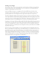
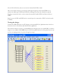
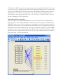
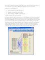
EMBEDDED SPACES INC. (ESI)
ESI
Technical Documentation
Shift Light & Rev Limiter
Application Note
This appnote covers:
•
•
•
•
•
•
Starting a new design
Testing the design
Upgrading the functionality
Rev-limiter connections
Tachometer input connections
Disclaimer
This is the most-basic appnote, intended to get you started, but it will get us to a useful
application in the end.
Starting a new design.
This is unusual. There is always some sample that’s worth renaming and editing, but just pull down
File>New and you have a new, untitled design. File>SaveAs will get you to the standard Windows
dialogue to name and place your new .pox file.
In this case RPMs are the guts of our application. We click the RPM object (looks like a little
Tachometer) from the toolbar and place it on the left side of the clean worksheet. There’s some
personal prejudice here. I do all design from left-to-right and the objects are set up that way.
The object configuration window opens up and we’re going to set up for your engine type. Click on
the v beside Cylinders and then Strokes, picking the appropriate entries. We’re going to start with 6
steps and I’ve chosen 6 cylinders and 4-strokes which give us 3 pulses per revolution. If you have an
unusual ignition system or use the RPM pulse out of an ECU, set the Pulses per Rev directly.
I’m going to set the steps to 6500 (my redline), 6000, 5500, 5000, 4500 and 4000. Type them into the
bottom 6 boxes, any order, they’re self-sorting. I’m also going to enable the simulate field at the top
so I can see something before I connect to an ignition system. Close the configuration window by
clicking OK. Should you accidentally close the configuration window, just double-click on the RPM
object and it will re-open.
Now we’re going to need some LEDs. Let’s set it up with Star-Trek converging lights and use the
Red one in the middle for the Shift indicator. The LED numbering is as you look at the front of the
powerONE from left to right. Click the LED object on the toolbar (looks like 3 yellow and 1 red
blobs) and start dropping them by clicking on the design, to the right, as you like. Each will open a
small configuration window. The only thing you need to do now is choose the LED and click OK
(but you can name them too if you like). It will keep dropping them until it runs out of LEDs or
until you hit the Esc key at the upper left of your keyboard.
Now it all looks like this, and you can see that I named the LEDs in mine.
OK, to have them sweep in, we want the outside pair to light up at the lowest RPM. So, we
connect the 4000 step to LED0 and LED10 by clicking the connect box beside the step and
dragging a connection from it to the connect box marked l beside LED10 and then another to
LED0.
Step 2 is next to LED1 and LED9 and so on until step 6 is connected to LED5. And we’re ready
to rumble.
Testing the design
Connect the USB cable from your PC/laptop to the powerONE (the Quickstart sheet in the box
showed you how to do all this) and download the application.
That simulate function just does a pretend RPM input ramping from 0 to 10,000 RPM, so with the
range we cover (4000 to 6500 RPM) they’re off for a long time and on for a long time, but you can
see the converging pattern as it passes through our range.
We’ll tighten the RPM range later, but what you have now is a serviceable shift light. At this point
you can give it a try by connecting the GND, BATT, GND and TACH inputs to your vehicle and
starting it up. GND and BATT are the power source and GND and TACH are usually from the
ignition primary or the ECU. You don’t need to loop the primary wire through here, it’s just a
voltage input so these can be connected to the + and – at the coil, for instance. There’s a note at
the end on making the TACH connection.
Upgrading the functionality
OK – we’ve given it a try and the RPM band is too wide. We just want to know when a shift is
coming up, not to have another tachometer to watch. Also, we’re not sure if we’ll notice the red
LED when things get busy. Well, let’s tighten the range, blink the red LED and also blink all the
LEDS if we start to over-rev. We double-click on each LED to open its configuration and set the
blink period to 250. That’s milliseconds, so they’re going to blink at 4 Hz. We also open the RPM
configuration, add one more step and update the steps to 5500, 5700, 5900, 6300, 6500 and 6600.
Then we move the connection from step 6 to the “b” input on LED5 and connect the b inputs of
all the rest to step 7. Now it looks like this.
We can have a quick look with simulate enabled, but it’s pretty obnoxious when you turn the key on,
so you may want to go back into the RPM object and disable it. You can see that I did.
Now we have a useful shiftlight that
•
•
•
Sweeps toward the centre with increasing revs
Blinks the centre red LED at the shift point
Blinks everything at 100 RPM over the shift point
Let’s drive it around a bit to see how we like it…….
OK, that was pretty nice, but we still tend to over-rev when things get busy and we’re guessing when
the red led is going to flash. When we just react to it we’re already over-revved. So, let’s move the
steps down 200 RPM and set up a rev-limiter. We’ll add step 8 at 6600 RPM. We’ll also add a USER
line as our rev-limit output and one more LED that will go on when rev-limiting. You can handle
the LED by yourself, but to get the USER line, click the USER icon and then click on the design to
place it. In the configuration I took User7; named it, set its Direction to Output and Function
(appears magically by context) to Control. Remember, you have to press Esc to stop it from dropping more
USER objects. Then we connect Step 8 to the LED11 l input and to the USER7 l input.
Now we have
•
•
•
•
LEDs sweeping in
SHIFT LED blinking at 6300 RPM
(200 below redline to allow reaction time)
Everything blinking at 6500 RPM
(wakeup reminder)
Rev Limiter coming in at 6600 RPM.
Rev limiter connections.
If your vehicle has an ECU, it probably has a shutdown or limit input. To use this you need to know
what the input level and polarity is; from your manual, or more likely on the web from the interestgroup for your vehicle. There are chat groups and interest pages for everything down to lawnmowers. No kidding! Anyhow the input will be +5V or +12V and it will go high-to-low or low-tohigh to shut down.
The output of the powerONE is the normal automotive type called a pull-down and you need to do
3 things here.
1. The input on the ECU needs to be pulled up with a resistor to the specified level. There is a
good chance that it has an internal pull-up, but find out.
2. Connect ground from the ECU to the GND input next to the USER connection.
3. You need to set the Output Active in the USER object to High or Low, whichever way the
ECU shuts down
If the ECU isn’t there for you, you’ll need a relay. A standard automotive relay is fine and you’ll
want to use the NC (normally closed) connection. Connect one side of the relay coil (85) to +12 and
the other side to the USER connection. Connect ground from the chassis to the GND input next to
the USER connection. We’ll set the output to Low-Active in this case and when the powerONE
sets the USER output, it will go low, energizing the relay and opening the NC connection. We’ll
connect whatever it is we’re going to stop across (30 and 87a) the NC terminals.
Now you need something to interrupt.
1. First choice is to cut power to the fuel injector or injectors (not to the EFI controller). You
need to get into the schematic in the service manual to locate this point, but it should be
there and it works really well. The engine just dies until the revs go below the set limit. If you
hold it there it will make that babbling sound called “bouncing off the limiter”.
2. Second-best is cutting power to the ignition primary. It’s second-best because fuel
accumulates while the ignition is off, so it makes all kind of banging and farting when it
comes back on. Better than detonating the engine with an over-rev though. For this one you
just put the relay in a convenient place and run the ignition primary through the NC
connection.
3. In all cases, you should use the NC connection so that it runs if you don’t have the
powerONE installed, or powered on or break a connection or whatever
The speed of the relay and the sensitivity setting in the RPM object determine how much overshoot
the limiter will have and what the RPM spread will be when you are bouncing off the limiter. The
sensitivity setting is straightforward. With my setting of 10, RPMs will go to 6610 before it activates
the USER output. You don’t really want to set the sensitivity too fine because you don’t want the
steps to go switching on and off at a crazy rate when you’re right at the RPM setting. The delay will
be 2.5 to 5 milliseconds so you can pretty well ignore it.
The relay is more interesting. Its delay will likely be 15 or 20 milliseconds and if you have a low gear,
big power and little weight, the revs may be climbing at 2000 RPM/second and 15 ms will be 30
RPM. You can spend more money on a faster type of relay, such as a solid-state relay, or just move
the limit down a bit. Moving the limit down has some disadvantage in the higher gears, where you
may be climbing at 200 RPM/second and you’ll have moved the limit down into your safe powerband.
Tachometer input connections.
The TACH input will count pretty-well anything.
1. An ECU output. This will be a 1 pulse-per-rev signal intended for another system or for a
tachometer. It will signal positive or negative- going at +12 or +5 volts. It doesn’t matter; a
powerONE will figure it out by itself so long as you tell it 1 pulse per rev in the RPM object
setup.
2. We already mentioned the ignition primary.”You don’t need to loop the primary wire through here,
it’s just a voltage input so these can be connected to the + and – at the coil, for instance“. You need to set
the cylinders and 2 or 4-stroke in the RPM object setup.
3. In either case the signal needs to be monotonic. This means that a pulse rises and falls
cleanly, without bouncing around the midpoint. If it does cross the midpoint multiple times
the powerONE will happily count each one of them, and you’ll see a multiple of the true
reading. In this case you need add a filter, so you probably need help from someone with an
oscilloscope. The filter will look like a series resistor in the line and a capacitor between the
powerONE side of the resistor and the GND input. Typical values might be 1K ohm and
0.1 uF, but you need to see the waveform to know that it’s nicely settled down.
Disclaimer.
Any of the rev-limiter connection require a good working-knowledge of what is safe for your engine.
If you don’t have that knowledge, get a recommendation from a professional auto-tech before you
start, or have the tech do the installation. The tachometer connection won’t do worse than disable
your tachometer, but professional advice there isn’t a bad idea anyway.