1
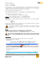
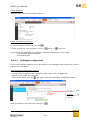
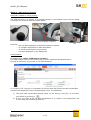
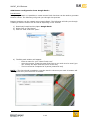
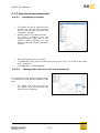
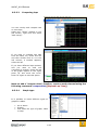
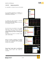
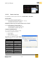
2013 USER MANUAL
G. SOFTWARES / DATAS
ACQUISITION
98CUP_2013 Release
G SOFTWARES / DATAS ACQUISITION
CONTENTS
G
SOFTWARES / DATAS ACQUISITION
G.1 DATAS ACQUISITION
G.1.1 PRESENTATION
G.1.2 DATALOGGER
G.1.3 COMMUNICATION
G.2 TOOLSET
G.2.1 DATAS DOWNLOADING
G.2.2 LIVE PARAMETERS MONITORING
G.2.3 DASHBOARD CONFIGURATION
G.2.3.1 QUALIFYING MODE (QM)
G.2.3.2 SEND A CIRCUIT MAP
G.2.3.3 ICD SETUP
G.2.3.4 SHIFTLIGHTS CONFIGURATION
G.2.3.5 BEACON CONFIGURATION
G.3 DATA ACQUISITION CHANNEL LIST
G.4 DATA ANALYSIS / TOOLBOX
G.4.1 CONFIGURATION VIA SOFTWARE
G.4.2 OPENING DATAS
G.4.3 ANALYZING DOWNLOADED DATA
G.4.3.1 DISPLAYING A CHANNEL
G.4.3.2 CHANGING THE REFERENCE AXIS (TIME/DISTANCE)
G.4.3.3 COMPARING LAPS
G.4.3.4 GRAPH TYPE
G.4.3.5 GRAPH PROPERTIES
G.4.3.6 CREATE A TRACK MAP
G.4.3.7 CREATE A XXX.QM FILE
G.4.3.8 TRAJECTORY COMPARISON
G.4.4 SHORTCUT KEYS
C-2
2
3
3
3
3
6
6
8
9
9
11
12
13
14
18
23
23
23
24
24
24
25
25
26
27
30
31
33
98CUP_2013 Release
G.1 DATAS ACQUISITION
G.1.1 PRESENTATION
The vehicle is supplied with an USB Stick containing the following software applications:
-
TOOLSET v3.x
o Check live parameters (engine, Gearbox, chassis…etc)
o Downloading datas recorded in the datalogger
o Configure your dashboard
-
TOOLBOX 6.2
o Data acquisition analysis
All these softwares are compatible with Windows XP, Vista and 7.0
G.1.2 DATALOGGER
The data logger is integrated in the
dashboard.
The logger’s memory is 1 Gb.
Its operational temperature range is 10°C
to 60°C.
Weight : 750g
The dashboard is plugged to the chassis
loom (C4)
G.1.3 COMMUNICATION
The communication between the computer and the dashboard is made by ETHERNET
Protocol (TCP/IP) using a Network card.
Communication Wire (8201 414 870)
Ethernet cable / Category
5E
CANNON ITT
12 Pins
Computer
side
Dialog
connector
side
C-3
98CUP_2013 Release
Dialog connector:
The dialog connector (Chassis loom C15) is fitted instead
of the original right aerator.
Network configuration / IP Address :
You first have to enter the correct IP Address
To do so, go to “Network Connections” :
“Start” menu
“Parameters”
“Network Connections”
Then make a right click on the good “local network” to choose “properties”
With Windows XP, select “internet protocol TCP/IP” and click on “properties”
NOTE : for Windows Vista & 7.0 choose “internet protocol” and “TCP/IP v4”
Fill the corresponding areas as below:
IP ADDRESS : 172.16.255.124
SUBNET MASK : 255.255.0.0
When everything is completed as described above, click on “OK”
C-4
98CUP_2013 Release
Communication Speed :
It may be necessary to reset your PC communication speed to “Automatic”, following the
instructions below:
Click on “Start” menu
“Parameters”
“Network Connections”
Right click on “local network” to choose “properties”
Click on “configure” and choose the tag “advanced”
Select « speed and duplex » line and choose « auto negotiation »
NOTE :
Depending on the Windows version, this line can be named differently. The most
important thing is to choose the one which mentions the communication speed.
C-5
98CUP_2013 Release
G.2 TOOLSET
Toolset software will allow you to:
-
Check live parameters (engine, Gearbox, chassis…etc)
Download datas recorded in the datalogger
Configure your dashboard (shiftlights, qualifying mode, beacons,…etc)
Make and send the datas acquisition setup
G.2.1 DATAS DOWNLOADING
Install and then open the software
Toolset 3.x on your computer.
By default, the installation software
proposes
you
the
following
destination:
C:\Program files\Pi Toolset
Reminder : Change the computer
IP address to connect to the car:
IP address:
172.16.255.138
Subway Mask: 255.255.0.0
Offload Path configuration :
On the top menu,
Go to “Settings” / “Data Offload”
Then you can choose the :
“root path”
“relative path”
The root path is combined with the
Relative Path to form the complete
path
and
filename
of
the
downloaded file (xxx.pds).
By clicking on
you can modify
all of these parameters. It’s
possible to include the exact date,
the session, the driver name,…etc
The “Preview” indicates :
The
name
of
the
downloaded file
where the file will be
saved
Offload Conditions :
We also recommend you to
configure
the
general
offload
settings as indicated above.
Don’t forget to “Save” after
every modification
C-6
98CUP_2013 Release
Devices :
When you connect to a new
dashboard system for the first time,
you have to add and save this
system :
On the top menu,
Go to “Devices”
Click on
to add a device : the
following windows appears and
indicate the ICD-Lite-RST serial
number (same number written on
the back of the dash)
Select it and click on
The ICD is now saved and will be
automatically detected every time
you will connect to it.
You can saved as many ICD as you
want in your Toolset configuration
To select the ICD you want to
communicate with, it is necessary
to click on
A “tick” appears near the ICD
selected
NOTE : on, the right column, it is
possible to change the ID, the
name and to add comment for this
dashboard
Data downloading :
On the top menu, Go to “Data”
You first have to fill the settings of
the outing you want to down load:
1) Click on the data file you want to
download (DO NOT click on the
arrow pointed to the bottom to
avoid automatic offload)
2) The right column appears,
displaying the outing number, the
date and the Run time. We
recommend you to fill the track
name, driver name, car name, and
to add short and long comment if
you want
NOTE : Filling this area will allow
you to save the downloaded file
following the offload path defined
on previous page
3) Click on the arrow pointing to
the bottom to start downloading
Select an Outing to start the
downloading
The corresponding outing is saved
to the path chosen previously.
1) Click here
2) Fill this area
3) Click on the arrow
to offload
datas offloading in
progress
C-7
Datas offloaded
98CUP_2013 Release
G.2.2 LIVE PARAMETERS MONITORING
There is not standard “live datas”
configuration. You have to make it by
yourself.
On the top menu, Go to “Live Data”
List of pages :
You can add as many pages as you want
by clicking on
A list of blank pages will appear on the
left column.
You can rename the pages as you want
: ENGINE, GEARBOX…etc by clicking on
the name area
It is possible to remove a page by
clicking on
Pages configuration :
On each pages, you can now add the
channels you want for live monitoring :
Add a column by clicking on
Then click on
to display the list of
available channels and choose the
desired channel(s)
See the channel list on § G.3
You can choose between 2 types of
display :
•
Standard
•
Compact
C-8
98CUP_2013 Release
G.2.3 DASHBOARD CONFIGURATION
Toolset also allows you to configure the following parameters:
-
Shift lights thresholds
Beacon type configuration (single beacon receiver or GPS receiver)
Qualifying mode configuration
Circuit map
G.2.3.1
Qualifying mode (QM)
The Qualifying Mode allows drivers to compare in live their current lap to a reference lap
according sectors defined in Toolset.
Qualifying mode access :
Connect your computer to the right ICD (check that a “tick” is displayed)
On the top Menu, go to “Action” and then click on
to open the qualifying mode :
Qualifying mode configuration :
3 modes are available and are listed below:
MODE 1 = AUTOMATIC MODE
Distance based : Autolearn
The ICD will automatically learns the track
length and then split the lap into a number
of segments
The reference lap can be learnt as :
- The fastest lap
- An addition of all best segments
It is possible to define from 2 to 128
segments
The track is divided in equal length portions
depending on the number of segments
chosen. For example, if 10 is chosen and
the track length is 5,000m, the driver will
observe on the dashboard a new split every
500m.
NOTE : by default, this mode is enable with the following
configuration :
- Fastest lap learned
- 128 segments
When the configuration is achieved, click on
C-9
98CUP_2013 Release
MODE 2= SEMI-AUTO MODE
Distance based : PDS File
reference
A xxx.pds file (downloaded file, see G.2.1)
is selected as the reference lap (from the
connected ICD or another one)
This reference lap is used to determine the
track length and the track is automatically
split into segments.
Click on
to browse your computer and
load the outing (.pds file)
The “file properties” displays the main
information of this outing (driver, track
name, date…etc)
“datum lap” indicates the reference lap time
selected. By default the best lap of the
outing is chosen.
The reference lap can be learnt :
- As it was created (init segment times)
- As the fastest lap
- As an addition of all best segments
It is possible to define from 2 to 128
segments (as for MODE 1).
When the configuration is achieved, click on
MODE 3 = MANUAL MODE
Distance based : QM File
generation
A xxx.qm file is created using a xxx.pds file
in the TOOLBOX software (see G.4 Datas
analysis)
The user :
- Loads a xxx.pds file on TOOLBOX
- Defines the segments exactly where he
wants
- Exports file and saves it as a xxx.qm
- This xxx.qm file is used in Toolset
qualifying mode
Segments
generated in
TOOLBOX
from a .pds
file
This reference lap is used to determine the
track length and the positioning of the
defined segments
Click on
to browse you computer and
load the outing (.qm file)
The “file properties” displays the main
information of this outing (driver, track
name, date…etc)
“datum lap” reminds the reference lap time
selected
The reference lap can be learnt as for MODE
2:
When the configuration is achieved, click on
C-10
98CUP_2013 Release
Corresponding dashboard page :
The Qualifying mode is visible by the driver on “driver page” n°2 (refer to chapter BPresentation)
+ / - : comparison with the reference lap selected after each segment
Bargraph : 1 bar = 1 tenth (ahead or late)
Split time: stay displayed 5 sec after the end of the segment
NOTE :
Depending on segment number defined, the split time remains displayed +/- long time
When 128 segments are defined, we can consider that it’s a “live update”
G.2.3.2
Send a Circuit Map
This function allows loading a circuit map (xxx.bmp file) on “driver page” n°3 (refer to
chapter B-Presentation)
Circuit Map change:
- Connect your computer to the right ICD (check that a “tick” is displayed)
- On the top Menu, go to “Action” and then click on
Refresh
configuration
to open the “send image” mode:
the
by
clicking on
- Make a double
Click on the circuit
map (a browser
opens)
- chose a
(.bmp file)
circuit
- the selected circuit appears on this page to confirm that it has correctly been uploaded
NOTE : The circuits can be available form Renault Sport Extranet or created by the user.
C-11
98CUP_2013 Release
G.2.3.3
ICD SETUP
The configuration of many information displayed or accessible through the ICD (as for
example a part of the data acquisition channels list, the CAN decode…etc) is managed by
a “SETUP” which has to be sent to the dash after every update.
Each SETUP is named as described below:
<Year> Clio CUP Base setup <Version> - <Tyre diameter> <Tyre manufacturer>.toolset
2 base setups will be available in the future
2 tyres manufacturers = 2 different tyre diameters
Setup 1 : 2013 Clio CUP Base Setup Vx.x – 610 MICHELIN.toolset
Setup 2 : 2013 Clio CUP Base Setup Vx.x – 620 DUNLOP.toolset
Both 2 setups are strictly identical except the 3 speed channels of the data acquisition
channel list:
o Speed_FL
o Speed_FR
o Speed
Indeed, as the MICHELIN and the DUNLOP Tyre have a different diameter, the Speed
(displayed and logged) is calculated differently.
After every tyre change, we strongly recommend you to load the right setup
(corresponding to the tyre used) in the ICD to avoid confusion on Speed
calculation
NOTE :
- By Default, every brand new ICD is delivered with a MICHELIN Setup
- As 2013 season will exclusively use MICHELIN tyre, only the setup
2013 Clio CUP Base Setup Vx.x – 610 MICHELIN.toolset will be available
The last Setup version will always be available on the Renault Sport
Extranet / area SOFTWARES. Don’t forget to download the last version
regularly
Setup access :
- Connect your computer to the right ICD (check that a “tick” is displayed)
- On the top Menu, click on ‘SETUP”
- It is possible to :
-
Import a setup : click on
-
Read a setup from the active device : click on
. Browse you computer and load it
C-12
98CUP_2013 Release
Setup opening :
Make a double click on the Setup to open it
Setup uploading and saving :
To send a setup to the device, click on
To save a setup on your computer, click on
(save) or
(save as)
The user has the possibility to configure 2 important parameters in the setup :
- The Shiftlight LEDS thresholds
- The beacon type
G.2.3.4
Shiftlights configuration
This function allows configuring the thresholds of the shiftlights LEDs lighting up (refer to
chapter B-Presentation)
Shiftlight LEDs configuration access :
- Connect your computer to the right ICD (check that a “tick” is displayed)
- Open a setup (check the tyre type)
- In the Home Menu, click on
to open the shift lights configuration mode :
Set the 8
thresholds
Configuration
by default
Send the setup to the device by clicking on
C-13
LEDS
Reminder:
the
Engine limiter is
6,500rpm
98CUP_2013 Release
G.2.3.5
Beacon configuration
This function allows configuring the beacon mode.
Beacon configuration access :
- Connect your computer to the right ICD (check that a “tick” is displayed)
- Open a setup (check the tyre type)
- In the Home Menu, click on
to open the beacons configuration mode:
2 main modes available:
MODE 1: classic beacon receiver
Reminder (chapter F-wiring looms):
The Lap beacon is fitted on rear left or rear right roll cage tube and must be visible
through door window.
It allows:
- the Lap decomposition in the data acquisition system
- Lap time displayed on the dashboard
CHASSIS LOOM
C21
To “cut” the laps using the lap beacon, the presence of the corresponding
COSWORTH track wall beacon (7711166112) is required:
Configuration:
In Beacon type, select “10 -channel beacon receiver”
During every Race meeting, only the standard beacon receiver (as
indicated above) must be selected. The track beacon is fitted by the
Renault Sport championship organizer.
C-14
98CUP_2013 Release
MODE 2 : GPS beacon receiver
Reminder (chapter F-wiring looms):
The GPS Receiver is an option. It is plugged directly on the chassis loom near the dialog
connector and must be fitted as shown below:
GPS receiver fitting (magnetic)
It Allows:
-
CHASSIS LOOM
C20
the Lap decomposition in the data acquisition system
to compare trajectories in data acquisition
to avoid a track beacon requirement
Lap time displayed on the dashboard
Configuration :
In Beacon type, select “GPS beacon receiver”
The GPS beacon must not be used during an event organized by Renault Sport.
It must be used only for private or non official testing.
To correctly “cut” the lap, it is necessary to fill the start and finish lines GPS coordinates
(latitude and longitude) of the corresponding circuit. 2 possibilities:
1) The track GPS coordinates already exists on the library (.kml file), in this case,
just load it by clicking on
2) If not, you have to fill the GPS coordinates or to create a new start/finish line
circuit using the following procedure :
C-15
98CUP_2013 Release
GPS Beacon configuration from Google Earth :
Introduction:
Using Google earth it is possible to create a start finish line that can be used to generate
beacon events. The following will guide you through this process.
Beacon locations can be created using Google Earth. The following will talk you through
creating a beacon location file as well as importing it into Toolset:
1) Download, Install and the Open Google Earth
2) Right Click on “My Places”
3) Click on “add” and then “path”
4) The Edit path window will appear
- Enter a name for your "Start Finish Line"
- Using the mouse, draw the start finish line as you wish it to be used (you
can modify the style and the colour of the line)
- The line must be composed of 2 points (start and end)
NOTE : This line should completely cross the track in the area you need. A beacon will
be triggered every time this line is crossed.
C-16
98CUP_2013 Release
5) You can add multiple "Start Finish" lines to a single file if the circuit in question
has got multiple lines
6) Once you have created your "Start Finish" line you will need to export it:
- Right click on the path and click on “Save Place As…”
7) It is important that you select the *.kml file format that is available with the drop
down box
8) Once you have created you "Start Finish" .kml file, it can be imported into Toolset
using the Beacons configuration (see page C.15) by clicking on
9) Once you have added the track you will be able to select the Beacon, if you have
added multiple paths to a single .kml you will be able to select the one you want
from the drop down menu.
NOTE :
Even if the GPS is not selected as beacon, the GPS coordinates (latitude, longitude,
speed, altitude) are still logged in the ICD and allow the Map drawing and trajectory
comparison in TOOLBOX software (see G.4 data analysis)
During every Race meeting, only the standard beacon receiver (as
indicated above) must be selected. Configuring the GPS as a beacon is
strictly forbidden.
C-17
98CUP_2013 Release
G.3 DATA ACQUISITION CHANNEL LIST
The following table presents the complete channel list logged in the ICD.
“Bit indicator column” indicate if this channel can be considered as a Bit field in
TOOLBOX.
To facilitate the understanding, except classic channels (brake pressure, accel X and Y,
distance, speed…etc), all channels are grouped behind a family name :
Dash_ (Cosworth ICD LITE)
ECU_ (Cosworth SQ7Di)
EN_ (Engine)
CBNT_ (XAP CBNT)
GB_ (gearbox)
QM_ (qualifying mode)
GPS_
ICD Channel name
Signification
Accel_X
Longitudinal acceleration
Accel_Y
Lateral acceleration
Accel_Z
Vertical acceleration
Battery Voltage
Battery voltage
Brake_Balance
Brake balance (% front)
Brake_Press_F
Front brake pressure
Brake_Press_F Offset
Front brake pressure offset
(must be 0 after a reset procedure)
Brake_Press_R
Rear brake pressure
Brake_Press_R Offset
Rear Front brake pressure offset
(must be 0 after a reset procedure)
CBNT_CMD_Rain Light_Omega
Rain light command sent by CBNT
CBNT Check 1_Omega
CBNT Diagnostic / Always = 0xAA (dec = 170)
CBNT Check 2_Omega
CBNT Diagnostic / Always = 0x55 (dec = 85)
CBNT_SWT_State
CBNT_PCM_Diag_1
CBNT_PCM_Diag_2
CBNT_PCM_Diag_3
CBNT_PCM_Diag_4
CBNT switches state (ON or OFF)
Pin_H_Stop light switch
Pin_G_ Rain light switch
Pin_B_Light left switch (Front and rear)
Pin_A_light right switch (Front and rear)
CBNT status (Ok or fault)
Pin_N_ Wheelspeed
Pin_M_XAP gearbox actuator
Pin_L_+12v output
CBNT status (Ok or fault)
Pin_T_dash
Pin_D_VVT
Pin_C_HP pump/waste gate/ pop off
Pin_J_ECU
Pin_ K_steering wheel
Pin_F_ starter excitation
Pin_E_geabox barrel unlocking
CBNT status (Ok or fault)
Pin_H_Stop light
Pin_G_rain light
Pin_B_Light left switch (Front and rear)
Pin_A_light right switch (Front and rear)
CBNT status (Ok or fault)
Pin_h_g_ignition coil
Pin_V_W_low P fuel pump / lambda sensor
Pin_R_P_Wiper
Pin_f_winscreeen washer
C-18
Bit
indicator**
YES
YES
YES
YES
YES
98CUP_2013 Release
Dash_Alarm_EN_Air_Temp
CBNT state (ON or OFF)
Pin_Z_brake light cmd
Pin_e_rain light cmd
Pin_j_light cmd
Pin_S_wiper at ref position
Pin_Y_ignition
Pin_U_low press fuel pump cmd
Pin_X : not used
Pin b_c_CAN2
CBNT state (ON or OFF)
Pin_N_ Wheelspeed
Pin_M_XAP gearbox actuator
Pin_L_+12v output
CBNT state (ON or OFF)
Pin_T_dash
Pin_D_VVT
Pin_C_HP pump/waste gate/ pop off
Pin_J_ECU power
Pin_ K_steering wheel
Pin_F_ starter excitation
Pin_E_gearbox barrel unlocking
Battery alarm displayed on ICD
Air temp alarm displayed on ICD
Dash_Alarm_EN_High_Fuel_Press
High Press fuel alarm displayed on ICD
Dash_Alarm_EN_Low_Fuel_Press
Low press fuel alarm displayed on ICD
Dash_Alarm_EN_Oil_Press
Engine Oil press alarm displayed on ICD
Dash_Alarm_EN_Water_Temp
Water temp alarm displayed on ICD
Dash_Box_Temp
Dashboard temperature
Dash_Error_EN_Boost_Press
Boost P sensor error message displayed on ICD
Dash_Error_EN_High_Fuel
HP fuel sensor error message displayed on ICD
Dash_Error_EN_Low_Fuel
LP fuel sensor error message displayed on ICD
Dash_Error_EN_Man_Press_Air_T
Manifold P sensor error message displayed on ICD
Dash_Error_EN_Oil_Press
Oil P sensor error message displayed on ICD
Dash_Error_EN_Pedal
Gas pedal potentiometer error message displayed on ICD
Dash_Error_EN_Throttle
Throttle position sensor error message displayed on ICD
Dash_Error_EN_VVT1
VVT position sensor error message displayed on ICD
Dash_Error_EN_Water_Temp
Water T sensor error message displayed on ICD
Dash_Error_GB_Actuator
Gearbox XAP actuator error message displayed on ICD
Dash_Error_GB_Barrel
Gearbox barrel error message displayed on ICD
Dash_Error_SW_Down_Paddle
Down paddle error message displayed on ICD
Dash_Error_GB_R_Solenoid
GB barrel sensor error message displayed on ICD
Dash_Error_GB_Up_Cont
GB upshift sensor error message displayed on ICD
Dash_Error_SW_Up_Paddle
Up paddle error message displayed on ICD
Dash_Error_Speed
Speed sensor error message displayed on ICD
Dash_Error_Steering
Steering angle sensor error message displayed on ICD
Dash_Free_CPU
ICD Free CPU
Dash_Inp_1_Volt
ICD input 1 voltage (rear brake press sensor)
Dash_Inp_2_Volt
ICD input 2 voltage (front brake press sensor)
Dash_Inp_3_Volt
ICD input 3 voltage (fuel level sensor)
Dash_Log_Mem_Rem
ICD logging memory remaining
Dash_Log_Status
ICD logging status (OK / fault)
Dash_Log_Time_Rem
ICD logging time remaining
CBNT_PCM_Diag_5
CBNT_PER1A_STATE
CBNT_PER5A_STATE
Dash_Alarm_Battery Voltage
C-19
YES
YES
YES
98CUP_2013 Release
Dash_Logging
ICD logging state (Yes / no)
Dash_Serial_Number
ICD serial number
Distance
Distance calculated from the beginning of the RUN by ICD
ECU_Alarms
Alarm min/max recorded (Yes/No)
Water T, OilP, batt V, air temp, fuel Hp, fuel LP
YES
ECU_Autocal_Code_States
PPS (pedal) / TPS (Throttle) calibration state
YES
ECU_Battery Voltage
ECU battery voltage
ECU_serial number
ECU serial number
ECU_distance
ECU_Ouputs_States
Distance calculated from the beginning of the RUN by ECU
calculated with MICHELIN 610 tyres
(=”Distance” channel when a MICHELIN 610 setup is load
ECU output states (ON/OFF)
LP_Fuel_pump
Slow speed water fan
High speed water fan
YES
ECU_Switch_States
ECU switch states (ON/OFF)
Pit lane Switch
Gear switch
Up_contactor switch
Up_paddle switch
Down paddle switch
YES
ECU_Throttle_FBW_Status
Fly by Wire (Gas Pedal/Throttle) status (OK/fault)
FBW, Pedal, Throttle A and B, diff check, noise check
YES
EN_Air_Temp
Air temperature sensor value
EN_Baro_Press
Barometric pressure value (learn before engine start)
EN_Boost_Press
Boost pressure sensor value
EN_Engine_Error
EN_Engine_Error_2
Engine sensor error (part 1)
Water T, throttle, oilP, crank, airT, Baro P, manifold P,
crank and camshaft signal, pit lane ctrl, HP fuel, WSP,
injectors
Engine sensor error (part 2)
Pedal, boostP, VVT, steering, gear pot, upshift cont, LP
fuel…etc
YES
YES
EN_Engine_Mode
Engine status ; RUN, SYNC 360, SYNC 720…etc
YES
EN_Engine_Status
Engine status
Rev_limiter, rev_cut, pit_lane_cruise, sync …etc
YES
EN_High_Fuel_Press
High Fuel pressure sensor value
EN_HP_fuel_pump _tgt
High Fuel pressure sensor value
EN_Inj_Time
Injection time (ms)
EN_Low_Fuel_Press
Low Fuel pressure sensor value
EN_Manifold_Press
Manifold pressure sensor value
EN_Map
Map selected on facia switch panel (0 : DRY / 1 : WET)
EN_Oil_Press
Oil pressure sensor value
EN_Pop_Off_Pos
Pop off valve position
EN_Pop_Off_tgt
Pop off valve position target
EN_RPM
Engine RPM (TDC sensor value)
EN_VVT_Status
inlet Cam status : VVT_pos/VVT_tgt (OK/fault)
EN_VVT1_Pos
Intake camshaft position (real position of intake camshaft)
EN_VVT1_Tgt
Intake camshaft target value (send by ECU to dephaser)
EN_Water_Fan_State
Water fan state 0: OFF / 1 : low speed / 2 : High speed
EN_Turbo_Water_Fan_State
Turbo air exchanger fan state : O:OFF / 1:ON
EN_Water_Temp
Water temp sensor value
C-20
YES
98CUP_2013 Release
EPS_warning status
Electric power steering warning status
Fuel_Level
Fuel cell level
Fuel_Used
Fuel used since the begging of the Run
GB_actuator_cmd_diag
XAP Gearbox actuator command diagnostic
Cmd 21v (UP/DN), Cmd 14v (UP/DN), Cmd 14v return
GB_actuator_out_current
XAP Gearbox actuator out current (Amps)
GB_actuator_sensor_1
XAP Gearbox actuator sensor 1 state
GB_actuator_sensor_2
XAP Gearbox actuator sensor 2 state
GB_actuator_state
XAP Gearbox actuator state
Return UP/DN, ready, active, idle, return
GB_actuator_volt
XAP Gearbox actuator voltage
GB_down_cmd
ECU downshift cmd to XAP Gearbox actuator
GB_high_power_cmd
ECU shifting high power cmd to XAP Gearbox actuator
GB_low_power_cmd
ECU shifting low power cmd to XAP Gearbox actuator
GB_up_cmd
ECU upshift cmd to XAP Gearbox actuator
GB_Up_Cont_State
Gearbox upshift contactor state (0/1)
GB_Voltage
Gearbox barrel potentiometer voltage
Gear
Gear ratio engaged
Global alarm
Global alarm
GPS_Alt
GPS altitude signal
GPS_Lat
GPS latitude signal
GPS_Long
GPS longitude signal
GPS_Sats
GPS satellites detected
GPS_Speed
GPS speed
Lap Distance
Lap distance
Lap Number
Lap number
Lap Time
Current Lap time
Lap_Beacon
Lap beacon signal cut
(becomes 0 when track beacon is detected)
Logging
ICD logging (YES/NO)
Mileage
Total car mileage calculated by ICD
Outing Number
Outing number
Outing Time
Outing time
Pedal
Gas pedal potentiometer value
Pedal_1_raw
Gas pedal potentiometer raw 1 voltage
Pedal_1_raw
Gas pedal potentiometer raw 2 voltage
Previous lap time
Previous lap time recorded
QM Cum Seg Time
Qualifying mode cumulative segment time
QM Cum Seg Time Diff
QM Seg Time Diff
YES
YES
YES
Qualifying mode cumulative segment time difference
compared to the reference lap
Qualifying mode segment time difference compared to the
reference lap
QM Segment Number
Qualifying mode segment number
QM Segment Time
Qualifying mode segment time
QM Status
Qualifying mode status
QM predicted lap time
Qualifying mode predicted lap time
QM reference lap time
Qualifying mode reference lap time
C-21
98CUP_2013 Release
Reset_Button
Reset button pressed on facia switch
Reset_Cmd
Reset command (managed by the ICD)
Reset_Response
Reset command response (ECU)
Dash_Shift_Lights
Dash RPM LEDs lighting up (1 to 8)
Speed
Average speed (FL and FR)
Speed_FL
Front left wheel speed value
Speed _FR
Front right wheel speed value
Steering_Angle
Steering angle sensor value
SW_Down_Paddle
Down paddle pulled
SW_Switch_States
Steering wheel button panel state (ON/OFF)
Wiper/pit/clean/page/light/gear/free
SW_Up_Paddle
Up paddle pulled
SW_page
Steering wheel “page” button pressed
Throttle_1_Raw
Throttle potentiometer : track 1 tension
Throttle_2_Raw
Throttle potentiometer : track 2 tension
Throttle
Throttle potentiometer position
Tyre_diameter
Tire diameter selected (depends on setup sent to the ICD)
Steering_Status
Steering status
Steering_Speed
Steering speed
Total_Distance
Total car distance calculated in ECU (above 400rpm)
Tr_state
Gear control strategies steps
YES
YES
YES
NOTE 1 : In the datas downloaded, you will also see a list of channel with a name
starting by “Raw”. Theses channels are used for diagnostic and correspond to channels
coming through CAN from the ECU
For example, you will find the physical channel : “ECU_battery voltage” and its
corresponding “Raw” : Raw_ECU_Battery voltage
**NOTE 2 : Concerning the “bit indicator”
It is possible to change the configuration of the bit caption to observe directly its status
or its state. To make it, make a right click on the bit indicator and tick or not the last line
“show bit caption”
C-22
98CUP_2013 Release
DATA ANALYSIS / TOOLBOX
G.3.1 Configuration via software
The software used to analyse data acquisition is PI Toolbox.
Software installation
The Pi Toolbox software can be installed with the USB Stick provided by Renault Sport or
directly from the Renault Sport extranet
How to use the software?
Once this software is opened, select a workbook, then refer to the next paragraph to find
out how to open and analyse the data.
G.3.2 Opening datas
To open data:
• Open PI Toolbox,
• Select a workbook (.pwb)
NOTE :
If you want to create a new
workbook, go to Files -> New.
Select a default model of template,
then create your own workbook
from this one.
- You can also use the predefined
workbook available on the Renault
Sport Extranet:
“clio-cup-default.pwb”
Regarding the Toolset limited
access,
only
one
sheet
per
workbook can be used. But you can
use as many workbook as you
want.
•
•
Go to Data -> Add Outing
Select the run you want to
open (.pds file)
C-23
98CUP_2013 Release
G.3.3 Analyzing downloaded data
G.3.3.1
•
•
•
•
•
•
Displaying a channel
To display a channel, select the left
column and use the left and right
arrow in the bar until you reach the
“Selection” window
Double click on the channel name.
To remove a channel from the
graphic window, right click on the
channel name displayed on the
bottom of the left column and select
remove.
Several channels can be overlaid.
To ZOMM IN, press Ctrl and select the part of the curve you want at the same
time, or press Z.
To ZOOM OUT, use BACKSPACE.
G.3.3.2
Changing the reference axis (time/distance)
It is possible to change the reference axis:
you have the choice between distance and
time.
•
To change the axis, right click on
the graph, then select Axes and
select Time or Distance.
C-24
98CUP_2013 Release
G.3.3.3
Comparing laps
You can overlay and compare two
or more laps.
Select the “Tasks” window in the
left column, right click and select
“Add outing”.
If you want to compare two laps
from the same run, select this run
and then double click on it in the
left column; a window appears,
select the lap.
If you have different laps overlaid,
and you want to shift one
compared to another, select the lap
in the graph legend on the right,
press “O” and move the curve.
Press “O” again to exit this option.
Note: to add a “compare time” function, create a math channel using the
following command: compareDist([Elapsed Lap Time])
G.3.3.4
Graph type
It is possible to insert different types of
graphs or tables.
•
•
•
Go to Insert
Display
and select the type of graph, table
or map.
C-25
98CUP_2013 Release
G.3.3.5
Graph properties
It is possible to change the scale of the graph:
In the channel properties (in “Display”), if
Autoscale is selected (“yes”), the scale is
automatically calculated.
To choose the scale manually, Autoscale
should not be selected (‘No’).
Set up the scale using “Display minimum”
and “Display maximum”
You can move the position of the graph
along the Y axis: in “Y-axis % enabled”,
“yes” should be selected. Click on the left
column when the channel is selected, and
manually move the curve in the graphic
window.
This feature only works in “overlaid” mode
(refer underneath).
When you modify in “Display”, the change
is only in the selected graphic window,
whereas with “Workbook”, all the graphic
windows are modified.
The curves can be tiled or overlaid. To
change this, right click on the graphic
window, select “Axes” and “Tiled” or
“overlaid”
C-26
98CUP_2013 Release
G.3.3.6
Create a track map
It is possible to create 2 types of track map : standard MAP or GPS MAP :
Standard MAP :
Can be drawn thanks to the data logged by :
- The lateral acceleration sensor (channel : Accel_Y)
- The speed sensor (channel : Speed)
GPS MAP (possible only if the optional GPS receiver is fitted)
Can be drawn thanks to the data logged by :
- The GPS altitude (channel :GPS _Alt)
- The GPS longitude (channel :GPS _Long)
- The GPS latitude (channel :GPS _lat)
TOOLBOX CONFIGURATION:
For a correct MAP creation (standard or GPS),
it’s necessary to configure the channels
•
•
•
Go to “Tools”
Select “options”
Click on the tag “channels”
The purpose is to attribute for each common
name, the use of the real channel (logged
channel in the ICD)
Common name
Altitude
Corrected distance
Corrected Speed
Distance
Fuel used
Global time
Heading
Lap distance
Lateral acceleration
Latitude
Longitude
Map position D
Map position X
Map position Y
Map position Z
Speed
Real channel
GPS_Alt
Corrected distance
Corrected Speed
Distance
Fuel used
Global time
heading
Lap distance
Accel_Y
GPS_Lat
GPS_Long
Map position D
Map position X
Map position Y
Map position Z
Speed
C-27
98CUP_2013 Release
STANDARD MAP DRAWING :
To obtain the track map window :
• Go to “Insert”
• Select “Display”
• Click on “Map”
To draw the stardard Map:
•
•
•
•
Right click on the run (in “Tasks”
window)
select “Create Map”
click on “standard Map”
Use “Offset” and “Scale” to reproduce
the track map.
Note: to invert the track map, use a
negative scale factor.
C-28
98CUP_2013 Release
GPS MAP DRAWING :
To obtain the track map window :
• Go to “Insert”
• Select “Display”
• Click on “Map”
To draw the GPS Map:
•
•
•
Right click on the run (in “Tasks”
window)
select “Create Map”
click on “GPS Map”
•
•
Adjust the track official length
Configure the corner radius
C-29
98CUP_2013 Release
G.3.3.7
Create a xxx.qm file
The .qm file can be used in TOOLSET for qualifying mode configuration (MODE3 : Manual
mode). The purpose is to create manually the segments to configure the qualifying mode
as desired.
It can be very helpful for example to define the exact position of the 3 official
timekeeping split if you know their positions.
On the MAP window:
o Make a right click
o Select “edit Map”
Select a segment by clicking on the track profile
and make a right click
o
Select “split segments” if you want to
cut an existing segment, then move the
“border” to the desired position using
the mouse
o
Select “insert split beacon” if you want
to insert a new beacon, then move the
“beacon” to the desired position using
the mouse
When all desired beacons have been
created, make a right click on the
circuit. Select “Edit” and then “Done”
the circuit becomes as below follows :
o
C-30
98CUP_2013 Release
To export the Track :
Make a right click on another window (for
example in a Time/distance chart) and
select “qualifying mode”
The following window appears :
Select “soft splits” to check the splits
defined (in meters)
Comments can be added to find easily the
file in the future
Choose a File directory to save the file.qm
created
Refer to G.2.3.1 to load this track in the
TOOLSET qualifying mode
G.3.3.8
Trajectory comparison
NOTE : This function is possible only if the optional GPS receiver is fitted.
Refer to G.4.3.3 and select 2 laps to compare
Insert a X/Y chart
•
•
•
Go to “Insert”
“Display”
and select a “X/Y” chart
On this “X/Y” chart, insert the channels:
- GPS_Lat
- GPS_Long
C-31
98CUP_2013 Release
The following chart appears with the 2 different trajectories compared:
By making a Zoom, you can observe the main differences between 2 drivers:
C-32
98CUP_2013 Release
G.3.4 Shortcut keys
Shortcut
Ctrl T
Ctrl L
Ctrl R
Ctrl D
Alt 1
Alt 2
Alt 3
Alt X
Ctrl Shift Page Up/Down
Ctrl Shift L
Ctrl Shift Home/end
Ctrl E/Q
Ctrl O
Alt Enter
-/+
Cursor Up/down
Cursor Left/Right
Shift Cursor Left/Right
Home/End
</>
M/N
Z/Backspace
Ctrl Backspace
H
O
R
ESC
F5
F7
F8
S
Action
Add task
Load outing to current task
Replace outing in current task
Delete outing in current task
Go to task manager
Go to channel selection manager
Go to channel properties manager
Hide explorer bar
Go to previous/next lap
Go to lap selection menu
Go to out/in lap
Display entire plot/quick lap
Open a workbook
Displays chart properties
Toggle Left/right scroll when zoomed
Changes to previous/next channel
Go to previous/next sample
Moves X cursor quickly
Go to beginning/End of trace
Go to previous/next event
Go to max/min value
Zoom in/out
Undo all zooms
Hide/show active trace
Enter/exit offset mode
Enter/exit reference mode
Cancels current mode
Refresh
Link Zoom
Unlink Zoom
Mark a split or segment
C-33