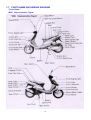
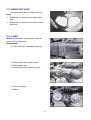
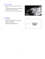
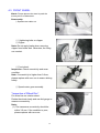
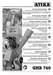
1
TABLE OF CONTENTS 1. GENERAL INFORMATION 1-1 1-2 1-3 1-4 1-5 1-6 1-7 1-8 PAGE SPECIFICATIONS INSPECTION PRECAUTIONS SAFETY PRECAUTIONS SPECIAL TOOLS TIGHTENING TORQUE LUBRICATION POINTS PARTS NAME TROUBLE SHOOTING 3 10 11 12 14 16 18 1-8-1 1-8-2 1-8-3 1-8-4 1-8-5 19 22 23 24 25 Troubleshooting for Failure in Starting the Engine Troubleshooting for Poor skip of Spark Plugs Troubleshooting for No-Skip of Spark Plugs Troubleshooting for Slow Run (Troubled Engine Poor Acseleration and Horse Power 2.INSPECTION AND ADJUSTMENT 2-1 2-2 2-3 2-4 2-5 2-6 2-7 2-8 2-9 2-10 2-11 2-12 2-13 2-14 2-15 3. 3-1 3-2 3-3 3-4 REGULAR MAINTENANCE SCHEDULE INSPECTION AND CHANGE OF ENGINE OIL FINAL GEAR OIL BRAKE SYSTEM TIRE AND TIRE PRESSURE AIR CLEANER BATTERY SPARK PLUG FUEL FILTER CARBURETOR IDLE SPEED THROTTLE VALVE VALVE HEADLIGHT AXLE V BELT CYLINDER PRESSUR 27 28 29 30 35 35 36 37 37 38 38 39 40 40 42 REMOVAL AND INSTALLATION OF ENGINE STANDANTD PREPARATION DATA&SIMPLIFIED TROUBLESHOOTING RELEASE THE ENGINE INSTALLATION OF THE ENGINE CHECK THE ENGINE PARTS 1 43 45 45 45 3-5 3-6 3-7 3-8 FUEL FEED CIRCUIT LUBRICATION DRIVING PULLY-CLUTCH-DTIVEN PULLEY STARTER ARM 4. CHASSIS 4-1 4-2 4-3 4-4 4-5 REMOVAL OF COVER TROUBLESHOOTING OF CHASSIS FRONT WHEEL REAR WHEEL REAR SHOCK ABSORBER 5. ELECTRICAL SYSTEM 5-1 OPERATING CAUTIONS & TROUBLESHOOTING 5-2 BATTERY 5-3 SHORT CIRCUIT TEST 5-4 RECTIFIER 5-5 STARTER RELAY 5-6 STARTER MOTOR 5-7 A.C. GENERATOR 5-8 RESISTOR 5-9 CDI UNIT APPENDIX CIRCUIT DIAGRAM FOR BR8 2 54 59 60 67 70 72 76 78 80 81 86 87 87 88 90 92 94 95 98 1. GENERAL INFORMATION 1-1.SPECIFICATIONS BR8 AIR CLEANER TYPE PAPER FILTER TOTAL LENGTH (mm) 1860 FUEL TANK (ℓ) 6.8 TOTAL WIDTH (mm) 675 TOTAL HEIGHT (mm) 1145 WHEEL BASE (mm) 1270 111 FRONT 72 REAR 114 TOTAL 186 TYPE 4T FUEL TYPE 92/95 UNLEADED GASOLINE CYLINDER NO. BORE ∗ STORKE (mm) DISPLACEMENT (c.c.) STARTER SINGLE 52.4 ∗ 57.8 124 ELECTRIC&KICK COOLING FORCED AIR COOLING LUBRICATION PUMP&SPLASH INTAKE VALVE GAP (mm) 0.08~0.10 EXHAUST VALVE GAP (mm) 0.08~0.10 TOP SPEED (km/hr) 90 IDLING SPEED (rpm) 1800 ±100 MAX. TORQUE (N-m/rpm) 7.90 / 7800 MAX. POWER (kW/rpm) 6.47 /7800 COMPRESSION RATIO CYLINDER PRESSURE (㎏/cm2 – rpm) ENGINE OIL TYPE 9.2:1 SAE 10W - 40 CVK THROTTLE VALVE DIA. (㎜) 24 VENTURI DIA. (㎜) 22.1 THROTTLE VALVE TYPE BUTTERFLY TYPE C.D.I. SPARK ADVANCE BTDC 13°/ 2950rpm SPARK PLUG NGK CR7HSA SPARK PLUG GAP (㎜) 0.6~0.7 BATTERY 12V PRIMA TRANSM. SECONDARY TRANSM. C.V.T. GEAR CLUTCH TYPE CENTRIFUGAL TYPE REDUCTION RATIO HEAD LAMP (H / L) REAR LAMP 7AH PRIMA 1/0.90~2.40 SECOND 1/9.45 (14/43×13/40) 12V 35W/35W×1 12V 5W×1 BRAKE LAMP 12V 21W×1 TURN LAMP 12V 10W×4 130/60-13&130/60-13 FRONT&REAR or120/70-12&130/70-12 or120/70-12&120/70-12 TIRE PRESSURE (kPa) STEERING ANGLE ( °) BRAKE 12.8-570 ENGINE OIL QUANTITY (c.c.) 900 GEAR OIL TYPE CARBURETOR TOTAL TYPE IGNITION 68 ELECTRIC SYSTEM REAR TRANSMISSION 43 LAMP WEIGHT TOTAL WEIGHT (kg) 1 PERSON (75kg) FRONT FUEL SYSTEM MODE DRY WEIGHT (kg) ENGINE PRODUCT SPECIFICATION TIRE DIMENSION BR8 SUSPENSION SYSTEM FRAME SAE 90# GEAR OIL QUANTITY (c.c.) 120 3 FRONT 175 REAR 210 LEFT 45 RIGHT 45 FRONT REAR FRONT REAR DISK DRUM TELESCOPE ROCKER ARM STEEL TUBE TOTAL HEIGHT (mm) 1115 WHEEL BASE (mm) 1280 WEIGHT DRY WEIGHT (kg) TOTAL WEIGHT (kg) I PERSON (75kg) FRONT 47 REAR 68 TOTAL 115 FRONT 78 REAR 112 TOTAL 190 TYPE PAPER FILTER 6.8&3.9 TYPE CVK THROTTLE VALVE DIA. (㎜) 24 VENTURI DIA. (㎜) 22.1 THROTTLE VALVE TYPE BUTTERFLY TYPE C.D.I. SPARK ADVANCE BTDC 13°/ 2950rpm SPARK PLUG NGK CR7HSA SPARK PLUG GAP (㎜) 0.6~0.7 BATTERY 12V 7AH PRIMA TRANSM. C.V.T. SECONDARY TRANSM. GEAR CENTRIFUGAL TYPE 1/0.90~2.40 BORE ∗ STORKE (mm) 52.4 ∗ 57.8 DISPLACEMENT (c.c.) 124 HEAD LAMP (H / L) 12V 35W/35W×1 STARTER ELECTRIC&KICK REAR LAMP 12V 5W×1 COOLING FORCED AIR COOLING BRAKE LAMP 12V 21W×1 TURN LAMP 12V 10W×4 LUBRICATION PUMP&SPLASH INTAKE VALVE GAP (mm) 0.08~0.10 EXAUST VALVE GAP (mm) 0.08~0.10 TOP SPEED (km/hr) 90 IDLING SPEED (rpm) 1800 ±100 MAX. TORQUE (N-m/rpm) 7.90 / 7800 MAX. POWER (kW/rpm) 6.47 /7800 COMPRESSION RATIO 9.2:1 CYLINDER PRESSURE (㎏/cm2 – rpm) 12.8-570 ENGINE OIL TYPE SAE 10W - 40 ENGINE OIL QUANTITY (c.c.) 900 GEAR OIL TYPE SAE 90# GEAR OIL QUANTITY (c.c.) 120 LAMP CYLINDER NO. 92/95 UNLEADED GASOLINE SINGLE FUEL TYPE ENGINE 4T CARBURETOR 715 AIR CLEANER TYPE FUEL TANK (ℓ) IGNIITION TOTAL WIDTH (mm) ELECTRIC SYSTEM BF8 1890 TRANSMISSION MODE TOTAL LENGTH (mm) FUEL SYSTEM PRODUCT SPECIFICATION CLUTCH TYPE REDUCTION RATIO PRIMA SECOND 1/9.45 (14/43×13/40) 130/60-13&130/60-13 FRONT&REAR or120/70-12&130/70-12 TIRE DIMENSION BF8 or120/70-12&120/70-12 TIRE PRESSURE (kPa) STEERING ANGLE ( °) BRAKE SUSPENSION SYSTEM FRAME 4 FRONT 175 REAR 210 LEFT 45 RIGHT 45 FRONT DISK REAR DRUM FRONT TELESCOPE REAR ROCKER ARM STEEL TUBE BR9 PRODUCT SPECIFICATION PAPER FILTER TOTAL LENGTH (mm) 1860 FUEL TANK (ℓ) 6.8&3.9 TOTAL WIDTH (mm) 675 TOTAL HEIGHT (mm) 1145 WHEEL BASE (mm) 1270 74 TOTAL 118 FRONT 72 REAR 121 TOTAL 193 TYPE TYPE CVK THROTTLE VALVE DIA. (㎜) 26 VENTURI DIA. (㎜) 23 THROTTLE VALVE TYPE BUTTERFLY TYPE C.D.I. SPARK ADVANCE BTDC 13°/ 2950rpm SPARK PLUG NGK CR7HSA SPARK PLUG GAP (㎜) 0.6~0.7 BATTERY 12V 7AH PRIMA TRANSM. C.V.T. SECONDARY TRANSM. GEAR CENTRIFUGAL TYPE 1/0.90~2.40 BORE ∗ STORKE (mm) 57.4 ∗ 58.4 DISPLACEMENT (c.c.) 151 HEAD LAMP (H / L) 12V 35W/35W×1 STARTER ELECTRIC&KICK REAR LAMP 12V 5W×1 COOLING FORCED COOLING BRAKE LAMP 12V 21W×1 TURN LAMP 12V 10W×4 LUBRICATION PUMP & SPLASH INTAKE VALVE GAP (mm) 0.08~0.10 EXAUST VALVE GAP (mm) 0.08~0.10 TOP SPEED (km/hr) 97 IDLING SPEED (rpm) 1800 ±100 MAX. TORQUE (N-m/rpm) 11.14 / 6500 MAX. POWER (kW/rpm) 7.89 /7250 COMPRESSION RATIO 10.8:1 CYLINDER PRESSURE (㎏/cm2 – rpm) 11.7-700 ENGINE OIL TYPE SAE 10W - 40 ENGINE OIL QUANTITY (c.c.) 1000 GER OIL TYPE SAE 90# GEAR OIL QUANTITY (c.c.) 120 AIR LAMP CYLINDER NO. 92/95 UNLEADED GASOLINE SINGLE FUEL TYPE ENGINE 4T IGNIITION REAR ELECTRIC SYSTEM TOTAL WEIGHT (kg) I PERSON (75kg) 44 TRANSMISSION WEIGHT DRY WEIGHT (kg) FRONT CARBURETOR AIR CLEANER TYPE FUEL SYSTEM BR9 CLUTCH TYPE REDUCTION RATIO PRIMA SECOND 1/7.8 (15/42×14/39) 130/60-13&130/60-13 FRONT&REAR or120/70-12&130/70-12 TIRE DIMENSION MODE or120/70-12&120/70-12 TIRE PRESSURE (kPa) STEERING ANGLE ( °) BRAKE SUSPENSION SYSTEM FRAME 5 FRONT 175 REAR 210 LEFT 45 RIGHT 45 FRONT DISK REAR DRUM FRONT TELESCOPE REAR ROCKER ARM STEEL TUBE PRODUCT SPECIFICATION AIR CLEANER TYPE PAPER FILTER TOTAL LENGTH (mm) 1890 FUEL TANK (ℓ) 6.8&3.9 TOTAL WIDTH (mm) 715 TOTAL HEIGHT (mm) 1115 WHEEL BASE (mm) 1280 76 TOTAL 124 FRONT 77 REAR 122 TOTAL 199 TYPE TYPE CVK THROTTLE VALVE DIA. (㎜) 26 VENTURI DIA. (㎜) 23 THROTTLE VALVE TYPE BUTTERFLY TYPE C.D.I. SPARK ADVANCE BTDC 13°/ 2950rpm SPARK PLUG NGK CR7HSA SPARK PLUG GAP (㎜) 0.6~0.7 BATTERY 12V 7AH PRIMA TRANSM. C.V.T. SECONDARY TRANSM. GEAR CENTRIFUGAL TYPE 1/0.90~2.40 BORE ∗ STORKE (mm) 57.4 ∗ 58.4 DISPLACEMENT (c.c.) 151 HEAD LAMP (H / L) 12V 35W/35W×1 STARTER ELECTRIC&KICK REAR LAMP 12V 5W×1 COOLING FORCED AIR COOLING BRAKE LAMP 12V 21W×1 TURN LAMP 12V 10W×4 LUBRICATION PUMP&SPLASH INTAKE VALVE GAP (mm) 0.08~0.10 EXAUST VALVE GAP (mm) 0.08~0.10 TOP SPEED (km/hr) 97 IDLING SPEED (rpm) 1800 ±100 MAX. TORQUE (N-m/rpm) 11.14 / 6500 MAX. POWER (kW/rpm) 7.89 /7250 COMPRESSION RATIO 10.8:1 CYLINDER PRESSURE (㎏/cm2 – rpm) 11.7-700 ENGINE OIL TYPE SAE 10W - 40 ENGINE OIL QUANTITY (c.c.) 1000 GEAR OIL TYPE SAE 90# GEAR OIL QUANTITY (c.c.) 120 LAMP CYLINDER NO. 92/95 UNLEADED GASOLINE SINGLE FUEL TYPE ENGINE 4T IGNIITION REAR ELECTRIC SYSTEM TOTAL WEIGHT (kg) I PERSON (75kg) 48 TRANSMISSION WEIGHT DRY WEIGHT (kg) FRONT CARBURETOR BF9 FUEL SYSTEM MODE CLUTCH TYPE REDUCTION RATIO PRIMA SECOND 1/7.8 (15/42×14/39) 130/60-13&130/60-13 FRONT&REAR or120/70-12&130/70-12 TIRE DIMENSION BF9 or120/70-12&120/70-12 TIRE PRESSURE (kPa) STEERING ANGLE ( °) BRAKE SUSPENSION SYSTEM FRAME 6 FRONT 175 REAR 210 LEFT 45 RIGHT 45 FRONT DISK REAR DRUM FRONT TELESCOPE REAR ROCKER ARM STEEL TUBE PRODUCT SPECIFICATION AIR CLEANER TYPE PAPER FILTER TOTAL LENGTH (mm) 1790 FUEL TANK (ℓ) 6.8 TOTAL WIDTH (mm) 675 TOTAL HEIGHT (mm) 1080 WHEEL BASE (mm 1240 58 TOTAL 93 FRONT 63 REAR 105 TOTAL 168 TYPE TYPE CVK THROTTLE VALVE DIA. (㎜) 24 VENTURI DIA. (㎜) 22.1 THROTTLE VALVE TYPE BUTTERFLY TYPE C.D.I. SPARK ADVANCE BTDC 13°/ 2950rpm SPARK PLUG NGK CR7HSA SPARK PLUG GAP (㎜) 0.6~0.7 BATTERY 12V 7AH PRIMA TRANSM. C.V.T. SECONDARY TRANSM. GEAR CENTRIFUGAL TYPE 1/0.77~1/2.19 BORE ∗ STORKE (mm) 52.4 ∗ 57.8 DISPLACEMENT (c.c.) 124 HEAD LAMP (H / L) STARTER ELECTRIC&KICK REAR LAMP COOLING FORCED AIR COOLINE LUBRICATION PUMP&SPLASH INTAKE VALVE GAP (mm) 0.08~0.10 EXAUST VALVE GAP (mm) 0.08~0.10 TOP SPEED (km/hr) 87 IDLING SPEED (rpm) 1800 ±100 MAX. TORQUE (N-m/rpm) 7.90 / 7800 MAX. POWER (kW/rpm) 6.47 /7800 COMPRESSION RATIO 9.2:1 CYLINDER PRESSURE (㎏/cm2 – rpm) 12.8-570 ENGINE OIL TYPE SAE 10W - 40 ENGINE OIL QUANTITY (c.c.) 900 GEAR OIL TYPE GEAR OIL QUANTITY (c.c.) LAMP CYLINDER NO. 92/95 UNLEADED GASOLINE SINGLE FUEL TYPE ENGINE 4T IGNIITION REAR LECTRIC SYSTEM TOTAL WEIGHT (kg) I PERSON (75kg) 35 TRANSMISSION WEIGHT DRY WEIGHT (kg) FRONT CARBURETOR BH8 FUEL SYSTEM MODE CLUTCH TYPE REDUCTION RATIO PRIMA SECOND 1/8.61 (15/42×13/40) 12V 35W/35W×1 or 18W /18W×2 12V 5W×1 BRAKE LAMP 12V 21W×1 TURN LAMP 12V 10W×4 FRONT&REAR 120/90-10&110/90-10 TIRE DIMENSION BH8 TIRE PRESSURE (kPa) STEERING ANGLE ( °) BRAKE SUSPENSION SYSTEM FRAME SAE 90# 110 7 FRONT 175 REAR 210 LEFT 45 RIGHT 45 FRONT DISK REAR DRUM FRONT TELESCOPE REAR ROCKER ARM STEEL TUBE TOTAL HEIGHT (mm) 1160 WHEEL BASE (mm) 1304 WEIGHT DRY WEIGHT (kg) TOTAL WEIGHT (kg) I PERSON (75kg) FRONT 38 REAR 70 TOTAL 108 FRONT 64 REAR 119 TOTAL 183 TYPE PAPER FILTER 6.8 TYPE CVK THROTTLE VALVE DIA. (㎜) 24 VENTURI DIA. (㎜) 22.1 THROTTLE VALVE TYPE BUTTERFLY TYPE C.D.I. SPARK ADVANCE BTDC 13°/ 2950rpm SPARK PLUG NGK CR7HSA SPARK PLUG GAP (㎜) 0.6~0.7 BATTERY 12V 7AH PRIMA TRANSM. C.V.T. SECONDARY TRANSM. GEAR CENTRIFUGAL TYPE 1/0.90~2.40 BORE ∗ STORKE (mm) 52.4 ∗ 57.8 DISPLACEMENT (c.c.) 124 HEAD LAMP (H / L) 12V 35W/35W×1 STARTER ELECTRIC & KICK REAR LAMP 12V 5W×1 COOLING FORCED AIR COOLING BRAKE LAMP 12V 21W×1 TURN LAMP 12V 10W×4 LUBRICATION PUMP & SPLASH INTAKE VALVE GAP (mm) 0.08~0.10 EXAUST VALVE GAP (mm) 0.08~0.10 TOP SPEED (km/hr) 90 IDLING SPEED (rpm) 1800 ±100 MAX. TORQUE (N-m/rpm) 7.90 / 7800 MAX. POWER (kW/rpm) 6.47 /7800 COMPRESSION RATIO 9.2:1 CYLINDER PRESSURE (㎏/cm2 – rpm) 12.8-570 ENGINE OIL TYPE SAE 10W - 40 ENGINE OIL QUANTITY (c.c.) 900 GEAR OIL TYPE SAE 90# GEAR OIL QUANTITY (c.c.) 120 LAMP CYLINDER NO. 92/95 UNLEADED GASOLINE SINGLE FUEL TYPE ENGINE 4T CARBURETOR 715 AIR CLEANER TYPE FUEL TANK (ℓ) IGNIITION TOTAL WIDTH (mm) ELECTRIC SYSTEM BK8 1880 TRANSMISSION MODE TOTAL LENGTH (mm) FUEL SYSTEM PRODUCT SPECIFICATION CLUTCH TYPE REDUCTION RATIO PRIMA SECOND 1/9.45 (14/43×13/40) 80/80-14 & 110/80-14 FRONT&REAR or TIRE DIMENSION BK8 110/80-14 & 110/80-14 TIRE PRESSURE (kPa) STEERING ANGLE ( °) BRAKE SUSPENSION SYSTEM FRAME 8 FRONT 175 REAR 210 LEFT 45 RIGHT 45 FRONT DISK REAR DRUM FRONT TELESCOPE REAR ROCKER ARM STEEL TUBE PRODUCT SPECIFICATION AIR CLEANER TYPE PAPER FILTER TOTAL LENGTH (mm) 1880 FUEL TANK (ℓ) 6.8 & 3.9 TOTAL WIDTH (mm) 715 TOTAL HEIGHT (mm) 1160 WHEEL BASE (mm) 1340 71 TOTAL 110 FRONT 65 REAR 120 TOTAL 185 TYPE TYPE CVK THROTTLE VALVE DIA. (㎜) 26 VENTURI DIA. (㎜) 23 THROTTLE VALVE TYPE BUTTERFLY TYPE C.D.I. SPARK ADVANCE BTDC 13°/ 2950rpm SPARK PLUG NGK CR7HSA SPARK PLUG GAP (㎜) 0.6~0.7 BATTERY 12V 7AH PRIMA TRANSM. C.V.T. SECONDARY TRANSM. GEAR BORE ∗ STORKE (mm) 57.4 ∗ 58.4 DISPLACEMENT (c.c.) 151 HEAD LAMP (H / L) 12V 35W/35W×1 STARTER ELECTRIC&KICK REAR LAMP 12V 5W×1 COOLING FORCED AIR COOLING BRAKE LAMP 12V 21W×1 TURN LAMP 12V 10W×4 LUBRICATION PUMP&SPLASH INTAKE VALVE GAP (mm) 0.08~0.10 EXAUST VALVE GAP (mm) 0.08~0.10 TOP SPEED (km/hr) 97 IDLING SPEED (rpm) 1800 ±100 MAX. TORQUE (N-m/rpm) 11.14 / 6500 MAX. POWER (kW/rpm) 7.89 /7250 COMPRESSION RATIO 10.8:1 CYLINDER PRESSURE (㎏/cm2 – rpm) 11.7-700 ENGINE OIL TYPE SAE 10W - 40 ENGINE OIL QUANTITY (c.c.) 1000 GEAR OIL TYPE SAE 90# GEAR OIL QUANTITY (c.c.) 120 LAMP CYLINDER NO. 92/95 UNLEADED GASOLINE SINGLE FUEL TYPE ENGINE 4T IGNIITION REAR ELECTRIC SYSTEM TOTAL WEIGHT (kg) I PERSON (75kg) 39 TRANSMISSION WEIGHT DRY WEIGHT (kg) FRONT CARBURETOR BK9 FUEL SYSTEM MODE CLUTCH TYPE REDUCTION RATIO PRIMA CENTRIFUGAL TYPE 1/0.90~2.40 SECOND 1/7.8 (15/42×14/39) 80/80-14 & 110/80-14 FRONT&REAR or TIRE DIMENSION BK9 110/80-14 & 110/80-14 TIRE PRESSURE (kPa) STEERING ANGLE ( °) BRAKE SUSPENSION SYSTEM FRAME 9 FRONT 175 REAR 210 LEFT 45 RIGHT 45 FRONT DISK REAR DRUM FRONT TELESCOPE REAR ROCKER ARM STEEL TUBE 1-2 INSPECTION PRECAUTIONS 1. The measurements use IS system for bolts and bolt heads. Please do not use British system for the bolts and nuts, otherwise it can damage the motorcycle. 2. Please clean parts outside deposits before maintenance. Otherwise, the deposits may drop into engine and damage engine in operation. 3. Please use kerosene or diesel to clean-up disassembled parts. Check and measure parts after clean-up. The parts’ contact and sliding surface should apply engine oil for lubrication. 4. The packing, metal gasket, O-ring, seal, clamp, and clipper should be replaced with new ones after disassembly. 5. Please pay attention to the orientation and relative positions of the major components. Arrange the parts in order during disassembly. Make marks if necessary to avoid mistakes in re-assembly. 6. Loosing the parts should start from small to big, from outside to inside, and in alternative parts. Assembly is in reverse order of disassembly procedures. 7. The oil seals should be replaced with new ones after disassembly. The contact surface should be cleaned-up. Check if the contact axle has scratches or burry. Use special tools for assembly to avoid damaging seal lip area, which may lead to oil leak. The manufacturer logo should face outward in assembly. Apply grease at seal lip area. 8. Please do not presses, twist, and over scratch the wire cable to avoid bad wire contact. 9. Disconnect the battery negative (-) terminal before maintenance. Connect the positive (+) terminal first in assembly. Apply a thin layer of grease on terminals, and cover with terminal caps. 10 1-3 SAFETY PRECAUTIONS Warning: Engine Exhaust Please keep good ventilation during engine operation. Do not operate engine in closed-room. The toxic carbon-oxygen (CO) in exhaust may lead human to loss conscious and even death. Warning: Gasoline The gasoline is very easy to burn or explode. gasoline tank or gasoline leak. Forbid any fire during inspection of Warning: Battery H2 and Battery Liquid 1. The battery liquid is toxic sodium liquid. Please do not contact the liquid with skin or eye. If any contact happens, please wash with massive clean water and contact with doctor. 2. The released H2 from battery is explosive. Please keep good ventilation during charging battery and forbid any fire. Watch: Brake Fluid The brake fluid can damage the painting on plastic. Please cover the plastic parts with towel or cloth during maintenance of brake disk. If the brake fluid is split on plastic component, please remove the fluid and wash the surface with water right away. Watch: High Temperature of Engine The engine cover, cylinder, and exhaust pipe have high temperature after starting of engine. Please wear glove in maintenance of parts during engine operation, or maintenance should be waited until engine is cooled. 11 1-4 SPECIAL TOOLS Universal Wrench 440601 Four Legs Sleeve Hold for removing flywheel. Hold for removing belt driver pulley. Hold for removing belt driven pulley. Flywheel Remover 440604 Used for removing starter clutch gear lock nut. 440602 Starter Spring Assembly Tool 440605 Used for removing flywheel. Used for starter spring assembly. Gear Remover Crank Shaft & Right Hand Crank Case 440606 440603 Used for removing starter driven gear. To draw the crank shaft into the right hand crank case. 12 Inner Chain Wrench Bush Remover 440607 440610 For disassembly the camshaft inner chain. For removing the crankcase suspension bush. Socket of Valve Adjusting Bolt 440608 Fixing Nut Socket Adjust the clearance of valve stem and rock arm. Used for removing steering shaft nut. Valve Cotter Tool 440609 For assembling valve cotter 13 440611 1-5 TIGHTENING TORQUE *BR8 Representative Figure* *Standard Torque Values of Bolts and Nuts * Specification Torque (kg-cm) Specification Torque (kg-cm) 5 mm Bolt and Nut 40 8 mm Bolt and Nut 220 5 mm Flange Bolt and Nut 50 8 mm Flange Bolt and Nut 270 6 mm Bolt and Nut 100 10 mm Bolt and Nut 350 6 mm Flange Bolt and Nut 120 10 mm Flange Bolt and Nut 400 6 mm SH Bolt and Nut 90 12 mm Bolt and Nut 550 * Torque Values of Chassis Components * No. Tightening Location Specification Torque (kg-cm) 1 Front Wheel Axle Self-lock Nut M12 500~600 2 Brake Disk Hex Bolt M5 180~280 3 Brake Clipper Tightening Bolt M8x35 210~250 4 Speed Meter Cable Nut X 60 5 Front Fork Bearing Tightening Nut M25x1.0 600~650 6 Rear Wheel Axle Self-lock Nut M16x10 600~900 7 Rear Brake Connecting Rod Bolt M16x32 50~80 8 Rear Brake Pin Self-lock Nut M8 250~270 9 Rear Upper Cushion Tightening Bolt M10×46 200~300 10 Rear Lower Cushion Tightening Bolt M8×35 200~300 14 * Torque Values of Engine components * Tightening Location Specification Torque Quantities (kg-cm) Cylinder Head Bolt M6 80~100 4 Cylinder Stud Bolt M8x182.5 500~800 2 M8x195.5 Cylinder Intake Pipe Stud Bolt 2 M6x50 500~800 2 M6 100~120 2 Muffler & Right Crankcase Upper Tightening Screw M8x42 300~400 1 Muffler & Right Crankcase Lower Tightening Screw M8x38 300~400 1 Spark Plug M10 100~120 1 Valve Gap Adjust Lock Bolt M5 50~90 2 Fuel Filter Nut Cap M30 150~200 1 Cooler Fan Lock CR M6x18 500~800 4 Wire Assembly Lock Screw M6x20 800~1000 2 M22 (R.T.) 800~1000 1 M12 400~600 1 M6x28 100~1200 3 Muffler and Exhaust Pipe Tightening Screw Start Clutch Gear ightening Nut Driven Belt Pully Assembly Gearbox Cover Tightening Bolt M6x35 Gearbox Oil Fill Cover Screw 3 M8 90~150 1 Gearbox Oil Drain Cover Screw M8x12 90~150 1 Clutch Side Cover Screw M6x40 50~80 6 M6x65 Starter Arm Tightening Screw M6x22 15 2 100~120 1 1-6 LUBRICATION POINTS *BR8 Representative Figure* * Chassis * Lubrication Area Lubrication Type Inner Side of Acceleration Lever Grease Steering Bearing Speed Meter Gear Front Wheel Axle Bearing Front Wheel Axle Main and Side Stand Axles Rear Wheel Bearing Seat Cover Lock Speed Meter Cable Throttle Wire Rear Brake Cable Brake Assembly Brake Fluid 16 * Engine * Lubrication Area Lubrication Type Piston and Piston Rings Satisfy SAE 10W-40 and API SE,SG Engine Oil Piston Pin Big End of Connecting Rod Rocker Arm Frictional Contact Area Cam Shaft and Chain Cylinder Frictional Area Oil Pump Chain Gears Contact Surface Bearing Operation Area O Rings Seal Lip Area Starter Frictional Surface High Temperature Durable Grease Starting Cam Gear Spring Operation Frictional Area Generator Connector Adhesives Gearbox Ventilation Tube 17 1-7 PARTS NAME AND WIRING DIAGRAM * Parts Name * *BR8 Representative Figure* 18 1-8 TROUBLE SHOOTING 1-8-1 Troubleshooting for failure in starting the engine Analysis of potential causes Engine does not start See page 17 Check if the crank shaft works Does not work works Check if the starting motor works Does not work Check if the battery is properly charged Bright light Check RPM Poor (too slow) Fair Works Check if the starting gear and the Loosen the carburetor Check battery charging speeding clutch of the starting leakage screw to check and contact of pins motor suffer critical wear, if yes, for inlet of fuel. replace them Poor Dim light or light off Fair Poor Fair Recharge the battery Check the and be sure the pin is starting motor Check Charge the battery or Check for existence for fuel properly secured.(In and the switch replace it. In case of poor of water or other case of poor in the charging, in addition to impurities in the fuel tank charging, proceed carburetor buoyant recharging, check the with a new charging charging system of the Fair and check the Poor power plant for failure. charging system of Poor Noise No noise Fair the power plant for Check failure.) Check the starting a. Poor the Check for fuel Clean the contact of gear and speeding spill in the engine carburetor gear of the starting carburetor starting inside and the Repair No fuel With motor for abnormal switch (piston, fuel filter or fuel engagement. b. Starting bearing Add in replace relay and with Poor Fair Check the fuel designated breaks or others) fuel new filter and the in short for ones Repair or Check skips tubing circuit failure replace c. Loose in spark new contact or Poor buoyant Fair l wiring Fair Poor and needle No Skip valve skip Check fuel tank Clean fuel Correct the Replacement ventilation filter and fuel engagement of new tubing for tubing or of the starting motor obstruction replacement starting and check for Refer to motor with work. 1-8-3 No Skip the speeding in Spark clutch. Check the solenoid switch of the starting motor for noise during work Plugs for checking b a 19 c a c Poor skip b Fair skip Poor Check engine pistons, bearings and others Fair Replace the original starting motor or repair it. Fair Poor Clean ventilation tubing Refer to 1-8-2 Poor skip in Spark Plugs for checking Adjustment or replacement of carburetor buoyant needle valve Check spark plug for cleanliness, normal gap, pollution by gasoline. If yes, check the choke of the carburetor Fair Poor Check if the adjustment screws of the carburetor need to be regulated Clean and adjust spark plug gap or replace with new ones Fair Poor Check choke of the carburetor for troubles Readjustment Poor Fair Check if the slop nozzle of the carburetor is obstructed or the threshold fails Poor Fair Clean or replace the slow nozzle or correct, replace with new threshold Test the compression Fair Adjust or replace new choke parts Poor Check air filter grill Check cylinder washer for leakage, check cylinder, piston, piston ring for obstruction for wear, with correction, adjustment or replacement 20 z No fuel z Dirty fuel filter z Obstructed fuel tubing z Obstructed ventilation tubing of the fuel tank z Poor carburetor buoyant needle valve z Carburetor buoyant with impurities z Poor carburetor buoyant z No skip in spark plugs z Poor skip in spark plugs z Dirty spark plugs z Incorrect spark plugs gap z Dirty and wet spark plugs z Loose adjustment screws in the carburetor z Carburetor choke z Obstructed carburetor slow nozzle z Ailing carburetor threshold z Obstructed air filter grill z Leakage in cylinder washer z Seriously damaged cylinder, piston, piston z Dead battery z Poor contact of battery pin and conductors z Starting switch with poor or failure z Starting relay with broken wire or short circuit z Loose contact and wiring z Starting gear and speeding clutch gear seriously worn z Starting gear and speeding clutch gear in poor engagement z Poor starting motor 21 1-8-2 Troubleshooting for poor skip of spark plugs Analysis of potential causes Poor skip of spark plugs Check for spark plug cap, ignition coil Loose Normal Load in the spark plug Replacement of new spark plug and cap try skip again Poor skip High sparks Check for loose C.D.I. plugs, terminal conduction and resistance values Replacement of poor spark plug Normal Abnormal Poor or abnormal C.D.I. or plugs, replacement of C.D.I. and mount properly the plug Check high-voltage coils, main switches, PICK UP, distributor coil for normality Normal Check for correct main wiring contacts and terminals, if necessary, correct them Abnormal Poor high-voltage coils, main switches, PICK Ups, distributor coils 22 z Loosen spark plugs z Poor spark plugs z Poor high-voltage wiring z Poor distributor coils z Poor PICK Ups z Poor main switches z Wiring relay 1-8-3 Troubleshooting for no-skip of spark plugs Analysis of potential causes No skip of spark plugs Check for proper loading of the spark plug cap Poor Fair Load properly the spark Replacement spark plug and test the plug cap intensity of the spark plugs Intense sparks Weak sparks Replacement of Check for loose C.D.I. poor spark plugs z Loose spark plug cap z Poor spark plug z Loose C.D. adapter z Poor C.D.I. z Poor PICK UP z Poor distributor high-voltage wiring z Poor main switch z Main wiring broken or in short circuit contacts z Ignition coil broken or in short circuit Normal Loose Load properly the C.D.I. adapter z Check C.D.I. terminals passage and testing of resistance Normal Use C.D.I. tester for checks of C.D.I. Normal Check ignition coil for breaking or short circuit, replace when necessary Abnormal a. b. c. d. Poor PICK UP Poor main switch Poor contact of adapter Broken main wiring of short circuit Abnormal Replacement of the poor C.D.I. 23 Poor adapter contact 1-8-4 Troubleshooting for slow run (troubled engine) Analysis of potential causes Poor slow run z z Check for contamination in spark plugs and excessive gap z Poor Fair Cleaning and Alarming abnormality of ignition timing z adjustment adjustment z Fair Poor z Is the air filter grill obstructed? z Fair Poor Replacement of Is the carburetor buoyant the filter grill level normal ? z z Poor Fair Adjustment or replacement of the buoyant needle valve Check if the choke valve fails (valve does not open) ? Poor Correction z Dirty spark plugs Incorrect spark plug gaps Incorrect ignition timing Obstructed air filter grill Poor carburetor buoyant needle valve Poor carburetor choke valve Poor engagement of carburetor and inlet tube Obstructed carburetor slow injection Poor engagement of cylinder head washer Severe wear of cylinder, piston, piston ring Fair Check of for air between the carburetor and the air inlet Poor Fair Add tightening force or Check for obstruction in the replacement of the washer carburetor slow injection Poor Cleaning Fair Test the compression Check for air leakage in the cylinder washer, check wear of cylinder, piston, piston ring and other elements with correction, adjustment or replacement 24 1-8-5 Poor acceleration and horse power Breakdown of potential causes Poor acceleration and horse power z Check for drag of braking drum by braking plate Poor Fair Check for obstructed air filter Adjust or replace braking plate Poor Fair z z z z z z Check for burn of spark Replacement of the Fair Poor Cleaning, adjustment of replacement of new spark plugs z z Poor Test of spark plugs, sparks Poor skip z Check for normal ignition timing Fair See 1-8-2 poor skip of spark plug for checking methods z z filter grill plugs and the gap z Timing z Intense sparks Check carburetor for proper adjustment Fair Poor Adjustment Check for normal choke valve action Poor Correction or replacement Fair Check for obstructed injection nozzle a 25 Braking plate retaining braking drum Air filter grill obstructed Dirty spark plugs Incorrect gap in spark plugs Incorrect ignition timing Poor skip in spark plugs Incorrect adjustment of carburetor adjustment screw Poor choke valve in carburetor Dirty or obstructed carburetor injection nozzle Poor carburetor buoyant needle valve Dirty fuel filter Obstructed fuel circuitry Poor engagement of cylinder washer Serious damage of cylinder, piston, piston ring a Fair Poor Cleaning or replacement Check for normal fluid level in the buoyant Poor (low level) Check of needle valve and buoyant Poor Adjustment or replacement Fair Check fuel pipe and carburetor for obstruction Cleaning or replacement 26 Fair Check the compression Check for leakage in cylinder washer; check cylinder, piston, piston ring for wear. Correct, adjustment or replacement when necessary 2. INSPECTION AND ADJUSTMENT 2-1 REGULAR MAINTENANCE SCHEDULE Explanation: (1) Please follow the regular maintenance schedule to ensure the motorcycle’s function and life. (2) I : Inspection (including clean up, lubrication, refill, or replace parts), C: Clean, R: Replace, A: Adjust. km or time 300 km 1000 km 2000 km 3000 km 4000 km 5000 km 6000 km 7000 km 8000 km 9000 km Maintenance Item Engine Oil (1 mo.) (3 mo.) (6 mo.) (9 mo.) R R R R Oil Strainer Screen R Brake I R R R R R I I Tires R R I I I I I I I I I I R Battery I I I C Fuel Filter C R Carburetor Valve A I I R C R R I C R I I C A A A V Belt I Bolts and Nuts T Note: R C Air Cleaner Spark Plug 12000 C R I 11000 (12 mo.) (15 mo.) (18 mo.) (21 mo.) (24 mo.) (27 mo.) (30 mo.) (33 mo.) (36 mo.) C Gear Oil 10000 (1) If ridden on dusty roads or raining days, please shorten the inspection and replacement schedule for air filter. (2) If ridden under heavy load, frequent long distance travel, please shorten the replacement schedule for engine oil. (3) Please clean the spark plug regularly, and replace the spark plug if necessary. * Regularly Maintenance and Performance Relationship* Performance100% Ridden Time (or Mileage) Curve A: With regular maintenance, the performance can be improved to optimal condition with maintenance at scheduled time. Curve B: Without regular maintenance, the performance drops and engine can be damaged. Therefore, the engine needs repair to re-gain high performance, and the motorcycle’s life can be shorten. 27 2-2 INSPECTION AND CHANGE OF ENGINE OIL Watch: Please place main stand to park the motorcycle for inspection. Inspection: Stop engine for 2~3 minutes when it is warmed. Remove the engine oil level and check if the oil level is bellow the lower limit. Fill engine oil to the level between upper and lower limits. * Change Engine Oil * Note: Please change engine oil according to regular maintenance schedule. If ridden on heavy load or long distance, please shorten the maintenance schedule for oil change. ● Please put oil tray under the left crankcase and remove the oil drain plug. Re-install the drain plug when the engine oil is drained. * Clean up the oil filter * Inspection: (1) If O-ring is damaged, please replace with new one. (2) If there is any deposit, please use clean up before re-assembly. Note: (1) Torque of oil strainer screen: 150 ~ 200 kg-cm. (2) Lubrication Type: SAE 10W-40 Engine oil capacity * BH8 / BR8 / BF8 * 125c.c. Engine disassembled : 900c.c. change oil : 750 c.c. * BR9 / BF9 * 151c.c. Engine disassembled : 1000c.c. change oil : 900 c.c. (3) Check if there is any leakage after oil change. Warn the engine and check the engine oil level again. 28 2-3 FINAL GEAR OIL Watch: Please place main stand to park the motorcycle for inspection. Clean grease around the drain plug. Disassembly: ◎ Oil refill plug. ◎ Oil drain plug. Note: Put an used oil tray under the gearbox before removing the drain bolt plug. Inspection: Check if the oil drain plug washer is damaged. Please replace with new one if it is damaged. ◎ Drain gear oil. Assembly: ■ Assembly drain plug. ■ Refill gearbox oil. ■ Reinstall oil refill plug. Note: (1) Torque on drain plug: 90 ~ 150 kg-cm. (2) Oil type: SAE 90 # (3) Oil capacity * BH8 * Gearbox disassembled : 110 c.c. Regular Maintenance : 90 c.c. * BR8 / BF8 / BR9 / BF9 * Gearbox disassembled : 120 c.c. Regular Maintenance : 100 c.c. (4) Please check if there is any leaking after oil refill. 29 2-4 BRAKE SYSTEM A. Front Brake Lever Free Play Note: Front brake lever free play is 10~20 mm. Adjustment: This motorcycle uses “non-adjust style”. B. Brake Fluid Inspection: The front brake fluid level should above “MIN”. If it is below, refill the brake fluid and check leakage of the brake system. Warning: If there is low or no load when the brake lever is hold, please check if there is air in the brake system or fluid leakage. C. Refill Brake Fluid Watch: Please place main stand to park the motorcycle for inspection. Disassembly: ◎ 2 tightening bolts on fuel cover. ◎ Fuel trap. ◎ Diaphragm. Refill brake fluid to level between MIN and MAX. Assembly: Assembly is in reverse order of disassembly procedures. Warning: (1) Please refill the same type of brake fluid. Different fluid type may create toxic chemical ingredient and can damage the brake. (2) Please do not let water into the master cylinder. Otherwise, the broil temperature may be reduced and bubble can occur, then brake may not work. (3) If the brake fluid is splashed on plastic parts or paints. Please wipe it out right away, otherwise it may affect engine firing. 30 D. Procedure to Release Air (1) Apply suitable plastic tube on drain plug, and put a tray under drain hole. (2) Slowly apply front brake several times. (3) Hold the front brake lever, and do not release the brake lever. (4) Unplug the air release plug, and still hold the brake lever. (5) Tighten the air release bolt, then release the brake lever. (6) Repeat procedure 1 to 5, and release air/bubble completely. Note: Torque of air release bolt: 60 kg-cm. E. Front Brake Disk Inspection: If there is scratches, damage, or wear, please replace with new one. Note: The minimum disk thickness: 3.0 mm. 31 Brake disk eccentricity. Note: A. The max. eccentricity: 0.5 mm. B. If eccentricity is not within the limit, please check tire roundness. If wheel rim roundness is not within the limit, then change the brake disk F. Rear Brake Adjustment Note: The free play of rear brake lever: 10 ~ 20 mm. Adjustment: Adjust the adjustment nut. 32 G. Inspection of Brake Lining and Wheel Rim Inspection: Check the wear indicator plate. If the index is higher than the limit, please check the wear of wheel rim and brake lining. Disassembly: ◎ 2 tightening bolts on exhaust pipe connector. ◎ 2 tightening bolts between exhaust pipe and right crankcase. ◎ Tightening nut on rear wheel axle. ◎ Washer. ◎ Rear wheel. Inspection: check rear wheel rim inner diameter. If it is badly worn, please replace with new one. Note: (1) Please use vacuum to clean wheel rim and lining. Try to reduce the contamination of asbestos fiber, which may affect the human breath system or lead to cancer. (2) Use the Vernier calipers to measure the diameter of wheel rim. If the diameter is larger than 111 mm, then replace with new one. 33 Note: *BH8* Wear limit Ф 111mm minimum. *BR8 / BF8 / BK8 / BR9 / BF9 / BK9* Wear limit Ф 131mm minimum. ◎ Disassemble the brake shoe and brake shoe spring. Inspection: Measure the brake lining thickness with three points of Vernier calipers (two ends and center). If badly worn, please replace with new one (brake shoe and brake shoe spring). Note: (1) Useable thickness is 2.0 mm. (2) If less than useable thickness, please replace with new parts. Assembly: Assembly is in reverse order of disassembly procedures. Note: (1) Torque of rear wheel bearing bolt: 600 ~ 900 kg-cm. (2) Torque of 2 bolts on exhaust pipe connector: 100 ~ 120 kg-cm. (3) Torque of 2 bolts on exhaust pipe and right crankcase: 300 ~ 400 kg-cm. 34 2-5 TIRE AND TIRE PRESSURE Inspection: Check if tire has been cracked, damage, worn, inclusions (stone, nail, glass, etc.). If tire is in poor condition, please replace with new one. Note: Tire specifications: See specification table. * Tire pressure * Watch: Please measure cool tire pressure. Note: Tire pressure. Front tire: 175kPa(1.78 ㎏/㎝ 2 25.38 PSI) Rear tire: 210kPa(2.14 ㎏/㎝ 2 30.45 PSI) Warning: Don’t over-load the motorcycle. The tire may explode with over-load and it is d 2-6 AIR FILTER Disassembly: ◎ Air filter side cover tightening bolt. ◎ Air filter side cover. ◎ Filter tightening bolt. ◎ Filter. Inspection: Check if filter is filthy or broken. If filthy or broken, please replace with new one. Watch: (1) If ridden on dusty roads or raining days, please shorten the replacement schedule for air filter. 35 (2) Don’t start engine when air filter is not installed, otherwise, the piston or cylinder can be damaged. Assembly: Assembly is in reverse order of disassembly procedures. Watch: Please install air filter and side cover closely. 2-7 BATTERY Disassembly: ◎ Foot mat. ◎ Battery box cover. ◎ Disconnect the battery negative “-” cable, and then the positive “+” cable. Warning: Please do not touch tools with frame buring disconnecting positive “+” cable. It can cause short circuit, then it may spark and damage battery. Inspection: This motorcycle use wet type battery. Please fill with distillation water or lead battery fluid when the electrolysis fluid is lower than minimum. Assembly: Assembly is in reverse order of disassembly procedures. Warning: First connect the positive “+” cable, and then negative“-” cable. 36 2-8 SPARK PLUG Disassemble: ◎ Spark plug cap. Note: Please blow away deposits around spark plug with blower before removing spark plug. Otherwise, the dust may drop into cylinder and it can damage engine. Inspection: Check if spark plug has carbon deposits, burned, or cracked. Use steel brush to remove carbon deposits and adjust spark plug gap. Replace burned or cracked spark plug with new one. Note: Spark plug specification: CR7HAS (NGK). Spark plug gap: 0.6 ~ 0.7 mm. Warning: First install the spark plug with hand, and then tighten it with spark plug wrench. Please do not over twist the spark plug. Note: Torque of spark plug: 100 ~ 120 kg-cm. 2-9 FUEL FILTER Inspection: Check if it is hardened, damaged, or leaking. If any above problem exists, please replace with new one. 37 2-10 CARBURETOR IDLE SPEED Note: Please place main stand to park the motorcycle for inspection. Start engine and adjust idle speed at warm engine condition. * Adjust Procedure * ◎ Connect engine speed meter. ◎ Adjust idle speed to adequate range with cross screw driver. Note: (1) Increase engine speed by rotating the screw clockwise. (2) Reduce engine speed by rotating the screw counter-clockwise. (3) Engine idle speed range: 1800±100 rpm. 2-11 THROTTLE VALVE Inspection: Check if the throttle valve operation is smooth. Note: (1) Throttle lever free play: 2 ~ 6 cm. (2) Micro-adjustment is performed at throttle lever. Macro-adjustment is performed at carburetor throttle valve cable. A. Throttle Lever Gap Adjust Procedures: ◎ Open dust boot. ◎ Loose lock bolt. ◎ Adjust by rotating adjust nut. Note: 1. Increase engine speed by rotating nut clockwise. 2. Reduce engine speed by rotating nut counter-clockwise. ◎ Tighten adjust nut after adjustment. ◎ Close dust boot. 38 B. Carburetor Throttle Cable Gap Adjustment Procedure: Note: First, adjust the throttle lever gap. If it does not satisfy the standard, then adjust the carburetor throttle gap. ◎ Loose Tightening bolt. ◎ Rotate the adjust nut. Note: 1. Increase gap by rotating the screw clockwise. 2. Reduce gap by rotating the screw counter-clockwise. Tighten nut after adjustment. 2-12 VALVE Disassembly: ◎ Cylinder head bolt. ◎ Cylinder head. Note: (1) Inspect and adjust are performed at engine temperature lower than 35oC. (2) Rotate the cooler fan, such that the mark on cam shaft gear match the top-dead center position and the “T” mark on flywheel match the mark on crankcase. Then, perform check and adjustment. Adjustment: Use valve adjust wrench to loose tightening bolt, and rotate nut to adjust gap. Note: Intake valve gap: 0.08 ~ 0.10 mm. Exhaust valve gap: 0.08 ~ 0.10 mm. Watch: Check if the gap is correct after bolt is tightened. 39 2-13 HEADLIGHT AXLE Use cross screw driver to adjust the nut. Note: 1. Rotate the nut clockwise for higher light axle. 2. Rotate the nut counter-clockwise for lower light axle. 2-14 V BELT Watch: Please place main stand to park the motorcycle for inspection. Disassembly: ◎ Loose the cooler tube tightening ring. ◎ Kicker starter arm tightening bolt. ◎ Kicker starter arm. ◎ 8 clutch side cover tightening bolts. ◎ Clutch side plate. ◎ Gasket. 40 ◎ Use universal wrench to tight the drive plate, and remove lock nut and gasket. ◎ Drive plate. ◎ V belt. Inspection: Check if the V belt has cracked, threaded, and pilling. If it is in poor condition, please replace with new V belt. Note: (1) Check the belt length. Wear limit: 18.0 mm or 8000km (2) Belt specification: *BH8* BANDO VS BELT 743 20 30 *BR8 / BF8 / BR9 / BF9* BANDO VS BELT 846 20 30 Assembly: Assembly is in reverse order of disassembly procedures. Warning: Please do not apply any grease on pulley and V belt, which can cause belt slip. Note: (1) Diver plate screw is left-threaded. (2) Torque of driver plate nut: 800 ~ 1000 kg-cm. (3) Torque of clutch side nut: 50 ~ 60 kg-cm. (4) Torque of kick starter arm screw: 100 ~ 120 kg-cm. 41 2-15 CYLINDER PRESSURE Note: (1) Check the cylinder pressure at warm engine condition. (2) Use compressed air to blow away deposits around spark plug before removing spark plug. Otherwise, deposits may drop into cylinder and damage engine. Disassembly: ◎ Spark plug cap. ◎ Spark plug. Inspection: (1) Install cylinder pressure gauge. (2) Full open fuel valve. (3) Ignite the starter motor by pressing the start button and measure cylinder pressure. Note: (1) Cylinder pressure *BH8 / BR8 / BF8* 125c.c. engine 12.8 - 570 kg/cm2-rpm. *BR9 / BF9* 151c.c. engine 11.7 - 700 kg/cm2-rpm. (2) Reasons of too high cylinder pressure: A. Carbon deposits at combustion chamber. B. Carbon deposits on piston top surface. (3) Reasons of too low cylinder pressure: A. Valve gap too small. B. Worn valve seat or seat is not completely closed. C. Incorrect valve – timing. D. Leakage due to worn cylinder gasket. E. Worn piston ring. F. Worn piston and cylinder wall. (4) Torque on spark plug 100 ~ 120 kg-cm. 42 3. RELEASE AND INSTALLATION OF ENGINE 3-1 Starterd preparation data & Simplified troubleshooting ※ Disassembling of Crankcase : Before disassembling the crankcase, the engine must at first dismounted and the following operations must be completed: ◎ Air cleaner, carburettor, and air intake mounted. ◎ Starter motor. ◎ Cylinder head cover, cylinder head. ◎ Cylinder, piston. ◎ Clutch cover, drive pully comp, driven pully comp. ◎ Rear wheel, rear shock absorber. ◎ Cooling fan, flywheel magneto. ◎ Oil pump. Standard preparation data for crank, cylinder, piston, and piston rings: Unit: mm 125 c.c. Engine 151 c.c. Engine Item Checking part Standard value Allowable limit Standard value Allowable limit Cylinder Cylinder inner diameter 52.400-52.410 52.500 57.400-57.410 57.500 Roundness - 0.05 - 0.05 Cylinder degree - 0.05 - 0.05 Piston and Piston outer diameter piston rings Inner diameter of piston pin 52.370-52.390 52.300 57.375-57.395 57.300 15.002-15.008 15.040 15.002-15.008 15.040 0.010-0.040 0.100 0.005-0.035 0.100 Top ring 0.015-0.055 0.090 0.015-0.050 0.090 Second ring 0.015-0.055 0.090 0.015-0.050 0.090 Top ring 0.10-0.25 0.50 0.015-0.300 0.50 Second ring 0.10-0.25 0.50 0.015-0.300 0.50 Lateral track of oil scraper ring 0.2-0.7 - 0.2-0.9 - 0.002-0.014 0.020 0.002-0.014 0.020 14.994-15.000 14.960 14.994-15.000 14.960 Inner diameter of the hole at connecting rod 15.016-15.034 small end 15.060 15.016-15.034 15.060 Gap between cylinder and piston Gap between Piston and piston ring Gap of piston ring Gap between piston and piston pin Outer diameter of piston pin Blow with compressed air the parts after cleaning and before measuring. 43 Simplified troubleshooting: ※ In case of bad ignition, not running smoothly in low speed, check if there is white smoke issuing from air intake of the crankcase. If it is the case, dismount the cylinder, piston, piston rings and measure them according to the above table. The causes may be the wear or break of piston pins. ※ If there is white smoke issue from muffler, its causes may be: ◎ Wear or break of piston pins. ◎ Serious wear of pistons and cylinders due to friction. ◎ Wear of connecting rod small end holes and piston rings. ※ Knocking pistons: ◎ Serious damage of cylinders, pistons, and piston rings by friction wear. ◎ Wear of piston pins and piston pin holes. ※ Low compression rate: ◎ Wear or break of piston rings. ◎ Wear or damage of cylinder walls and pistons. ◎ Too narrow gap or no gap at all of valve. ◎ Gap between valve and its seat. ◎ Valve burnt. ◎ Valve untimely. ◎ Spark plug not tightened. ◎Gas leak at cylinder head washer. ※ Too high compression rate: ◎ Piston head or combustion chamber unclean. ※ Abnormal engine noise: ◎ Bearing of the end transmission mechanism loosened. ◎ Bearing of crank loosened. 44 3-2 RELEASE THE ENGINE -Disconnect the terminals of the battery. -Disconnect the electric terminals of the various components. -Disconnect the fuel feed pipe and the vacuum cock control pipe. -Disconnect the throttle valve control wire of carburettor. -Release the rear brake cable. -Release the shock absorber. -Remove the engine mounting shaft screw. 3-3 INSTALLATION OF THE ENGINE -Assemble the engine on the chassis by following the steps described for its disassembly in reverse order. -Inspect the engine lubricate oil with the oil level indicated. -Check the operation of the carburetor and accelerator. -Adjust the rear brake. 3-4 CHECK THE ENGINE PARTS 3-4-1 Air Cleaner -Remove the seven fixing screw of the air-cleaner cover. -Inspect the filter is keep clean or not. -Change a new filter, if it is badly dirty or broken. 3-4-2 Spark Plug -Unscrew the spark plug with specified tool. -Examine the spark plug does any dirty, deposit carbon or burn out? -Clean the spark plug if has dirty or deposit carbon with steel brush. -Measure the clearance of the spark gap. -The gap standard is 0.6-0.7 mm 3-4-3 Cylinder head and Timing -Remove the fan cover, cooling fan and shroud set. -Release the cylinder head cover bolt, remove the cylinder head cover. -Turn the flywheel with clockwise direction, let the “T” mark on the flywheel point to the rib mark on crankcase. Then, the circle hole mark on the cam shaft gear will be upward position. Such position, the engine at top dead point position. -Remove the nuts and washers of the camshaft holder. -Remove the camshaft holder and dowel pins -Disassembly the chain gear and take the camshaft off. -Inspect the cam surface and the bearing. -If cam surfaces are serious abrasived and the bearings are damaged replaced with a new one. 45 -Pull out the rocker arms shaft and inspect that the rocker arms should not be worn and the oil hole is not obstructed. -Pulling cylinder head gently off the cylinder. -Remove the dowel pins, cylinder head gasket and the chain guide rod. -Clean the coupling surfaces with carefully not to damage them. -Clean the combustion chamber, ridding any carbon deposits. -Check that the valve seats. -Examine the combustion chamber and shown no sign of cracks or damage. -Use a calibrated rule, inspect the cylinder head lower surface is perfect flatness. -Use a thickness gauge, inspect that the surface wear does not exceed 0.05mm. -Measure the free length of the valve springs. The limit of inner spring is 31.2mm. The limit of outer spring is 34.1mm. -Examine the valves should not be damaged, cracked, burnt or bended. Clean the valve, removing all carbon formation and measure the diameter of vale axle. The wear limit is 4.9mm. Inspect the condition of the seat on the valve head, damaged or cracked are not allowed. 46 -Inspect the valve seats and show no signs of damages or crack. Measure the inside diameter of valve stem seal. Wear limit of inlet valve stem seal is 0.08mm. Wear limit of exhaust valve stem seal is 0.10mm. -Measure the width of the impression on the valve seat. Wear limit is 1.8mm maximum. -Lubricate the valve stems and suit them to the guides. lock cones. -Fit the valves with special tool carefully. The springs may come off, it is dangerous. -Gently tap the valve stems with a plastic nammer to make the cones in their seats. Be carefully, when doing this work. -Insert the two rocker arms shaft. -Fit a new cylinder head gasket and keep the surfaces of gasket and keep the surfaces of gasket clean. 47 Fit the springs, the upper cups and the -Assembly the cylinder head. -Turn the flywheel, Let the “T” mark on the flywheel to aim at the rib mark on the crankcase. The circle hole on the camshaft gear is upward and the two mark line on the camshaft gear match with surface of the cylinder head. Fit the camshaft gear and fit the chain on this camshaft gear. -Fit the dowel pin. -Fit the camshaft holder. Fit the nuts on the related studs and tighten them by diagonal step. Tightening torque is 200 kg-cm -Install the chain guide. Loose the lock by turning the nut with counter-clock direction. -Adjusting the valves Should align with rotate the crankshaft by hand until the circle hole marks on camshaft gear wheel and the other two mark line cylinder head, then adjust the plays of the valves with special tool and with the aide of a thickness gauge measure the gap between the rocker arm adjusting bolt abutting end and the valve stem. Clearance: Inlet valve gap: 0.08 ~ 0.10 mm Exhaust valve gap: 0.08 ~ 0.10 mm -Assemble the head cover. Replace the sealing ring with a new one, install the cover and screw the four bolts. 48 3-4-4 Cylinder and piston -After removing the cylinder head and gasket, take out the cylinder. -Take off the cylinder gasket and clean the crankcase surface. -Place a clean cloth under the piston to prevent any dust from falling inside the crankcase chamber. Remove the piston pin circlip and the piston. -Inspect the cylinder inside surfaces show no signs of seizure or anomalous wear, then measure the inside diameter of the cylinder with a bore meter. Note: *BH8 / BR8 / BF8* 125c.c. engine Wear limit Ф52.5mm. * BR9 / BF9* 151c.c. engine Wear limit Ф57.5mm. -Take measurements on three planes along the cylinder axis; for each plane take a measurement on the circumference. -Take off the piston rings carefully. Inspect the piston surface, anomalous wear is not allowed. Note: *BH8 /BR8/ BF8 / BK8* 125c.c. engine Wear limit ∅52.5mm. *BR9/ BF9 / BK9* 151c.c. engine Wear limit ∅57.5mm. 49 -Measure the clearance between the ring and the groove. The max. clearance of top ring is 0.09mm. The max. clearance of 2nd ring is 0.09mm too. -Measure the diameter of the piston pin hole. Wear limit is Ф15.04 mm. -Measure the piston pin outside diameter. Wear limit is Ф14.96 mm. -Measure the inside diameter of the piston-rod small end. Wear limit is Ф15.06mm. 50 -Put the piston ring into the cylinder and measure the clearness of opening by thickness of opening by thickness gauge. Replaced if it exceeds 0.5mm. -Fitting the rings on the piston. Take care not to damage the rings during the fitting and position them as shown in the figure. Once fitted, the rings must rotate freely in their grooves. -The 2nd ring is engraved “2R” mark. The 1st ring is engraved “R” mark. The mark should face upwards while installing. -Assemble the piston, the “IN” reference mark is at the inlet valve side. Insert the piston pin and assembly rings. Assemble the circlip carefully. -Fit the cylinder gasket and cylinder. 51 3-4-5 Crankcase-Crankshaft -Remove the chain and chain guider. -Remove the oil divider and then remove the driving sprocket. -Remove the coupling bolts, gasket and pin. -Take out the crankshaft from crankcase. -Check the side play of the piston-rod big end with a thinness gauge. Wear limit is 0.5mm. 52 -Measure the offset between the two shafts of crankshaft. Maximum offset is 0.1mm. -Bearing Before removing the bearings, make sure that they rotate freely and have no play in their respective housings. -Fit the crankshaft and smear the coupling surfaces with Loctite fixing glue. -Fasten the flywheel-side crankcase half to the transmission-side crankcase half. -Fit the crankcase halves coupling screws. Tightening torques 90 kg-cm. 53 3-5 FUEL REED CIRCUIT 3-5-1 Carburetor Disassemble all carburetor components, clean them with solvent, then dry them with compresses air. Pay special attention to the ducts in carburetor body. Carefully check the condition of all components. The needle may be worn, replace it. The throttle must slide free in the carburetor. If there is excessive play due to wear the throttle must be replaced. Using the new gaskets when reassembling the carburetor. Inspect if the pressure piston is worn or presents notches, Inspect the vacuum membrane carefully. Damaged or cut are not allowed. 3-5-2 How to take off the carburetor -Remove the fuel feed pipes. -Remove the automatic by choke connector. -Loosen the throttle control cable adjusting nut and disconnect the throttle control cable from the carburetor. -Loosen the air filter fastening strap and remove the carburetor. 54 3-5-3 Automatic Choke The needle of automatic choke must keep well. Notches, signs of wear, scratches or other damage are not allowed. 3-5-4 Membrane chamber -Loosen the drain screw and let the fuel flow out from the float chamber. -Remove the two screws of the pressure chamber. 55 -Remove the compression spring and the pressure piston -Remove the needle holder and the needle from the piston. Inspect the pressure piston and membrane. Notches, scratches or other damage are not allowed. -Fit the needle, the spring and the needle holder in the pressure piston and fix the needle holder. -Fit the pressure piston in the carburetor body. -Fit the compression spring. -Fit the pressure chamber cover and fasten it with two screws. 56 3-5-5 Float/Needle valve/Jets -Unscrew the four float chamber screws. -Remove the float pivot, the float and the needle. -Inspect the needle valve and its seat. Notches or deep scratches are not allowed. -Remove the main jet, choke jet and idling jet. Inspect these jets. 57 -Before fitting the parts again, blow all parts, and in particular the housings of the jets, with compressed air. -Clean the main, choke and idling jets with a detergent solvent and blow them with compressed air. -Fit the main, choke and idling jets. -Fit the seat of the needle valve. Fit the needle valve. the float and the float pivot -Measure the float height while its tongue touches the needle valve. Distance between the float and the float chamber plane is 18.5mm. Replace the float if the level is not as indicated. Fit the float chamber. 3-5-6 Throttle Valve Loosen the fastening screws and remove the throttle valve. Check that the valve rim shows no deep scratches. Fix the throttle valve again with Anti-loosen glue and new screws. Note: Before tightening the two screws of throttle valve, carry out the following ti (a) Loosen the slow running adjuster completely, so as to enable the throttle to close the duct completely. (b) Proceeding with the utmost care, manually position the throttle in completely closed position. (c) Tighten the screws while holding the throttle in place. (d) Make sure the throttle is correctly repositioned. 58 3-6 LUBRICATION 3-6-1 Engine oil level The engine must be in cold and the scotter positioned uprightly on its stand flat ways. Inspect the oil level with the oil meter that remove it from the crankcase. If the level is close to the minimum point and the oil is not to be renewed, fill up with oil of the recommended type. 3-6-2 Oil renewal Renew the oil easily while the engine is in hot condition. Place a vessel under the engine, remove the outlet bolt and the oil lever gauge. After draining the oil, clean the oil lever gauge (check the O-ring seal) and fit the oil lever gauge and outlet bolt again. Tightening torque: 150 kg-cm Supply the engine with recommended oil through the oil filter Screw the filler plug. Lubrication Type: SAE 10W-40 Engine oil capacity *BH8/BR8/BF8* 125c.c. Engine disassembled:900c.c. Chang oil: 750c.c. *BR9/BF9* 151c.c. Engine disassembled:1000c.c. Chang oil: 800c.c. Note: Run the engine after a few minutes, then recheck the oil level again when the engine is until cold condition. The oil level should always be kept below the max. lin and above the min. line. 59 3-7 DRIVING PULLY-CLUTCH-DRIVEN PULLEY 3-7-1 Transmission cover -Loosen the fixing screw of cooling duct and remove the cooling duct. -Remove the kick starter lever Assy.. -Remove the clutch cover screws by diagonal step and then remove the clutch cover. -Take off the knock pins and remove the gasket. 3-7-2 Driving pulley -Use the special tool to lock the fixed drive face and loosen the central nut with wrench. -Remove the belt from the spacer and remove the drive pulley Note: Press the movable drive plate and drive pulley face while removing the drive pulley face Assy. in order to avoid the roller to stand up. 60 3-7-3 Driven pulley -Remove the central nut of clutch housing with a compass spanner to hock the housing bell and loosen the nut with wrench. -Remove the driven pulley comp and belt. 3-7-4 Checks *Drive belt -Be sure that the drive belt should not be cracked or damaged. -Measure the belt length. Wear limit: 18.0mm or 8000km 61 -Remove the movable drive plate guide blocks and rollers. Take care to make the mark on the rollers and groove of drive face in order to install rollers correctly. *Rollers Inspection that the rollers should not to be damaged or worn. *BH8* Wear limit Ø18.0mm minimum. *BR8/BF8/BR9/BF9* Wear limit Ø17.4mm minimum. *Roller Bush Inspection that the internal bushing of drive bush should show no signs of anomalous wear and with bore meter to measure its inside diameter. *BH8* Wear limit Ø25.0mm maximum. *BR8/BF8/BR9/BF9* Wear limit Ø24.06mm maximum. Note: Take care to replace the rollers in their original positions. 62 *Spacer -Make sure the spacer surface should not be damaged. -Measure the outside diameter of the spacer. *BH8* Wear limit Ø26.0mm minimum. *BR8/BF8/BR9/BF9* Wear limit Ø23.94mm minimum. 3-7-5 Guide shoes -Inspect the guide blocks should not be worn and then inlay them into the movable drive plate. Assemble the movable drive plate cover. 63 3-7-6 Clutch housing -Inspect for any unusual damage and color change. -Replaced if the inside diameter exceeds 125.5mm. 3-7-7 Driven pulley -Remove the central nut with compass spanner to lock the driven pulley. -Warning: Press tightly the driven pulley while unscrewing the nut, so that the spring will not jump out. 3-7-8 Retaining sheet -Pull out the retaining sheet by hand -Pull out the guide pins and extract the movable drive face from the fixed driven face 64 3-7-9 Fixed driven face comp -Measure the outside diameter of the fixed driven face bush. -Wear limit Ø33.94mm 3-7-10 Movable driven face comp -Measure the inside diameter of the movable drive face. -Wear Limit Ø34.06mm. 3-7-11 Spring -Measure the free length of the movable driven face spring. -Replaced if the free length of spring is less than 135mm. 3-7-12 Fixed driven face comp bearings -Push out the old bearings and install the new one with the tube that has corresponding length and suitable diameter. 65 3-7-13 Clutch -Make sure that should not be oil strained, cracked and unusual damaged from the appearance. -Replaced if the thickness of lining is less than 1.5mm 3-7-14 Fitting -Install the fixed driven face comp into the movable driven face comp. Avoid to damage the lip of oil seal. -Install two O-rings and apply grease to the groove of the cam then fit the guide pins. -Apply a little grease inside of the spring sheet and manually push the spring sheet in lightly and the install the spring and screw the central nut. 66 3-8 STARTER ARM Disassembly: ◎Loose cooler tube tightening ring. ◎ Starter arm tightening bolt. ◎ Starter arm. ◎ 8 clutch side cover tightening bolts. ◎ Clutch side cover. ◎ Gasket. ◎ Pin. ◎ Use universal wrench to hold drive plate and remove drive belt pulley assembly. ◎ Belt. 67 ◎ Starter arm washer. ◎ Spring stop plate. ◎ Spring. ◎ Starter arm. ◎ Starter cam assembly. Inspection: (1) Check if starter arm surface and collar are worn and damaged. (2) Check if starter cam gear surface is worn and damage. (3) Check if starter cam and starter arm loaded surface are worn and damaged. 68 Assembly: Assembly is in reverse order of disassembly procedures. Note: (1) Apply grease on starter arm collar and cam loaded area for lubrication. (2) The starter cam locking pin should match with crankcase fillister for assembly. (3) The mark on starter axle gear should match mark on starter cam. (4) Use special tool for starter arm spring assembly. Rotate tool clockwise, such that spring locking pin is positioned under crank case half-moon location, then assemble stop plate. Note: (1) Torque of starter arm spring plate tightening bolt: 90 kg-cm. (2) Torque drive plate tightening nut: 800~1000 kg-cm. (3) Torque of clutch side cover bolt: 50~80 kg-cm. (4) Torque of starter arm tightening bolt: 100~120cm. 69 4 CHASSIS 4-1. REMOVAL OF COVER *BR8 Representative Figure* 70 * Dismount floor panels following the sequence shown in the list: Helmet Case. Mirror, Rear View. Carrier. Cove Handle Bar, Upper. Bottom Plate. Leg Shield Front. Right and Left Side Cover. Front Fender. Cover Set, Leg Shield Fender, Fixed, Front. Cover Handle Bar, Under. Leg Shield Side, Lower. Leg Shield, Rear. Leg Shield, Lower. Cautions: 1. Do not damage cover of body panels while dismounting. 2. Handle with care regarding lugs of to avoid damage dismounting. 3. When remounting, do not scratch or crash wiring. 4. While assembling every lug shall be fixated effectively. 5. While assembling, make matching panels and their slots. 71 4-2. TROUBLESHOOTING OF CHASSIS nSTEERING/ SUSPENSION/ FRONT WHEELS/ FRONT BRAKES Operation Cautions: 1. Leg shield lower must be dismounted before the front wheel is dismounted. Use a jack to raise the wheel above ground and support the car body firmly. 2. The brake inner cylinder and lining shall be kept free form grease during operation to avoid driving danger caused by braking effort reduced by grease. Troubleshooting Steering too tight (heavy) 1.The bolt of ball bearing fastening at the top of the steering column too tight. 2. Balls of the steering system broken. 3. The conical base for steering ball bearings damaged. 4. Bad curvature of the front fork comp. 5. Bad curvature of the front wheel shaft or deviation of the tire. 6. Insufficient tire pressure. Straight driving impossible due to deviation of the steering wheel: 1. Deviation of the front fork comp. 2. Unequal working of the left and right shock absorber beside the front fork comp. 3. Running deviation due to the deviation of the front axle. 4. Deformation of the front tires. 5. Deformation of wheel rim. Front shock absorber too flexible: 1.Shock absorber spring constant too low. 2. Shock absorber spring fatigue. 3. Lack of oil in the shock absorber resulting from leakage. 4. Loose front fork comp axle bolts. 72 Abnormal noise of working front shock absorber: 1.Noise coming from friction between the shock absorber and the outer tube joint. 2. Noise coming from friction between the shock absorber spring and the outer tube. 3. Noise coming from shock absorber deviation due to loosen screws. 4. Deformed moving parts of the absorber. Too large sway of front wheels: 1. Deformed wheel rim. 2. Insufficiently tightened bolts of front wheel spindle, or although tightened but becoming loose. 3. Sway caused by too large gap around the front wheel bear or damaged bearing. 4. Bad of worn tires. Inefficient braking 1. Unclean or oily friction lining surface. 2. Excessive wear of the friction lining. 3. Deviated or deformed brake discs. 4. Inefficient braking due to air resistance caused by air unduly existing in the braking system. 5. Insufficient brake fluid. 6. Deteriorated brake fluid. 7. Brake fluid pipe clogged. 8. Improper mounting of brake caliper body. 9. Uneven wear of the lining in the brake caliper. 10. Damaged grease seal of the piston of the brake caliper. 11. Bent brake rod. Difficult to operate the brake rod: 1. Brake fluid pipe clogged. 2. The brake caliper not working well. 3. The piston the main cylinder not working smoothly or seriously damaged. 4. The brake rod bent. 73 Uneven braking effort. 1. Unclean brake lining or brake disc. 2. Bad mounting of wheels causing serious sway. 3. Deformed brake disc. 4. Clogged brake fluid pipe. 5. Serious wear of the brake caliper lining. 6. Serious damage of the grease seal of the brake caliper piston. 7. Deteriorated brake fluid. 8. Resistance due to air existing in the brake system. 74 o. REAR WHEELS/ REAR BRAKES/ REAR SUSPENSIONS Operating Cautions: Do not leave greasy the surface of the brake lining inside the brake drum. Troubleshooting: Serious sway while rear wheel rotates. 1. Distorted wheel rim. 2. Tire in bad state. 3. Defective mounting of wheel propeller shaft pieces. Inefficient rear brake (Drum type): 1. Bad adjustment of the brake. 2. Serious wear of the brake drum. 3. Serious wear of the brake cam shaft. 4. Serious wear of the friction face between the rear brake lining and the cam shaft. 5. Wear of the rear brake lining. 6. Unmatched parts in the chisel groove of brake arm. Rear shock absorber too flexible: 1. Absorber spring constant too low. 2. Fatigue of the absorber spring. 75 4-3 FRONT WHEEL Watch: Please place main stand to park the motorcycle for maintenance. Disassembly: ◎ Speed meter cable nut. ◎ 2 tightening bolts on clipper. ◎ Clipper. Note: Do not apply brake when removing clipper from brake disk. Otherwise, the lining can contact. ◎ Front wheel. Inspection: Check eccentricity and wear condition. Note: If eccentricity is higher than 0.2mm, please replace with new one to ensure driving safety. ◎ Speed meter gear assembly. *Inspection of Wheel Rim* Put wheel rim on rotation stand. Rotate the wheel slowly and use dial-gauge to measure eccentricity Note: (1) The transverse eccentricity should be within 3.0 mm. If the condition is poor, please replace with new one. 76 (2) The lateral eccentricity should be within 3.0mm. If the condition is poor, please replace with new one. *Be Careful Items in Assembly* (1) Speed meter gear assemble fillister and wheel hub flange should be fully matched. (2) The wheel hub flange fillister and front fork flange should be fully matched. Note: (1) Torque of rear wheel axle self-lock nut: 600~ 900 kg-cm. (2) Torque of brake clipper tightening bolt: 210 ~250 kg-cm. (3) Torque of speed meter cable nut: 60kg-cm 77 4-4 REAR WHEEL Watch: Please place main stand to park the motorcycle for maintenance. Disassembly: ◎ Exhaust pipe. ◎ Lock screw nut and washer. ◎ Rear wheel. Note: (1) Please use vacuum to clean wheel rim and lining. Try to reduce the contamination of asbestos fiber, which may affect the human breath system or lead to cancer. (2) The transverse eccentricity should be within 3.0mm. If the condition is poor, please replace with new one. (3) The lateral eccentricity should be within 3.0 mm. If the condition is poor, please replace with new one. ◎ Brake lining assembly (brake shoe, brake shoe spring). Inspection: Use 3 points of Vernier calipers (two ends and center) to measure lining thickness. If lining is badly worn and thickness less than 2.0 mm. Please replace with new assembly (brake shoe, brake shoe spring). Warning: Please do not apply any grease on brake lining, which can lead to unsafe drive. 78 ◎ Loose rear brake adjusting nut and remove brake cable. ◎ Brake arm cover. ◎ Brake spring. ◎ Rear brake connecting rod. ◎ Rear brake cam axle. Assembly: Assembly is in reverse order of disassembly procedures. Watch: Please apply thin layer of grease on contact area of cam axle, pin and lining. Do not apply too much grease. Note: (1) Torque of rear brake connecting rod bolt: 50 ~80 kg-cm. (2) Torque of lock pin nut: 250 ~270 kg-cm. (3) Torque of rear wheel self-locking nut: 600 ~ 900 kg-cm. 79 4-5 REAR SHOCK ABSORBER Watch: Please place main stand to park the motorcycle for maintenance. Disassembly: ◎ 2 attaching bolts on air filter. ◎ Air filter. ◎ Upper and lower attaching bolts on rear shock absorber. ◎ Shock absorber. Inspection: Check if the shock absorber is worn, scratched, leaking, or bent. If its condition is poor, please replace with new one. Note: Torque of shock absorber upper and lower attaching bolts: 200 ~ 300 kg-cm. 80 5. ELECTRICAL SYSTEM 5-1. Operating Cautions & Troubleshooting Operating Cautions: 1. Warning: a. The liquid in the battery is diluted sulfuric acid that is dangerous. If, your skin or eye unfortunately get contact with it, please wash with water abundantly and consult immediately a doctor, lest you should lose vision. b. If your clothes is touched by the electrolyte, your skin would also be touched. Therefore you should get it off and wash with water abundantly. 2. Check if electrolyte in the battery is sufficient. If not, add distilled water till the liquid level reach the upper limit line. 3. The battery is rechargeable after discharging. If it is unused after discharge, it may deteriorate and shorten service life. It will become less efficient. After usage of 2~3 years, battery capacity will decrease. It can be regained by recharging several times. 4. When there is other loads while igniting, if the voltage will rise again after an abrupt falling, it is normal. 5. If a battery is unused during a long time, its energy storage will decrease by its auto-discharge. Therefore, a recharging is necessary around every 3 months. 6. To charge a battery, it shall be removed from the car and its filler plugs removed. To put the charging current ‘ON’ or ‘OFF’, you must operate at the charger’s switch. You shall not connect or pull off directly on the battery because electric spark may provoke hydrogen explosion. 7. During battery charging, hydrogen (H2) is produced. It is an inflammable gas. Fire must be forbidden. 81 8. At recharging a battery, the temperature of electrolyte shall be lower than 45℃. 9. To test if a battery is fully charged, please use a voltmeter. Never use ‘Spark method’. 10. When there is current in an electrical installation, please do not pull off a contact then connect it again, because resulting over voltage may damage electronic parts in the commuter. Therefore, this operation must be done after the main switch is put ‘OFF’. 11. If fresh electrolyte is poured in a new battery, a voltage will be generated after a certain lapse of time. If the voltage is not sufficient, then a recharging is necessary. A recharged new battery has necessarily a longer lifetime. 12. The C.D.I of the ignition system shall not fall swinging and be shocked. It is a cause of frequent breakdown. Therefore, a special precaution is necessary in its dismounting and remounting. 13. Bad contact between plug and jack causes often the breakdown of the ignition system. Therefore, before undertaking repair, the contact is to be checked at first. 14. Spark plugs of a suitable heat value and gap are to be used. Otherwise, engine will not work smoothly or break. 82 Troubleshooting: Battery Recharging System: No voltage: 1. Battery cable fallen or disconnected. 2. Fuse fused. 3. Defective of flywheel magneto. 4. Excessive battery discharging: a. Electrolyte leaked. b. Chemical reaction in battery. c. Short circuit in battery. d. Defective rectifier. Low voltage: 1. Insufficient recharging. 2. Leaking of electrolyte. 3. Defective separator causing short circuit between positive and negative plates. 4. Defective battery terminals. 5. Defective recharging system. 6. Defective rectifier. Excessive specific weight of electrolyte: 1. Insufficient recharging. 2. Leaking of electrolyte. 3. Reaction between sulfuric acid and pole plates. Too low capacity: 1. Insufficient recharging. 2. Pole plates react with sulfuric acid. 3. Insufficient electrolyte. 4. Active matter fallen from pole plates because of excessive recharging. 83 Inefficient recharging system: 1. Bad contact at connectors, short circuitry, or broken circuit. 2. Defective rectifier. 3. Defective of flywheel magneto. a. Armature winding short circuited or broken. b. Magneto coil short circuited or broken. Bad electric continuity: 1. Bad contact at battery connection. 2. Ignition system short circuit or bad contact at connectors. 3. Lighting system short circuit or bad contact at connections. Ignition System: Dysfunctioning of spark plugs: 1. Defective of flywheel magneto. 2. Defective high-tension coil. 3. Defective C.D.I . 4. Defective spark plugs. 5. Defective conductor contact, breaking, or short circuit, for example: a. Conduction between flywheel magneto and C.D.I . b. Conduction between C.D.I and the main switch. c. Conduction between C.D.I and the high-tension coil. Engine not running smoothly: 1. Defective ignition first circuit: a. Bad contact in circuitry or cable. b. Defective of flywheel magneto. 2. Bad ignition secondary circuit. a. The ignition coil insulation defect causing electric leakage. b. Defective magneto coil. I. Short circuit between coil layers. II. Defective coil. 84 c. d. 3. Defective spark plug. I. Spark plug covered by carbon. II. Electric leakage in ceramic part of spark plug. Electric leakage from spark plug rubber screen. Defective ignition timing. a. Defective flywheel magneto. b. Defective C.D.I . c. Too large gap of spark plug. d. Too high electric resistance of spark plug. Starter System Starter motor unable to run. 1. Damaged battery. 2. Battery circuit broken, bad contact or too large resistance at connections. 3. Fuse fused. 4. Defective main switch. 5. Defective front and rear brake switches. 6. Defective starter motor switch. 7. Defective starter motor relay. 8. Defective starter motor. 9. Circuitry conductor defective or broken. 10. Starter motor drive pinion locked with the over speed clutch gear. Weak drive of starter motor: 1. Insufficient recharging of battery. 2. Bad contact on circuit conductors. 3. Strange object introduced in the starter motor pinion. 4. Armature shaft bent. 5. Commutator unclean or worn. 6. Brush worn or spring too weak. 7. Starting motor of relay defective. 85 5-2. BATTERY A. Cautions in battery inspection and generator charging. Inspection: Use gravity gauge to measure electrolyte. White is fully charged, yellow means charge is required, and red is broken or almost totally discharged. Note: Electrolyte’s specific gravity and charge level comparison table (20oC). Electrolyte Specific Gravity Charge Level 1.280 1.250 1.220 1.190 1.120 Full 3/4 1/2 1/4 Totally Charged Charged Charged Discharg B. Charge by generator Connecting battery and gener terminals by “+” with “+” and “-” with “-”. Warning: Battery releases explosive gas during charging or use battery. Therefore, it is dangerous to do so in concealed location. Please put battery in good ventilation location during charging, and forbid fire. Note: (1) Standard charging current: 0.6 A for 5~10 hours. (2) Quick charging current: 6.0 A for 30 minutes. (3) Please do not use quick charge except for emergency. (4) Measure the battery voltage 30 minutes after battery is charged. The battery voltage should be higher than 12.8 V. C. Battery manufactured month and charge time comparison. Manufactue Within After 6 mo. Months 3 mo. 3 mo. Charge Add electrolyte 10 20 Time And wait 30 m. hr. hr . 10 mo. Within Over 1 yr. 1 yr. 30 40 60 hr . hr . hr . 86 5-3 SHORT CIRCUIT TEST Disassembly: Disconnect battery negative terminal cable. Measure method: A. Connect megga meter “+” terminal to battery “-” terminal. B. Connect megga meter “-” terminal to circuit negative bl Note: User megga meter “A” current position. Turn main switch to “OFF” position. Inspection: Check if there is electrical current. If no current, check the main switch and wire harness for short circuit. 5-4 RECTIFIER Watch: (1) Check if wire harness is normal before checking rectifier and end resistor. Check if rectifier socket is well connected. (2) Keep fingers away from tester probe. The circuit resistance can be changed with human body resistance involved. Rectifier Terminal Resistance Table. Meter+ Meter- White/Red Yellow/Red White / Red Infitity Yellow/ Red Infitity Red Infitity Infitity Black Infitity 5k-100k Ohm 87 Red Black 3k-100k Ohm Infitity Infitity 3k-100k Ohm Infitity Infitity 5-5 STARTER RELAY A. Operation of starter relay. Watch: Please place main stand to park the motorcycle for inspection. Inspection: Turn the main switch to “ON” position and press the starter button. Note: (1) If there is a snap sound, then the function is normal. (2) If there is no snap sound, then the function is abnormal. Please check: 1. Starter relay ground circuit. 2. Starter relay voltage. B. Starter relay ground circuit Disassembly: Connect the start relay connector and electric tester by: A. Megga meter‘s positive terminal with the relay yellow/red terminal. B. Connect the negative terminal with ground circuit and press the starter button. Then, check the electricity continuity. Note: (1) There should be continuity when pressing the start button. (2) If there is no continuity when pressing the starter button, then check the continuity between starter button and connecting cable. C. Check starter relay voltage. Watch: Please place main stand to park the motorcycle for inspection. Measure method: A. Connect megga meter‘s positive terminal with the relay green/yellow terminal. B. Connect the negative terminal with ground circuit and push the starter button. Then, check the electricity continuity. Turn the main switch to “ON” position and hold the brake lever. 88 Watch: The battery voltage must satisfy requirement in checking starter voltage Note: (1) If there is voltage, then the relay is normal. (2) If there is no voltage, then check the continuity of brake switch and cable. 89 5-6 STARTER MOTOR Watch: (1) Please place main stand to park the motorcycle for inspection. (2) Turn the main switch to “OFF” position before maintenance. Disconnect the battery ground circuit. To ensure safety, turn the main switch to “ON” position and check if the motor has operated. Disassembly: ◎2 starter motor attaching bolts. ◎Starter motor. ◎Roll up the water-proof rubber jacket and remove connector. ◎2 motor case attaching bolts. ◎Motor commutator. ◎Front cover. Check Starter Commutator Inspection: (1) Check continuity between segments. Note: A. If continuity is good, then it is normal. B. If no continuity, then it is broken. 90 (2) Check continuity between segments and armature shaft. Note: A. If no continuity, then it is normal. B. If continuity is good, then it is broken. (3) Clean the commutators if there is metal powder between segments. (4) Check the removed parts for damaging, burning (discoloration), and wearing. Replace with a new if necessary. (5) Check brush length. Note: A. Initial standard brush length is 112.5 mm. B. If brush length is smaller than 8.5 mm, please replace with new brush. Inspection: Check continuity of the brush holder. Note: A. If there is no continuity, it is normal. B. If there is continuity, it is broken. Please replace with new one. 91 Assembly: Assembly is in reverse order of disassembly procedures. Watch: (1) Apply grease to the ends of armature shaft. (2) Apply grease to the dust seal before assembly front cover. (3) The flange of front cover should match the fillister of motor shell. 5-7 A.C. GEMERATOR (A) A.C. generator coil Disassembly: Disconnect the A.C. generator‘s 4P connector. Measure: A. Use megga meter‘s positive terminal to connect the white wire of the 4P connector. B. Connect the megga meter‘s negative terminal with frame ground and measure the resistance. Note: (1) Standard resistance: 0.2~1.0 Ohm (20oC). (2) If the measured value exceed the standard, replace with new A.C. generator charging coil. (B) A.C. generator lighting coil Disassembly: Disconnect the A.C. generator‘s 4P connector. Measure: A. Use megga meter‘s positive terminal to connect the yellow wire of the 4P connector. B. Connect the megga meter‘s negative terminal with body ground and measure the resistance. Note: (1) Standard resistance: 0.1~1.0 Ohm (20oC). (2) If the measured value exceeds the standard, replace with new A.C. generator lighting coil. 92 A.C. generator Disassembly Disassembly: ◎The fan cover. ◎4 tightening bolts. ◎Fan. ◎Use universal wrench to hold flywheel and remove lock nut. ◎Use the big end of flywheel remover and rotate counter-clockwisely into flywheel. Use universal wrench to hold flywheel, and rotate the flywheel remover clockwisely to remove lock nut. Then the flywheel can be removed. Note: The big end of flywheel remover is left-threaded. 93 ◎ Cable connector. ◎ Cable bracket. ◎ Tighten bolt of pick up. ◎ Pick up. Assembly: Assembly is in reverse order of disassembly procedures. Watch: (1) The inside surface of the flywheel is magnetic. Be sure that there is nothing in there before assembly. (2) The flywheel‘s fillister should match crankshaft pin. Note: (1) Torque of flywheel tightening bolt: 550 kg-cm. (2) Torque of fan tightening bolt: 90 kg-cm. 5-8 RESISTOR Disassembly: Remove front windshield cover. Measure: A. Use megga meter‘s positive terminal to connect resistor wire. B. Connect the megga meter‘s negative terminal with frame ground and measure the resistance. Note: Resistor standard: 20 W 5.9 Ohm: 5.0~7.0 Ohm. 5W 5.0 Ohm: 4.0~6.0 Ohm. 94 5-9 CDI UNIT Use megga meter to check the following items. Check Item Measuring Terminals Standard Value (20oC) Main Switch Black/White - Body Ground Continuity , When Main Switch "OFF" Exciting Coil Black/Red - Body Ground 300 ~ 1000 Ohm Pulser Coil Blue/Yellow - Body Ground 40 ~ 300 Ohm Black/White - Green 0.1 ~ 1.0 Ohm Green - Spark Plug Cap 7 ~ 12 k Ohm Primary Coil Secondary Coil A. Exciting Coil Inspection Disassembly: The exciting coil connector. Measure: A. Use megga meter‘s positive terminal to connect exciting coil’s black/red terminal. B. Connect the megga meter‘s negative terminal with frame ground and measure the Note: (1) The standard resistance is: 300~1000 Ohm (20oC). (2) If the resistance is higher than standard, then it is broken. Please replace with new one. 95 B. Pulse Coil Inspection Disassembly: The pulse coil connector. Measure: A. Use megga meter‘s positive terminal to connect pulse coil’s blue/yellow terminal. B. Connect the megga meter‘s negative terminal with body ground and measure the resistance. Note: (1) The standard resistance: 40~300 Ohm (20oC). (2) If the resistance is higher than standard, then it is broken. Please replace with new one. 96 C. Ignition coil Inspection Disassembly: ◎ Remove spark plug. ◎ Remove ignition coil‘s plastic cover. ◎ Ignition coil‘s primary coil. ◎ Ignition coil‘s tightening attaching bolt. ◎ Ignition Coil. Assembly: Assembly is in reverse order of disassembly procedures. Note: Connect the black/white wire to black terminal, and green wire to green terminal. D. Primary Coil Inspection Measure: Connect the electric tester as Fig. and measure the resistance. Note: (1) Standard resistance: 0.1~1.0 Ohm (20oC). (2) If the resistance is“Infinity”, then the coil is broken. Replace it with new one. E. Secondary Coil Inspection Measure: Connect the electric tester with spark plug cable and ignition wire terminal (as shown in Fig.), and measure the resistance. Note: (1) Standard resistance: 0.1~1.0 Ohm (20oC). (2) If the resistance is “Infinity”, then the coil is broken. Replace it with new one. 97 98