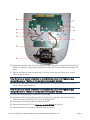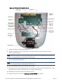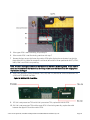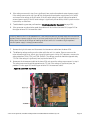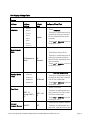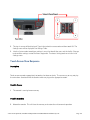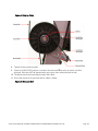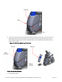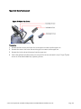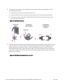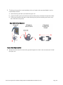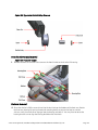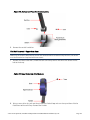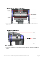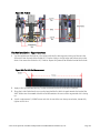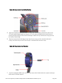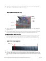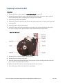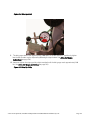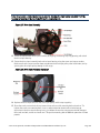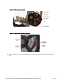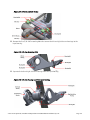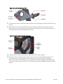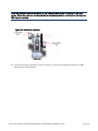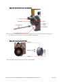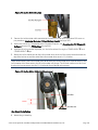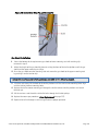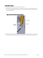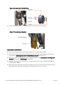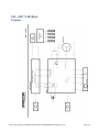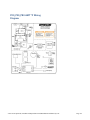
1
Service Manual AMT 885, 835, 833, 823 Open Stride and Fixed 20039-172 PRECOR CUSTOMER SUPPORT © Precor Incorporated, Unauthorized Reproduction and Distribution Prohibited by Law Page 1 Contents About This Document .............................................................................................. 7 Acrobat Reader Users: .......................................................................................................... 7 Things you should know .......................................................................................... 8 Right, Left, Front, and Back Conventions .....................................................................................................................8 General System Information............................................................................................................................................9 Warning and Caution Statements and General Safety Guidelines....................................................................... 9 Safety.................................................................................................................................................................................... 10 General Information ......................................................................................................................................................... 10 Tools Required .................................................................................................................................................................... 11 P30 Console ............................................................................................................... 12 Accessing the P30 Diagnostic Software .................................................................................................................... 13 Procedure: ............................................................................................................................. 13 P30 Diagnostic Software Menu Table .............................................................................. 14 Displaying P30 Information ........................................................................................................................................... 19 Procedure .............................................................................................................................. 19 P30 Information Table .......................................................................................................... 20 Setting the P30 Club Parameters ................................................................................................................................ 24 P30 Setting Club Parameters Table .................................................................................. 24 Documenting P30 Software Problems ...................................................................................................................... 27 Replacing the Upper PCA .............................................................................................................................................. 28 Replacing the P30 Metrics PCA .................................................................................................................................. 34 Replacing the P30 HR PCA ........................................................................................................................................... 36 Flash Programming the Upper PCA ........................................................................................................................... 38 Upload Procedure ............................................................................................................... 38 P30 Troubleshooting .............................................................................................. 39 Troubleshooting the Keypad and Upper PCA ......................................................................................................... 39 Procedure .............................................................................................................................. 39 Troubleshooting the Handheld Heart Rate .............................................................................................................. 42 Circuit Description ................................................................................................................ 42 Normal hand held reading - No chest strap reading ................................................... 42 No hand held reading - Normal chest strap reading ................................................... 43 No hand held reading - No chest strap reading ........................................................... 44 P30 AMT '11 - Upper Display does not Illuminate ................................................................................................. 44 P80 Console ..............................................................................................................47 P80 Settings ...................................................................................................................................................................... 48 P80 Settings Table ................................................................................................................. 50 P80 About........................................................................................................................................................................... 51 About P80 Table ................................................................................................................... 52 P80 Equipment Usage .................................................................................................................................................... 54 P80 Equipment Usage Table .............................................................................................. 55 © Precor Incorporated, Unauthorized Reproduction and Distribution Prohibited by Law Page 1 P80 System Settings ....................................................................................................................................................... 55 P80 System Settings Table ................................................................................................... 57 Updating P80 Software.................................................................................................................................................. 58 P80 System Tests ............................................................................................................................................................ 60 P80 System Test Table .......................................................................................................... 61 P80 Connectivity ............................................................................................................................................................. 64 P80 Connectivity Settings Table ........................................................................................ 65 P80 Connectivity Set Up and Registration Procedure .................................................. 66 P80 Display ........................................................................................................................................................................ 71 P80 Display Settings Table................................................................................................... 72 P80 TV Settings ............................................................................................................................................................... 73 Channel Guide ..................................................................................................................... 75 To scan for available channels: ........................................................................................ 75 To name a channel: ............................................................................................................ 75 To delete a channel from the Channel Guide: ............................................................. 75 P80 Workout Limits........................................................................................................................................................ 76 P80 Workout Limits Table ..................................................................................................... 77 Manage P80 Settings (Cloning) .................................................................................................................................. 79 P80 Cloning Settings Table ................................................................................................. 79 P80 Cloning Procedure ....................................................................................................... 80 Replacing the P80 Console ........................................................................................................................................... 84 Console Mounting - Removal ............................................................................................ 84 Disconnection Cables ......................................................................................................... 85 Console Hook and Notch ................................................................................................... 86 Cable Connections ............................................................................................................. 87 Console Mounting - Install .................................................................................................. 90 Replacing the P80 Heart Rate PCA Board ................................................................................................................ 90 P80 Troubleshooting ............................................................................................. 94 Black Screen - TV Only .................................................................................................................................................. 94 Description ............................................................................................................................. 94 Possible Causes..................................................................................................................... 94 Possible Remedies ................................................................................................................ 95 Black Screen - Full Console ........................................................................................................................................... 96 Description ............................................................................................................................. 96 Possible Causes..................................................................................................................... 96 Possible Remedies ................................................................................................................ 96 Boot Screen Procedure ....................................................................................................... 97 Poor Quality Video - Single Unit Only ....................................................................................................................... 97 Description ............................................................................................................................. 97 Possible Causes..................................................................................................................... 97 Possible Remedies ................................................................................................................ 98 Poor Quality Video - All Units ...................................................................................................................................... 98 Description ............................................................................................................................. 98 Possible Causes..................................................................................................................... 98 Possible Remedies ................................................................................................................ 99 © Precor Incorporated, Unauthorized Reproduction and Distribution Prohibited by Law Page 2 Poor Quality Video - One Channel or Limited Channels ...................................................................................... 99 Green Screen ................................................................................................................................................................... 100 Description ........................................................................................................................... 100 Possible Causes................................................................................................................... 100 Stuttering Channels........................................................................................................................................................ 101 Description ........................................................................................................................... 101 Possible Causes................................................................................................................... 101 Possible Remedies .............................................................................................................. 101 Touch Screen Unresponsive ........................................................................................................................................ 101 Description ........................................................................................................................... 101 Possible Causes................................................................................................................... 101 Possible Remedies .............................................................................................................. 102 Single Secret Handshake Procedure.............................................................................. 102 Procedure ............................................................................................................................ 102 Touch Screen Slow Response .................................................................................................................................... 103 Description ........................................................................................................................... 103 Possible Causes................................................................................................................... 103 Possible Remedies .............................................................................................................. 103 Touch Screen Responses Incorrectly to Touch ..................................................................................................... 104 Description ........................................................................................................................... 104 Possible Causes................................................................................................................... 104 Possible Remedies .............................................................................................................. 104 Single Secret Handshake Procedure.............................................................................. 104 Procedure ............................................................................................................................ 104 Poor Audio Quality – All Channels, One/Limited Units ..................................................................................... 105 Description ........................................................................................................................... 105 Possible Causes................................................................................................................... 105 Possible Remedies .............................................................................................................. 106 Poor Audio Quality – All Channels, Multiple Units .............................................................................................. 106 Description ........................................................................................................................... 106 Possible Causes................................................................................................................... 106 Possible Remedies .............................................................................................................. 106 Machine Controls Unresponsive ............................................................................................................................... 107 Description ........................................................................................................................... 107 Possible Causes................................................................................................................... 107 Possible Remedies .............................................................................................................. 107 Machine Controls Incorrect Response .................................................................................................................... 108 Description ........................................................................................................................... 108 Possible Causes................................................................................................................... 108 Possible Remedies .............................................................................................................. 108 Message Out of Service Displayed ........................................................................................................................... 109 Description ........................................................................................................................... 109 Possible Causes................................................................................................................... 109 Possible Remedies .............................................................................................................. 109 Message Please Reset the Treadmill Displayed .................................................................................................... 110 Description ........................................................................................................................... 110 Possible Causes................................................................................................................... 110 Possible Remedies .............................................................................................................. 110 © Precor Incorporated, Unauthorized Reproduction and Distribution Prohibited by Law Page 3 Unit reboots of its own volition.................................................................................................................................... 111 Description ........................................................................................................................... 111 Possible Causes................................................................................................................... 111 Possible Remedies .............................................................................................................. 111 Checking the AMT Operation ............................................................................. 113 Checking AMT Operation .............................................................................................................................................113 Procedure ............................................................................................................................ 113 Inspection and Adjustment Procedures .......................................................... 115 Measuring the Resistance of a Generator ................................................................................................................115 Procedure ............................................................................................................................ 115 Inspecting and Adjusting the H-brake Belt Tension ............................................................................................. 116 Procedure ............................................................................................................................ 116 Inspecting and Adjusting the Generator Belt Tension ......................................................................................... 118 Procedure ............................................................................................................................ 118 Inspecting and Adjusting the Drive Input Belt Tension ....................................................................................... 119 Procedure ............................................................................................................................ 119 Calibrating the Incline Motor ...................................................................................................................................... 123 Procedure ............................................................................................................................ 123 Drive Belt Gauge Instructions .....................................................................................................................................126 Preventive Maintenance ...................................................................................... 128 Regular Preventive Maintenance (Owner) .............................................................................................................128 After Each Use .................................................................................................................................................................128 Daily Maintenance .........................................................................................................................................................128 Weekly Maintenance ....................................................................................................................................................129 Quarterly Maintenance .................................................................................................................................................129 On-Site Preventive Maintenance (Service Technician) ..................................................................................... 130 AMT Base Troubleshooting Procedures .......................................................... 131 Troubleshooting the Generator .................................................................................................................................. 132 Troubleshooting the Incline System .......................................................................................................................... 133 Troubleshooting the Interconnect Cable ................................................................................................................. 135 AMT Base Replacement Procedures ................................................................ 136 Cover Replacement ........................................................................................................................................................ 137 Top Cover Removal ........................................................................................................... 137 Front Cover Removal......................................................................................................... 138 Center Beam Cover Removal ......................................................................................... 139 Back Cover Removal ........................................................................................................ 140 Left and Right Side Cover Removal ............................................................................... 141 Left and Right Side Bottom Cover Removal ................................................................. 141 Left and Right Bottom Cover Assembly ......................................................................... 142 Left and Right Side Cover Assembly .............................................................................. 142 Back Cover Assembly........................................................................................................ 143 Center Beam Cover Assembly ........................................................................................ 144 © Precor Incorporated, Unauthorized Reproduction and Distribution Prohibited by Law Page 4 Front Cover Assembly ........................................................................................................ 144 Upper Arm Cover Replacement ..................................................................................... 145 Rear Flat Belt Terminal Cover Replacement ................................................................. 146 Upper Arm Cam Cover Replacement........................................................................... 147 Top Cover Assembly .......................................................................................................... 147 Replacing a Belt Guard ................................................................................................................................................. 148 Finger Guard Replacement Procedure ......................................................................... 148 Replacing the Upper Arm Grip.....................................................................................................................................151 Upper Arm Grip Replacement Procedure .................................................................... 151 Replacing a Flat Belt Terminal .....................................................................................................................................156 Flat Belt Terminal Replacement Procedure .................................................................. 156 Rear Flat Belt Terminal Cover Removal .......................................................................... 156 Replacing a Upper Arm Flat Belt Pulley ................................................................................................................... 160 Upper Arm Flat Belt Pulley Replacement Procedure .................................................. 160 Replacing a Stairarm Pedal ......................................................................................................................................... 166 Stairarm Pedal Replacement Procedure ...................................................................... 166 Replacing a Stairarm ......................................................................................................................................................167 Stairarm Replacement Procedure .................................................................................. 168 Rear Flat Belt Terminal Cover Removal .......................................................................... 168 Replacing the Flat Belts ................................................................................................................................................. 173 Belt Replacement & Odometer Tracking Codes......................................................... 175 Inside Flat Belt Replacement ........................................................................................... 176 Outside Flat Belt Replacement........................................................................................ 183 Rear Flat Belt Terminal Cover Removal .......................................................................... 186 Replacing the Front Arm Assemblies - With Flat Belts and Press Fit Cams (After 4/3/2013).............. 198 Rear Flat Belt Terminal Cover Removal .......................................................................... 199 Front Flat Belt Terminal Removal ..................................................................................... 201 Replacing a Front Arm Assembly - Without Flat Belts and Non-Press Fit Cams. (Prior to 4/3/2013) 210 Front Arm and Cam Replacement Procedure ............................................................ 210 Replacing the Lower Board .........................................................................................................................................224 Removing the Lower PCA Cover .................................................................................... 224 Removing the Lower PCA ................................................................................................ 224 Replacing the Lower PCA and Battery Bracket ..................................................................................................... 225 Procedure ............................................................................................................................ 225 Replacing the Battery.................................................................................................................................................... 227 Procedure ............................................................................................................................ 227 Replacing the Generator Belt......................................................................................................................................228 Procedure ............................................................................................................................ 228 Replacing the Generator ............................................................................................................................................... 231 Procedure ............................................................................................................................ 231 Replacing the Drive Input Pulley Belt ....................................................................................................................... 233 Drive Input Pulley Belt Replacement Procedure .......................................................... 233 Replacing the Step Up Pulley ...................................................................................................................................... 237 Procedure ............................................................................................................................ 237 Replacing the Crank Arm.............................................................................................................................................242 Crank Arm Replacement Procedure ............................................................................. 242 Replacing the Drive Input Pulley ...............................................................................................................................245 Procedure ............................................................................................................................ 245 © Precor Incorporated, Unauthorized Reproduction and Distribution Prohibited by Law Page 5 Replacing the Lift Arm Housing .................................................................................................................................254 Lift Arm Housing Replacement Procedure .................................................................... 254 Replacing the drive input housing .............................................................................................................................269 Drive Input Housing Replacement Procedure ............................................................. 269 Replacing a Tie Rod .......................................................................................................................................................286 Procedure ............................................................................................................................ 286 Replacing the Stride Dial Sensor ...............................................................................................................................287 Procedure ............................................................................................................................ 287 Replacing the H-Brake Belt .........................................................................................................................................288 Procedure ............................................................................................................................ 289 Replacing the H-Brake Cam Assembly................................................................................................................... 290 Procedure ............................................................................................................................ 291 Replacing the H-Brake Drum Assembly.................................................................................................................. 295 Procedure ............................................................................................................................ 295 Replacing the Gas Shock .............................................................................................................................................302 Replacing the Gas Shock ................................................................................................. 302 Replacing the Incline Motor ........................................................................................................................................305 Procedure ............................................................................................................................ 305 Wiring Diagrams .................................................................................................... 310 P30 - AMT '11 835 Block Diagram ..............................................................................................................................311 P20_P30_P80 AMT '11 Wiring Diagram ................................................................................................................. 312 Index ............................................................................................................................. 15 © Precor Incorporated, Unauthorized Reproduction and Distribution Prohibited by Law Page 6 Section One About This Document Warning: This service manual is for use by Precor trained service providers only. If you are not a Precor Trained Servicer, you must not attempt to service any Precor Product; Call your dealer for service. This document contains information required to perform the majority of troubleshooting, and replacement procedures required to repair and maintain this product. This document contains general product information, software diagnostic procedures (when available), preventative maintenance procedures, inspection and adjustment procedures, troubleshooting procedures, replacement procedures and electrical block and wiring diagrams. Acrobat Reader Users: To move directly to a procedure, click the appropriate procedure in the bookmark section to the left of this page. You may drag the separator bar between this page and the bookmark section to change the size of the page being viewed. © Precor Incorporated, Unauthorized Reproduction and Distribution Prohibited by Law Page 7 Section Two Things you should know In This Section Right, Left, Front, and Back Conventions.................................................................. 8 General System Information........................................................................................ 9 Warning and Caution Statements and General Safety Guidelines ................... 9 Safety ................................................................................................................................. 10 General Information....................................................................................................... 10 Tools Required ................................................................................................................ 11 Right, Left, Front, and Back Conventions In this manual, right, left, front, and back are from the perspective of a user standing on the AMT facing the console display. Figure 1: Front, Back, Left, Right Conventions © Precor Incorporated, Unauthorized Reproduction and Distribution Prohibited by Law Page 8 General System Information The generator performs three functions in the AMT. First, by controlling the amount of electrical current applied from the generator to a load circuit, the user’s pedaling resistance is controlled. Second, the generator is used to charge the AMT’s internal battery. Lastly, one of the generators three phase output windings is monitored to determine when the unit is in use and when it is idle. This system also determines the step rate by determining the operating speed (output frequency) of the monitored generator winding. There is also a magnetic brake that applies resistance to horizontal motion and a sensor that measures horizontal motion (stride length). Warning and Caution Statements and General Safety Guidelines Warning statements indicate a particularly dangerous activity. Warning statements you will find in this manual include: ♦ Because this is a self powered unit, it will either be necessary to either equip the unit with the optional external power supply or have an assistant pedal on the unit while voltage measurements are being taken. Because of the danger of working on the unit while it is in motion using the optional external power supply is strongly recommended. ♦ When the unit is used, stairarms are in motion; the generator will operate and produce potentially hazardous voltages even when the battery is disconnected. ♦ Caution statements are intended to prevent damage to the AMT as a result of the current activity. Caution statements included in this manual are listed below: When it is necessary to lift or move the AMT, ensure that the AMT has adequate support and that you use proper lifting techniques. When the rear platform is removed, the AMT may be lifted from the rear and moved like a wheelbarrow. To remove power from the AMT, the optional external power supply (when equipped) must be disconnected from the wall outlet and the red (positive) wire must be disconnected from the battery. Always ensure that the AMT external power supply is unplugged from the wall outlet and the red (positive) wire is removed from the battery when you inspect or adjust the AMT, or when you isolate, remove, or replace an AMT component. Removing the covers exposes high voltage components and potentially dangerous machinery. Exercise extreme caution when you perform maintenance procedures with the cover(s) removed. During service operations you will be very close to moving machinery and voltage bearing components. When you perform maintenance procedures with the covers removed, remove jewelry (especially from ears and neck), tie up long hair, remove neck ties, and do not wear loose clothing. Exercise caution when touching any wire or electrical component during AMT operation. © Precor Incorporated, Unauthorized Reproduction and Distribution Prohibited by Law Page 9 A pinching hazard exists when the unit is operated. It is possible to seriously pinch a finger. The AMT can be mechanically locked by inserting a screwdriver through the primary sheave and frame. See the illustration below. Locking the AMT will prevent accidental pinching. A pinching hazard exists when the unit is operated. It is possible to seriously pinch a finger. The AMT can be made immobile by lift the stairarm pedals and removing the tension from stairarm flat belts. Removing the tension from the flat belts will prevent accidental pinching. Safety Safety guidelines you should know and follow include: ♦ Read the owner’s manual and follow all operating instructions. ♦ Operate the AMT on a solid, level surface with the unit properly leveled. The AMT is properly leveled when all five feet are in contact with the floor. Visually check the AMT before beginning service or maintenance operations. If it is not completely assembled or is damaged in any way, exercise extreme caution while operating and checking the AMT. ♦ When operating the AMT, do not wear loose clothing. Do not wear shoes with heels or leather soles. Check the soles of your shoes and remove any embedded stones. Tie long hair back. ♦ Do not rock the unit. Do not stand or climb on the handlebars, display enclosure, or cover. ♦ Do not set anything on the handlebars, display enclosure, or cover. Never place liquids on any part of the AMT, while performing service. ♦ To prevent electrical shock, keep all electrical components away from water and other liquids. ♦ Do not use accessory attachments that are not recommended by the manufacturer-such attachments might cause injuries. ♦ AMT’s equipped with Cardio Theater PVS units will have external power supply and coaxial cable routed through the bottom of the unit to the top of the display console. Cord management must be maintained. General Information For the latest exploded view, part number and part pricing information, visit the Precor dealer website at www.precor.com/connection. © Precor Incorporated, Unauthorized Reproduction and Distribution Prohibited by Law Page 10 Tools Required Multimeter US and metric end wrench set Allen wrench set US and metric socket wrench set Anti-static kit Torque wrench, 200 in./lbs. Screwdriver set Torque wrench, 200 ft./lbs OTC 6673 Universal Belt Tension Gauge 4 - 6 gear puller © Precor Incorporated, Unauthorized Reproduction and Distribution Prohibited by Law Page 11 Section Three P30 Console In This Section Accessing the P30 Diagnostic Software .................................................................. 13 Displaying P30 Information ......................................................................................... 19 Setting the P30 Club Parameters ............................................................................... 24 Documenting P30 Software Problems ..................................................................... 27 Replacing the Upper PCA ............................................................................................. 28 Replacing the P30 Metrics PCA ................................................................................. 34 Replacing the P30 HR PCA .......................................................................................... 36 Flash Programming the Upper PCA........................................................................... 38 © Precor Incorporated, Unauthorized Reproduction and Distribution Prohibited by Law Page 12 Accessing the P30 Diagnostic Software The P30 Console diagnostic software consists of the following modes: ♦ Display Test ♦ Keyboard Test ♦ Heart Rate Test ♦ Brake Test ♦ RPM Test ♦ Battery Test ♦ Stride Position Test Procedure: Figure 2: P30 Software Access 1 The AMT 885, 835, 833, and 832 uses the standard access codes to provide access to the various software features. Use the PAUSE key and the numeric keypad to enter the access code. The standard access codes use all sequential key presses. The allowable delay between key presses is short. If too much time is taken between key presses or the wrong key is pressed the access procedure will be aborted. If the access is aborted, it will be necessary to start over from the beginning. 2 See P30 Diagnostic Software Menu Table (on page 14). © Precor Incorporated, Unauthorized Reproduction and Distribution Prohibited by Law Page 13 P30 Diagnostic Software Menu Table Test Type Action Descriptions Press keys Hardware Validation will scroll across the display PAUSE,5,1,7,6,5,7, followed by DISPLAY TEST. 6,1, sequentially. Display Test Press OK key The upper most group of LED’s will illuminate on the display. Check the display to ensure that all LED segments are illuminated. Press the OK key four more times To display the remaining LED groups. Check each display group to ensure that all LED segments are illuminated. Press the CLEAR key to return to Hardware Validation Press the key KEYBOARD TEST will scroll across the display Press the OK key A representation of all of the keys on the console will be displayed. Pressing a key on the console will cause the illuminated representation of that key to turn off. Press all of the keys on the console to ensure that all of the keys are functioning. Keyboard Test Press and hold the CLEAR key for 5 seconds to return to Hardware Validation Press the key Heart Rate Test Press the OK key HEART RATE will be displayed. Grasp both of the heart rate grips on the handlebar, after a couple of seconds the heart rate will be displayed in the heart rate and smart rate displays. Use chest strap transmitter or a test transmitter to © Precor Incorporated, Unauthorized Reproduction and Distribution Prohibited by Law Page 14 test the wireless heart rate function, after a couple of seconds the heart rate will be displayed in the heart rate and smart rate displays. Press the CLEAR key to return to Hardware Validation Press the key BRAKE will be displayed. Press the OK key The console will display the power bits (PWRB). Changing the resistance , keys will change the power bit settings. Brake Test Press the CLEAR key to return to Hardware Validation Press the key RPM will be displayed. The console will display the Pulse. The pulse is showing a count of zero crossings from the generator. RPM shows a software averaged version of pulse. Press the OK key RPM Test Use p,q keys to view the following RPM readings. ♦ PULSE ♦ MIN ♦ MAX Press the CLEAR key to return to Hardware Validation Battery Test Press the key BATTERY will scroll across the display. Press the OK key The console will display the battery test. Battery test will display battery voltage. Press the CLEAR key to return to Hardware Validation Press the CLEAR STRIDE POSITION TEST will scroll across the © Precor Incorporated, Unauthorized Reproduction and Distribution Prohibited by Law Page 15 key to return to Hardware Validation Stride Position Test Press the key display. The low, high and actual stride positions will be displayed. The low display shows the lowest position reading achieved during the test. The high display shows the highest position reading achieved during the test. The actual display changes with the current stride position. Stride on the AMT to the maximum horizontal movement in both directions. At maximum stride length the low stride display should read 0 and the high stride display should read 40. Press the OK key Press the CLEAR key to return to Hardware Validation Vertical Position Test Press the key VERTICAL POSITION TEST will scroll across the display. Press the OK key Displays a digital representation of vertical movement of the stairarms. Press the CLEAR key to return to Hardware Validation Press the key Stride Count Reset Press the OK key. STRIDE COUNT RESET will scroll across the display. When STRIDE COUNT RESET is selected, CONTINUE PEDALING, AND PRESS OK TO RESET BELT STRIDE COUNT will scroll across the display. Note: The STRIDE COUNT RESET is used to CLEAR the stride count to zero only when the support belts are replaced. © Precor Incorporated, Unauthorized Reproduction and Distribution Prohibited by Law Page 16 If the OK key is pressed, the software executes the following steps. 1 Clears the LPCA belt stride count to zero. 2 Increments the LPCA value to show how many times Press the OK key the belt has been replaced. to CLEAR the stride 3 Log the odometer into LPCA with the stride count of count. the last belt replacement. Or 4 Clears the UPCA belt stride count to zero. Press the CLEAR 5 Increments the UPCA value to show how many times the belt has been replaced. key to cancel the Stride Count Reset 6 Log the odometer into UPCA with the stride count of and return to the last belt replacement. Hardware Validation. Note: If power is lost or the unit is no longer being pedaled during the rest process, the update process will be interrupted, displaying a error 70 (Belt replacement, LPCA not read). If a error is displayed, the Stride Count Reset process must be repeated. Press the CLEAR key to return to Hardware Validation Incline/Crossra Press the key mp Incline/ Crossramp will be displayed. © Precor Incorporated, Unauthorized Reproduction and Distribution Prohibited by Law Page 17 Two numbers will be displayed, the percent of lift and A/D number related to the current lift position. The A/D (analog to digital) number represents the lift potentiometer reading. The A/ D number will be in the range of 0 to 255 or 0 to 32769. Press the OK key The lift may be operated using the INCLINE/CROSSRAMP keys. The incline percentage and A/D numbers will change accordingly. Care must be taken while operating the lift in this mode because the normal upper and lower range limits are not in effect. It is possible to operate the lift to its physical limits and may cause the lift motor to jam. Press the CLEAR key to return to Hardware Validation Press the PAUSE/RESET key to exit the Hardware Validation tests. © Precor Incorporated, Unauthorized Reproduction and Distribution Prohibited by Law Page 18 Displaying P30 Information The information display will access the following data: ♦ Odometer ♦ Hour Meter ♦ U-Boot Software ♦ U-Base Software ♦ Lower Software ♦ Metrics Board Software ♦ Stride Dial Software ♦ Serial Number ♦ Usage log ♦ Error Log Procedure 1 The AMT 885, 835, 833, and 832 uses the standard access codes to provide access to the various software features. Use the PAUSE key and the numeric keypad to enter the access code. The standard access codes use all sequential key presses. The allowable delay between key presses is short. . If too much time is taken between key presses or the wrong key is pressed the access procedure will be aborted. If the access is aborted, it will be necessary to start over from the beginning. 2 See, P30 Informations Table (see "P30 Information Table" on page 20). © Precor Incorporated, Unauthorized Reproduction and Distribution Prohibited by Law Page 19 P30 Information Table Displayed Information Action Description With the PRECOR banner scrolling, press the keys PAUSE,6,5, sequentially. DIAGS _ INFORMATION will scroll across the display. Followed by BELT USAGE. Diagnostics Information Use the , keys to move to the desired display shown in the list above. BELT STRIDE COUNT XXXXXX STRIDES will be displayed, followed by STRIDE COUNT RESETS XX RESETS, and then ODOMETER AT LAST RESET XXXXXX MILES. Press the OK key. Belt Usage ♦ BELT STRIDE COUNT shows the number of strides on the current belt. ♦ STRIDE COUNT RESET shows the number of strides at the time of last belt reset. ♦ ODOMETER AT LAST RESET shows the number of miles at the time of the last belt reset. Press the CLEAR key to exit the Belt Usage display. Use the , keys to move to move to Odometer. © Precor Incorporated, Unauthorized Reproduction and Distribution Prohibited by Law Page 20 The odometer will display HORIZONTAL distance in miles or KM depending on Club parameter settings and VERTICAL distance in steps. Press the OK key. Note: The odometer data is stored in non-volatile memory on the upper PCA. If the upper PCA is replaced the odometer data will be lost. Odometer Press the CLEAR key to exit the odometer display. Use the , keys to move to move to HOUR METER. Hour Meter Press the OK key. The operating time of the unit will be displayed as 12345 HOURS. The operating time is defined as total amount of time that the unit has operated in program modes. The hour meter is also used to provide the time stamp for the error code log. Press the CLEAR key to exit the HOUR METER display. Use the , keys to move to move to U-BOOT SW. U-Boot SW Press the OK key. The software part number will be displayed as XXXXX-XXX. Press the CLEAR key to exit the U-BOOT SW display. Use the , keys to move to move to HOUR METER. U-Base SW Press the OK key. The software part number will be displayed as XXXXX-XXX. Press the CLEAR key to exit the U-BASE SW display. © Precor Incorporated, Unauthorized Reproduction and Distribution Prohibited by Law Page 21 Use the , keys to move to move to LOWER SW. Press the OK key. Lower SW The software part number will be displayed as XXXXX-XXX. Press the CLEAR key to exit the LOWER SW display. Use the , keys to move to move to METRICS BOARD SW. Metrics Board SW Press the OK key. The software part number will be displayed as XXXXX-XXX. Press the CLEAR key to exit the Metrics BOARD SW display. Use the , keys to move to move to STRIDE DIAL SW. Stride Dial SW Press the OK key. The software part number will be displayed as XXXXX-XXX. Press the CLEAR key to exit the STRIDE DIAL SW display. Use the , keys to move to move to SER. NUMBER. Serial Number Press the OK key. The serial number will be displayed. The serial number may be incorrect or not displayed if the upper PCA has been replaced. Press the CLEAR key to exit the SER. NUMBER display. © Precor Incorporated, Unauthorized Reproduction and Distribution Prohibited by Law Page 22 Use the , keys to move to move to USAGELOG. Press the OK key. Usage log A message will scroll describing the program, the number of times and the number of minutes the program was used. Use the , keys to move through the list of programs Press the CLEAR key to exit the USAGELOG display. Use the , keys to move to move to ERROR LOG. Press the OK key. The quantity of errors in the log will be displayed. Press the OK key. The most recent error will be displayed first. Use the , keys to move through the list of errors. The error messages will list the error name, the odometer reading when the error occurred and the hour meter when the error occurred. The message HOLD TO CLEAR ERRORS will be displayed. The error log will be cleared when the message NO ERRORS is displayed. Error Log If you wish to clear the error log, press and hold the Please note that the ERROR LOG may also be QUICK START key. accessed at any time by pressing and holding the CLEAR key for four seconds. If the error log does not contain any errors, the message STUCK KEY will be displayed. Press the CLEAR key to exit the ERROR LOG display. Press the PAUSE key to exit the DIAGSINFORMATION DISPLAY. © Precor Incorporated, Unauthorized Reproduction and Distribution Prohibited by Law Page 23 Setting the P30 Club Parameters This procedure allows you to change the following club settings: ♦ Select Language ♦ Select Units ♦ Set Max Workout Time ♦ Set Max Pause Time ♦ Set Cool Down Time Procedure 1 The AMT 885, 835, 833, and 832 uses the standard access codes to provide access to the various software features. Use the PAUSE key and the numeric keypad to enter the access code. The standard access codes use all sequential key presses. The allowable delay between key presses is short. . If too much time is taken between key presses or the wrong key is pressed the access procedure will be aborted. If the access is aborted, it will be necessary to start over from the beginning. 2 See P30 Setting Club Parameters Table (on page 24). P30 Setting Club Parameters Table Setting Action Description Club Settings With the banner scrolling, press keys PAUSE,5,6,5,1,5,6,5, sequentially. DIAGS-SET CLUB PARAMETERS will scroll across the display followed by select LANGUAGE. Press the OK key. A list of available languages will be displayed, including Set Language Use the , keys to toggle between the available languages. ♦ ENGLISH ♦ DEUTSCH ♦ ESPANOL ♦ FRANCAIS ♦ NEDERLANDS ♦ PORTUGUES ♦ RUCCKIJI © Precor Incorporated, Unauthorized Reproduction and Distribution Prohibited by Law Page 24 ♦ ITALIANO Note: When the default language is changed to anything other than English, the submenus will remain in English. Press the OK key to select UNITS will be displayed. desired language and exit to Club Settings. Press the OK key. Set Units Use the , keys to toggle between U.S and METRIC. U.S (miles per hour) and METRIC (kilometers per hour) will be displayed. Press the OK key to select desired unit exit to Club Settings. SET MAX WORKOUT TIME will be displayed. Press the OK key. Set Max Workout Time Use the , keys to select the maximum time a user can remain in a program. Press the OK key to save selection and exit to Club Settings. As the , keys are pressed, the displayed value increments or decrements between 1 and 240 minutes, and NO LIMIT. If an arrow key is held down then the value changes slowly at first and then at an increasing rate. SET MAX PAUSE TIME will be displayed. Press the OK key. Set Max Pause Time Use the , keys to select the maximum time the unit will remain in paused before resetting. Press the OK key to save selection and exit to Club Settings. As the , keys are pressed, the displayed value increments or decrements between 1 and 120 seconds. If an arrow key is held down then the value changes slowly at first and then at an increasing rate. SET COOL DOWN TIME will be displayed. Press the OK key. Set Cool Down Time Use the , keys to select the cool down time. As the , keys are pressed, the displayed value increments or decrements between 0 and 5 minutes. © Precor Incorporated, Unauthorized Reproduction and Distribution Prohibited by Law Page 25 Press the OK key to save selection and exit to Club Settings. SET METRIC DEFAULTS will be displayed. Press the , keys. A list of available default settings will be displayed, including: Set Metric Defaults Use the , keys to select the default settings that will be displayed during a workout. Press the OK key to save selection and exit to Club Settings. ♦ OFF ♦ % COMPLETE ♦ TIME IN ZONE ♦ SEGMENT TIME REMAINING ♦ AVERAGE SPEED ♦ CALS/MIN ♦ CALS/HR ♦ WATTS ♦ METS ♦ TARGET HR ♦ AVE HEART RATE ♦ SHOW ALL CROSSRAMP AUTO-LEVEL will be displayed. Press the OK key. Set Crossramp Auto-Level Use the , keys to select height the crossramp will return to when after a workout. As the , keys are pressed, the displayed value increments or decrements between XRAMP 1 and 120 seconds. If an arrow key is held down then the value changes slowly at first and then at an increasing rate. Press the OK key to save selection and exit to Club Settings. HIDDEN PROGRAMS will be displayed. Press the OK key. Set Hidden Programs A list of available default settings will be displayed, including: Use the , keys to select the either Show Programs or ♦ SHOW PROGRAMS Hide Programs. ♦ HIDE PROGRAMS © Precor Incorporated, Unauthorized Reproduction and Distribution Prohibited by Law Page 26 Press the OK key to save selection and exit to Club Settings. SET CUSTOM PROGRAMS will be displayed. Press the OK key. Set Custom Programs Pressing the , keys changes the active column. Pressing the corresponding , resistance keys changes the resistance value for that column. When this function is initiated, the currently stored custom program (#1 or #2) is displayed in the matrix. The first column is active; all the LEDs in that column blink. The resistance value for that column is displayed in the message bar. Press the OK key to save program and exit to Club Settings. Press the PAUSE key exit Club Settings. Documenting P30 Software Problems When a problem is found with the software in the upper or lower PCA, record the information listed below. When a problem occurs, record the following information: ♦ Model and serial number ♦ Software version number ♦ Program number running when the problem occurred A description of: ♦ What happened or failed to happen. ♦ The action taken by the user just before the problem occurred. ♦ Problem-related information (such as how far into the program the problem occurred, the work level being used when the problem occurred, error code displayed, etc.). ♦ The frequency of occurrence. © Precor Incorporated, Unauthorized Reproduction and Distribution Prohibited by Law Page 27 Replacing the Upper PCA 1 Set the treadmill circuit breaker in the off position and unplug the treadmill’s line cord from the AC outlet. (TRM only) 2 The PCA’s in the console are static sensitive. They can be damaged if proper static prevention equipment is not used. Attach an anti-static wrist strap to your arm, and then connect the ground lead of the wrist strap to the treadmill’s frame ground. 3 Remove the two screws that fasten the dash transition cover and remove the cover. Figure 3: Dash Transition Cover – (TRM only) 4 Remove the four screws that fasten the console to the dash mounting plate. Figure 4: Console Mounting Plate © Precor Incorporated, Unauthorized Reproduction and Distribution Prohibited by Law Page 28 5 Remove the two screws that fasten the access panel to the console. Figure 5: Console Access Panel 6 Remove the back access Panel: a) Treadmills: Lift the console off the maintenance hook and then position the console so that the back panel is accessible and remove the back cover. b) AMT’s, EFX’s, CLM’s, UBK’s, and RBK’s: Tilt the console forward on the maintenance access hook on the dash weldment and remove the back. Figure 6: Maintenance Access Hook 7 Remove the Heart Rate PCA. See Replacing the P30 HR PCA (on page 36). 8 Disconnect the Heart Rate Cable from the Heart Rate PCA. 9 Disconnect the Data cable, Auto Stop cable (Treadmill only), Stop Key cable (Treadmill only), Ground wire and the CSAFE cable (if in use) from the Upper PCA. Remove the console from the maintenance access hook and place it on a flat work surface. Figure 7: P30 Cable Connectors © Precor Incorporated, Unauthorized Reproduction and Distribution Prohibited by Law Page 29 10 Remove the two screws that fasten the back cover to the option cap and remove the cover. Figure 8: Option Cap Back Cover 11 Remove the 6 screws that fasten the rear cover from the console and remove. Figure 9: Rear Console Cover © Precor Incorporated, Unauthorized Reproduction and Distribution Prohibited by Law Page 30 12 Disconnect the Metric cable (J5), Machine Controls cable (J4), Option Cap cable (J6, if applicable), Keypad Metric cable (J2) and HR cable (J10) from the Upper PCA board. 13 Remove the five screws that fasten the Upper PCA board to the console and remove the Upper. Figure 10: P30 Upper PCA & Metric Board © Precor Incorporated, Unauthorized Reproduction and Distribution Prohibited by Law Page 31 14 Install the replacement upper PCA into the console using the five screws removed in step 14. Torque to 10 inch pounds. Note: Do not use an electric screw driver or over tighten the screws. Over tightening may damage the console. This type of damage is not covered under warranty. 15 The white wire in the Metrics cable and the yellow wire in the Machine Controls and HR cables indicate pin 1. Align the white wire in the Metrics cable and yellow wires in the Machine Controls and HR cables with the pin 1 markings on the upper PCA. Note: If pin 1 is not marked on the Upper PCA refer to the pin 1 reference below. Figure 11: P30 PCA - Pin 1 Reference © Precor Incorporated, Unauthorized Reproduction and Distribution Prohibited by Law Page 32 16 Reconnect the Metric cable (J5), Metric cable (J1), Metric cable (J2), Machine Controls cable (J4), Option Cap cable (J6, if applicable), Keypad Metric cable and HR cable (J10) from the Upper PCA board. 17 Replace the P30 Rear Cover removed step 12 and secure the cover with the screws 6 screws. Torque to 10 inch pounds. Note: Do not use an electric screw driver or over tighten the screws. Over tightening may damage the console. This type of damage is not covered under warranty. 18 Replace the P30 Option Cap back cover removed step 11 and secure the cover with the screws 2 screws. Torque to 10 inch pounds. Note: Do not use an electric screw driver or over tighten the screws. Over tightening may damage the console. This type of damage is not covered under warranty. 19 Place the P30 console on the maintenance access hook. 20 Reconnect the Data cable, Auto Stop cable (Treadmill only), Stop Key cable (Treadmill only), Ground wire and the CSAFE cable (if in use) to the Upper PCA. 21 Reconnect the Heart Rate Cable to the Heart Rate PCA. 22 Replace the Heart Rate PCA. See Replacing the P30 HR PCA (on page 36). 23 Replace the access cover with the hardware removed in step 6. © Precor Incorporated, Unauthorized Reproduction and Distribution Prohibited by Law Page 33 24 Tilt the console back against the mounting plated. While tilting the console back feed the excess cable into weldment tube making sure that the cables will not become pinched. 25 Fasten the console to the dash mounting plate with the four screws removed in step 4. 26 Fasten the dash transition cover using the two screws removed in step 3. 27 Check treadmill operation as per procedure, Checking the AMT Operation (on page 113). Replacing the P30 Metrics PCA 1 Access the consoles upper PCA and Metric PCS as per procedure, Replacing the Upper PCA (on page 28). 2 Disconnect the Metric cable (J1) from the Metric PCA board. 3 Remove the four screws that fasten the Metric PCA board to the console and remove the Metric PCA and the four spacers. 4 Replace the four spacers removed in step 3 onto the console mounting studs. The spacers must be used to insure the Metrics LED’s are flush with the display window. If spacers are not used the Metrics LED’s will apply excessive pressure on the Metrics board and may cause damage to the Metrics board. 5 Install the replacement Metric PCA into the console using the four screws removed in step 3. 6 The white wire in the Metrics cables indicate pin 1. Align the white wire in the Metrics cables with the pin 1 markings on the Metrics PCA. © Precor Incorporated, Unauthorized Reproduction and Distribution Prohibited by Law Page 34 Figure 12: P30 Upper PCA & Metric Board 7 Connect the Metrics cable to the Metric PCA. 8 Replace the P30 Rear Cover removed step 11 and secure the cover with the screws 6 screws. Torque to 10 inch pounds. Note: Do not use an electric screw driver or over tighten the screws. Over tightening may damage the console. This type of damage is not covered under warranty. 9 Replace the P30 Option Cap back cover removed step 12 and secure the cover with the screws 2 screws. Torque to 10 inch pounds. Note: Do not use an electric screw driver or over tighten the screws. Over tightening may damage the console. This type of damage is not covered under warranty. 10 Place the P30 console on the maintenance access hook. 11 Reconnect the Data cable, Auto Stop cable (Treadmill only), Stop Key cable (Treadmill only), Heart Rate ground wire and the CSAFE cable (if in use) from the Upper PCA. 12 Reconnect the Heart Rate Cable to the Heart Rate PCA. 13 Replace the Heart Rate PCA. See Replacing the P30 HR PCA (on page 36). © Precor Incorporated, Unauthorized Reproduction and Distribution Prohibited by Law Page 35 14 Replace the access cover.. 15 Tilt the console back against the mounting plated. While tilting the console back feed the excess cable into weldment tube making sure that the cables will not become pinched. 16 Fasten the console to the dash mounting plate with the four screws. 17 Fasten the dash transition cover using the two screws (TRM only) 18 Check treadmill operation per Checking the AMT Operation (on page 113). Replacing the P30 HR PCA 1 Set the treadmill circuit breaker in the off position and unplug the treadmill’s line cord from the AC outlet. 2 The PCA’s in the console are static sensitive. They can be damaged if proper static prevention equipment is not used. Attach an anti-static wrist strap to your arm, and then connect the ground lead of the wrist strap to the treadmill’s frame ground. 3 Remove the HR PCA access panel on the back of the console. Figure 13: HR PCA Access Panel 4 The HR PCA snaps into its mounting. Press its tabs sideways and remove the HR PCA from its mounting. 5 Disconnect the HR cable and handlebar cable from the HR PCA. 6 Connect the HHHR Grip cable assembly to the upper connector on the HR PCA and the HR PCA Power cable to the lower connector on the replacement HR PCA. 7 Orient the replacement HR PCA so that the side with the protective foam pad is facing out and snap the HR PCA into its mounting. © Precor Incorporated, Unauthorized Reproduction and Distribution Prohibited by Law Page 36 Figure 14: HHHR Cable Assembly 8 Replace the HR PCA access panel removed in step 3. 9 Check treadmill operation per Checking the AMT Operation (on page 113). © Precor Incorporated, Unauthorized Reproduction and Distribution Prohibited by Law Page 37 Flash Programming the Upper PCA This unit utilizes an upper PCA software system that is capable of on site upper PCA software uploading (re-programming). The software upload may be accomplished with the use of a PDA (palm device) or a laptop computer. If a palm device is to be used it must use OS software version 3.2 or higher. Currently, we have only tested devices manufactured by Palm, but other manufacturer’s palm devices may also function correctly. If a palm device is to be used, the appropriate software must be available in the palm device. A PDA containing the appropriate software may be ordered from Precor or it may be downloaded to the PDA from your desktop or laptop computer via the hot sync function. With the PDA inserted in the hot sync cradle, download to Precor IFP (in field programmer) directory. If a laptop computer is to be used, the computer’s DB9 serial port will be used for the upload. Upload Procedure 1 The P30 must be powered down before the upload procedure can be initiated. Ensure that the P30 has not been used for a sufficient time to allow the lower PCA to completely discharge. The light emitting diode on the lower PCA will go out when the power supply is discharged. 2 If the CSAFE port is in use, temporarily disconnect the RJ-45 cable from the CSAFE port. If the CSAFE port is not in use, temporarily remove the plastic plug from the CSAFE port. 3 Connect the PDA or computer interface cable to the CSAFE port. 4 Select the software file to be uploaded on the palm device or computer. 5 Start pedaling the P30 or power up using the external power supply. When the P30 powers up the upload will commence. You must continue to pedal until the upload is complete, approximately 2 minutes. 6 Stop pedaling or disconnect the external power supply when the upload is complete, and allow the lower PCA to completely discharge. The light emitting diode on the lower PCA will go out when the power supply is discharged. 7 Start pedaling the P30, after it has been allowed to power down, the P30 will now be operating on the newly uploaded software. 8 Thoroughly, check the P30’s function per Checking the AMT Operation (on page 113). © Precor Incorporated, Unauthorized Reproduction and Distribution Prohibited by Law Page 38 Section Four P30 Troubleshooting In This Section Troubleshooting the Keypad and Upper PCA......................................................... 39 Troubleshooting the Handheld Heart Rate.............................................................. 42 P30 AMT '11 - Upper Display does not Illuminate ................................................. 44 Troubleshooting the Keypad and Upper PCA Procedure Note: The white or yellow wire on the cables shown below denotes pin 1. When these cables are inserted into their connectors, the white or yellow wire must align with the pin 1 designation on the PCA. 1 Set the treadmill’s on/off switch in the off position (Treadmill only). Access the upper electronics and machine controls per Replacing the Upper PCA (on page 28), steps 1 through 12. Place the console on the maintenance mounting hook and reconnect all cables. 2 If the message STUCK KEY is displayed when the unit is turned on for treadmill’s or pedaling on the RBK, UBK, AMT, and EFX, skip to step 23. 3 If a key does not function, skip to step 18. 4 If the display does not illuminate, continue with step 5. Figure 15: Upper PCA , Option Cap (J6) Connector © Precor Incorporated, Unauthorized Reproduction and Distribution Prohibited by Law Page 39 5 If the upper PCA is not illuminating, skip to step 12. 6 If the metrics PCA is not illuminating, continue with step 7. 7 Remove the four screws that fasten the metrics PCA to the display face and rotate it so that the front of the PCA is visible. For treadmill’s set the on/off switch in the on position for AMT’s, EFX’s, UBK’s, RBK’s and CLM’s start pedaling. Note: There are four spacers between the Metric board and the mounting studs. These must be saved and reinstall with the Metric board. If they are not used the Metric board or display face may become damaged. 8 With a DC voltmeter, measure between TP4 (+8V) and TP1 (DGND) for 8 Vdc and between TP2 (+5V) and TP1 (DGND) for 5Vdc. Figure 16: Metrics PCA, Front View 9 If 5 Vdc is not present on TP2 and 8 Vdc is present on TP4, replace the metrics PCA. 10 If 8 Vdc is not present on TP4 and the upper PCA is illuminating normally, replace the cable between the upper PCA and the metrics PCA. © Precor Incorporated, Unauthorized Reproduction and Distribution Prohibited by Law Page 40 11 If you have performed steps 7 - 10 and the metrics PCA still does not illuminate, contact Precor customer support for assistance. 12 For treadmill’s set the on/off switch in the on position, for AMT’s, EFX’s, UBK’s, RBK’s and CLM’s start pedaling. 13 With a DC voltmeter, measure between pins 2 and 4 of J9 (JTAG Connector) for 5 Vdc and between pins 6 and 7 of J6 (Option Cap) for 8 Vdc. 14 If 5 Vdc is not present on J9 and 8 Vdc is present on J6, replace the upper PCA. 15 If 8 Vdc is not present on J6, temporarily replace the upper PCA to power control module (treadmill’s) or Lower PCA (AMT’s, EFX’s, UBK’s, RBK’s and CLM’s), cable with a known good cable. 16 If the upper PCA illuminates normally, replace the upper PCA to power control module cable permanently. If the upper PCA still does not illuminate, replace the power control module (treadmills) or Lower PCA (AMT’s, EFX’s, UBK’s, RBK’s and CLM’s). 17 If you have performed steps 12 - 16 and the upper PCA still does not illuminate, contact Precor customer support for assistance. 18 For treadmill’s set the on/off switch in the on position for AMT’s, EFX’s, UBK’s, RBK’s and CLM’s start pedaling. 19 If none of the keys on the display are functioning, check the stop switch cable connection to the upper PCA. (Treadmill Only).If the stop switch is not connected or the stop switch is not functioning, none of the display keys will operate. This feature insures that the treadmill has a functioning stop switch when it is in use (Treadmill Only). 20 If a particular key is not functioning, perform the keyboard test in Accessing the P30 Diagnostic Software (on page 13). If the test verifies that the key is not functioning, replace the console face or the machine controls. 21 If the console face or the machine controls has been replaced and the same key or control is still not functioning, replace the upper PCA. 22 If you have performed steps 18 - 22 and the same key is still not functioning, contact Precor customer support for assistance. 23 Remove the keypad cable from the upper PCA. 24 For treadmill’s set the on/off switch in the on position for AMT’s, EFX’s, UBK’s, RBK’s and CLM’s start pedaling. 25 If the STUCK KEY message is no longer displayed, replace the console face. 26 Set the treadmill’s on/off switch in the off position (Treadmills Only). 27 Remove the Machine Control cable from the upper PCA. 28 For treadmill’s set the on/off switch in the on position for AMT’s, EFX’s, UBK’s, RBK’s and CLM’s start pedaling. 29 If the STUCK KEY message is no longer displayed, replace the machine Controls assembly. 30 If the STUCK KEY is still being displayed with the keyboard cable disconnected, replace the upper PCA. © Precor Incorporated, Unauthorized Reproduction and Distribution Prohibited by Law Page 41 31 If you have performed steps 23 - 30 and the STUCK KEY message is still being displayed, contact Precor customer support for assistance. Troubleshooting the Handheld Heart Rate Circuit Description The hand held heart rate system is actually a dual system, that is, it can accept a heart rate signal from either the hand held heart rate contacts on the unit’s handlebar or from a Polar heart rate chest strap transmitter. The PCA is configured for hand held priority. That is, if both a chest strap and hand heart rate signal are being received, the system will accept the hand held signal and ignore the chest strap signal. If a hand held signal is not being received, the system will accept the chest strap signal. Note: There are four typical failure modes for the hand held/chest strap heart rate system. They are: hand held is normal - no chest strap reading; no hand held reading - chest strap normal; no hand held or chest strap reading or constant or intermittent readings when neither hand held or chest strap are in use. Figure 17: Hand Held - Chest Strap Heart Rate PCA Normal hand held reading - No chest strap reading 1 Access the diagnostic program, per procedures Accessing the P30 Diagnostic Software (on page 13), P80 Settings (on page 48), or Accessing the Diagnostic Software. Advance to the heart rate display portion of the diagnostic program. Verify that a chest strap signal is not being accepted with either a Polar heart rate test transmitter or a known good chest strap transmitter. If this reading is good, skip to step 3. 2 Using a known good Polar heart rate chest strap, verify that the heart rate operates with the known good chest strap. If the known good Polar chest strap does correct the problem, replace the original chest strap transmitter. © Precor Incorporated, Unauthorized Reproduction and Distribution Prohibited by Law Page 42 3 If the above procedures did not correct the problem, replace the heart rate PCA. No hand held reading - Normal chest strap reading 4 Access the diagnostic program, per procedures Accessing the P30 Diagnostic Software (on page 13), P80 Settings (on page 48), or Accessing the Diagnostic Software. Advance to the heart rate display portion of the diagnostic program. Verify that a hand held signal is not being accepted by firmly grasping both the right and left hand held contacts on the handlebars. Cover as much of the top and bottom contact surface area with your hands as possible (without moving your hands), you should receive a heart rate reading within ten seconds. 5 If the hand held signal is now being accepted, something in the near vicinity is radiating RF (radio frequency) energy that is being received by the chest strap portion of the heart rate PCA. 6 If a hand held signal still not being accepted, skip to step 8. 7 Replace the heart rate PCA with a 300812-101 (or higher) heart rate PCA. 300812-101 and higher versions of heart rate PCA are less susceptible to radiated RF energy. 8 Access the diagnostic program, per procedures Accessing the P30 Diagnostic Software (on page 13), P80 Settings (on page 48), or Accessing the Diagnostic Software. Advance to the heart rate display portion of the diagnostic program. Verify that a hand held signal is not being accepted by firmly grasping both the right and left hand held contacts with the opposite hands, right hand on the left handlebar contacts and left hand on the right handlebar contacts. Cover as much of the top an bottom contact surface area with your hands as possible, you should receive a heart rate reading within ten seconds. If a hand held signal is still not being accepted, skip to step 10. 9 If a hand held signal was accepted in step 8, the hand held contact wiring is reversed. The harness that connects to the hand held contacts in the handlebar is segregated into two groups. One group has blue shrink wrap around it and the other group has black shrink wrap around it. The blue group must go to the right hand contacts and the black group must go to the left hand contacts. If necessary, rewire the hand held contacts as described above and test as described in step 4. 10 If the wiring is correct, for the following measurements. With an ohmmeter measure between the lower right contact pin on the J1 connector and the lower right hand held heart rate contact on the handlebar. The reading should be 1 Ω (ohms) or less. Measure between the upper right contact pin on the J1 connector and the upper right hand held heart rate contact on the handlebar. The reading should be 1 Ω (ohms) or less. Measure between the upper left contact pin on the J1 connector and the upper left hand held heart rate contact on the handlebar. The reading should be 1 Ω (ohms) or less. Measure between the lower left contact pin on the J1 connector and the lower left hand held heart rate contact on the handlebar. The reading should be 1 Ω (ohms) or less. If any of the above readings are greater than 1 Ω (ohms), replace the heart rate PCA to handlebar wire harness. © Precor Incorporated, Unauthorized Reproduction and Distribution Prohibited by Law Page 43 No hand held reading - No chest strap reading 11 Access the diagnostic program, per procedures Accessing the P30 Diagnostic Software (on page 13), P80 Settings (on page 48), or Accessing the Diagnostic Software. Advance to the heart rate display portion of the diagnostic program. Verify that neither a chest strap signal or a hand held signal is being accepted with either a heart rate test transmitter or a chest strap transmitter. 12 Check the plug/connector connections on both the heart rate PCA (J4), and upper PCA (J1). 13 If neither a chest strap signal or a hand held signal is being accepted, measure between the ground and 5 Vdc pins on J4 for 5 Vdc. If 5 Vdc is present, replace the heart rate PCA. 14 If 5 Vdc is not present, remove the connector from J4 of the heart rate PCA. Measure between the ground and 5 Vdc pins of the connector (just removed from the heart rate PCA) for 5 Vdc. If 5 Vdc is present, replace the heart rate PCA. If the 5 Vdc is not present, measure between the corresponding pins of J1 on the upper PCA (red and black wires). If 5 Vdc is not present replace the upper PCA. If 5 Vdc is present, replace the upper PCA to heart rate PCA cable. 15 Constant or intermittent readings when neither the hand held or chest strap is in use. 16 Verify that a ferrite core is clamped around the heart rate PCA to upper PCA cable. Constant or intermittent heart rate readings when neither heart rate system is in use is caused by something in the near vicinity radiating RF energy that is being received by the chest strap portion of the heart rate PCA. Replace the heart rate PCA with a 300812-101 (or higher) heart rate PCA. 300812-101 and higher versions of heart rate PCA are less susceptible to radiated RF energy. P30 AMT '11 - Upper Display does not Illuminate 1 Because this is self powered unit, the display will not illuminate until it is used or the optional external power supply is equipped. If the optional external power supply is equipped, the display should be constantly illuminated. 2 If the optional external power supply is not equipped, skip to step 5. 3 Disconnect the optional external power supply from the AMT and measure between the inner and outer sleeves of the power supply’s output jack with a DC voltmeter. You should measure approximately 18 VDC. © Precor Incorporated, Unauthorized Reproduction and Distribution Prohibited by Law Page 44 4 If the voltage measured in step 3 was significantly low, replace the optional external power supply. If the voltage measured in step 3 was 0 Vdc, disconnect external power supply from its AC outlet and measure the voltage at the AC outlet. If the AC outlet voltage is normal replace the optional external power supply. If the AC outlet voltage is significantly low or 0 Vdc, the AC system must be inspected by an electrician. 5 Troubleshoot the generator per Procedure, Troubleshooting the Generator (on page 132). 6 If the generator was found to be good, the problem will be in either the lower PCA, upper PCA or the upper to lower PCA interconnect cable. Warning: Because this is a self powered unit, it will either be necessary to either equip the unit with the optional external power supply or have an assistant pedal on the unit while voltage measurements are being taken. Because of the danger of working on the unit while it is in motion using the optional external power supply is strongly recommended. 7 Remove the right side cover and disconnect the interconnect cable from the lower PCA. 8 The following voltage reading must be taken while the unit is in motion. Extreme care must be taken to keep meter wires, hands, etc. clear of all moving parts. Using a DC voltmeter, measure the voltage between TP24 (7.5V) and TP14 (DGND). The voltage measured should be approximately 7.5 Vdc. If the voltage is significantly low, replace the lower PCA. 9 Reconnect the interconnect cable to the lower PCA and repeat the voltage measurement in step 8. The voltage measured should be approximately 7.5 Vdc. If the voltage is significantly low, the problem is in the upper PCA or the upper to lower PCA interconnect cables. Figure 18: Lower PCA Test Points © Precor Incorporated, Unauthorized Reproduction and Distribution Prohibited by Law Page 45 10 Troubleshoot the upper to lower PCA interconnect cables as per procedure, Troubleshooting the Interconnect Cable (on page 135). 11 If the upper to lower interconnect cable is found to be good, replace the upper PCA. 12 If you have performed all of the above tests and are unable to resolve the problem, contact Precor customer support. © Precor Incorporated, Unauthorized Reproduction and Distribution Prohibited by Law Page 46 Section Five P80 Console In This Section P80 Settings..................................................................................................................... 48 P80 About ........................................................................................................................ 51 P80 Equipment Usage................................................................................................... 54 P80 System Settings...................................................................................................... 55 Updating P80 Software ................................................................................................ 58 P80 System Tests........................................................................................................... 60 P80 Connectivity ............................................................................................................ 64 P80 Display ...................................................................................................................... 71 P80 TV Settings .............................................................................................................. 73 P80 Workout Limits ...................................................................................................... 76 Manage P80 Settings (Cloning) ................................................................................. 79 Replacing the P80 Console .......................................................................................... 84 Replacing the P80 Heart Rate PCA Board ............................................................... 90 Figure 19: P80 Console © Precor Incorporated, Unauthorized Reproduction and Distribution Prohibited by Law Page 47 P80 Settings Procedure 1 The Welcome screen will be the first screen you see when you approach the P80 console. Press the Pause key and continue holding it down while you double press (prior to 1.1 version software release) or single press (1.1 version or after software release) in sequential order an X configuration on the Volume and Channel key pad (Channel Up, Volume Down, Volume Up, Channel Down). Release the Pause key when done pressing the arrows. Note: The keypad X configuration sequence should be not faster than 1 second between each key stroke. Any speed faster than 1 second may result in an unsuccessful access to the sign-in screen. © Precor Incorporated, Unauthorized Reproduction and Distribution Prohibited by Law Page 48 Figure 20: P80 Sign In Access 2 The sign-in screen will be displayed. Type in the technician access ,5,1,7,6,5,7,6,1, and then touch OK. The Settings menu will be displayed. See Settings Table, P80 Settings Table (on page 50). 3 Use the System mode to configure settings in ways that benefit the users and the facility. Changes made to these settings save to the fitness equipment. To select a Setting touch on an item in the Settings menu. © Precor Incorporated, Unauthorized Reproduction and Distribution Prohibited by Law Page 49 P80 Settings Table Settings Menu Item Description Navigation Configure/View/Test About System information settings provide basic information including equipment models and serial numbers. Most of these settings are for informational purposes only and cannot be modified. Touch About See Procedure, P80 About (on page 51) Equipment Usage System Settings The Equipment Usage settings provide information on individual usage as well as cumulative equipment Touch usage. This information and Equipment these settings are accessible Usage only to administrators and registered service technicians. Use the System Settings to test your equipment and set parameters that benefit your users and your facility. The System Settings menu is visible only to administrators and registered service technicians. Software Downloads Touch System Settings See Procedure, P80 System Settings (on page 55) Touch radio button next to On to Enable Automatic Downloads. Allows software to be automatically downloaded. It is recommended that this remain ON at all times. Contact Precor Customer Service before this setting is disabled. See Procedure, P80 Equipment Usage (on page 54) Touch Software Downloads Default is ON Touch radio button next to Off to Disable Automatic Downloads. Reflashing Used in advanced Touch Contact Precor © Precor Incorporated, Unauthorized Reproduction and Distribution Prohibited by Law Page 50 Settings troubleshooting. Contact Precor Customer Service before changing these settings. Available Updates Or Reflashing Touch next to any of the available updates. The default is No Available Updates. When Software Downloads is enabled and a USB flash drive is installed that contains a valid software package, Available Updates will be displayed. Touch Available Updates No Available Updates (Default) Customer Service Touch View to see the details of the update. Touch BACK to updates list. Touch Install to load the update into the console. See Procedure, Updating P80 Software (on page 58) Current User The log indicates current users access level. Touch Current User Touch BACK to About. P80 About 1 Refer to Procedure, P80 About (on page 51) to access the About menus. 2 About settings provide basic information including equipment models and serial numbers. Most of these settings are for informational purposes only and cannot be modified. See About Table. To select a About item, touch on an item in the About menu. 3 Touch BACK to Settings © Precor Incorporated, Unauthorized Reproduction and Distribution Prohibited by Law Page 51 About P80 Table About Menu Item Descriptions Navigation Event Log Provides a list of the most recent hardware and software events, and equipment status. If no events have occurred since the last time the event log was cleared, the event log screen will Touch be empty. Event Log Configure/View/Test Details of the Event will be listed. Touch REFRESH to update the list in the log. Touch SAVE to save the log to a Flash drive device. Touch BACK to About Event Count Number of events recorded by equipment over its lifetime. Console Serial Number Set by Precor and stored None in the console's memory. Lower Serial Number Stored in the console's memory. Note: This information is not currently available to be displayed. Location Entered on console at the time of registration. None None None None None Displays location information. Touch Location Touch BACK to About © Precor Incorporated, Unauthorized Reproduction and Distribution Prohibited by Law Page 52 Release Bundle Version Shows current version of software. Automatically updates as part of each Touch Release software upgrade. Bundle Version Displays detailed information about the current software. Touch BACK to About Etag Check Interval: Determines how often the console will check for None updates. None Heartbeat Interval Determines how often the console communicates with the Server. None None Minimum Heartbeat Interval Minimum amount of time between heartbeats to None the Preva server. None Maximum Heart beat Interval Maximum amount of time between heartbeats None to the Preva server. None Mfe MAC Address Stored in the consoles memory. Set at factory None None Network Time Server 1 These addresses are set at the factory and will None not need to be changed in the field. None Network Time Server 2 These addresses are set at the factory and cannot be changed in the field. None None Network Time Server 3 These addresses are set at the factory and cannot be changed in the field. None None Machine Type Type of equipment (AMT, RBK, UBK, EFX, & TRM). Set at factory. None None © Precor Incorporated, Unauthorized Reproduction and Distribution Prohibited by Law Page 53 P80 Equipment Usage 1 Refer to Procedure, P80 Settings (on page 48) to access the Equipment Usage menus. 2 The Equipment Usage settings provide information on individual usage as well as cumulative equipment usage. SeeP80 Equipment Usage (on page 54). 3 The Equipment Usage screen currently does not have additional detail or test screens. 4 Touch BACK to Settings. © Precor Incorporated, Unauthorized Reproduction and Distribution Prohibited by Law Page 54 P80 Equipment Usage Table Equipment Usage Menu or Information Item Description Cumulative Workout Seconds Cumulative Workout Distance Cumulative Work Out Sessions Navigation Total number of seconds. Seconds are counted when the workout None clock starts ♦ Treadmills will report miles of use. ♦ AMTs will report a horizontal distance as miles. ♦ Ellipticals will convert total strides to miles. ♦ Bikes will convert total revolutions to miles Total number of sessions. A session is counted if the summary screen displays. Total Belt Strides -AMT12 Reports the cumulative total strides for the Machine. Only Detail or Test None None None None None None None Last Workout Start Date Time The date of the start of the last workout. None None Last Workout End Date Time The date of the end of the last workout. None None P80 System Settings 1 Refer to Procedure, P80 Settings (on page 48) to access the Equipment Usage menus. 2 Use the System Settings to test your equipment and set parameters that benefit your users and your facility see, P80 System Settings (on page 55). © Precor Incorporated, Unauthorized Reproduction and Distribution Prohibited by Law Page 55 © Precor Incorporated, Unauthorized Reproduction and Distribution Prohibited by Law Page 56 P80 System Settings Table System Settings Menu or Information Item Description Navigation Configure/View/Test Systems Test The systems tests allow you to check specific functions of the equipment. Touch Systems Test See Procedure, P80 System Tests (on page 60) Connectivity The connectivity screens allow you to configure or Touch provides information Connectivity about the equipment’s network connection. See Procedure, P80 Connectivity (on page 64) The display settings allow you to configure, Measurement units, Touch Standby Mode Display Delay, Time Zone, and Closed Captioning. See Procedure, P80 Display (on page 71) TV Settings TV Settings help you set up television Touch TV channels for your Settings users. See Procedure, P80 TV Settings (on page 73) Work out Limits The Workout Limit settings give you control over how the equipment is used. Use these settings Touch to create reasonable Workout limitations for Limits equipment usage including speed, incline, resistance, and duration. See Procedure, P80 Workout Limits (on page 76) Display Register Equipment After Connectivity has been set up the Touch. Register See Procedure, P80 Connectivity Set Up and © Precor Incorporated, Unauthorized Reproduction and Distribution Prohibited by Law Page 57 equipment can be registered. Manage Settings Equipment. Use this setting to save your equipment settings Touch to a USB flash drive, Manage or to import settings Settings from a USB flash drive. Registration Procedure (on page 66) See Procedure, Manage P80 Settings (Cloning) (on page 79) (Cloning) Updating P80 Software The P80 console is driven by software with innovative features which enhances the user’s experience during a workout. Periodically the software will need to be updated with improvements to the functionality and features. Procedure will explain how to update the software at the customer’s location using a USB Flash drive device for P80 consoles. A USB Flash drive device with pre-loaded software or a web site location where you can upload the software onto a USB Flash drive device will be provided by PRECOR. Procedure to update (Flash) software for P80 consoles: 1 The Welcome screen will be the first screen you see when you approach the P80 console. Press the Pause key and continue holding it down while you double press (prior to 1.1 version software release) or single press (1.1 version or after software release) in sequential order an X configuration on the Volume and Channel key pad (Channel Up, Volume Down, Volume Up, Channel Down). Release the Pause key when done pressing the arrows. Note: The keypad X configuration sequence should be not faster than 1 second between each key stroke. Any speed faster than 1 second may result in an unsuccessful access to the sign-in screen. © Precor Incorporated, Unauthorized Reproduction and Distribution Prohibited by Law Page 58 Figure 21: P80 Sign In Access 2 The sign-in screen will be displayed. Type in the technician access code and press enter. 3 Insert the USB Flash Drive into the USB Drive Port of the P80 console. Figure 22: P80 USB Flash Drive Port 4 Use the System mode to configure settings in ways that benefit the users and the facility. Changes made to these settings save to the fitness equipment. To select a Setting touch on an item in the Settings menu. 5 The P80 software will automatically access the USB Flash Drive files and look for a valid software update. While the USB Flash Drive is being validated, No Updates Available, will be displayed on the P-80 console screen. Once an update file has been identified and validated, Updates Available, will be displayed on the P-80 console screen. Touch the spot on the P80 console screen where Updates Available is displayed to select. © Precor Incorporated, Unauthorized Reproduction and Distribution Prohibited by Law Page 59 6 A software package or list of software packages will be displayed on the P80 console screen. Touch the spot on the P80 console screen displaying the software package required. Note: PRECOR customer service will specify which software package is required when the service is requested to update P-80 Console software. If you are unsure of which software package should be installed, contact PRECOR customer service. 7 Touch the spot on the screen displaying Install and the P80 console will start the software installation process. The software installation process can take up to 35 minutes and the console will automatically reboot when it has finished. 8 Once the download as started it is safe to remove the USB Flash Drive device from the P80 USB port. 9 When the P80 has completed rebooting the Welcome screen will be displayed. The installation of the software update is now complete. 10 Verify the correct version of software has been installed. This can be found by accessing the main menu using the instructions provided in steps 1 and 2, then selecting About. The software version will be displayed under Installed Bundle Version and should match the package selected in step 5. P80 System Tests 1 Refer to Procedure P80 Settings (on page 48), to access the Equipment Usage menus. 2 The systems tests allow you to check specific functions of the equipment. 3 To select a Systems Test touch on an item in the Systems Test menu. 4 Touch BACK to Settings. © Precor Incorporated, Unauthorized Reproduction and Distribution Prohibited by Law Page 60 P80 System Test Table Systems Tests Test Equipment Auto Stop Test TRM Only Belt Speed Test Description 1 Touch Auto Stop Test, then Touch START. 2 The Auto stop test will start the belt at 1 mph; count will be reset to 0, and then count up with each step. 3 Touch STOP to end the test. Touch BACK to exit to Systems Test. 1 Touch Belt Speed Test, then Touch START. 2 The belt will start a 0.5 mph, using the machine control paddle to increase by 0.1 mph increments. The console will display motor current as the belt speed increases or decreases. 3 Touch STOP to end the test. Touch BACK to exit to Systems Test. 1 Touch Incline Test, and then Touch START. 2 Use the machine control paddle to change the lift. The console will display the analog to digital (A/D) incline position number and the incline position in percent of incline. 3 Touch STOP to end the test. Touch BACK to exit to Systems Test. 1 Touch AMT Stride Position Test and then Touch START. 2 The High, Low and Dynamic positions will be displayed. The low position display shows the lowest position reading achieved during the test. The high position display shows the highest position reading achieved during the test. The dynamic position display changes with current stride position. Stride on the AMT to the maximum horizontal movement in both directions. At maximum stride length the low stride display should read 0 and the high stride display should read 40. 3 Touch STOP to end the test. Touch BACK to exit to System Tests. TRM Only Incline Test TRM Only AMT Stride Position Test AMT Only © Precor Incorporated, Unauthorized Reproduction and Distribution Prohibited by Law Page 61 Brake Test AMT, RBK, UBK, EFX Battery Test AMT, RBK, UBK, EFX SPM 1 Touch Brake Test, then Touch START. 2 Use the machine control paddle to change the resistance up and down. The resistance changes will be displayed in power bits. 3 Touch STOP to end the test. Touch BACK to Systems Test. 1 Touch Battery Test, and then Touch START. 2 The console will display the voltage of the battery. 3 Touch STOP to end the test. Touch BACK to Systems Test. 1 Touch SPM Test, and then START. 2 The console will display Pulse. The pulse is showing a count of zero crossings from the generator. SPM shows a software averaged version of pulse. An averaged pulse per minute will display as Minimum and a Maximum pulse. 3 Touch STOP to end the test. Touch BACK to exit to Systems Tests. 1 Touch RPM Test, and then START. 2 The console will display Pulse. The pulse is showing a count of zero crossings from the generator. RPM shows a software averaged version of pulse. 3 Touch STOP to end the test. Touch BACK to exit to Systems Test. 1 Touch CrossRamp Test , and then Touch START. 2 Use the machine control paddle to change the CrossRamp. The console will display the analog to digital (A/D) and Glitches incline position number. Available battery voltage to the lift system will be displayed. 3 Touch STOP to end the test. Touch BACK to Systems Test. 1 Touch USB Test. 2 The USB Test will show the number of USB ports currently active, there should be six. Insert a USB Flash drive into the USB port and then Touch CLOSE, and then Touch USB Test again. The number of active USB ports should be increased by one. 3 Touch CLOSE to exit to Systems Test. AMT, EFX RPM Test RBK, EFX CrossRamp EFX Only USB Test All © Precor Incorporated, Unauthorized Reproduction and Distribution Prohibited by Law Page 62 Touchscreen Test All Touchscreen Calibration All Backlight Test All RGB Test 1 Touch Touchscreen Test. 2 Place your finger on one corner of the screen and run it around the edges multiple times. 3 The line drawn by your finger should be very close to previous passes. Be sure that you do not touch anything else with your other hand. 4 Touch FINISH to exit to Systems Test. 1 Touch Touchscreen Calibration. 2 A + will be displayed on a white screen. Touch the +, the spot you just touched will disappear and then be replaced with another + in a different location on the white screen. 3 Continue to touch the + as they appear on the screen until the test automatically exits to the Systems Test screen. You cannot exit this test until all the + have been touched and the screen is calibrated. 1 Touch Backlight Test 2 The backlight will display three levels of brightness, 100%, 60%, and 0% in succession in 1 second intervals, returning to the System Tests menu when complete. 1 Touch RGB Test. 2 The full screen should move through a succession of five colors, requiring a touch anywhere on the screen to advance to the next. These are Red, Green, Blue, Black, White, returning to the Systems Tests menu when all the displayed colors have been touched. 1 Touch Speaker Test. 2 This test will send an audible sound to the speaker mounted in the headphone jack and while providing a graphic of a scrolling bar on the screen. When the test is complete it will automatically exit to the Systems Test screen. 1 Touch Numeric Backlight Test. 2 This tests the back lights of the lower display just above the paddle controls. The back lights of the display will illuminate in sequence and then automatically exit to the Systems Test screen. 1 Touch Numeric Display Test. 2 This will test the numeric LCD display just above the paddle controls. All the numeric characters will be displayed in sequence and then automatically exit to the All Speaker Test All Numeric Backlight Test Numeric Display Test All All © Precor Incorporated, Unauthorized Reproduction and Distribution Prohibited by Law Page 63 Systems Test. Heart Rate All Step Count Reset 1 Touch Heart Rate. 2 Grasp both of the heart rate grips on the handlebar, after a couple of seconds the heart rate will be displayed. 3 Touch BACK to exit to Systems Test. 1 Touch Step Count Reset. The screen will display: AMT12 Only ♦ Current total step count ♦ Step Count Reset ♦ Odometer Value at the last reset. 1 During this step it is necessary to pedal the AMT while the Step Count is being reset, touch START. ♦ The Current Total Step Count will go to "0". ♦ The Step Count Reset will increment up. ♦ The Odometer will display the total miles recorded at the time of the reset. 1 Touch Back to System Tests. P80 Connectivity Configuring your audio, video, and network infrastructure requires expertise. Precor strongly recommends that you work with a qualified contractor to set up this infrastructure. This setting provides the following information: ♦ Network Type Wired (Default) Wireless (This is a selectable option but is not currently supported) © Precor Incorporated, Unauthorized Reproduction and Distribution Prohibited by Law Page 64 ♦ Configuration ♦ Status ♦ IP Address ♦ Preva Server To view connectivity information: 1 Refer to Procedure,P80 Settings (on page 48) to access the Connectivity menus. 2 To select Connectivity Setting touch on an item in the Connectivity Settings menu. P80 Connectivity Settings Table Connectivity settings Settings Default Detail Network Type Wired Configuration Automatic Automatic (DHCP) or Manual (Static IP) Press Network Settings to view the: Status IP Address Preva Server N/A N/A ♦ IP Address ♦ Netmask ♦ Gateway ♦ DNS Primary ♦ DNS Secondary ♦ Connected –Connected to the network. ♦ Not Connected – Not connected to the network Location-specific na.preva.precor.com © Precor Incorporated, Unauthorized Reproduction and Distribution Prohibited by Law Page 65 P80 Connectivity Set Up and Registration Procedure 1 Before you attempt to connect to the Precor Preva Server, check the status field and ensure that the Connected is displayed. If the Status field shows Not Connected, you will need to diagnose your networking issue. Continue with Step 2. If the Status Field shows Connected go to step 3. 2 Either the Ethernet cable is not connected or there is a problem with the network connection. Check the connection and then check the Status field again. If the Status field shows Connected continue with step 3. If the Status field still shows Not Connected contact your IT expert. Figure 23: Not Connected & Connected Figure 24: IP Address Not Present 3 Check the IP Address field for a valid IP Address. If the IP Address is present continue with step 12. If the IP Address is not present continue with step 4. © Precor Incorporated, Unauthorized Reproduction and Distribution Prohibited by Law Page 66 Figure 25: IP Address Connected 4 If the Status shows Connected and the IP Address is not present, it will be necessary to either have the P80 software assist in acquiring the IP Address (Recommended) or enter the IP address manually. Touch Configuration from the Connectivity menu. 5 Touch on the radio button next to Automatic, and then touch SETTINGS. Figure 26: Connectivity Automatic © Precor Incorporated, Unauthorized Reproduction and Distribution Prohibited by Law Page 67 6 The P80 will attempt to connect to the network, and when successful will acquire the networking information necessary for registration. If the console was already connected, it will skip straight to the ‘Network Settings’ screen and display the current network information. Once a good IP Address has been acquired, the P80 can now be registered. Continue with step 12. 7 Note: Manually setting up the network configuration is not recommended. Precede with the following procedure only with assistance from the facilities IT staff. Touch CONFIGURATION form the Connectivity menu. 8 Touch on radio button next to Manual, and then touch SETTINGS. Figure 27: Configuration - Manual © Precor Incorporated, Unauthorized Reproduction and Distribution Prohibited by Law Page 68 9 Touch one of the network settings items from the Connectivity menu. 10 Enter the data acquired from the network administrator using the on-screen key pad, and then select OK. 11 Repeat steps 9 and 10 for the remaining network settings. Figure 28: Network Settings 12 Once a good IP Address is displayed, touch Preva Server to enter the web address. © Precor Incorporated, Unauthorized Reproduction and Distribution Prohibited by Law Page 69 13 If you are in North America enter na.preva.precor.com by using the on-screen key pad. 14 Touch OK. 15 A screen will appear stating, the equipment is ready to be set up, touch USER NAME AND PASSWORD. 16 The user name and password will have been provided by Precor prior to installation. Enter the user name using the on-screen keypad, then touch NEXT. 17 Enter the password using the on-screen keypad, then touch NEXT. 18 The next screen will list information that you need to know before continuing with the registration process. Site Code Base Serial Number Friendly Name Site Code – This is given at the time of the dispatch. Base Serial – The base serial number is located on the exercise equipment. 19 Friendly Name - It is recommended that you have a list of the equipment with friendly names already assigned, such as Elliptical 1, Treadmill 22, and so forth. Touch NEXT. 20 Enter the Site Code using the on-screen keypad, then touch NEXT. 21 Enter the Base Serial Number using the on-screen keypad, then touch NEXT. 22 Enter the Friendly Name using the on-screen keypad, then touch NEXT. 23 The next screen displayed will be the Registration Summary screen. Review the screen to ensure the information entered is correct before completing the registration. If the information is not correct touch BACK until the screen with incorrect information is displayed. Make the corrections and then touch NEXT unit you are back at the Registration Summary Screen. 24 Touch Register to submit the data. 25 If the registration was successful a screen with current software version will be displayed. Touch FINISH to the Systems Settings menu, if a newer software version is available, the console will automatically start the download. 26 Touch BACK to Settings. © Precor Incorporated, Unauthorized Reproduction and Distribution Prohibited by Law Page 70 P80 Display The display settings allow you to configure Measurement units, Standby Mode Delay, Time Zone, and Closed Captioning. 1 Refer to Procedure, P80 Settings (on page 48) to access the Display menus. 2 To select a Display Settings touch on an item in the Display menu, see . 3 Touch BACK to Settings, P80 Display Settings Table (on page 72). © Precor Incorporated, Unauthorized Reproduction and Distribution Prohibited by Law Page 71 P80 Display Settings Table Display Settings Language Settings Options Default Fault ♦ German ♦ English 1 Touch Language ♦ Spanish 2 ♦ French ♦ Italian ♦ Dutch Touch on a radio button next to the desired language, a dot will fill the radio button next to the selection. ♦ Russian 3 ♦ Japanese Touch OK or CANCEL to exit to the Display menu. 1 Touch Measurement Units 2 Touch on a radio button next to either US Standard or Metric; a dot will fill the radio button next to the selection. 3 Touch OK or CANCEL to exit to the Display menu. 1 Touch Standby Mode Delay. 2 Touch on a radio button next to the desired delay time, a dot will then fill the radio button. 3 Touch OK or CANCEL to exit to the Display menu. 1 Touch Time Zone. 2 Touch on the radio button next to the desired Time Zone, a dot will fill the radio button. 3 Touch OK or CANCEL to exit to the Display menu. 1 Touch Internet Browser Access. 2 Touch on the radio button next to the ON, a dot will fill the radio English Measurement Units US Standard or Metric Standby Mode Delay Configure/View/Test ♦ 5 Minutes ♦ 15 Minutes ♦ 30 Minutes ♦ 60 Minutes US Standard 15 Minutes Time Zone GMT- 12 through GMT + 12 Internet Browser Access ON/OFF GMT – 0010 OFF © Precor Incorporated, Unauthorized Reproduction and Distribution Prohibited by Law Page 72 button. Preva Net Panel ON/OFF 3 Touch OK or CANCEL to exit to the Display menu. 1 Touch Preva Net Panel. 2 Touch on the radio button next to the ON, a dot will fill the radio button. 3 Touch OK or CANCEL to exit to the Display menu. OFF P80 TV Settings The display settings allow you to configure Measurement units, Standby Mode Delay, Time Zone, and Closed Captioning. 1 Refer to Procedure, P80 Settings (on page 48) to access the TV Settings menus. 2 To select a TV Settings setting, touch on an item in the TV Settings menu. © Precor Incorporated, Unauthorized Reproduction and Distribution Prohibited by Law Page 73 TV Settings Table Settings Settings Options Default Fault Scan Channels See Channel Guide below. Channel Guide Region United States Select the appropriate region for your location. Volume Correction 5db to -5db 0db On ON/OFF Export/Import Channel Names Touch Volume Correction. 2 Adjusted the arrows to the desired db volume correction. 3 Touch OK or CANCEL to exit to the Display menu. 1 Touch Closed Captioning 2 Touch on a radio button next to either ON/OFF, a dot will fill the radio button next to the desired selection. 3 Touch OK or CANCEL to exit to the Display menu. ON/OFF Closed Captioning Extensive Scan 1 Set a default channel for the equipment. This is the channel that will display when the TV is turned on. Default Channel Skip Unnamed Channels Configure/View/Test ON/OFF ON OFF Scans for analog channels across multiple frequencies. The scan may take up to 2 hours. Export Channels to a USB, edit names with a PC. Save the edited names back to USB and then import them into the P80. © Precor Incorporated, Unauthorized Reproduction and Distribution Prohibited by Law Page 74 Channel Guide The following procedure discusses how to set up the channel guide and how to configure audio and video playback. Note: The correct region must be set before you scan for available channels. To confirm the settings, touch Region, a list of regions will be displayed. Confirm that the radio button next to the appropriate region for your area is selected. If the highlighted region is incorrect, touch on the radio button next to appropriate region. Touch OK, and then touch t BACK to the TV Settings menu. To scan for available channels: 1 Touch Channel Guide from the TV Settings menu. 2 Touch Scan Channel. 3 To name a channel: 4 Touch a channel from the channel guide list. 5 Touch Channel Name. A key board will be displayed. 6 Type in the desired channel name. 7 Touch OK. The console scans for available channels and when the scan is finished all available channels will be displayed on the screen. To delete a channel from the Channel Guide: 1 On the Channel Guide screen, touch the listing for the channel you want to delete. 2 Touch the DELETE button. 3 When asked, Are you sure? Verify that you want to proceed, then touch YES. 4 Touch BACK to Settings. © Precor Incorporated, Unauthorized Reproduction and Distribution Prohibited by Law Page 75 P80 Workout Limits The Workout Limit settings give you control over how the equipment is used. Use these settings to create reasonable limitations for equipment usage including speed, incline, resistance, and duration. 1 Refer to Procedure, P80 Settings (on page 48) to access the Workout Limits menus. 2 To select a Workout Limits setting, touch on an item in the Workout Limits menu. 3 Touch BACK to Settings. © Precor Incorporated, Unauthorized Reproduction and Distribution Prohibited by Law Page 76 P80 Workout Limits Table Workout Limits Settings Settings Settings Options Default Fault Maximum Workout Duration Configure/View/Test 1 Touch Maximum Workout Duration 2 The on-screen keypad will appear, enter the desired duration using the keypad. If an error was made while typing in the duration number, press the back space key t key on the keypad to delete the last entry. Touching the t also reactivate the presets after typing a number on the keypad. 3 Touch FINISH to exit to the Workout Limits screen. 1 Touch Maximum Pause Time. 2 Touch on a radio button next to the desired time, a dot will then fill the radio button next to the selection. 3 Touch OK to exit to the Workout Limits Settings menu. 1 Touch Summary Time Out. 2 Touch on a radio button next to the desired time, a dot will then fill the radio button next to the selection. 3 Touch OK to exit to the Workout Limits Settings menu. Use the on-screen keypad or the up and down arrows to enter the maximum 60 minutes workout duration allowed on this fitness equipment. Maximum Pause ♦ 1 second Time ♦ 5 seconds Summary Time Out ♦ 15 seconds ♦ 30 seconds ♦ 60 seconds ♦ 120 seconds ♦ 300 seconds ♦ No Time Out ♦ 30 seconds ♦ 60 seconds ♦ 120 seconds 30 seconds 60 seconds © Precor Incorporated, Unauthorized Reproduction and Distribution Prohibited by Law Page 77 Resistance Range (RBK, UBK only) ♦ Low ♦ Medium ♦ High Incline Limit (TRM only) TRM 885 CrossRamp incline 15 range can be set to 0% to 15% Note: the incline range is -3% to 15% but the limit can only be set from 0% to 15% Auto Stop (TRM only) CrossRamp Auto Level (EFX only) ON ♦ OFF CrossRamp Auto level settings are from 1% to 20% 2 Touch on the radio button next to Low, Medium, or High, a dot will fill the radio button next the selection. 3 Touch OK to exit to the Display menu. 1 Touch Speed Limit 2 The on-screen keypad will appear, enter the desired duration using the keypad. 3 Touch FINISH to exit to the Workout Limits screen. 1 Touch Incline Limit 2 The on-screen keypad will appear, enter the desired duration using the keypad. 3 Touch FINISH to exit to the Workout Limits screen. 1 Touch Auto Stop 2 Touch on a radio button next to either ON/OFF, a dot will then fill the radio button next to the selection. 3 Touch OK to exit to the Workout Limits menu. 1 Touch CrossRamp Auto Level 2 Touch the , to move auto level to the desired setting. 3 Touch OK to exit to the Workout Limits menu. 16 mph TRM 883 CrossRamp incline range can be set to 0%-15%. ♦ Touch Resistance Range Medium Speed Limit (TRM only) 1-16 mph 1 ON 1 © Precor Incorporated, Unauthorized Reproduction and Distribution Prohibited by Law Page 78 Manage P80 Settings (Cloning) The only P80 console settings that can be imported and exported through a USB Flash Drive device at this time are: P80 Cloning Settings Table Settings that Can Be Cloned Menu Display Workout Limits TV Settings Network Settings Connectivity Settings ♦ Measurement of Units ♦ Standby Mode Delay ♦ Time Zone ♦ Closed Captioning ♦ Language ♦ Maximum Workout Duration ♦ Maximum Pause Time ♦ Summary Time Out ♦ Resistance Range (RBK, UBK only) ♦ Speed Limit (TRM only) ♦ Incline Limit (TRM only) ♦ Auto Stop (TRM only) ♦ CrossRamp Auto Level (EFX only) ♦ Channel Guide ♦ Region ♦ Default Channel ♦ Skip Unnamed Channels ♦ Primary DNS – Manual only ♦ Secondary DNS – Manual only ♦ Gateway – Manual only ♦ Netmask – Manual only ♦ Network Type ♦ Preva Server Address © Precor Incorporated, Unauthorized Reproduction and Distribution Prohibited by Law Page 79 P80 Cloning Procedure The following procedure will explain how to save existing P80 console settings onto a USB Flash Drive and then import the saved settings into another P80 console. Note: Settings from one P80 console will need to be configured manually and imported to a flash drive device before cloning and exporting to additional P80 consoles. 1 The Welcome screen will be the first screen you see when you approach the P80 console. Press the Pause key and continue holding it down while you double press (prior to 1.1 version software release) or single press (1.1 version or after software release) in sequential order an X configuration on the Volume and Channel key pad (Channel Up, Volume Down, Volume Up, Channel Down). Release the Pause key when done pressing the arrows. Note: The keypad X configuration sequence should be not faster than 1 second between each key stroke. Any speed faster than 1 second may result in an unsuccessful access to the sign-in screen. Figure 29: P80 Sign In Access 2 The sign-in screen will be displayed. Type in the technician access code and then touch OK. The Settings menu will be displayed. See Settings Table. 3 Use the System mode to configure settings in ways that benefit the users and the facility. Changes made to these settings save to the fitness equipment. To select a Setting touch on an item in the Settings menu. 4 The Settings screen will be displayed. Select Systems Settings from the Settings menu. 5 From the Systems Settings menu select Manage Settings. © Precor Incorporated, Unauthorized Reproduction and Distribution Prohibited by Law Page 80 Figure 30: Manage Settings (Cloning) 6 The Manage Settings screen will display two gray inactive USB Flash Drive Icons. 7 Insert the USB Flash Drive into the USB Drive Port of the P80 console. Figure 31: P80 USB Flash Drive Port 8 When the gray inactive Save to USB Flash Drive Icon becomes active and lights up, select Save to USB. Note: Depending on the type of Flash Drive device used, it may take up to a minute for the USB Flash Drive Icons to become active (light up) after the USB Flash Drive device has been inserted into the P80 console. Figure 32: Cloning Procedure- Save To USB © Precor Incorporated, Unauthorized Reproduction and Distribution Prohibited by Law Page 81 9 You will see a scrolling in process bar and then Settings exported successfully to the USB drive displayed. 10 Touch OK to return the Settings menus. Figure 33: Settings Exported Successfully 11 The settings export is now complete and you can exit the service mode by touching the back arrow until you get to the Welcome screen. 12 Move the USB Flash Drive device with the saved settings to a P80 console that you would like to import the saved settings. 13 Access the Manage Settings screen by following the described steps 1 through 9. 14 Insert the USB Flash Drive into the USB Drive Port of the P80 console. © Precor Incorporated, Unauthorized Reproduction and Distribution Prohibited by Law Page 82 15 Wait for the USB Flash Drive Icons to become active (light up) and then select Import from USB. Figure 34: Import From USB 16 You will see a scrolling in process bar and then Settings imported successfully displayed. Figure 35: Settings Imported Successfully 17 Touch OK to return the Settings menus. 18 Exit the service mode as described in steps 14. 19 Repeat the described process steps 11 though 16 for any remaining P80 consoles. © Precor Incorporated, Unauthorized Reproduction and Distribution Prohibited by Law Page 83 Replacing the P80 Console Required Tools ♦ 2- 7/16 in open end wrenches ♦ ¹/₄-inch hex wrench ♦ SAE ⁵/₃₂-inch hex wrench ♦ SAE¹/₂-inch box-end wrench ♦ #2 Phillips screwdriver ♦ Wire cutter Console Mounting - Removal 1 Remove the rear vent cover. Do not use a sharp tool, such as a flat bladed screwdriver, to pry up the cover, as you can damage the covers and possibly components inside the console. When the cover starts to come loose, gently unsnap it from the P80 and set it aside where it will not be scratched. Figure 36: P80 Rear Cover Removal 2 Remove the four flat head 5/8 inch long screws that secure the console to the plate. © Precor Incorporated, Unauthorized Reproduction and Distribution Prohibited by Law Page 84 Figure 37: Console Mounting Screws 3 Tilt the console forward (away from yourself) on the mounting hook. Equation 1: Console Mounting Hook Disconnection Cables 1 Locate the coax connector and cut the wire tie that secures the coax connector to the console armor. Disconnect the coax cable connector from the consoles flexible coax cable connector. Figure 38: Coax Cable © Precor Incorporated, Unauthorized Reproduction and Distribution Prohibited by Law Page 85 2 Disconnect the Ethernet cable, Data cable, the Power cable and the HR cable. Figure 39: Disconnecting Cables 3 Remove the console by lifting it off the mounting hook. Console Hook and Notch 1 Install the replacement console. In the back of the P80 console there is a large black steel support called the Armor. At the bottom of Armor there is a notch about ¼ inches in depth and about 1½ inches across. Set the console notch over the over the mounting hook. Note: Before releasing the console insure the notch is securely seated over the mounting hook. Figure 40: Console Mounting Notch © Precor Incorporated, Unauthorized Reproduction and Distribution Prohibited by Law Page 86 Cable Connections 1 Route the RF coax cable down below the tuner and out the right bottom side of the armor. This is easier if you straighten the cable and gently push it in the direction as shown in diagram below. Feed about 10 inches of cable out though the plastic using your finger as a guide. 2 Bring the coax cable up over the top of the armor and connect it to the flexible cable attached to the tuner. 3 Secure the RF coax connectors in place with a zip tie. © Precor Incorporated, Unauthorized Reproduction and Distribution Prohibited by Law Page 87 Note: It is important that the connection be tied to the frame in this location to prevent the cable from being pinched, and the possibility of rattling noises during use. Be sure to secure the zip tie on the connector and not on the cable. 4 Route the black, round Ethernet cable through the opening in the upper right side of the armor, behind the tuner and connect the Ethernet cable to the upper RJ45 type connector. 5 Route the grey, flat Data cable through the opening in the upper right side of the armor, behind the tuner and connect the Data cable to the lower RJ45 type connector. Figure 41: Cable Connections © Precor Incorporated, Unauthorized Reproduction and Distribution Prohibited by Law Page 88 6 Route the Power cable through the upper left corner of the weldment and connect it to the P80 power connector. Note: Leave the connector on the side of the P80 as shown in below, as it might be necessary to access it for troubleshooting. Figure 42: P80 Power Cable Routing 7 Route the Heart Rate cable through the upper left corner of the weldment and connect it to the HR PCA. Route any excess Heart Rate cable into the rectangular center section of the dash assembly. Figure 43: P80 Heart Rate Cable Routing © Precor Incorporated, Unauthorized Reproduction and Distribution Prohibited by Law Page 89 Console Mounting - Install 1 Make sure that all cables are fully and securely connected, and that cables are tied back properly. Make sure any extra cabling is pulled down through the neck and along the front of the dash, making sure the cables are routed through the plastic guides inside the neck. 2 Tilt the control console backward (toward yourself) until the tab on the top edge of the armor slides along the top edge of the console mount and the screw holes align properly. 3 Secure the console to the plate using the four flat head 5/8 inch long screws. Note: You must use 5/8 inch long screws. If the screws are too short the console will not be properly grounded. If the screws are too long it is possible to damage the internal wiring. 4 5 Tighten the screws fully using a ⁵/₃₂-inch hex wrench. Replace the rear vent cover. Replacing the P80 Heart Rate PCA Board Procedure 1 Remove the rear vent cover. Do not use a sharp tool, such as a flat bladed screwdriver, to pry up the cover, as you can damage the covers and possibly components inside the console. When the cover starts to come loose, gently unsnap it from the P80 and set it aside where it will not be scratched. Figure 44: P80 Rear Cover Removal © Precor Incorporated, Unauthorized Reproduction and Distribution Prohibited by Law Page 90 2 The PCA’s in the console are static sensitive. They can be damaged if proper static prevention equipment is not used. Attach an anti-static wrist strap to your arm, and then connect the ground lead of the wrist strap to frame ground. 3 The HR PCA snaps into its mounting. Press the release tab sideways and remove the HR PCA from its mounting. 4 Disconnect the HR cable and handlebar cable from the HR PCA. 5 Connect the HHHR Grip cable assembly to the upper connector on the HR PCA and the HR PCA Power cable to the lower connector on the replacement HR PCA. 6 Orient the replacement HR PCA so that the side with the protective foam pad is facing out and snap the HR PCA into its mounting. Figure 45: P80 Heart Rate PCA Board 7 Replace the rear vent cover. 8 Check operation per procedure, Checking the AMT Operation (on page 113). © Precor Incorporated, Unauthorized Reproduction and Distribution Prohibited by Law Page 91 © Precor Incorporated, Unauthorized Reproduction and Distribution Prohibited by Law Page 92 Section Six In This Section Black Screen - TV Only ................................................................................................. 94 Black Screen - Full Console .......................................................................................... 96 Poor Quality Video - Single Unit Only ...................................................................... 97 Poor Quality Video - All Units ..................................................................................... 98 Poor Quality Video - One Channel or Limited Channels ..................................... 99 Green Screen ................................................................................................................... 100 Stuttering Channels ....................................................................................................... 101 Touch Screen Unresponsive ........................................................................................ 101 Touch Screen Slow Response ..................................................................................... 103 Touch Screen Responses Incorrectly to Touch ...................................................... 104 Poor Audio Quality – All Channels, One/Limited Units....................................... 105 Poor Audio Quality – All Channels, Multiple Units ............................................... 106 Machine Controls Unresponsive ................................................................................ 107 Machine Controls Incorrect Response ..................................................................... 108 Message Out of Service Displayed ............................................................................ 109 Message Please Reset the Treadmill Displayed .................................................... 110 Unit reboots of its own volition................................................................................... 111 © Precor Incorporated, Unauthorized Reproduction and Distribution Prohibited by Law Page 93 P80 Troubleshooting Black Screen - TV Only Description The console interface and the fitness equipment operates normally when using workout programs, but TV channels only display as a black screen and audio is not present. Possible Causes 1 There is no TV signal to the console a) External jumper cable is damaged or disconnected b) Coax cables inside the unit are damaged or disconnected c) All cables are good and connected but there is no signal at the drop 2 TV channel is not being received or is not a valid channel 3 USB cable connecting tuner to screen is loose or plugged in incorrectly 4 Media player has failed (software) 5 Watchdog may or may not be recovering the media player automatically 6 There may be a software mismatch between the CPA and the MFE. 7 Tuner has failed (hardware). Figure 46: Coax Cable & TV Tuner USB Cable © Precor Incorporated, Unauthorized Reproduction and Distribution Prohibited by Law Page 94 Possible Remedies 8 Check for video signal to the tuner 9 Inspect jumper cables connecting fitness equipment to the video drop. If it is visibly damaged or disconnected, replace or reconnect. If it passes visual inspection, swap with a known good. If TV channel now appears, the cable is the cause. Replace the jumper cable. If the channel does not appear, perform the same check on the F connectors. 10 Inspect the cable that runs from the patch panel at the bottom of the machine to the console. If this is disconnected or damaged, reconnect or replace. If the cable passes visual inspection, use a known good cable to bypass this cable. If the TV channel appears, replace the coax cable running through the machine. 11 Connect the machine to a known good A/V drop. If the TV channel now appears on the console, verify the drop is good. If not, have the customer contact their A/V service technician to repair the drop. Getting a signal strength reading can assist in diagnosing the video problem. 12 Verify on other machines that this is a valid channel. If a channel would appear as total snow or static (as on a channel that is has no signal), then the console will display this as a black screen for that channel. If no machines receive this channel, it is likely that it is not a valid channel. The club’s channel lineup may have changed or something may be wrong with their head end. 13 If the lineup has changed, rescan to pick up the correct channel lineup. If other units in the facility also have the incorrect lineup, you will need to export this new scan information to the other units. 14 Inspect the black USB cable running from the left side of the tuner to the USB jacks on the right side of the console. The tuner cable must be plugged into the correct jack. If it is not plugged into the outermost jack (the one closest to you when looking at the back of the console) plug it into the correct jack. 15 If the signal to the console is good and the TV screen has been black for more than 5-10 minutes, then the watchdog is not able to recover the media player. If it is less than 5 minutes or so, the watchdog may still be trying to automatically recover the system. © Precor Incorporated, Unauthorized Reproduction and Distribution Prohibited by Law Page 95 16 This can be verified by looking in the Event Log. Messages that indicate a media reboot include: Rebooting the meda , The mediaapp restart is near, i2c timeout, or The OMAP board was rebooted because the mpaqtapp was not running, though this is not inclusive of all possible messages. 17 Rebooting the machine will force the media player to reboot. If the TV channel appears after rebooting, the issue was the media player. Verify all channels and operation of unit. If the channel is still black, then verify all other components are operational. 18 Some older versions of software can experience a bug where only one component reverts back to a different image. If the old image is of a much older version of software, this could cause some communications problems between the CPA and the MFE. Open the Settings menu and select Reflashing. Check the version numbers in the CPA Reflashing and the MFE Reflashing menus to make sure they are the correct version numbers. If they are not or say <UNKNOWN>, then this bug may have occurred. Try rebooting the unit to see if it resolves the issue. If not, use the appropriate Reflashing menu to boot that component to the other boot image. Verify that the new image contains the correct software versions. 19 If the video signal can be verified up to the tuner, connect a known good signal directly into the mini-coax on the tuner. If the channel lineup on the console has been confirmed correct, the signal is good, the unit has been rebooted, the software is correct on all components, and the screen is still black, the tuner has likely failed. Replace the entire console. Black Screen - Full Console Description Console displays only a black screen. Machine is unusable. Possible Causes 1 Console has frozen 2 Console is attempting to boot to an image that has corrupted 3 Touch screen has failed Possible Remedies 1 Reboot the machine to resolve any software freezing issues. © Precor Incorporated, Unauthorized Reproduction and Distribution Prohibited by Law Page 96 2 If the console is attempting to boot to a corrupted software image, when a reboot is performed, the CPA version number will scroll across the display of the machine controls, but the screen will remain black and will never reach the Precor splash screen. Perform a 7 Power Cycle (See Boot Screen Procedure below) to force the machine to revert to the backup image. When the unit boots successfully, reflash the unit with the correct software to ensure that the old, corrupted image has a usable image installed. 3 If the touch screen has failed, the entire console will need to be replaced. Boot Screen Procedure 1 Turn the power off then back on. On treadmills, turn the on/off switch to the off position then back to the on position. On self powered units, disconnect the power source connected to the P80 console and then reconnect the power source. 2 Wait 15 seconds. It is critical that the timing be no less than 15 seconds and no greater than 45 seconds for the procedure to be successful. 3 Repeat steps 1 and 2 for 6 additional power Off and On cycles. 4 On the last or 7th cycle leave the power connected or the power switch turned to the On position allowing the P80 console to boot up completely. 5 If the P80 console boot up to the Welcome screen was successful, go to step 6. If the P80 console still will not boot to the Welcome screen contact PRECOR customer support. 6 Reprogram the P80 console with the most current software package available. See Procedure 3.5, P80 Updating Software, for instructions on how to reprogram the P80 console. Poor Quality Video - Single Unit Only Description Television signal is present, but picture quality is consistently or inconsistently poor across all available channels. Possible Causes 1 Loose or damaged coaxial cable 2 Poor television signal to the machine © Precor Incorporated, Unauthorized Reproduction and Distribution Prohibited by Law Page 97 3 Incorrect region setting in channel settings Possible Remedies 1 Check for good video signal to the tuner. 2 Inspect jumper cable connecting fitness equipment to the video drop. If it is visibly damaged or disconnected, replace or reconnect. If it passes visual inspection, swap with a known good jumper cable. If a TV channel now appears, the cable is the cause. Replace the jumper cable. If the channel does not appear, perform the same check on the F connectors. 3 Inspect the cable that runs from the patch panel at the bottom of the machine to the console. If this is disconnected or damaged, reconnect or replace. If the cable passes visual inspection, use a known good cable to bypass this cable. If the TV channel appears, replace the coax cable running through the machine. 4 Connect the machine to a known good A/V drop. If the TV channel now appears on the console, verify the drop is good. If not, have the customer contact their A/V service technician to repair the drop. 5 Verify signal strength with signal meter. 6 As above, verify condition and connections of coax cables as well as verify quality of signal to that drop. Verify signal strength with signal meter. 7 Enter the Settings Menu. Select System Settings, then TV Settings. Verify that unit is set for United States. See P80 TV Settings (on page 73). Poor Quality Video - All Units Description Television signal is present, but picture quality is consistently or inconsistently poor across all available channels. Possible Causes 1 Loose or damaged coaxial cable at or near head end. 2 Poor television signal from head end. 3 Poor television signal to club. 4 All machines were configured using incorrect region setting. © Precor Incorporated, Unauthorized Reproduction and Distribution Prohibited by Law Page 98 Possible Remedies 1 Verify condition and connections of video distribution network. Begin as close to head end as possible and check for visible damage to coaxial cables or connectors. Verify all connections are tight. 2 Check signal quality and strength as close to head end as possible. If poor from the head end have customer contact their A/V service company to ensure signal from head end is within acceptable parameters. 3 Troubleshoot as above. Signal provider (e.g. Cable Company, Satellite Company, etc.) will need to address this issue. 4 Enter the Settings Menu. Select System Settings, then TV Settings. Verify that unit is set for United States.. See P80 TV Settings (on page 73). Poor Quality Video - One Channel or Limited Channels Description One or a limited number channels on a unit has poor reception or no reception. Possible Causes 1 Loose or damaged coaxial cable. 2 Poor television signal to the machine. 3 Incorrect channel scan lineup. Possible Remedies 4 Check for good video signal to the tuner. 5 Inspect jumper cable connecting fitness equipment to the video drop. If it is visibly damaged or disconnected, replace or reconnect. If it passes visual inspection, swap with a known good jumper cable. If the TV channel now appears, the cable is the cause. Replace the jumper cable. If the channel does not appear, perform the same check on the F connectors. © Precor Incorporated, Unauthorized Reproduction and Distribution Prohibited by Law Page 99 6 Inspect the cable that runs from the patch panel at the bottom of the machine to the console. If this is disconnected or damaged, reconnect or replace. If the cable passes visual inspection, use a known good cable to bypass this cable. If the TV channel appears, replace the coax cable running through the machine. 7 Connect the machine to a known good A/V drop. If the TV channel now appears on the console, verify the drop is good. If not, have the customer contact their A/V service technician to repair the drop. 8 Verify signal strength with signal meter. 9 As above, verify condition and connections of coax cables as well as verify quality of signal to that drop. Verify signal strength using a signal meter. 10 Rescan channels on that unit. This is less likely to be the problem if the channel is coming in poorly since if the console is looking at the wrong channel number entirely, this should manifest as a black TV screen rather than poor video quality. Green Screen Description Entire touch screen is displaying a green color. No response to any inputs, machine is completely unusable. Possible Causes 1 Operation System, kernel crash. Operating System is completely hung up, no error logging is able to occur. Possible Remedies 1 Reboot machine. © Precor Incorporated, Unauthorized Reproduction and Distribution Prohibited by Law Page 100 Stuttering Channels Description TV channels stutters and skips regularly every second or so. Video and audio skip together. If the skipping channel is left on, the TV may go black for a short time and the mediaapp will be reset by the system. Possible Causes 1 Tuner tuned improperly to the channel Possible Remedies 1 Change the channel to a different channel. The skipping will now be gone and the user can change back to the original channel. Touch Screen Unresponsive Description Touch screen does not respond to any touches. Screen may show a static or a moving image, but is not completely black. Possible Causes 1 Console was improperly calibrated or has fallen out of calibration 2 Console has locked up. 3 Touch Screen is defective © Precor Incorporated, Unauthorized Reproduction and Distribution Prohibited by Law Page 101 Possible Remedies 1 Use Single Secret Handshake to enter screen calibration. See Single Secret Handshake Procedure below. Press each ‘X’ in sequence to recalibrate the screen. See Procedure 3.6, Systems Test. Ensure the person recalibrating is standing on the machine and is not holding on to the console or any other part of the machine while doing so. 2 Reboot the machine 3 If touch screen has failed entirely, console will need to be replaced. This is not a replaceable part. Single Secret Handshake Procedure Procedure 1 The Welcome screen will be the first screen you see when you approach the P80 console. Press the Pause key and continue holding it down while you double press (prior to 1.1 version software release) or single press (1.1 version or after software release) in sequential order an X configuration on the Volume and Channel key pad (Channel Up, Volume Down, Volume Up, Channel Down). Release the Pause key when done pressing the arrows. Note: The keypad X configuration sequence should be not faster than 1 second between each key stroke. Any speed faster than 1 second may result in an unsuccessful access to the sign-in screen. Figure 47: P80 Sign In Access © Precor Incorporated, Unauthorized Reproduction and Distribution Prohibited by Law Page 102 2 The sign-in screen will be displayed. Type in the technician access code and then touch OK. The Settings menu will be displayed. See Settings Table. 3 Use the System mode to configure settings in ways that benefit the users and the facility. Changes made to these settings save to the fitness equipment. To select a Setting touch on an item in the Settings menu. Touch Screen Slow Response Description Touch screen responds appropriately to touches, but does so slowly. The screen may or may not play the animations associated with the touches when carrying out the appropriate action. Possible Causes 1 The console is running low on memory. Possible Remedies 2 Reboot the console. This will clear the memory and restore the unit to normal operation. © Precor Incorporated, Unauthorized Reproduction and Distribution Prohibited by Law Page 103 Touch Screen Responses Incorrectly to Touch Description Touch screen reads touches, but it is not registering them where the user is touching the screen. Possible Causes 1 The touch screen was improperly calibrated or has fallen out of calibration. Possible Remedies 1 Use Single Secret Handshake to enter screen calibration. See Single Secret Handshake Procedure below. Press each ‘X’ in sequence to recalibrate the screen. Refer to procedure, System Tests (see "P80 System Tests" on page 60) . Ensure the person recalibrating is standing on the machine and is not holding on to the console or any other part of the machine while doing so. Single Secret Handshake Procedure Procedure 2 The Welcome screen will be the first screen you see when you approach the P80 console. Press the Pause key and continue holding it down while you double press (prior to 1.1 version software release) or single press (1.1 version or after software release) in sequential order an X configuration on the Volume and Channel key pad (Channel Up, Volume Down, Volume Up, Channel Down). Release the Pause key when done pressing the arrows. Note: The keypad X configuration sequence should be not faster than 1 second between each key stroke. Any speed faster than 1 second may result in an unsuccessful access to the sign-in screen. © Precor Incorporated, Unauthorized Reproduction and Distribution Prohibited by Law Page 104 Figure 48: P80 Sign In Access 3 The sign-in screen will be displayed. Type in the technician access code and then touch OK. The Settings menu will be displayed. See Settings Table. 4 Use the System mode to configure settings in ways that benefit the users and the facility. Changes made to these settings save to the fitness equipment. To select a Setting touch on an item in the Settings menu. Poor Audio Quality – All Channels, One/Limited Units Description Television signal is present, but picture quality is consistently or inconsistently poor across all available channels. Possible Causes 1 Loose or damaged coaxial cable at or near head end. 2 Poor television signal from head end. 3 Poor television signal to club. © Precor Incorporated, Unauthorized Reproduction and Distribution Prohibited by Law Page 105 4 All machines were configured using incorrect region setting. Possible Remedies 5 Verify condition and connections of video distribution network. Begin as close to head end as possible and check for visible damage to coaxial cables or connectors. Verify all connections are tight. 6 Check signal quality and strength as close to head end as possible. If poor from the head end have customer contact their A/V service company to ensure signal from head end is within acceptable parameters. 7 Troubleshoot as above. Signal provider (e.g. Cable Company, Satellite Company, etc.) will need to address this issue. 8 Enter the Settings Menu. Select System Settings, then TV Settings. Verify that unit is set for United States.. Refer to procedure,P80 TV Settings (on page 73). Poor Audio Quality – All Channels, Multiple Units Description One or a limited number channels on a unit has poor reception or no reception. Possible Causes 1 Loose or damaged coaxial cable. 2 Poor television signal to the machine. 3 Incorrect channel scan lineup. Possible Remedies 4 Check for good video signal to the tuner. © Precor Incorporated, Unauthorized Reproduction and Distribution Prohibited by Law Page 106 5 Inspect jumper cable connecting fitness equipment to the video drop. If it is visibly damaged or disconnected, replace or reconnect. If it passes visual inspection, swap with a known good jumper cable. If the TV channel now appears, the cable is the cause. Replace the jumper cable. If the channel does not appear, perform the same check on the F connectors. 6 Inspect the cable that runs from the patch panel at the bottom of the machine to the console. If this is disconnected or damaged, reconnect or replace. If the cable passes visual inspection, use a known good cable to bypass this cable. If the TV channel appears, replace the coax cable running through the machine. 7 Connect the machine to a known good A/V drop. If the TV channel now appears on the console, verify the drop is good. If not, have the customer contact their A/V service technician to repair the drop. 8 Verify signal strength with signal meter. 9 As above, verify condition and connections of coax cables as well as verify quality of signal to that drop. Verify signal strength using a signal meter. 10 Rescan channels on that unit. This is less likely to be the problem if the channel is coming in poorly since if the console is looking at the wrong channel number entirely, this should manifest as a black TV screen rather than poor video quality. Machine Controls Unresponsive Description Machine controls do not respond to input. User is unable to change workout parameters. Possible Causes 1 Cable from machine controls to upper board is damaged or not inserted properly. 2 Machine controls have failed Possible Remedies 3 Check yellow/black cable in console for damage. Ensure the cable is inserted fully onto the pins. If not inserted properly, insert. If cable is damaged, console must be replaced; this is not a replaceable part. 4 If machine controls have failed, the entire console will need to be replaced. This is not a replaceable part. © Precor Incorporated, Unauthorized Reproduction and Distribution Prohibited by Law Page 107 Machine Controls Incorrect Response Description Machine controls do not respond properly to input – speed up makes speed go down, incline up makes incline go down, etc. Possible Causes 1 Bounce-back If the user if flipping the machine controls with a lot of force, the control could rebound with enough force to cause it to bounce in the other direction, causing the machine to think the user is actually pressing it in that direction. 2 Cable from machine controls to upper board is damaged or not inserted properly. 3 Machine controls have failed Possible Remedies 1 Verify the user is not using excessive force on the controls. Test to make sure they are operating properly when appropriate force is used. Educate customer on proper use of equipment. 2 Test controls in Systems Tests. SeeP80 System Tests (on page 60). Check yellow/black cable in console for damage. Ensure the cable is inserted fully onto the pins. If not inserted properly, insert. If cable is damaged, console must be replaced; this is not a replaceable part. © Precor Incorporated, Unauthorized Reproduction and Distribution Prohibited by Law Page 108 Message Out of Service Displayed Description Console is displaying a message that says Temporarily Out of Service. Please use another machine. Possible Causes 1 Software has encountered an error causing the console to enter Out of Service mode 2 The Auto Stop sensor on a treadmill is missing, improperly installed, or malfunctioning (Treadmill Only). Possible Remedies 3 Reboot the console. Most issues causing Out of Service errors will be cleared from a reboot. 4 Treadmill Only. Inspect the Auto Stop sensor and ensure it is installed properly. Inspect Auto Stop cable to ensure it is inserted properly and undamaged. Repair or replace if needed. OOS error will clear as soon as the sensor is detected. Do not disable the Auto Stop sensor in the software. For more trouble shooting information on the Auto Stop feature see Troubleshooting- TRM_ Trouble Shooting the Auto Stop Feature. © Precor Incorporated, Unauthorized Reproduction and Distribution Prohibited by Law Page 109 Message Please Reset the Treadmill Displayed Description On a treadmill, the screen displays the message, Please Reset the Treadmill along with a graphic of the stop switch. Possible Causes 1 The Stop Switch lanyard has been pulled and the reset latch has been disengaged. The yellow button will be raised on the dash. 2 The stop switch reset latch has been engaged, but not fully so. 3 The cable connecting the stop switch to the console is disconnected, loose, or damaged. 4 The stop switch is malfunctioning Possible Remedies 5 Press down firmly the yellow button on the dash. The tread will reset itself shortly. 6 Pull the lanyard to disengage the reset latch. Press down firmly on the yellow button on the dash to reset the treadmill. 7 Inspect the connections leading from the stop switch to the console. Ensure that the cables are secure and undamaged. 8 Replace the stop switch assembly. © Precor Incorporated, Unauthorized Reproduction and Distribution Prohibited by Law Page 110 Unit reboots of its own volition Description Console fully reboots without any outside input, either during the boot process or while in operation. Possible Causes 1 Power connections outside fitness equipment are loose or bad 2 Power connections inside fitness equipment are loose or bad 3 Faulty power supply 4 Facility power is not configured correctly. 5 Faulty console Possible Remedies 6 Inspect power cord from wall plate to power supply (if non-Treadmill) or patch panel (if Treadmill). Verify all connections are tight and that there is no damage. Swap with known good cable, if appropriate. Inspect connections from power supply to patch panel (if non-Treadmill). Reconnect or replace all cables as needed. 7 Open the machine and inspect the power cord running from patch panel to console (if nonTreadmill) or from patch panel to power supply (if Treadmill). Swap with known good to test, if needed. On Treads, also check from power supply to console. Again, swap with known good to test. 8 Inspect power supply for damage. Swap with known good power supply to test. Replace, if needed. 9 Ensure that facility has configured their power correctly. About 8 non treadmill units can be connected through one dedicated circuit. Each treadmill must be on a dedicated, branch circuit. Neutrals and Hot Leads must not be shared among treadmills. If the power supplied to the machines is not up to specification, the customer will need to contact an electrician to make the needed repairs. 10 If the power, power supply, and power cabling are all good and securely connected, the console will need to be replaced. © Precor Incorporated, Unauthorized Reproduction and Distribution Prohibited by Law Page 111 © Precor Incorporated, Unauthorized Reproduction and Distribution Prohibited by Law Page 112 Section Seven Checking the AMT Operation In This Section Checking AMT Operation ............................................................................................ 113 Checking AMT Operation This section provides you with a quick method of checking AMT operation. Check the operation of the AMT at the end of most maintenance procedures. Procedure 1 Start striding on the AMT or plug the optional external power supply (when available) into the AMT and the AC outlet. 2 When the PRECOR banner displayed, press QUICK START. 3 Select Resistance Level 1 and press ENTER. 4 Operate the AMT for 4–5 minutes. As you operate the AMT, concentrate on the operating sounds made by the unit. Be on the alert for unusual rubbing, hitting, grinding, or squeaking noises. 5 Ensure that the AMT is properly leveled, that the two "feet" are in contact with the floor and there is no side to side rocking. 6 If the AMT makes unusual noises or the electronic display does not change appropriately, troubleshoot per Section, AMT Base Troubleshooting Procedures (on page 131). 7 Press the RESISTANCE key until you reach Resistance Level 10. Operate the AMT for another 2–3 minutes. 8 If the AMT resistance does not change or the operation of the AMT feels inconsistent compared with Resistance Level 1, troubleshoot per Section, AMT Base Troubleshooting Procedures (on page 131) . 9 Press the RESISTANCE key until you reach Resistance Level 20. Operate the AMT for another 2–3 minutes. © Precor Incorporated, Unauthorized Reproduction and Distribution Prohibited by Law Page 113 10 If the resistance of the AMT does not change or the AMT operation feels inconsistent with Resistance Levels 1 and 10, troubleshoot per AMT Base Troubleshooting Procedures (on page 131) . 11 Check the LED’s mounted on the upper PCA and the function keys displayed on the electronic console by performing Procedure, Accessing the P30 Diagnostic Software (on page 13) and P80 System Settings (on page 55). 12 Check stride indicator for proper operation. 13 Check wireless and hand held heart rate functions. © Precor Incorporated, Unauthorized Reproduction and Distribution Prohibited by Law Page 114 Section Eight Inspection and Adjustment Procedures In This Section Measuring the Resistance of a Generator ............................................................... 115 Inspecting and Adjusting the H-brake Belt Tension ............................................. 116 Inspecting and Adjusting the Generator Belt Tension.......................................... 118 Inspecting and Adjusting the Drive Input Belt Tension........................................ 119 Calibrating the Incline Motor ...................................................................................... 123 Drive Belt Gauge Instructions ..................................................................................... 126 Measuring the Resistance of a Generator Caution: If an external power supply is connected to the AMT, disconnect the external power supply from the AMT before continuing with this procedure. Procedure 1 Remove the right side cover as per Procedure, Cover Replacement (on page 137). 2 Remove the positive battery wire from the lower PCA. Figure 49: Battery © Precor Incorporated, Unauthorized Reproduction and Distribution Prohibited by Law Page 115 WARNING: Before continuing with this procedure, review the Warning and Caution statements listed in the Warning and Caution Statements and General Safety Guidelines Section, Things You Should Know. 3 Set the ohmmeter to a range that will conveniently read up to 50 Ω (Ohms). 4 Remove the two wires from the LOAD terminals of the lower PCA. 5 With an ohmmeter, read between the wires removed in step 4. The reading should be approximately 10 Ω (Ohms). Replace the two wires removed in step 4. 6 Remove the three wires from the 3 PHASE GEN IN terminals of the lower PCA. 7 With an ohmmeter, read between the red & white, red & black and white & black wires. Each reading should be approximately 25 Ω (Ohms). Reconnect the wires removed in step 6. 8 If the readings are still incorrect, replace the three phase generator. 9 Reconnect the red battery wire removed in step 3. 10 Replace the right side cover as per, Cover Replacement (on page 137) . Inspecting and Adjusting the Hbrake Belt Tension WARNING: Before continuing with this procedure, review the Warning and Caution statements listed in the Warning and Caution Statements and General Safety Guidelines Section, Things You Should Know. Procedure 1 Remove the gasket, top, front, rear, left and right side covers per, Cover Replacement (on page 137) Procedure . © Precor Incorporated, Unauthorized Reproduction and Distribution Prohibited by Law Page 116 2 Place a belt gauge on the H-brake belt. Figure 50: H-Brake Belt Tension Gauge 3 The belt gauge should read approximately 110 lbs. If the belt tension is significantly high or low the belt tension may be adjusted by loosening or tightening the H-Brake adjustment bolt. Figure 51: H-Brake Belt and H-Brake Cam © Precor Incorporated, Unauthorized Reproduction and Distribution Prohibited by Law Page 117 Inspecting and Adjusting the Generator Belt Tension WARNING: Before continuing with this procedure, review the Warning and Caution statements listed in the Warning and Caution Statements and General Safety Guidelines Section, Things You Should Know. Procedure 1 Remove the gasket, top, front, rear, left and right side covers per procedure, Cover Replacement (on page 137). 2 Place a belt gauge on the generator belt as shown in below. Figure 52: Generator Belt © Precor Incorporated, Unauthorized Reproduction and Distribution Prohibited by Law Page 118 3 The belt gauge should read approximately 90 ± 10 lbs. If the belt tension is significantly high or low the belt tension may be adjusted by loosening the generator mounting bolts. 4 Loosen or tighten the generator adjustment nut and bolt until the belt gauge reads approximately 90 lbs. 5 Tighten the generator mounting bolts. 6 Select the QUICKSTART program and adjust the resistance key until resistance level 10 is displayed. Pedal the AMT for approximately one minute, then recheck the belt tension. 7 The tension should read approximately 90 ± 10 lbs. Figure 53: Generator Inspecting and Adjusting the Drive Input Belt Tension WARNING: Before continuing with this procedure, review the Warning and Caution statements listed in the Warning and Caution Statements and General Safety Guidelines Section, Things You Should Know. Procedure 1 Remove the gasket, top, front, rear, left and right side covers per, Cover Replacement (on page 137) Procedure . 2 Place a belt gauge to the drive input belt as shown below. © Precor Incorporated, Unauthorized Reproduction and Distribution Prohibited by Law Page 119 Figure 54: Dive Input Belt 3 The belt gauge should read approximately 120 ± 10 lbs. If the belt tension is significantly high or low the belt tension may be adjusted by following the steps below. 4 Loosen the generator mounting bolts. 5 Loosen the generator adjustment bolt. Figure 55: Generator 6 Loosen the two step up pulley mounting bolts. 7 Loosen or tighten the step up pulley adjustment bolt until the belt gauge reads approximately 140 lbs. © Precor Incorporated, Unauthorized Reproduction and Distribution Prohibited by Law Page 120 Figure 56: Step Up Pulley 8 Tighten the input mounting bolts. 9 Select the QUICKSTART program and adjust the resistance key until resistance level 10 is displayed. Pedal the AMT for approximately one minute, then recheck the belt tension. 10 The belt tension should read approximately 120 ± 10 lbs. 11 Place a belt gauge on the generator belt as shown in below. Figure 57: Generator Belt © Precor Incorporated, Unauthorized Reproduction and Distribution Prohibited by Law Page 121 12 The belt gauge should read approximately 90 ± 10 lbs. If the belt tension is significantly high or low the belt tension may be adjusted by loosening the generator mounting bolts. 13 Loosen or tighten the 1/4-20 X 3 generator adjustment nut and bolt until the belt gauge reads approximately 90 lbs. 14 Tighten the two 5/16-18 X 3 generator mounting bolts. 15 Select the QUICKSTART program and adjust the resistance key until resistance level 10 is displayed. Pedal the AMT for approximately one minute, then recheck the belt tension. 16 The tension should read approximately 90 ± 10 lbs. Figure 58: Generator © Precor Incorporated, Unauthorized Reproduction and Distribution Prohibited by Law Page 122 17 Replace the main covers as per procedure, Cover Replacement (on page 137). Calibrating the Incline Motor Procedure 1 Remove the covers per procedure, Cover Replacement (on page 137). Gas Shock Removal 2 Release tension from the top of the gas shock by pushing a # 1 flat top screw driver in the slot under the tension clip. Do not completely remove the retaining clip as it is difficult to reinstall. Tip: If the incline motor is jammed at full elevation, remove the lower retaining clip to facilitate the gas shock removal. 3 Using another flat head screw driver as a pry bar, place the screw driver head between the frame and the top of the gas shock and pry the shock off the upper mounting stud. 4 Rotate the gas shock down and out of the way of the incline motor. Figure 59: Gas Shock 5 Release the tension from both of the inside flat belts by lifting up the stairarms and pull the flat belts off the flat belt pulleys and gently set the stairarms down. 6 Remove the hitch pin from the incline motor mounting pin. 7 Remove the incline motor mounting pin, if the incline is jammed or has excessive pressure on the pin, it may be necessary to drive the pin out of the incline motor tube and incline platform using a punch and rubber mallet. © Precor Incorporated, Unauthorized Reproduction and Distribution Prohibited by Law Page 123 Figure 60: Incline Motor Hitch Pin and Mounting Pin 8 Access the incline Lift Test portion of the Diagnostic Program, see Accessing the P30 Diagnostic Software (on page 13), P80 Settings (on page 48). 9 With the lift incline number displayed, set the incline to level 2 using the STRIDE HEIGHT and STRIDE HEIGHT keys 10 Rotate the incline motor tube on the incline motor drive screw until the measurement between the top of the incline nut and the end of the incline motor drive screw is 1-1/4 inches. Note: When rotating the incline motor tube, do not allow the incline motor drive screw to rotate. If the incline motor drive screw rotates, the lift level number will change. The lift level number must be 2 and the physical measurement must be 1-1/4 inches for the calibration to be correct. Figure 61: Incline Motor Calibration Measurement © Precor Incorporated, Unauthorized Reproduction and Distribution Prohibited by Law Page 124 Gas Shock Installation 11 Rotate the gas shock up. 12 Adjust the height of the gas shock by lowering or raising the front of the Incline platform until the gas shock and the upper mounting stud align. 13 Press the gas shock onto the mounting stud and secure the gas shock to the upper mounting stud by pushing in on the tension clip. Figure 62: Gas Shock Caution: It is recommended to have assistance available for the following step(s). 14 With assistance, lift the front of the Incline platform until the Incline tube mounting holes align with the Incline platform mounting holes. 15 Thread the Incline motor mounting pin through the Incline tube and Incline platform and attach the hitch pin. 16 Replace the wave washer and flat belt pulley, secure the flat belt pulley with the snap ring. 17 Lift the stairarm and thread the inside flat belts through the flat belt pulleys. 18 Replace the covers per procedure, Cover Replacement (on page 137). 19 Operate the incline through its entire range to ensure proper operation. © Precor Incorporated, Unauthorized Reproduction and Distribution Prohibited by Law Page 125 Drive Belt Gauge Instructions How to the Drive Belt Gauge The following instructions will describe how to use the SP6673 belt tension guage. Deviating from the instructions may result in inaccurate readings and may potentially cause premature failure to the drive belt or damage to the machine. Procedure 1 Fully depress the ball so the hook engages the belt. 2 Hold the gauge square to the edge of the belt, and release the ball using a quick, snapping motion. a) Gear belt tension gauge position: Tension gauge finger must land on top peak of gear belt tooth, not in valley between. b) Tension gauge should be in the middle 1/3 of the free span of belt, not too near to either fixed point. c) Tension gauge must be pressed up against edge of belt. d) Tension gauge has some internal friction and can show incorrect results. To overcome thisonce the gauge is in place on the belt, tap on the back of the gauge with a small hand tool (screwdriver, wrench, etc) 5-8 times before reading. © Precor Incorporated, Unauthorized Reproduction and Distribution Prohibited by Law Page 126 3 Read tension on the dial face, across from the indicator on the gauge body. 4 If the belt tension is witin manufacture's specifications, seat the belt. Run the machine for approximately 1-2 minutes and then re-check the tension. This will allow the belt to seat itself in the grooves of the pulley, and ensure tension is set correctly. 5 If the tension is not set to the manufactures specifications, remove the tension gauge and adjust the belt tension. Repeat steps 1 through 4 until specifications are met. Remove gauge from belt before starting the engine. © Precor Incorporated, Unauthorized Reproduction and Distribution Prohibited by Law Page 127 Section Nine Preventive Maintenance In This Section Regular Preventive Maintenance (Owner).............................................................. 128 After Each Use................................................................................................................. 128 Daily Maintenance ......................................................................................................... 128 Weekly Maintenance .................................................................................................... 129 Quarterly Maintenance................................................................................................. 129 On-Site Preventive Maintenance (Service Technician) ....................................... 130 Preventive maintenance measures are either scheduled or unscheduled. Scheduled preventive maintenance activities are included here so that you are aware of preventive measures performed on a regular basis. Regular Preventive Maintenance (Owner) Cleanliness of the AMT and its operating environment will keep maintenance problems and service calls to a minimum. Precor recommends that you perform the following preventive maintenance schedule. After Each Use ♦ Wipe down the covers, handlebars and stairarms with a damp cloth. Daily Maintenance Clean the AMT’s frame, covers, stairarms and foot pedals using water or a 30:1 solution of Simple Green® and water. Wipe the surface of the electronic console with a damp sponge or soft cloth. Dry with a clean towel. A 30:1 solution of Simple Green® and water or Contec Athletix® wipes are the only cleaning products that have been tested and approved for use on the AMT. The use of an acid (citric) based cleaner is not authorized by Precor. © Precor Incorporated, Unauthorized Reproduction and Distribution Prohibited by Law Page 128 Weekly Maintenance ♦ Vacuum underneath the AMT, following these steps: 1. Unplug the optional external power supply (when equipped) from the AC outlet 2. Remove the platform at the rear of the AMT. 3. Carefully lift the rear of the AMT and move it to a temporary location. 4. Vacuum the rug or damp mop the floor. 5. Make sure that the floor is dry before returning the AMT to its original position and replacing the platform. ♦ Re-level the AMT to ensure that the two leveling feet are in contact with the floor. ♦ Thoroughly test the AMT per, Checking the AMT Operation (on page 113), including heart rate. ♦ Cardio Theater cord management must be observed. Quarterly Maintenance 1. Remove the side covers per, Cover Replacement (on page 137) procedure. 2. Check the belt alignment and tension as in Inspection and Adjustment Procedures (on page 115). 3. Clean the inside of the AMT. 4. Inspect fasteners for proper tightness and torque. 5. Check for excessive noise during vertical and horizontal operation. 6. Replace the side covers. 7. Re-level the AMT to ensure that the two leveling "feet" are in contact with the floor. © Precor Incorporated, Unauthorized Reproduction and Distribution Prohibited by Law Page 129 On-Site Preventive Maintenance (Service Technician) ♦ When you are called to service a AMT, perform these preventive maintenance activities: ♦ Perform the software diagnostics. Check LED and keypad function. Record the odometer reading. ♦ Check stride rate and stride length sensor function (is the stride rate and stride length displayed when the unit is in operation?). ♦ Visually inspect the drive belts and flat belts for cracks, fraying or excessive wear. ♦ When furnished, inspect the optional power supply cords. If a power supply cord(s) is damaged, install a new power supply. ♦ Visually examine all wires and check connectors and wire connections. Secure connections and replace wiring as necessary. ♦ Cardio Theater cord management must be observed. © Precor Incorporated, Unauthorized Reproduction and Distribution Prohibited by Law Page 130 Section Ten AMT Base Troubleshooting Procedures In This Section Troubleshooting the Generator .................................................................................. 132 Troubleshooting the Incline System .......................................................................... 133 Troubleshooting the Interconnect Cable ................................................................. 135 © Precor Incorporated, Unauthorized Reproduction and Distribution Prohibited by Law Page 131 Troubleshooting the Generator The generator performs three functions in the AMT. First, by controlling the amount of electrical load applied to the generator, the user’s pedaling resistance is controlled. Second, the generator is used to charge the AMT’s internal battery. Lastly, one of the generators six phase output windings is monitored to determine when the unit is in use and when it is idle. This system also determines the stride rate by determining the operating speed (output frequency) of the monitored generator winding. WARNING: Before continuing with this procedure, review the Warning and Caution statements listed in the Warning and Caution Statements and General Safety Guidelines Section, Things You Should Know. 1 Perform the generator resistance test per, Measuring the Resistance of a Generator (on page 115). If any of the resistance measurements are significantly high or significantly low, replace the generator. 2 The following voltage reading must be taken while the unit is in motion. Extreme care must be taken to keep meter wires, hands, etc. clear of all moving parts. Using an AC voltmeter, measure the voltage between red and black, red and white and black and white wires at 3 Phase Gen In of the lower PCA. AC voltage readings will vary depending on the unit’s stride rate at the time the measurement is taken. At a stride rate of 50 strides per minute, all three voltage readings will be approximately 40 VAC - 45 VAC. 3 If any of the readings in step 2 are significantly low, replace the generator. If you have performed all of the above tests and are unable to resolve the problem, contact Precor customer support. © Precor Incorporated, Unauthorized Reproduction and Distribution Prohibited by Law Page 132 Troubleshooting the Incline System The incline motor is a 12 Vdc motor with an internally driven 1KΩ (Ohms) potentiometer used to track ramp position. Because the incline motor is a DC motor, direction is controlled by the polarity applied to the incline motor. When a positive voltage is applied to the motor, the motor will move upward. When a negative voltage is applied to the motor, the motor will move downward. As the motor moves, the 1 KΩ (Ohms) potentiometer is rotated via an internal gear drive system. The potentiometer’s changing resistance is fed to the incline control system and converted to an A/D (analog to digital) number that is used in the to indicate ramp position. The operating system has a battery monitoring system. If the battery voltage falls below 11 Vdc when stride height movement is initiated or the battery voltage falls below 10 Vdc after the ramp movement has been initiated, ramp movement will be stopped and the message ERROR 46 will be displayed. Stride Height motion will not be enabled until such time as the battery voltage exceeds the above limits. The battery voltage must be raised to correct this condition either by battery charging or battery replacement. This is strictly a battery problem and not a incline system or incline motor problem. 1 If an Error 40 (no incline movement) is being displayed continue with step 2. If an Error 42 is being displayed (incline out of range) skip to step 12. 2 If the incline moves briefly and then displays an Error 40, skip to step 12. If the incline does not move prior to displaying the Error 40 continue with step 3. 3 Remove the gasket, top cover, front cover, back cover, center beam cover, back cover and right side cover. Check the battery voltage which should be approximately 12 vds. Remove the in-line 10 amp slow blow 3AG fuse and check with the ohms setting on the multi-meter. The fuse should read 1 ohm or less. 4 Remove the F1 fuse (6.3 amps) from the lower PCA. See Diagram 6.4. Check the fuses resistance using an ohmmeter. The fuse should read 1 ohm or less. If the reading is significantly high, replace the fuse. If the fuse is good or replacing the fuse does not correct the problem, continue with step 5. Figure 63: Lower PCA Fuse Locations © Precor Incorporated, Unauthorized Reproduction and Distribution Prohibited by Law Page 133 5 Enter the diagnostic program per procedure, P80 Settings (on page 48) or Accessing the P30 Diagnostic Software (on page 13). Using the diagnostic program allows you to test the incline system without continuously pedaling the unit if you have an external power supply. Otherwise, you will need to continue to pedal the unit. Connect a DC volt meter to the J3 connector on the lower PCA as follows: voltmeter common lead to terminal 3 (black wire) and voltmeter "hot" lead to terminal 2 (red wire). Using the STRIDE HEIGHT , keys operate the incline. The voltmeter should read +12 Vdc approximately when the incline is instructed to move upward and -12 Vdc approximately when the incline is instructed to move downward. 6 If when the STRIDE HEIGHT keys are pressed, the display does not indicate that the incline is moving or the A/D numbers are not changing, troubleshoot the upper PCA and keypad per procedure P80 Troubleshooting (on page 94), or P30 Troubleshooting (on page 39) . 7 If the voltage measurements in step 5 are correct continue with step 8. If the either voltage measurement in step 5 is significantly low, replace the battery. 8 If voltage is significantly low, verify that all of the wires in the cable inserted in to J3 of the lower PCA are securely inserted into the connector housing and providing a good electrical connection. 9 If the voltage measurements in step 5 are correct and the motor does not move replace the incline motor. If the either voltage measurement in step 5 is significantly low, replace the motor. 10 If you have performed all of the above tests and are unable to resolve the problem, contact Precor customer support 11 Enter the diagnostic program per P80 System Tests (on page 60), or Accessing the P30 Diagnostic Software (on page 13) and advance to the STRIDE HEIGHT. If the A/D reading is either 0 or 255, skip to step 15. 12 Using the STRIDE HEIGHT , keys operate the incline. If the A/D reading tracks the incline movement smoothly without skips, calibrate the incline motor per, Calibrating the Incline Motor (on page 123) and re-test incline functions in a normal operating mode. 13 If the A/D reading was erratic and did not smoothly follow incline motion, visually check the connections between the intermediate cable and the J3 connector on the lower PCA. 14 Exit the diagnostics program, and leave the unit idle long enough for it to "shut off". Disconnect the red battery lead from terminal M6 of the lower PCA. Remove the intermediate cable from the J3 connector of the lower PCA. Using an ohmmeter, test between terminal 4 (brown wire) and terminal 6 (orange wire) of the cable. The ohmmeter should read approximately 1000 ohms (+/20 percent). © Precor Incorporated, Unauthorized Reproduction and Distribution Prohibited by Law Page 134 15 Test between terminal 4 (brown wire) and terminal 5 (blue wire) of the intermediate cable and between terminal 5 (blue wire) and terminal 6 (orange wire) of the intermediate cable. These two readings should total approximately 1000 ohms (+/- 20 percent). 16 If the readings in steps 14 and 15 are significantly high or low, replace the incline motor. Calibrate the incline motor per, Calibrating the Incline Motor (on page 123). Troubleshooting the Interconnect Cable 1 Remove the Consoles access cover. 2 Remove the right side cover as per procedure, Cover Replacement (on page 137). 3 Disconnect the interconnect cable from the upper PCA and the lower PCA. 4 External of the upper column, connect a replacement interconnect cable to the lower PCA and the upper PCA. 5 Check operation as described in Checking AMT Operation (on page 113). If the unit works properly, replace the interconnect cable. 6 If you have performed all of the procedures above and have been unable to correct the problem, call Precor customer support. © Precor Incorporated, Unauthorized Reproduction and Distribution Prohibited by Law Page 135 Section Eleven AMT Base Replacement Procedures In This Section Cover Replacement ....................................................................................................... 137 Replacing a Belt Guard ................................................................................................. 148 Replacing the Upper Arm Grip ................................................................................... 151 Replacing a Flat Belt Terminal .................................................................................... 156 Replacing a Upper Arm Flat Belt Pulley ................................................................... 160 Replacing a Stairarm Pedal .......................................................................................... 166 Replacing a Stairarm ..................................................................................................... 167 Replacing the Flat Belts ................................................................................................ 173 Replacing the Front Arm Assemblies - With Flat Belts and Press Fit Cams (After 4/3/2013) 198 Replacing a Front Arm Assembly - Without Flat Belts and Non-Press Fit Cams. (Prior to 4/3/2013) Replacing the Lower Board .......................................................................................... 224 Replacing the Lower PCA and Battery Bracket ...................................................... 225 Replacing the Battery .................................................................................................... 227 Replacing the Generator Belt ...................................................................................... 228 Replacing the Generator .............................................................................................. 231 Replacing the Drive Input Pulley Belt........................................................................ 233 Replacing the Step Up Pulley ...................................................................................... 237 Replacing the Crank Arm ............................................................................................. 242 Replacing the Drive Input Pulley ................................................................................ 245 Replacing the Lift Arm Housing ................................................................................. 254 Replacing the drive input housing ............................................................................. 269 Replacing a Tie Rod ....................................................................................................... 286 Replacing the Stride Dial Sensor ................................................................................ 287 Replacing the H-Brake Belt .......................................................................................... 288 Replacing the H-Brake Cam Assembly .................................................................... 290 Replacing the H-Brake Drum Assembly .................................................................. 295 Replacing the Gas Shock .............................................................................................. 302 Replacing the Incline Motor ........................................................................................ 305 © Precor Incorporated, Unauthorized Reproduction and Distribution Prohibited by Law 210 Page 136 Cover Replacement When replacing the covers, right, left, front, and back are from the perspective of a user standing on the AMT facing the consoles display. Figure 64: Front, Back, Left, Right Conventions Top Cover Removal 1 Standing at the front of the AMT, push in and then downward on the cover gasket with your thumbs until the gasket locking tabs are free of the top cover, grasp the gasket and remove. The gasket is split at the back to facilitate removal. Figure 65: Cover Gasket © Precor Incorporated, Unauthorized Reproduction and Distribution Prohibited by Law Page 137 2 Grasp the top cover at the gasket opening and pull upward to apply pressure to the locking tabs. While pressure is applied to the top cover gently tap the front cover just below the top cover with the heel of your hand. See figure below. Figure 66: Front Top Cover Release 3 Standing at the side of the AMT, pull the loose end of the top cover up to apply slight pressure on the locking tabs. With the heel of your hand, gently tap the back cover just below the top cover, see figure below. The top cover should release from the back cover, remove the top cover and set aside. Figure 67: Top Cover Front Cover Removal 1 Remove the two #10 x ¾ inch screws located at the bottom corners of front cover. Figure 68: Front Cover - Screw Locations © Precor Incorporated, Unauthorized Reproduction and Distribution Prohibited by Law Page 138 2 There are two triangle markers embossed into the left and right side covers, the markers indicate locking joints. Place the heels of your hands just above the left and right side triangle markers. Gently tap the triangle markers with the palm of your hand, the locking tabs will release and the front can be removed. Figure 69: Side Cover Markers and Front Cover Center Beam Cover Removal 1 Remove the platform. © Precor Incorporated, Unauthorized Reproduction and Distribution Prohibited by Law Page 139 2 Apply forward pressure at the base of center beam cover, lift the cover up slightly until the locking tab is clear of the frame. 3 Pull the center beam cover back toward you until the cover is free from the frame. Note: Do not lift the cover up right after the front cover tab releases, lifting up the cover too quickly may not allow the middle center beam tabs to clear the frame slots, damaging the tabs. Figure 70: Center Beam Cover Removal Back Cover Removal 1 Grasp the top of the rear cover and pull back, the back cover will release from the locking tab and then the cover can be lifted out of the slots in the bottom covers. Figure 71: Back Cover Removal © Precor Incorporated, Unauthorized Reproduction and Distribution Prohibited by Law Page 140 Left and Right Side Cover Removal 1 Grasp each side of the left side cover, near the bottom, lift up and then pull the bottom of the cover out and away from the frame. The cover will release from the locking tabs. 2 Rotate the bottom of the side cover towards the back of the AMT to remove. Figure 72: Side Cover Removal 3 Repeat steps 1 and 2 to remove the right side cover. Left and Right Side Bottom Cover Removal Figure 73: Left and Right Side Cover Screw Locations 1 Remove the eight #10 x ¾ inch screws that fasten the bottom covers to the frame. Figure 74: Bottom Covers Removed 2 The left and right side bottom covers can now be removed by lifting them up and out. © Precor Incorporated, Unauthorized Reproduction and Distribution Prohibited by Law Page 141 Left and Right Bottom Cover Assembly 1 Set the left and right bottom covers in place, align the cover mounting holes. 2 Fasten the two covers together with the 8 #10 x ¾ inch screws. Left and Right Side Cover Assembly 1 Grasp the side cover near the bottom, rotate the side cover so that the top of the side cover points toward the front of the AMT and the round notch in the cover points up. 2 Thread the top of the side cover under the upper arm weldment and toward the front of the AMT. 3 Rotate the top of the side cover up until the round notch of the side cover meets the upper arm. 4 Push the bottom of the side cover in until the tabs of the side cover rest in the notches on the bottom cover. 5 Repeat the side cover assembly procedure for the right side cover. Figure 75: Side Cover Assembly © Precor Incorporated, Unauthorized Reproduction and Distribution Prohibited by Law Page 142 Back Cover Assembly 1 Hold the back cover up against the frame of the AMT in the approximate final position. 2 Slide the bottom of the back cover in until the tabs of the back cover rest in the notches of the bottom covers. Figure 76: Back and Bottom Cover Assembly Figure 77: Back Cover Locking Tab 3 Rotate the back cover forward until the locking tab of the back cover is aligned with cover mounting slot of the frame, push against the top of the back cover until the locking tab and slot are engaged. © Precor Incorporated, Unauthorized Reproduction and Distribution Prohibited by Law Page 143 Center Beam Cover Assembly 1 Set the center beam cover over the frame beam so that the front of the center beam cover is about 3 inches away from the bottom of the back cover. 2 Slide the center beam cover forward until the front of the center beam cover has engaged into the back cover. 3 Push down on the back of the center beam cover until the locking tab of the cover has engaged with mounting slot of the frame beam. 4 Replace the platform. Front Cover Assembly 1 Guide the arm openings in the front cover around the arms of the AMT, taking care that the tabs at the bottom corners of both openings are inside the two side covers. Then guide the front cover into place until the latches on the side covers click into place. 2 Fasten the two #10 x ¾ inch screws at the bottom corners of the front cover. Tighten the screws completely. © Precor Incorporated, Unauthorized Reproduction and Distribution Prohibited by Law Page 144 Upper Arm Cover Replacement Figure 78: Upper Arm Covers Procedure: 1 Remove the four screws that fasten the inside upper arm covers to the upper arm. 2 Remove the screws that fasten the outside upper arm covers to the upper arm. 3 Remove the inside and outside covers from the upper arm. 4 Secure the replacement cover to the arm using the five screws removed in step 1. Finger Tighten screws in all locations before fully tightening screws. © Precor Incorporated, Unauthorized Reproduction and Distribution Prohibited by Law Page 145 Figure 79: Upper Arm Cover Screw Locations Rear Flat Belt Terminal Cover Replacement 1 Remove the two screws that secure the flat belt covers to the flat belt terminal, remove the outside terminal cover. 2 Rotate the inside terminal cover down until it is below the stairarm pedal, pull to remove. 3 Align the top of the replacement inside cover so that it is pointing toward the floor. Place the bottom of the cover in between the flat belt terminal and the stairarm pedal. Rotate the top of the cover up and in to place. 4 Fasten the outside and inside terminal cover to the flat belt terminal using the two #10-24 X 1.25 screws. Figure 80: Flat Belt Terminal Covers © Precor Incorporated, Unauthorized Reproduction and Distribution Prohibited by Law Page 146 Upper Arm Cam Cover Replacement 1 Slide the vertical handlebar boot cover up the handlebar to gain access to the upper arm cam cover screws. 2 Remove the two screws that secure the upper arm cam covers to the upper arm, remove the covers. 3 Secure the replacement upper arm cam covers to the upper arm using the two screws removed in step 2. Figure 81: Upper Arm Cam Covers Top Cover Assembly Important: In the following steps, do not apply excessive force to seat the cover. 1 Position the rear edge of the top cover so that the clips on the top and back covers are engaged securely. 2 Gently snap the front edge of the top cover into place, using the heel of your hand if necessary. © Precor Incorporated, Unauthorized Reproduction and Distribution Prohibited by Law Page 147 3 Wrap the gasket around the center fame column below the heart rate sensor grips, then fit it into the top cover. Make sure that the surfaces and edges of the gasket are flush with those on the top cover. Replacing a Belt Guard Finger Guard Replacement Procedure Figure 82: Upper Arm Covers Upper Arm Cover Removal 1 Remove the four screws that fasten the inside upper arm covers to the upper arm. 2 Remove the screw that fasten the outside upper arm covers to the upper arm. 3 Remove the inside and outside covers from the upper arm. Figure 83: Upper Arm Cover Screw Locations © Precor Incorporated, Unauthorized Reproduction and Distribution Prohibited by Law Page 148 Belt Guard Removal 1 Grasp the belt guard mounting ring's located on each side of the upper arm. Gently pull out and away from the grip connection ring's just enough to extend past the mounting bolt. Figure 84: Belt Guard and Upper Arm © Precor Incorporated, Unauthorized Reproduction and Distribution Prohibited by Law Page 149 2 The belt guard assembly is two interlocking pieces and needs to be separated before it can be removed from flat the belt: a) Lower the belt guard down just below the upper arm. b) Squeeze the belt guard near the base to release locking tabs and rotate two halves down. c) Taking care to not lose the rollers inside the belt guard, pull the two belt guard halves away from each other to separate. Figure 85: Belt Guard Removal 3 Place the two sections of the replacement belt guard so they are positioned around the flat belt just below the upper arm. The front belt guard should be positioned so that the interlocking tabs are pointing toward the front of the machine, and the guard toward the back. The rear belt guard should be positioned with the guard toward the front. Align the interlocking tabs of the front belt guard with the slots of the rear belt guard; rotate the halves together around the flat belt until the locking tabs are locked. Figure 86: Belt Guard Interlocking Tabs and Slots © Precor Incorporated, Unauthorized Reproduction and Distribution Prohibited by Law Page 150 4 Grasp each belt guard mounting ring, lift the belt guard into position over the upper arm mounting bolts, and then secure each mounting ring to the connection ring. Figure 87: Belt Guard Mounting 5 Replace the upper arm covers as per procedure, Upper Arm Cover Replacement (on page 145). Replacing the Upper Arm Grip Upper Arm Grip Replacement Procedure Figure 88: Upper Arm Covers © Precor Incorporated, Unauthorized Reproduction and Distribution Prohibited by Law Page 151 Upper Arm Cover Removal 1 Remove the four screws that fasten the inside upper arm covers to the upper arm. 2 Remove the screw that fasten the outside upper arm covers to the upper arm. 3 Remove the inside and outside covers from the upper arm. Figure 89: Upper Arm Cover Screw Locations © Precor Incorporated, Unauthorized Reproduction and Distribution Prohibited by Law Page 152 Belt Guard Removal 1 Grasp the belt guard mounting ring's located on each side of the upper arm. Gently pull out and away from the grip connection ring's just enough to extend past the mounting bolt. Figure 90: Belt Guard and Upper Arm © Precor Incorporated, Unauthorized Reproduction and Distribution Prohibited by Law Page 153 2 The belt guard assembly is two interlocking halves and needs to be separated before it can be removed from flat belt: a) Lower the belt guard down just below the upper arm. b) Squeeze the belt guard near the base to release locking tabs and rotate the two halves down. c) Taking care to not lose the rollers inside the belt guard, pull the two belt guard halves away from each other to separate. Figure 91: Belt Guard Removal Upper Arm Grip Removal 3 Remove the two #10-24X.75 screws that secure the grip to the upper arm, there is one screws on each side of the upper arm. © Precor Incorporated, Unauthorized Reproduction and Distribution Prohibited by Law Page 154 Figure 92: Upper Arm Grip Screw Locations 4 Grasp the grip connecting ring located on each side of the upper arm, pull up and over the flat belt pulley mounting bolt to remove the grip. Figure 93: Upper Arm Grip Removal Upper Arm Grip Installation 5 Grasp the grip connecting ring located on each side of the upper arm grip, pull out and place the grip over the flat belt pulley mounting bolt. © Precor Incorporated, Unauthorized Reproduction and Distribution Prohibited by Law Page 155 Secure the upper arm grip to the upper arm using the two #10-24X.75 screws. Belt Guard Installation 6 Place the two halves of the belt guard so they are positioned around the flat belt just below the upper arm. The smaller half should be positioned so that the interlocking tabs are pointing toward the front of the machine, and the guard toward the back. The larger half should be positioned with the guard toward the front. Align the interlocking tabs of the smaller half with the slots of the larger half; rotate the halves together around the flat belt until the locking tabs are locked. Figure 94: Belt Guard Interlocking Tabs and Slots 7 Grasp each belt guard mounting ring, lift the belt guard into position over the upper arm mounting bolts, and then secure each mounting ring to the connection ring. 8 Replace the upper arm covers as per procedure, Upper Arm Cover Replacement (on page 145). Replacing a Flat Belt Terminal Flat Belt Terminal Replacement Procedure Rear Flat Belt Terminal Cover Removal 1 Remove the two #10-24 X 1.25 screws that secure the flat belt terminal covers to the flat belt terminal, remove the outside terminal cover. 2 Rotate the top of the inside terminal cover down until it is below the stairarm pedal, pull to remove. © Precor Incorporated, Unauthorized Reproduction and Distribution Prohibited by Law Page 156 Figure 95: Flat Belt Terminal Covers 3 Remove the tension from the inner flat belt pulleys by lifting up on the stairarms, pulling the flat belts off the flat belt pulleys, and then gently setting the stairarm down. 4 Remove the flat belt terminal stop bolt and washer. 5 Remove the flat belt terminal adjustment bolt and washer. Figure 96: Flat Belt Clamp and Flat Belt Terminal 6 Remove the mounting bolt and washer that secure the flat belt terminal to the stairarm, remove the flat belt terminal and anti rotation disc. Figure 97: Flat Belt Terminal Removal © Precor Incorporated, Unauthorized Reproduction and Distribution Prohibited by Law Page 157 Flat Belt Terminal Installation 7 Apply a thin layer of AMSOIL GPOR1 synthetic polymeric grease to the flat belt terminal shaft. 8 Carefully slide on the anti rotation disc and flat belt terminal. Do not use excessive force. Fasten the anti rotation disc and replacement flat belt terminal onto the stairarm using the washer and mounting bolt removed in step 5, torque to 300 inch pounds or 25 foot pounds. 9 Fasten the stop bolt and washer to the flat belt clamp, but do not fully tighten at this time. 10 Thread the adjustment bolt through the washer, flat belt clamp and into the flat belt terminal. 11 Lift the stairarms and then thread the flat belts over the flat belt pulleys. Adjusting the Stairarm Pedal Height 12 Loosen, but do not remove the stairarm adjustment stop bolt. 13 Push one of the stairarm pedal's down to its lowest level. Measure the distance from the bottom of the stairarm tube to the top of the center beam frame, the distance between the stairarm tube and the center beam frame should be 3 7/8 inches. Figure 98: Stairarm Height Measurement © Precor Incorporated, Unauthorized Reproduction and Distribution Prohibited by Law Page 158 14 If the measurement is too low or too high, tighten or loosen the adjustment bolt until the 3 7/8 inch measurement is achieved. Figure 99: Flat Belt Terminal Adjustment 15 Repeat the process for the remaining stairarm. 16 Fully tighten the stop bolt, torque to 300 inch pounds or 25 foot pounds. Rear Flat Belt Terminal Cover Installation 1 Align the top of the replacement inside cover so that it is pointing toward the floor. Place the bottom of the cover in between the flat belt terminal and the stairarm pedal. Rotate the top of the cover up and in to place. 2 Fasten the outside and inside terminal cover to the flat belt terminal using the two #10-24 X 1.25 screws. © Precor Incorporated, Unauthorized Reproduction and Distribution Prohibited by Law Page 159 Figure 100: Flat Belt Terminal Covers Replacing a Upper Arm Flat Belt Pulley Upper Arm Flat Belt Pulley Replacement Procedure 1 Remove the main body covers as per procedure, Cover Replacement (on page 137). 2 Remove the tension from the inner flat belt pulleys by lifting up on the stairarms, pulling the flat belts off the flat belt pulleys, and then gently setting the stairarm down. Figure 101: Upper Arm Covers Upper Arm Cover Removal 3 Remove the four screws that fasten the inside upper arm covers to the upper arm. 4 Remove the screw that fasten the outside upper arm covers to the upper arm. © Precor Incorporated, Unauthorized Reproduction and Distribution Prohibited by Law Page 160 5 Remove the inside and outside covers from the upper arm. Figure 102: Upper Arm Cover Screw Locations Belt Guard Removal 1 Grasp the belt guard mounting ring's located on each side of the upper arm. Gently pull out and away from the grip connection ring's just enough to extend past the mounting bolt. © Precor Incorporated, Unauthorized Reproduction and Distribution Prohibited by Law Page 161 Figure 103: Belt Guard and Upper Arm 2 The belt guard assembly is two interlocking halves and needs to be separated before it can be removed from flat belt: a) Lower the belt guard down just below the upper arm. b) Squeeze the belt guard near the base to release locking tabs and rotate the two halves down. c) Taking care to not lose the rollers inside the belt guard, pull the two belt guard halves away from each other to separate. Figure 104: Belt Guard Removal 3 Remove the 3/8-16 X 3 mounting bolt, the two washers and the 3/8-16 lock nut that secure the upper arm pulley to the upper arm. © Precor Incorporated, Unauthorized Reproduction and Distribution Prohibited by Law Page 162 Figure 105: Upper Arm Flat Belt Pulley Mounting 4 Slide out the upper arm pulley, the two spacers, and the pulley shaft from the upper arm. Figure 106: Upper Arm Flat Belt Pulley Removed 5 Slide the pulley shaft into the flat belt pulley, place one spacer on each side of the flat belt pulley. Ensure the belt goes over the top of the pulley. Insert the assembly into the upper arm. © Precor Incorporated, Unauthorized Reproduction and Distribution Prohibited by Law Page 163 6 Secure the flat pulley assembly to the upper arm using the mounting bolt, washers and lock nut. Thread the mounting bolt from the inside of the upper arm towards the outside of the upper arm, torque to 300 inch pounds or 25 foot pounds. Note: Lock nut should be on the outside of the upper arm. Upper Arm Grip Installation 7 Grasp the grip connecting ring located on each side of the upper arm grip, pull out and place the grip over the flat belt pulley mounting bolt. Secure the upper arm grip to the upper arm using the two #10-24X.75 screws. Belt Guard Installation 8 Place the two halves of the belt guard so they are positioned around the flat belt just below the upper arm. The smaller half should be positioned so that the interlocking tabs are pointing toward the front of the machine, and the guard toward the back. The larger half should be positioned with the guard toward the front. Align the interlocking tabs of the smaller half with the slots of the larger half; rotate the halves together around the flat belt until the locking tabs are locked. Figure 107: Belt Guard Interlocking Tabs and Slots 9 Grasp each belt guard mounting ring, lift the belt guard into position over the upper arm mounting bolts, and then secure each mounting ring to the connection ring. © Precor Incorporated, Unauthorized Reproduction and Distribution Prohibited by Law Page 164 Upper Arm Cover Installation 10 Secure the upper arm covers to the arm weldment using the five #10-24X1.25 screws. Figure 108: Upper Arm Cover Screw Locations 11 Lift the stairarms and then thread the flat belts over the flat belt pulleys. 12 Replace the main body covers asp per procedure, Cover Replacement (on page 137). © Precor Incorporated, Unauthorized Reproduction and Distribution Prohibited by Law Page 165 Replacing a Stairarm Pedal Figure 109: Stairarm and Stairarm Pedal Stairarm Pedal Replacement Procedure 1 Pivot the stairarm up into a vertical position. Note: The following procedure will be much more efficient if a assistant holds the stairarm up. 2 Remove the four screws, washers and washer plate that secure the stairarm pedal to the stairarm, remove the stairarm pedal. 3 Fasten the replacement stairarm pedal to the stairarm using the four screws, washers and washer plate removed in step 2. 4 Torque the screws to 15 inch pounds, starting from the single screw at the end of the stairarm, than screw mounted in the middle, finally the two rear pedal screws. © Precor Incorporated, Unauthorized Reproduction and Distribution Prohibited by Law Page 166 Figure 110: Stairarm and Stairarm Pedal Screw Locations Replacing a Stairarm Figure 111: Stairarm and Front Arm © Precor Incorporated, Unauthorized Reproduction and Distribution Prohibited by Law Page 167 Stairarm Replacement Procedure Rear Flat Belt Terminal Cover Removal 1 Remove the two #10-24 X 1.25 screws that secure the flat belt terminal covers to the flat belt terminal, remove the outside terminal cover. 2 Rotate the top of the inside terminal cover down until it is below the stairarm pedal, pull to remove. Figure 112: Flat Belt Terminal Covers Flat Belt Terminal Removal 3 Remove the mounting bolt and washer that secure the flat belt terminal to the stairarm, remove the flat belt terminal and anti rotation disc. Figure 113: Flat Belt Terminal Removal © Precor Incorporated, Unauthorized Reproduction and Distribution Prohibited by Law Page 168 Stairarm Removal 4 Place the shaft of a Philips screw driver into the drain hole on the bottom of the front arm. Rotate the front arm bearing by turning the outside mounting bolt that secures the front arm to the stairarm, until the screw driver engages into the bearing and locks it. You may have to rotate the bearing one full turn to align the bearing lock hole with drain hole. 5 Once the screwdriver has locked the bearing preventing further rotation, fully remove the inside and outside mounting bolts. Remove the stairarm. Figure 114: Stairarm and Front Arm Screw Locations Stairarm Pedal Removal 6 Pivot the stairarm up into a vertical position. Note: The following procedure will be much more efficient if a assistant holds the stairarm up. 7 Remove the Five screws and washers that secure the stairarm pedal to the stairarm, remove the stairarm pedal. © Precor Incorporated, Unauthorized Reproduction and Distribution Prohibited by Law Page 169 Figure 115: Stairarm and Stairarm Pedal Screw Locations Stairarm Knuckle Cover Removal 8 Remove the two #10-24 X .75 screws that secure the stairarm knuckle cover to the stairarm and set aside the knuckle cover. Figure 116: Stairarm Knuckle Cover Screw Locations Stairarm Knuckle Cover Installation 9 Secure the knuckle cover to the replacement stairarm using the two #10-24 X .75. © Precor Incorporated, Unauthorized Reproduction and Distribution Prohibited by Law Page 170 Stairarm Pedal Installation 10 Fasten the replacement stairarm pedal to the stairarm using the five screws and washers removed in step 2. 11 Torque the screws to 25 inch pounds, starting from the single screw at the end of the stairarm, then the two camp screws, finally the two rear pedal screws. Figure 117: Stairarm and Stairarm Pedal Screw Locations 12 Position the stairarm in the front arm. 13 Place the shaft of a Philips screw driver into the drain hole on the bottom of the front arm and thread one of the two 1/2-13X1 screws into stairarm. Using the installed screw, rotate the front arm bearing until the screw driver engages into the bearing, locking the bearing. You may have to rotate the bearing one full turn to align the bearing lock hole with drain hole. 14 Once the screwdriver has locked the bearing preventing further rotation, fully tighten the inside and outside mounting bolts, torque to 83 foot pounds or 1000 inch pounds. 15 Remove the screwdriver from the drain hole. Rear Flat Belt Terminal Installation 16 Carefully slide on the anti rotation disc and flat belt terminal. Do not use excessive force. Fasten the anti rotation disc and flat belt terminal onto the stairarm using the washer and mounting bolt, torque to 300 inch pounds or 25 foot pounds. © Precor Incorporated, Unauthorized Reproduction and Distribution Prohibited by Law Page 171 Figure 118: Flat Belt Terminal Removal Rear Flat Belt Terminal Cover Installation 17 Align the top of the replacement inside cover so that it is pointing toward the floor. Place the bottom of the cover in between the flat belt terminal and the stairarm pedal. Rotate the top of the cover up and in to place. 18 Fasten the outside and inside terminal cover to the flat belt terminal using the two #10-24 X 1.25 screws. Figure 119: Flat Belt Terminal Covers Lift the stairarms and then thread the flat belts over the flat belt pulleys. © Precor Incorporated, Unauthorized Reproduction and Distribution Prohibited by Law Page 172 Replacing the Flat Belts WARNING: Before continuing with this procedure, review the Warning and Caution statements listed in the Warning and Caution Statements and General Safety Guidelines Section, Things You Should Know. The AMT utilizes a four flat belt system that provides support to the stairarms and allows fluid movement. There are two outside flat belts and two inside flat belts. The two outside flat belts are routed from the stairarm terminals, up over a flat belt pulley and through the upper arm, terminating at the upper arm cams. The inside flat belts are routed from the platform through a series of pulleys, terminating at the upper arm cams. The flat belt system has a predetermined life span of 100,000,000 strides, which will be monitored through the AMT's software. When the stride count reaches 90,000,000, a message will be displayed on the console, warning that the flat belts will need to be replaced. If the belts have not been replaced by the time the stride count has reached 100,000,000 and a stride count reset has not been issued through software diagnostics, the AMT will lock out the display with an out of service, replace flat belts message. The stride count odometer is now stored on both the upper PCA and Lower PCA. The dual memory locations allow the stride count to be transferred in the event that an upper PCA or lower PCA is replaced. If the upper PCA is replaced, the stride count stored on the lower PCA will be written to the new upper PCA. If the lower PCA is replaced, the stride count stored on the upper PCA will be written to the new lower PCA. Note: When the belts are replaced, it is required that all 4 flat belts be replaced at the same time. Figure 120: Flat Belts © Precor Incorporated, Unauthorized Reproduction and Distribution Prohibited by Law Page 173 Precor recommends not swapping lower and upper PCA boards to troubleshoot, but if swapping is the only option to isolate a problem, swap only one PCA board at a time. If you are swapping a PCA board to perform troubleshooting, note the process below to prevent the stride count odometer from being prematurely overwritten. ♦ When you stop pedaling the AMT, the AMT will pause for 20 seconds, and then give a 10 second workout summary (which is when the records are written). After the PCA board is replaced and testing the AMT is complete you will need to unplug the data cable within the 20 second pause period to prevent the summary from happening. If the AMT is prevented from going into the summary, the stride count will not be overwritten. ♦ When testing is complete make sure that each PCA board is replaced in the original unit from which it was removed. The only exception to this would be if you find a bad board that needs to be replaced. ♦ All of these functions will place a code (70-79) in the error log, and they should be cleared before returning the unit to use. The following table shows the possible belt and PCA board swapping event codes. © Precor Incorporated, Unauthorized Reproduction and Distribution Prohibited by Law Page 174 Belt Replacement & Odometer Tracking Codes Tracking And Writing the Stride Count When the write occurs Event Code Event Description Direction Of Write Operation Virgin Lower Board Detected The UPCA stride count record is written to the LPCA 72 Bad "version" byte The UPCA stride count record is written to the LPCA 73 Bad "size" byte The UPCA stride count record is written to the LPCA At start up 71 During the 74 workout summary The LPCA stride count record LPCA stride count is less than that of the UPCA, and the UPCA is written to the UPCA is less than 30,000 strides. 75 LPCA stride count is less than The UPCA stride count record 30,000 strides, and is lower than is written to the LPCA that of the UPCA. 76 LPCA stride count is greater than that of the UPCA, and UPCA stride count is greater than 30,000. The UPCA stride count record is written to the LPCA 77 UPCA stride count is greater than that of the LPCA, and LPCA stride count is greater than 30,000. The LPCA stride count record is written to the UPCA Tracking Belt Replacements When Event Code Event Description What Happens At the banner 78 Stride count greater than 90 million strides Display "Belts Must Be Replaced Soon" © Precor Incorporated, Unauthorized Reproduction and Distribution Prohibited by Law Page 175 79 Stride count greater than 100 million strides Display "Belts Change Required" Inside Flat Belt Replacement 1 Remove the main body covers as per procedure, Cover Replacement (on page 137). 2 Remove the tension from the inner flat belt pulleys by lifting up on the stairarms, pulling the flat belts off the flat belt pulleys, and then gently setting the stairarm down. Flat Belt Removal - Front Clamp 3 Remove the two mounting bolts and washers that secure the front flat belt clamp to the platform. Figure 121: Front Belt Clamps Note: Any time the flat belt terminal screws are removed from the flat belt clamp or cams, the screws must be discarded and replaced with new screws. 4 Temporarily reinstall the two belt clamp mounting bolts without the washers. Having the belt clamp installed without the washers will help ease the removal and installation of the flat belts. © Precor Incorporated, Unauthorized Reproduction and Distribution Prohibited by Law Page 176 5 Remove and discard the two 1/4-20X1 flat belt clamp screws and shims that secure the flat belt to the clamp. Figure 122: Front Belt Clamp Screw Removal 6 Using a screwdriver tip, push out the pin from the flat belt loop and clamp and then slide the flat belt out of the clamp. Upper Arm Cam Cover Removal 7 Remove the two #10-24X1.25 screws that secure the upper arm cam covers to the upper arm, then remove the covers. It may be necessary to adjust the position of the vertical handlebar to gain access to the upper arm cam cover screws. Figure 123: Upper Arm Cam Covers © Precor Incorporated, Unauthorized Reproduction and Distribution Prohibited by Law Page 177 Flat Belt Removal - Upper Arm Cam Note: Any time the flat belt terminal screws are removed from the flat belt clamp or cams, the screws must be discarded and replaced with new screws. 8 Remove and discard the two 1/4-20X1 flat belt cam clamp screws and shims that secure the flat belt to the clamp. Figure 124: Upper Inside Cam Screw Removal 9 Using a screw driver tip, push out the pin from the flat belt loop and cam clamp and then slide the flat belt out of the cam clamp. Remove the flat belt. Figure 125: Upper Inside Cam Pin Removal © Precor Incorporated, Unauthorized Reproduction and Distribution Prohibited by Law Page 178 Flat Belt Installation - Upper Arm Cam 10 Lay the replacement flat belt on a flat surface with the flat belt segments facing up. Measure the distance in from the end of the flat belt 10 inches. Using a straight edge and permanent marker draw a line across the flat belt at 10 inches. Repeat this process for the other end of the flat belt. Figure 126: Flat Belt End Measurement 11 Apply a thin layer of Dow Corning 7 to the surface of the cam the flat belt will contact. 12 Place the inside flat belt on the cam so the length of the flat belt is draped towards the back of the AMT. Make sure the smooth side of the flat belt contacts the cam and the segmented side is facing up. 13 Install a replacement 1/4-20X1 screw and shim in one of the cam clamp screw holes, do not fully tighten at this time. Figure 127: Upper Inside Cam Flat Belt Routing © Precor Incorporated, Unauthorized Reproduction and Distribution Prohibited by Law Page 179 14 Loop the end of the flat belt back to the 10 inch mark. While holding the flat belt end on the 10 inch mark, work the loop into the cam clamp. A 1/2 inch deep set socket can be used to assist in pushing the belt into place. When the flat belt loop is about half way into the cam clamp, push the pin into the flat belt loop. 15 Continue to work the flat belt loop and pin into the cam clamp until the side of the flat belt is resting next to the clamp screw. Ensure the pin is centered within the cam clamp. Figure 128: Upper Inside Cam Pin Install 16 Install the second1/4-20X1 screw and shim, but do not fully tighten at this time. Inside Flat Belt Routing 17 Route the flat belt over the top of the cam towards the back of the AMT and down, over the first flat belt pulley, then under the second flat belt pulley to the front belt clamp. If the flat belts are not long enough to route through the pulley's, skip the belt routing until the belt flat belt installation is completed © Precor Incorporated, Unauthorized Reproduction and Distribution Prohibited by Law Page 180 Figure 129: Inside Flat Belt Routing Flat Belt Installation - Front Clamp 18 Install a replacement 1/4-20X1 screw and a shim in one of the clamp screw holes, do not fully tighten at this time. 19 Loop the end of the flat belt to the 10 inch mark. While holding the flat belt end on the 10 mark, work the loop into the terminal belt clamp. A 1/2 inch deep set socket can be used to assist in pushing the belt into place. When the flat belt loop is about half way into the terminal clamp, push the pin into the flat belt loop. 20 Continue to work the flat belt loop and pin into the terminal clamp until the side of the flat belt is resting next to the clamp screw. Ensure the pin is centered within the terminal clamp. Figure 130: Front Flat Belt Clamp Pin Mounting © Precor Incorporated, Unauthorized Reproduction and Distribution Prohibited by Law Page 181 21 Install the second1/4-20X1 screw and shim that secure the flat belt to the clamp, do not fully tighten at this time. Inside Flat Belt Alignment 22 The flat belts ends will now need to be adjusted to their final position before the flat belt clamp screws can be tightened. Gently press downward on the stairarm pedal that corresponds to the replacement belt. 23 Gradually increasing downward pressure on the stairarm pedal while closely monitoring the flat belt ends for movement through the belt clamps. 24 Monitor the movement of the belt through the clamps until one or both ends of the flat belt has one belt segment extending beyond the flat belt clamp. Figure 131: Flat Belt End Alignment 25 If one of the flat belt ends reaches the one segment measurement before the other end, stop the downward pressure on the stairarm pedal and tighten the flat belt clamp screws on the flat belt end that has reached the one segment measurement. Torque to 120 inch pounds. 26 Resume applying downward pressure to the stairarm pedal until the remaining flat belt end reaches the one segment measurement. Tighten the two flat belt screws and torque to 120 inch pounds. 27 Remove the mounting bolts that secure the inside flat belt clamp to the frame, replace the washers and reinstall the mounting bolts. Torque to 300 inch pounds. 28 If the flat belts were not re-routed through the pulley's in step 17, route them at this time. 29 Repeat the procedure for the remaining inside flat belt replacement. © Precor Incorporated, Unauthorized Reproduction and Distribution Prohibited by Law Page 182 30 Route the flat belt over the top of the cam towards the back of the AMT and down, over the first flat belt pulley, then under the second flat belt pulley to the front belt clamp Outside Flat Belt Replacement Figure 132: Upper Arm Covers Upper Arm Cover Removal 1 Remove the four screws that fasten the inside upper arm covers to the upper arm. 2 Remove the screw that fasten the outside upper arm covers to the upper arm. 3 Remove the inside and outside covers from the upper arm. © Precor Incorporated, Unauthorized Reproduction and Distribution Prohibited by Law Page 183 Figure 133: Upper Arm Cover Screw Locations Belt Guard Removal 1 Grasp the belt guard mounting ring's located on each side of the upper arm. Gently pull out and away from the grip connection ring's just enough to extend past the mounting bolt. Figure 134: Belt Guard and Upper Arm © Precor Incorporated, Unauthorized Reproduction and Distribution Prohibited by Law Page 184 2 The belt guard assembly is two interlocking halves and needs to be separated before it can be removed from flat belt: a) Lower the belt guard down just below the upper arm. b) Squeeze the belt guard near the base to release locking tabs and rotate the two halves down. c) Taking care to not lose the rollers inside the belt guard, pull the two belt guard halves away from each other to separate. Figure 135: Belt Guard Removal Upper Arm Grip Removal 3 Remove the two screws that secure the grip to the upper arm, there is one screw on each side of the upper arm. © Precor Incorporated, Unauthorized Reproduction and Distribution Prohibited by Law Page 185 Figure 136: Upper Arm Grip Screw Locations 4 Grasp the grip connecting ring located on each side of the upper arm, pull up and over the flat belt pulley mounting bolt to remove the grip. Figure 137: Upper Arm Grip Removal Rear Flat Belt Terminal Cover Removal 5 Remove the two #10-24 X 1.25 screws that secure the flat belt terminal covers to the flat belt terminal, remove the outside terminal cover. © Precor Incorporated, Unauthorized Reproduction and Distribution Prohibited by Law Page 186 6 Rotate the top of the inside terminal cover down until it is below the stairarm pedal, pull to remove. Figure 138: Flat Belt Terminal Covers Flat Belt Removal - Rear Terminal Note: Any time the flat belt terminal screws are removed from the flat belt clamp or cams, the screws must be discarded and replaced with new screws. 7 Remove and discard the two 1/4-20X1 screws and shims that secure the flat belt to the clamp. Figure 139: Flat Belt Removal - Terminal 8 Using a screwdriver, push out the pin from the flat belt loop and clamp and then slide the flat belt out of the clamp. A 1/2 inch socket will fit the inside diameter of the flat belt clamp and can be used to push the flat belt out of the flat belt clamp. © Precor Incorporated, Unauthorized Reproduction and Distribution Prohibited by Law Page 187 Figure 140: Flat Belt Pin Removal Upper Arm Flat Belt Pulley Removal Time Saver Tip: When installing the replacement flat belt, tape the end of the replacement belt to the old flat belt at the cam side and then pull the new belt through the upper arm as the old belt is removed. If the belt has already been removed, you can use a fish tape or coat hanger to pull the belt through the upper arm. Ensure the flat belt is routed over the top of any hardware that may be crossing the inside of the upper arm. 9 If the flat belt cannot be pulled through the upper arm by taping a new belt to the old belt or with a fish tape, continue with the next steps, otherwise skip to the Flat Belt Removal - Upper Arm Cam procedure. 10 Remove the mounting bolt, the two washers and the nut that secure the upper arm pulley to the upper arm. © Precor Incorporated, Unauthorized Reproduction and Distribution Prohibited by Law Page 188 Figure 141: Upper Arm Flat Belt Pulley Mounting 11 Slide out the upper arm pulley, the two spacers, and the pulley shaft from the upper arm. Figure 142: Upper Arm Flat Belt Pulley Removed Flat Belt Removal - Upper Arm Cam Note: Any time the flat belt terminal screws are removed from the flat belt clamp or cams, the screws must be discarded and replaced with new screws. 12 Remove and discard the two 1/4-20X1 screws and shims that secure the flat belt to the cam clamp. © Precor Incorporated, Unauthorized Reproduction and Distribution Prohibited by Law Page 189 Figure 143: Upper Outside Cam Screw Removal 13 Using a screwdriver, push out the pin from the flat belt loop and cam clamp and then slide the flat belt out of the cam clamp. Figure 144: Upper Outside Cam Pin Removal © Precor Incorporated, Unauthorized Reproduction and Distribution Prohibited by Law Page 190 Time Saver Tip: When installing the replacement flat belt, tape the end of the replacement belt to the old flat belt at the cam side and then pull the new belt through the upper arm as the old belt is removed. If the belt has already been removed, you can use a fish tape or coat hanger to pull the belt through the upper arm. Ensure the flat belt is routed over the top of any hardware that may be crossing the inside of the upper arm. 14 Grasp the loose end of the flat belt from the back end of the upper arm and then pull the belt through the arm to remove. Flat Belt Installation - Upper Arm Cam 15 Lay the replacement flat belt on a flat surface with the flat belt segments facing up. Measure the distance in from the end of the flat belt 10 inches, using a straight edge and permanent marker draw a line across the flat belt at 10 inches. Repeat this process for the other end of the flat belt. Figure 145: Flat Belt End Measurement 16 Apply a thin layer of Dow Corning 7 to the surface of the cam the flat belt will contact. 17 Place the inside flat belt on the cam so the length of the flat belt is draped towards the back of the AMT. Make sure the smooth side of the flat belt contacts the cam and the segmented side is facing up. © Precor Incorporated, Unauthorized Reproduction and Distribution Prohibited by Law Page 191 Figure 146: Outside Flat belt Routing - Cam 18 Install a replacement 1/4-20X1 screw and shim in one of the cam clamp screw holes, do not fully tighten at this time. 19 Loop the end of the flat belt to the 10 inch mark. While holding the flat belt end on the 10 mark, work the loop into the cam clamp. A 1/2 inch deep set socket can be used to assist in pushing the belt into place. When the flat belt loop is about half way into the cam clamp, push the pin into the flat belt loop. 20 Continue to work the flat belt loop and pin into the cam clamp until the side of the flat belt is resting next to the clamp screw. Figure 147: Upper Outside Cam Pin 21 Install the second 1/4-20X1 replacement screw and shim that secures the flat belt to the cam. Do not tighten fully at this time. © Precor Incorporated, Unauthorized Reproduction and Distribution Prohibited by Law Page 192 Flat Belt Pulley Installation 22 Slide the pulley shaft into the flat belt pulley and place one spacer on each side of the flat belt pulley. Ensure the belt goes over the top of the pulley. Insert the assembly into the upper arm. 23 Secure the flat belt pulley assembly to the upper arm using the mounting bolt, washers and lock nut. Thread the mounting bolt from the inside of the upper arm towards the outside of the upper arm, torque to 300 inch pounds or 25 foot pounds. Note: The lock nut should be on the outside of the upper arm. Flat Belt Installation - Rear Terminal 24 Install a replacement 1/4-20X1 screw and a shim in one of the clamp screw holes; do not fully tighten at this time. 25 To ease the installation of the flat belt to the flat belt terminal clamp, have an assistant hold the stairarm up or block up the stairarm so that the flat belt will have a sufficient amount of slack. 26 Loop the end of the flat belt to the 10 inch mark. While holding the flat belt end on the 10 inch mark, work the loop into the terminal belt clamp. A 1/2 inch deep set socket can be used to assist in pushing the belt into place. When the flat belt loop is about half way into the terminal clamp, push the pin into the flat belt loop. 27 Continue to work the flat belt loop and pin into the terminal clamp until the side of the flat belt is resting next to the clamp screw. Ensure the pin is centered within the terminal clamp. © Precor Incorporated, Unauthorized Reproduction and Distribution Prohibited by Law Page 193 Figure 148: Flat Belt Terminal Pin 28 Install the second 1/4-20X1 replacement screw and shim that secure the flat belt to the terminal clamp. Do not fully tighten at this time. Outside Flat Belt Alignment 29 The flat belts ends will now need to be adjusted to their final position before the flat belt clamp screws can be fully tightened. Gently press down on the stairarm pedal that corresponds to the replacement belt. 30 Gradually increase downward pressure on the stairarm pedal while closely monitoring the flat belt ends for movement through the belt clamps. 31 Monitor the movement of the belt through the flat belt clamps until one or both ends of the flat belt has one belt segment extending beyond the flat belt clamp. Figure 149: Outside Flat Belt Alignment © Precor Incorporated, Unauthorized Reproduction and Distribution Prohibited by Law Page 194 32 If one of the flat belt ends reaches the one segment measurement before the other end, stop the downward pressure on stairarm pedal and tighten the flat belt clamp screws on the flat belt end that has reached the one segment measurement. Torque to 120 inch pounds. Resume applying downward pressure to the stairarm pedal until the remaining flat belt end reaches the one segment measurement. Tighten the two flat belt screws and torque to 120 inch pounds. 33 Repeat the procedure for the remaining outside flat belt replacement. Adjusting the Stairarm Pedal Height 34 Loosen, but do not remove the stairarm adjustment stop bolt. 35 Push one of the stairarm pedal's down to its lowest level. Measure the distance from the bottom of the stairarm tube to the top of the center beam frame, the distance between the stairarm tube and the center beam frame should be 3 7/8 inches. © Precor Incorporated, Unauthorized Reproduction and Distribution Prohibited by Law Page 195 Figure 150: Stairarm Height Measurement 36 If the measurement is too low or too high, tighten or loosen the adjustment bolt until the 3 7/8 inch measurement is achieved. Figure 151: Flat Belt Terminal Adjustment 37 Repeat the process for the remaining stairarm. 38 Fully tighten the stop bolt, torque to 300 inch pounds or 25 foot pounds. Upper Arm Grip Installation 39 Grasp the grip connecting ring located on each side of the upper arm grip, pull out and place the grip over the flat belt pulley mounting bolt. Secure the upper arm grip to the upper arm using the two #10-24X.75 screws. © Precor Incorporated, Unauthorized Reproduction and Distribution Prohibited by Law Page 196 Belt Guard Installation 40 Place the two halves of the belt guard so they are positioned around the flat belt just below the upper arm. The smaller half should be positioned so that the interlocking tabs are pointing toward the front of the machine, and the guard toward the back. The larger half should be positioned with the guard toward the front. Align the interlocking tabs of the smaller half with the slots of the larger half; rotate the halves together around the flat belt until the locking tabs are locked. Figure 152: Belt Guard Interlocking Tabs and Slots 41 Grasp each belt guard mounting ring, lift the belt guard into position over the upper arm mounting bolts, and then secure each mounting ring to the connection ring. Upper Arm Cover Installation 42 Secure the upper arm covers to the arm weldment using the five #10-24X1.25 screws. © Precor Incorporated, Unauthorized Reproduction and Distribution Prohibited by Law Page 197 Figure 153: Upper Arm Cover Screw Locations 43 Replace the Upper Arm Cam Covers as per procedure, Upper Arm Cam Cover Replacement (on page 147). 44 Lift the stairarms and then thread the flat belts over the flat belt pulleys. 45 Replace the main body covers as per procedure, Cover Replacement (on page 137). Replacing the Front Arm Assemblies - With Flat Belts and Press Fit Cams (After 4/3/2013) 1 Remove the main body covers. 2 Remove the tension from the inner flat belt pulleys by lifting up on the stairarms, pulling the flat belts off the flat belt pulleys, and then gently setting the stairarm down. © Precor Incorporated, Unauthorized Reproduction and Distribution Prohibited by Law Page 198 Upper Arm Cam Cover Removal 3 Remove the two #10-24X1.25 screws that secure the upper arm cam covers to the upper arm, then remove the covers. It may be necessary to adjust the position of the vertical handlebar to gain access to the upper arm cam cover screws. Rear Flat Belt Terminal Cover Removal 4 Remove the two #10-24 X 1.25 screws that secure the flat belt terminal covers to the flat belt terminal, remove the outside terminal cover. 5 Rotate the top of the inside terminal cover down until it is below the stairarm pedal, pull to remove. 6 Remove the two bolts that adjust and secure the flat belt clamp to the flat belt terminal. © Precor Incorporated, Unauthorized Reproduction and Distribution Prohibited by Law Page 199 Figure 154: Flat Belt Clamp and Flat Belt Terminal Upper Arm Flat Belt Pulley Removal 7 Remove the mounting bolt, the two washers and the nut that secure the upper arm pulley to the upper arm. Figure 155: Upper Arm Flat Belt Pulley Mounting 8 Slide out the upper arm pulley, the two spacers, and the pulley shaft from the upper arm. © Precor Incorporated, Unauthorized Reproduction and Distribution Prohibited by Law Page 200 Figure 156: Upper Arm Flat Belt Pulley Removed Front Flat Belt Terminal Removal Figure 157: Front Belt Clamps 9 Remove the bolts and washers that secures the front flat bel terminal to the lift housing. Stairarm Removal 10 Place the shaft of a Philips screw driver into the drain hole on the bottom of the front arm. Rotate the front arm bearing by turning the outside mounting bolt that secures the front arm to the stairarm, until the screw driver engages into the bearing and locks it. You may have to rotate the bearing one full turn to align the bearing lock hole with drain hole. © Precor Incorporated, Unauthorized Reproduction and Distribution Prohibited by Law Page 201 11 Once the screwdriver has locked the bearing preventing further rotation, fully remove the inside and outside mounting bolts. Remove the stairarm. Figure 158: Stairarm and Front Arm Screw Locations 12 Remove the vertical handle bar. Tie Rod Removal 13 Remove the tie rod mounting bolt and washer that secures the upper tie rod end to the upper arm axle. © Precor Incorporated, Unauthorized Reproduction and Distribution Prohibited by Law Page 202 Figure 159: Tie Rods Front Arm Removal 14 Remove the shoulder bolt that secures the outside cam tube to the upper arm. Figure 160: Front Arm Mounting Bolt 15 Remove the six bolts that secure the upper main shaft clamp to the lower main shaft clamp. Remove the top main shaft clamp. Figure 161: Main Shaft Clamp Bolts © Precor Incorporated, Unauthorized Reproduction and Distribution Prohibited by Law Page 203 Caution: It is recommended to have assistance available for the following step(s). Time Saver Tip: When installing the replacement flat belt, tape the end of the replacement belt to the old flat belt at the cam side and then pull the new belt through the upper arm as the old belt is removed. If the belt has already been removed, you can use a fish tape or coat hanger to pull the belt through the upper arm. Ensure the flat belt is routed over the top of any hardware that may be crossing the inside of the upper arm. 16 With assistance, lift the front arm and flat belts out of the lower main shaft clamp and upper arm. 17 Remove the other front arm and flat belts. © Precor Incorporated, Unauthorized Reproduction and Distribution Prohibited by Law Page 204 Figure 162: Front Arm and Belts 18 Set and support the right front arm assembly next to one of the front arms while feeding the outside flat belt through the upper arm. With assistance, lift the front arm and place it into the main shaft clamp and upper arm. Repeat the process for the right front arm assembly. Figure 163: Front Arm Shaft and Main Clamp 19 Insert and finger tighten the bolt for the outside cam tube to the upper arm. © Precor Incorporated, Unauthorized Reproduction and Distribution Prohibited by Law Page 205 20 Insert and finger tighten the six main arm shaft that secures the main shaft clamp to the lower main shaft clamp. 21 Use the following sequence to ensure the upper arm main shaft is properly secures to the front arm shaft; torque the bolts to 160 inch pounds. Figure 164: Main Shaft Clamp Bolts- Torque Sequence 22 Secure the front arm shaft to the upper arm using the shoulder bolt, torque to 300 inch pounds or 25 foot pounds. Figure 165: Front Arm Mounting Bolt © Precor Incorporated, Unauthorized Reproduction and Distribution Prohibited by Law Page 206 Flat Belt Pulley Installation 23 Slide the pulley shaft into the flat belt pulley and place one spacer on each side of the flat belt pulley. Ensure the belt goes over the top of the pulley. Insert the assembly into the upper arm. 24 Secure the flat belt pulley assembly to the upper arm using the mounting bolt, washers and lock nut. Thread the mounting bolt from the inside of the upper arm towards the outside of the upper arm, torque to 300 inch pounds or 25 foot pounds. Note: The lock nut should be on the outside of the upper arm. Upper Arm Grip Installation 25 Grasp the grip connecting ring located on each side of the upper arm grip, pull out and place the grip over the flat belt pulley mounting bolt. 26 Secure the upper arm grip to the upper arm using the two #10-24X.75 screws. Belt Guard Installation 27 Place the two halves of the belt guard so they are positioned around the flat belt just below the upper arm. The smaller half should be positioned so that the interlocking tabs are pointing toward the front of the machine, and the guard toward the back. The larger half should be positioned with the guard toward the front. Align the interlocking tabs of the smaller half with the slots of the larger half; rotate the halves together around the flat belt until the locking tabs are locked. Figure 166: Belt Guard Interlocking Tabs and Slots 28 Grasp each belt guard mounting ring, lift the belt guard into position over the upper arm mounting bolts, and then secure each mounting ring to the connection ring. 29 Install the upper arm covers. 30 Secure the front flat belts terminals to lift housing. © Precor Incorporated, Unauthorized Reproduction and Distribution Prohibited by Law Page 207 Tie Rod Installation 31 Fasten each lower tie rod end to the cam assembly using the bolts and washers, torque the bolt to 300 inch pounds. Figure 167: Tie Rods Adjusting the Stairarm Pedal Height 32 Hand tighten the two bolts and washers that adjust and secure the flat belt clamp to the flat belt terminal. 33 Push one of the stairarm pedal's down to its lowest level. Measure the distance from the bottom of the stairarm tube to the top of the center beam frame, the distance between the stairarm tube and the center beam frame should be 3 7/8 inches. © Precor Incorporated, Unauthorized Reproduction and Distribution Prohibited by Law Page 208 Figure 168: Stairarm Height Measurement 34 If the measurement is too low or too high, tighten or loosen the adjustment bolt until the 3 7/8 inch measurement is achieved. Figure 169: Flat Belt Terminal Adjustment 35 Repeat the process for the remaining stairarm. 36 Fully tighten the stop bolt, torque to 300 inch pounds or 25 foot pounds. 37 Replace the cam covers. 38 Replace the body covers. © Precor Incorporated, Unauthorized Reproduction and Distribution Prohibited by Law Page 209 Replacing a Front Arm Assembly - Without Flat Belts and Non-Press Fit Cams. (Prior to 4/3/2013) Caution: Replace only one front arm at a time. The cams of the two front arms are in opposing positions from one another, replacing one front arm at time will prevent the cams from being incorrectly positioned. Front Arm and Cam Replacement Procedure Front Arm Removal 1 Remove the main body covers as per procedure, Cover Replacement (on page 137). 2 Remove the tension from the inner flat belt pulleys by lifting up on the stairarms, pulling the flat belts off the flat belt pulleys, and then gently setting the stairarm down. © Precor Incorporated, Unauthorized Reproduction and Distribution Prohibited by Law Page 210 Upper Arm Cam Cover Removal 3 Remove the two #10-24X1.25 screws that secure the upper arm cam covers to the upper arm, then remove the covers. It may be necessary to adjust the position of the vertical handlebar to gain access to the upper arm cam cover screws. Stairarm Removal 4 Place the shaft of a Philips screw driver into the drain hole on the bottom of the front arm. Rotate the front arm bearing by turning the outside mounting bolt that secures the front arm to the stairarm, until the screw driver engages into the bearing and locks it. You may have to rotate the bearing one full turn to align the bearing lock hole with drain hole. 5 Once the screwdriver has locked the bearing preventing further rotation, fully remove the inside and outside mounting bolts. Remove the stairarm. © Precor Incorporated, Unauthorized Reproduction and Distribution Prohibited by Law Page 211 Figure 170: Stairarm and Front Arm Screw Locations 6 Remove the vertical handle bar. Flat Belt Removal - Upper Arm Cam Note: Any time the flat belt terminal screws are removed from the flat belt clamp or cams, the screws must be discarded and replaced with new screws. 7 Remove and discard the two 1/4-20X1 flat belt cam clamp screws and shims that secure the flat belt to the clamp. Figure 171: Upper Inside Cam Screw Removal 8 Using a screw driver tip, push out the pin from the flat belt loop and cam clamp and then slide the flat belt out of the cam clamp. Remove the flat belt. © Precor Incorporated, Unauthorized Reproduction and Distribution Prohibited by Law Page 212 Figure 172: Upper Inside Cam Pin Removal 9 Repeat the process to remove the outside flat belt from the front arm cam. Tie Rod Removal 10 Remove the tie rod mounting bolt and washer that secures the upper tie rod end to the upper arm axle. Figure 173: Tie Rods Front Arm Removal 11 Remove the shoulder bolt that secures the outside cam tube to the upper arm. © Precor Incorporated, Unauthorized Reproduction and Distribution Prohibited by Law Page 213 Figure 174: Front Arm Mounting Bolt 12 Remove the six bolts that secure the upper main shaft clamp to the lower main shaft clamp. Remove the top main shaft clamp. Figure 175: Main Shaft Clamp Bolts Caution: It is recommended to have assistance available for the following step(s). 13 With assistance, lift the front arm out of the lower main shaft clamp and upper arm, gently set the front arm on a flat work surface. © Precor Incorporated, Unauthorized Reproduction and Distribution Prohibited by Law Page 214 Note: On April 3, 2013 the front arms and cams were redesigned so that the cams are pressed onto the front arm axle. If you are servicing a AMT12 that has this configuration, skip the cam removal steps. Important: Before removing the cams, note the orientation on the front arm. 1 Mark the sides of the inside and outside cams with a notation to indicate the sides facing away from the front arm tube. For example, mark the outside cam with a "O" and the inside with a "I". Figure 176: Front Arm Cam Orientation Note: Any time the flat belt terminal screws are removed from the flat belt clamp or cams, the screws must be discarded and replaced with new screws. 2 Remove and discard the four screws and shims that secure the two flat belt cams to the front arm tube, slide the cams off the front arm tube. 3 Remove the two square keys that align the cam to the front arm tube. Front Arm Installation Note: On January 20 2013 the front arms and cams were redesigned so that the cams are pressed onto the front arm axle. If you are servicing a AMT12 that has this configuration, skip the cam installation steps. 1 Place an square key in a alignment slot on one sides of the front arm tube. Align the flat belt cam alignment slot with the square key mounted in the front arm tube, slide the flat belt cam onto the front arm tube. Do not use excessive force to install the cams. © Precor Incorporated, Unauthorized Reproduction and Distribution Prohibited by Law Page 215 Note: Ensure that the cam is fully seated so that the side of the cam is flush with the side of the front arm tube. 2 Fasten the flat belt cam to the front arm tube using the two replacement screws and shims, torque to 120 in pounds or 10 foot pounds. Figure 177: Flat Belt Cam Screws & Cam Screws 3 Repeat the process for the other side of the front arm. © Precor Incorporated, Unauthorized Reproduction and Distribution Prohibited by Law Page 216 Figure 178: Front Arm and Cam Square Keys 4 Note: ensure the flat belts are positioned correctly before installing the front arm. With assistance, lift the front arm and then set the front arm into the lower main shaft clamp and upper arm. Figure 179: Front Arm Shaft and Main Clamp 5 Insert and finger tighten the bolt for the outside cam tube to the upper arm. 6 Use the following sequence to ensure the upper arm main shaft is properly secures to the front arm shaft; torque the bolts to 160 inch pounds. © Precor Incorporated, Unauthorized Reproduction and Distribution Prohibited by Law Page 217 Figure 180: Main Shaft Clamp Bolts- Torque Sequence 7 Secure the front arm shaft to the upper arm using the shoulder bolt, torque to 300 inch pounds or 25 foot pounds. Figure 181: Front Arm Mounting Bolt Tie Rod Installation 8 Fasten upper tie rod end to the cam assembly with the bolt and washer, torque the bolt to 300 inch pounds. © Precor Incorporated, Unauthorized Reproduction and Distribution Prohibited by Law Page 218 Figure 182: Tie Rods Flat Belt Installation - Upper Arm Cam 1 Lay the replacement flat belt on a flat surface with the flat belt segments facing up. Measure the distance in from the end of the flat belt 4 1/2 inches. Using a straight edge and permanent marker draw a line across the flat belt at 4 1/2 inches. Repeat this process for the other end of the flat belt. Figure 183: Flat Belt End Measurement 2 Apply a thin layer of Dow Corning 7 to the surface of the cam the flat belt will contact. 3 Place the inside flat belt on the cam so the length of the flat belt is draped towards the back of the AMT. Make sure the smooth side of the flat belt contacts the cam and the segmented side is facing up. 4 Install a replacement 1/4-20X1 screw and shim in one of the cam clamp screw holes, do not fully tighten at this time. © Precor Incorporated, Unauthorized Reproduction and Distribution Prohibited by Law Page 219 Figure 184: Upper Inside Cam Flat Belt Routing 5 Loop the end of the flat belt back to the 4 1/2 inch mark. While holding the flat belt end on the 4 1/2 mark, work the loop into the cam clamp. A 1/2 inch deep set socket can be used to assist in pushing the belt into place. When the flat belt loop is about half way into the cam clamp, push the pin into the flat belt loop. 6 Continue to work the flat belt loop and pin into the cam clamp until the side of the flat belt is resting next to the clamp screw. Ensure the pin is centered within the cam clamp. Figure 185: Upper Inside Cam Pin Install 7 Install the second1/4-20X1 screw and shim that secures the flat belt to the cam, tighten and torque both screws to 120 inch pounds. © Precor Incorporated, Unauthorized Reproduction and Distribution Prohibited by Law Page 220 8 Thread the outside flat belt so that the belt is routed from under the cam toward the front of the AMT and then up, ensure the flat belt loop end is facing up. Figure 186: Outside Flat belt Routing - Cam 9 Fasten a replacement 1/4-20X1 screw and shim in one of the cam clamp screw holes, do not fully tighten at this time. 10 Slide the flat belt loop into the cam clamp until the side of the flat belt is resting next to the clamp screw. Push the pin into the flat belt loop; ensure the pin is centered within the cam clamp. Flat Belt Installation - Upper Arm Cam 11 Lay the replacement flat belt on a flat surface with the flat belt segments facing up. Measure the distance in from the end of the flat belt 10 inches, using a straight edge and permanent marker draw a line across the flat belt at 10 inches. Repeat this process for the other end of the flat belt. Figure 187: Flat Belt End Measurement 12 Apply a thin layer of Dow Corning 7 to the surface of the cam the flat belt will contact. 13 Place the inside flat belt on the cam so the length of the flat belt is draped towards the back of the AMT. Make sure the smooth side of the flat belt contacts the cam and the segmented side is facing up. © Precor Incorporated, Unauthorized Reproduction and Distribution Prohibited by Law Page 221 Figure 188: Outside Flat belt Routing - Cam 14 Install a replacement 1/4-20X1 screw and shim in one of the cam clamp screw holes, do not fully tighten at this time. 15 Loop the end of the flat belt to the 10 inch mark. While holding the flat belt end on the 10 mark, work the loop into the cam clamp. A 1/2 inch deep set socket can be used to assist in pushing the belt into place. When the flat belt loop is about half way into the cam clamp, push the pin into the flat belt loop. 16 Continue to work the flat belt loop and pin into the cam clamp until the side of the flat belt is resting next to the clamp screw. Figure 189: Upper Outside Cam Pin © Precor Incorporated, Unauthorized Reproduction and Distribution Prohibited by Law Page 222 17 Install the second 1/4-20X1 replacement screw and shim that secures the flat belt to the cam. Do not tighten fully at this time. Stairarm Installation 18 Position the stairarm in the front arm. 19 Place the shaft of a Philips screw driver into the drain hole on the bottom of the front arm and thread one of the two 1/2-13X1 screws into stairarm. Using the installed screw, rotate the front arm bearing until the screw driver engages into the bearing, locking the bearing. You may have to rotate the bearing one full turn to align the bearing lock hole with drain hole. 20 Once the screwdriver has locked the bearing preventing further rotation, fully tighten the inside and outside mounting bolts, torque to 83 foot pounds or 1000 inch pounds. 21 Remove the screwdriver from the drain hole. Figure 190: Stairarm and Front Arm Screw Locations 22 Lift the stairarm and then thread the flat belts over the flat belt pulleys. 23 Replace the upper arm cam covers. 24 Attach the vertical handle bar to the front arm. 25 Replace the main body covers as per procedure, Cover Replacement (on page 137). © Precor Incorporated, Unauthorized Reproduction and Distribution Prohibited by Law Page 223 Replacing the Lower Board WARNING: Before continuing with this procedure, review the Warning and Caution statements listed in Section One, Things You Should Know. Removing the Lower PCA Cover 1 2 Remove the main body covers as per procedure, Cover Replacement section (see "Cover Replacement" on page 137). There are two interlocking pressure tabs located on each side of the lower PCA cover, push the two locking tabs outward and pull up the bottom of the lower PCA cover. Figure 191: Lower PCA Cover 3 Rotate the bottom of the lower PCA cover up until the two hooks of the cover disengage from the lower PCA bracket. Removing the Lower PCA 1 Attach the wrist ESD strap to your arm, and then connect the ground wire of the wrist strap to a grounding spot on the AMT frame. 2 Disconnect the data cable, incline motor cab le (Open Stride only), generator cable, load cable, stride dial cable, battery cables, and vertical sensor cable from the lower PCA. © Precor Incorporated, Unauthorized Reproduction and Distribution Prohibited by Law Page 224 3 Remove the two #10-24X.075 top corner screws that fasten the lower board to the lower PCA bracket. 4 Lift the lower PCA up and out of the slots of the lower PCA bracket. 5 Slide the new lower PCA into the slots of the lower PCA bracket. 6 Fasten the lower PCA to the PCA bracket using the two #10-24X.075 screws removed in step 3. Do not over tighten. 7 Connect the data cable, incline motor cab le (Open Stride only), generator cable, load cable, stride dial cable, battery cables, and vertical sensor cable from the lower PCA.. 8 Reinstall the lower PCA cover by interlocking the PCA cover hooks and the PCA bracket hangers, lower the cover until the locking tabs engage. Figure 192: Lower PCA Replacing the Lower PCA and Battery Bracket Procedure 1 Remove the main body covers as per procedure, Cover Replacement (on page 137). 2 Remove the lower PCA cover as per procedure, Lower PCA Cover (see "Removing the Lower PCA Cover" on page 224). 3 Disconnect the data cable, incline motor cab le (Open Stride only), generator cable, load cable, stride dial cable, battery cables, and vertical sensor cable from the lower PCA © Precor Incorporated, Unauthorized Reproduction and Distribution Prohibited by Law Page 225 4 Remove the lower PCA as per procedure, Lower PCA (see "Removing the Lower PCA" on page 224). 5 Remove the #10-24X.75 screw located at the bottom left corner that secures the bracket to the frame. 6 Carefully disengage wires form the securing clips on the lower PCA battery bracket. Figure 193: Lower PCA and Battery Bracket 7 Lift the bracket up and off the generator bracket. Battery Bracket Installation 8 Align the Lower PCA mounting tabs with the generator bracket, then slide the bracket down onto the generator bracket. Note: Ensure that the wires are not pinched between the generator bracket and the lower PCA battery bracket. Figure 194: Lower PCA & Battery Bracket Mounting 9 Fasten the #10-24X.75 screw that secures the bracket to the frame that was removed in step 5. 10 Replace the lower PCA as per procedure, Removing the Lower PCA Cover (on page 224). © Precor Incorporated, Unauthorized Reproduction and Distribution Prohibited by Law Page 226 11 Disconnect the data cable, incline motor cab le (Open Stride only), generator cable, load cable, stride dial cable, battery cables, and vertical sensor cable from the lower PCA. 12 Secure the cables wires into the mounting clamps on the lower PCA battery bracket. Note: Ensure that the wires are not pinched between the lower PCA bracket cover and the lower PCA battery bracket. 13 Replace the lower PCA cover as per procedure, Lower PCA Cover (see "Removing the Lower PCA Cover" on page 224). 14 Replace the covers as per procedure, Cover Replacement (on page 137). Replacing the Battery Procedure 1 Remove the covers as per procedure, Cover Replacement (on page 137). 2 Remove the lower PCA cover. Lower PCA Cover (see "Removing the Lower PCA Cover" on page 224) 3 Disconnect the two battery cable connectors from the battery terminals. 4 Set the replacement battery in the lower PCA bracket with the battery terminals facing out. 5 Connect the red wire battery cable to the terminal on the battery marked with a (+) or red square. 6 Connect the black wire battery cable to the terminal on the battery marked with a (-) or black square. 7 Replace the lower PCA cover. 8 Replace the covers as per procedure, Cover Replacement (on page 137). Figure 195: Battery © Precor Incorporated, Unauthorized Reproduction and Distribution Prohibited by Law Page 227 Replacing the Generator Belt Procedure 1 Remove the covers as per procedure, Cover Replacement (on page 137). 2 Remove the tension from the inner flat belt pulleys by lifting up on the stairarms, pulling the flat belts off the flat belt pulleys, and then gently setting the stairarm down. 3 Loosen the generator mounting bolts. 4 Loosen the generator adjustment bolt until the top of the bracket slots are resting on the generator mounting bolts. 5 Loosen the step up pulley mounting bolt. 6 Loosen the step up pulley adjustment bolt until tension has been removed from the input pulley belt and has sufficient slack so that the belt may be removed from the step up pulley. Figure 196: Generator 7 Remove the drive input belt from the step up pulley. 8 Remove the generator belt and discard. 9 Place the replacement generator belt over the larger step up pulley and the generator, ensure the belt is seated in the grooved of the pulley's. 10 Replace the input drive belt over the smaller pulley on the step up pulley. 11 Place a belt gauge on the drive input belt as shown below. © Precor Incorporated, Unauthorized Reproduction and Distribution Prohibited by Law Page 228 Figure 197: Dive Input Belt 12 The belt gauge should read approximately 120 ± 10 lbs. If the belt tension is significantly high or low the belt tension may be adjusted by following the steps below. See Drive Belt Gauge Instructions (on page 126) 13 Loosen or tighten the step up pulley adjustment bolt until the belt gauge reads approximately 140 lbs. See Drive Belt Gauge Instructions (on page 126) Figure 198: Step Up Pulley © Precor Incorporated, Unauthorized Reproduction and Distribution Prohibited by Law Page 229 14 Tighten the two step up input pulley mounting bolts. Torque to 160 inch pounds 15 Install the generator belt over the step up pulley and generator pulley. 16 Place a belt gauge on the generator belt as shown in below. Figure 199: Generator Belt 17 The belt gauge should read approximately 90 ± 10 lbs. If the belt tension is significantly high or low the belt tension may be adjusted by loosening or tightening the generator mounting adjustment bolt. See Drive Belt Gauge Instructions (on page 126) 18 Loosen or tighten the generator adjustment nut and bolt until the belt gauge reads approximately 90 lbs. See Drive Belt Gauge Instructions (on page 126) 19 Tighten the two bolts that secure the generator mounting bracket to the frame. Torque to 160 inch pounds 20 Lift the stairarms and then thread the flat belts over the flat belt pulleys. 21 Select the QUICKSTART program and adjust the resistance key until resistance level 10 is displayed. Pedal the AMT for approximately one minute, then recheck the belt tension. Figure 200: Generator © Precor Incorporated, Unauthorized Reproduction and Distribution Prohibited by Law Page 230 22 The drive input belt tension should read approximately 180 ± 10 lbs and the generator belt tension should read approximately 90 ± 10 lbs. See Drive Belt Gauge Instructions (on page 126) 23 Lift the stairarms and then thread the flat belts over the flat belt pulleys. 24 Replace the covers as per procedure, Cover Replacement (on page 137). Replacing the Generator Procedure 1 2 Remove the covers as per procedure, Cover Replacement (on page 137). Remove the lower PCA cover as per procedure, Lower PCA Cover (see "Removing the Lower PCA Cover" on page 224). 3 Disconnect the cables from the lower PCA and then remove the lower PCA and battery bracket as per procedure, Replacing the Lower PCA and Battery Bracket (on page 225). 4 Remove the generator tension adjustment bolt, washer, lock nut and tension plate. 5 Loosen the two generator mounting bolts and nuts, remove the generator belt from the generator pulley. 6 Remove the two generator mounting bolts and remove generator. 7 Secure the replacement generator using the two generator mounting bolts removed in the previous step, do not fully tighten at this time. 8 Replace the tension plate in the mounting slot in the generator. 9 Thread the tension bolt and washer through the frame mount bracket and generator tension plate, then fasten the washer and lock nut to the tension mounting bolt. 10 Replace the generator belt over the generator pulley. © Precor Incorporated, Unauthorized Reproduction and Distribution Prohibited by Law Page 231 Figure 201: Generator 11 Place a belt gauge on the generator belt as shown in below. Figure 202: Generator Belt 12 The belt gauge should read approximately 90 ± 10 lbs. If the belt tension is significantly high or low the belt tension may be adjusted by loosening the generator mounting bolts. 13 Loosen or tighten the 1/4-20 X 3 generator adjustment nut and bolt until the belt gauge reads approximately 90 lbs. 14 Tighten the two 5/16-18 X 3 generator mounting bolts. © Precor Incorporated, Unauthorized Reproduction and Distribution Prohibited by Law Page 232 15 Select the QUICKSTART program and adjust the resistance key until resistance level 10 is displayed. Pedal the AMT for approximately one minute, then recheck the belt tension. 16 The tension should read approximately 90 ± 10 lbs. Figure 203: Generator 17 Replace the lower PCA and battery bracket and connect the cables as per procedure, Replacing the Lower PCA and Battery Bracket (on page 225). 18 Replace the lower PCA cover as per procedure, Lower PCA Cover (see "Removing the Lower PCA Cover" on page 224). 19 Replace the covers as per procedure, Cover Replacement (on page 137). Replacing the Drive Input Pulley Belt Drive Input Pulley Belt Replacement Procedure 1 Remove the covers as per procedure, Cover Replacement (on page 137). 2 Remove the tension from the inner flat belt pulleys by lifting up on the stairarms, pulling the flat belts off the flat belt pulleys, and then gently setting down the stairarm. 3 Loosen the two generator mounting bolts. 4 Lower the generator by loosening the generator adjustment bolts until the top of the bracket slots are resting on the generator mounting bolts. Figure 204: Generator © Precor Incorporated, Unauthorized Reproduction and Distribution Prohibited by Law Page 233 5 Loosen the two bolts that secure the step up pulley mounting bracket bolts to the frame. 6 Loosen the adjustment bolt for the step up pulley until tension has been removed from the input pulley belt and it can be removed from the pulleys. Figure 205: Step Up Pulley 7 8 Place a belt gauge on the drive input belt as shown below. © Precor Incorporated, Unauthorized Reproduction and Distribution Prohibited by Law Page 234 Figure 206: Dive Input Belt 9 The belt gauge should read approximately 120 ± 10 lbs. If the belt tension is significantly high or low the belt tension may be adjusted by following the steps below. See Drive Belt Gauge Instructions (on page 126) 10 Loosen or tighten the step up pulley adjustment bolt until the belt gauge reads approximately 140 lbs. See Drive Belt Gauge Instructions (on page 126) Figure 207: Step Up Pulley © Precor Incorporated, Unauthorized Reproduction and Distribution Prohibited by Law Page 235 11 Tighten the two step up input pulley mounting bolts. Torque to 160 inch pounds 12 Install the generator belt over the step up pulley and generator pulley. 13 Place a belt gauge on the generator belt as shown in below. Figure 208: Generator Belt © Precor Incorporated, Unauthorized Reproduction and Distribution Prohibited by Law Page 236 14 The belt gauge should read approximately 90 ± 10 lbs. If the belt tension is significantly high or low the belt tension may be adjusted by loosening or tightening the generator mounting adjustment bolt. See Drive Belt Gauge Instructions (on page 126) 15 Loosen or tighten the generator adjustment nut and bolt until the belt gauge reads approximately 90 lbs. See Drive Belt Gauge Instructions (on page 126) 16 Tighten the two bolts that secure the generator mounting bracket to the frame. Torque to 160 inch pounds 17 Lift the stairarms and then thread the flat belts over the flat belt pulleys. 18 Select the QUICKSTART program and adjust the resistance key until resistance level 10 is displayed. Pedal the AMT for approximately one minute, then recheck the belt tension. Figure 209: Generator 19 The drive input belt tension should read approximately 180 ± 10 lbs and the generator belt tension should read approximately 90 ± 10 lbs. See Drive Belt Gauge Instructions (on page 126). 20 Lift the stairarms and thread the flat belts through the pulleys. 21 Replace the covers as per procedure, Cover Replacement (on page 137). Replacing the Step Up Pulley Procedure 1 Remove the covers as per procedure, Cover Replacement (on page 137). 2 Remove the tension from the inner flat belt pulleys by lifting up on the stairarms, pulling the flat belts off the flat belt pulleys, and then gently setting the stairarm down. © Precor Incorporated, Unauthorized Reproduction and Distribution Prohibited by Law Page 237 3 Loosen the two generator mounting bolts. 4 Loosen the generator adjustment bolts until the top of the bracket slots are resting on the generator mounting bolts. Figure 210: Generator 5 Loosen the two step up pulley mounting bracket bolts. 6 Loosen the step up pulley adjustment bolt until tension has been removed from the input pulley belt and sufficient slack in the belt so that it may be removed from the pulleys. 7 Remove the generator and drive input pulley belts from the step up pulley. 8 Remove the snap ring that secures the step up pulley to the axle, remove the step up pulley and wave washer. 9 Place the wave washer on the axle and then the replacement step up pulley, secure the step up pulley to the axle with the snap ring. 10 Place the generator and input pulley belts over the step up pulley. © Precor Incorporated, Unauthorized Reproduction and Distribution Prohibited by Law Page 238 Figure 211: Step Up Pulley 11 Place a belt gauge on the drive input belt as shown below. Figure 212: Dive Input Belt 12 The belt gauge should read approximately 120 ± 10 lbs. If the belt tension is significantly high or low the belt tension may be adjusted by following the steps below. See Drive Belt Gauge Instructions (on page 126) © Precor Incorporated, Unauthorized Reproduction and Distribution Prohibited by Law Page 239 13 Loosen or tighten the step up pulley adjustment bolt until the belt gauge reads approximately 140 lbs. See Drive Belt Gauge Instructions (on page 126) Figure 213: Step Up Pulley 14 Tighten the two step up input pulley mounting bolts. Torque to 160 inch pounds 15 Install the generator belt over the step up pulley and generator pulley. 16 Place a belt gauge on the generator belt as shown in below. © Precor Incorporated, Unauthorized Reproduction and Distribution Prohibited by Law Page 240 Figure 214: Generator Belt 17 The belt gauge should read approximately 90 ± 10 lbs. If the belt tension is significantly high or low the belt tension may be adjusted by loosening or tightening the generator mounting adjustment bolt. See Drive Belt Gauge Instructions (on page 126) 18 Loosen or tighten the generator adjustment nut and bolt until the belt gauge reads approximately 90 lbs. See Drive Belt Gauge Instructions (on page 126) 19 Tighten the two bolts that secure the generator mounting bracket to the frame. Torque to 160 inch pounds 20 Lift the stairarms and then thread the flat belts over the flat belt pulleys. 21 Select the QUICKSTART program and adjust the resistance key until resistance level 10 is displayed. Pedal the AMT for approximately one minute, then recheck the belt tension. © Precor Incorporated, Unauthorized Reproduction and Distribution Prohibited by Law Page 241 Figure 215: Generator 22 The drive input belt tension should read approximately 180 ± 10 lbs and the generator belt tension should read approximately 90 ± 10 lbs. See Drive Belt Gauge Instructions (on page 126) 23 Lift the stairarms and thread the flat belts through the pulleys. 24 Replace the covers as per procedure, Cover Replacement (on page 137). Replacing the Crank Arm Crank Arm Replacement Procedure 1 Remove covers as per procedure, Cover Replacement (on page 137). 2 Remove the tension from the inner flat belt pulleys by lifting up on the stairarms, pulling the flat belts off the flat belt pulleys, and then gently setting the stairarm down. 3 Place the crank arm on the shaft and secure the crank arm with mounting bolt and washer. To tighten the crank arm mounting bolt, insert a socket extension about twelve inches long or equivalent in the drive input housing cavity, just below the crank arm to prevent rotation Remove the crank arm bolt, washer and crank arm. Torque the mounting bolt to 300 inch pounds or 25 foot pounds. © Precor Incorporated, Unauthorized Reproduction and Distribution Prohibited by Law Page 242 Note The position of the flat belt pulley on the crank arm and the flat belt pulley on the input pulley . When the crank arm is replaced, the flat belt pulleys must be positioned so that they are 180 degrees opposing. Figure 216: Crank Arm Alignment 4 Install the crank arm pinch bolt, washer and lock nut. Torque the pinch bolt and lock nut to 300 inch pounds or 25 foot pounds. Figure 217: Crank Arm Bolt Removal/ Installation 5 Replace the wave washer and flat belt pulley onto the crank arm shaft and secure with the snap ring. Make sure the snap ring is fully seated into the shaft groove. © Precor Incorporated, Unauthorized Reproduction and Distribution Prohibited by Law Page 243 Figure 218: Crank Arm Flat Belt Pulley 6 Place the crank arm on the shaft and secure the crank arm with mounting bolt and washer. To tighten the crank arm mounting bolt, insert a socket extension about twelve inches long or equivalent in the drive input housing cavity, just below the crank arm to prevent rotation Remove the crank arm bolt, washer and crank arm. Torque the mounting bolt to 300 inch pounds or 25 foot pounds. Note The position of the flat belt pulley on the crank arm and the flat belt pulley on the input pulley . When the crank arm is replaced, the flat belt pulleys must be positioned so that they are 180 degrees opposing. Figure 219: Crank Arm Alignment 7 Install the crank arm pinch bolt, washer and lock nut. Torque the pinch bolt and lock nut to 300 inch pounds or 25 foot pounds. 8 © Precor Incorporated, Unauthorized Reproduction and Distribution Prohibited by Law Page 244 Figure 220: Crank Arm Bolt Removal/ Installation 9 Replace the wave washer and flat belt pulley onto the crank arm shaft and secure with the snap ring. Make sure the snap ring is fully seated into the shaft groove. Figure 221: Crank Arm Flat Belt Pulley 10 Lift the stairarms and thread the flat belts through the pulleys. 11 Replace the covers as per procedure, Cover Replacement (on page 137). Replacing the Drive Input Pulley Procedure 1 Remove the covers as per procedure, Cover Replacement (on page 137). 2 Remove the tension from the inner flat belt pulleys by lifting up on the stairarms, pulling the flat belts off the flat belt pulleys, and then gently setting the stairarm down. © Precor Incorporated, Unauthorized Reproduction and Distribution Prohibited by Law Page 245 3 Loosen the two generator mounting bolts. 4 Lower the generator by loosening the generator adjustment bolts until the top of the bracket slots are resting on the generator mounting bolts. Figure 222: Generator 5 Loosen the two bolts that secure the step up pulley mounting bracket bolts to the frame. 6 Loosen the adjustment bolt for the step up pulley until tension has been removed from the input pulley belt and it can be removed from the pulleys. © Precor Incorporated, Unauthorized Reproduction and Distribution Prohibited by Law Page 246 Figure 223: Step Up Pulley 7 Remove the snap ring from the flat belt pulley shaft located on the drive input pulley. Remove the pulley and wave washer. Figure 224: Drive Input Flat Belt Pulley 8 On the crank arm side of the drive input, remove the snap ring from the flat pulley shaft located on to the drive input pulley, remove the pulley and wave washer. © Precor Incorporated, Unauthorized Reproduction and Distribution Prohibited by Law Page 247 Figure 225: Crank Arm Flat Belt Pulley 9 Loosen the crank arm pinch bolt, washer and lock nut. 10 To loosen the crank arm mounting bolt, insert a socket extension about twelve inches long or equivalent in the drive input housing cavity, just below the crank arm to prevent rotation Remove the crank arm bolt, washer and crank arm. It may be necessary to use a Pitman arm puller or a 4 to 6 inch gear puller to remove the crank arm. Do not use a hammer or mallet to remove the crank arm. Figure 226: Crank Arm Bolt Removal/ Installation 11 Remove the screw and square washer that secures the drive input pulley assembly to the drive input housing. Pull the drive input pulley out of the housing. © Precor Incorporated, Unauthorized Reproduction and Distribution Prohibited by Law Page 248 Note: If necessary a rubber mallet can be used to dislodge the input pulley assembly from the housing by tapping on the input shaft from the crank arm side. Figure 227: Drive Input Assembly 12 Install the replacement drive input assembly by aligning the bearing snap ring opening with tab of the drive input housing. 13 Fasten the drive input assembly to the drive input housing using the screw and square washer. Make sure that the square washer does not contact the drive input pulley after installation, test by spinning the drive input pulley through its full range. Figure 228: Drive Input Assembly Alignment 14 Replace the drive input belt over the drive input pulley and the step up pulley. 15 Place the crank arm on the shaft and secure the crank arm with mounting bolt and washer. To tighten the crank arm mounting bolt, insert a socket extension about twelve inches long or equivalent in the drive input housing cavity, just below the crank arm to prevent rotation Remove the crank arm bolt, washer and crank arm. Torque the mounting bolt to 300 inch pounds or 25 foot pounds. © Precor Incorporated, Unauthorized Reproduction and Distribution Prohibited by Law Page 249 Note The position of the flat belt pulley on the crank arm and the flat belt pulley on the input pulley . When the crank arm is replaced, the flat belt pulleys must be positioned so that they are 180 degrees opposing. Figure 229: Crank Arm Alignment 16 Install the crank arm pinch bolt, washer and lock nut. Torque the pinch bolt and lock nut to 300 inch pounds or 25 foot pounds. Figure 230: Crank Arm Bolt Removal/ Installation 17 Replace the wave washer and flat belt pulley onto the crank arm shaft and secure with the snap ring. Make sure the snap ring is fully seated into the shaft groove. © Precor Incorporated, Unauthorized Reproduction and Distribution Prohibited by Law Page 250 Figure 231: Crank Arm Flat Belt Pulley 18 Replace the wave washer and flat belt pulley onto the drive input pulley shaft and secure with the snap ring. Make sure the snap ring is fully seated into the shaft groove. Figure 232: Drive Input Flat Belt Pulley 19 Place a belt gauge on the drive input belt as shown below. © Precor Incorporated, Unauthorized Reproduction and Distribution Prohibited by Law Page 251 Figure 233: Dive Input Belt 20 The belt gauge should read approximately 120 ± 10 lbs. If the belt tension is significantly high or low the belt tension may be adjusted by following the steps below. See Drive Belt Gauge Instructions (on page 126) 21 Loosen or tighten the step up pulley adjustment bolt until the belt gauge reads approximately 140 lbs. See Drive Belt Gauge Instructions (on page 126) Figure 234: Step Up Pulley © Precor Incorporated, Unauthorized Reproduction and Distribution Prohibited by Law Page 252 22 Tighten the two step up input pulley mounting bolts. Torque to 160 inch pounds 23 Install the generator belt over the step up pulley and generator pulley. 24 Place a belt gauge on the generator belt as shown in below. Figure 235: Generator Belt 25 The belt gauge should read approximately 90 ± 10 lbs. If the belt tension is significantly high or low the belt tension may be adjusted by loosening or tightening the generator mounting adjustment bolt. See Drive Belt Gauge Instructions (on page 126) 26 Loosen or tighten the generator adjustment nut and bolt until the belt gauge reads approximately 90 lbs. See Drive Belt Gauge Instructions (on page 126) 27 Tighten the two bolts that secure the generator mounting bracket to the frame. Torque to 160 inch pounds 28 Lift the stairarms and then thread the flat belts over the flat belt pulleys. 29 Select the QUICKSTART program and adjust the resistance key until resistance level 10 is displayed. Pedal the AMT for approximately one minute, then recheck the belt tension. © Precor Incorporated, Unauthorized Reproduction and Distribution Prohibited by Law Page 253 Figure 236: Generator 30 The drive input belt tension should read approximately 180 ± 10 lbs and the generator belt tension should read approximately 90 ± 10 lbs. See Drive Belt Gauge Instructions (on page 126) 31 Lift the stairarms and thread the flat belts through the pulleys. 32 Replace the covers as per procedure, Cover Replacement (on page 137). Replacing the Lift Arm Housing Lift Arm Housing Replacement Procedure 1 Remove the covers as per procedure, Cover Replacement (on page 137). 2 Remove the tension from the inner flat belt pulleys by lifting up on the stairarms, pulling the flat belts off the flat belt pulleys, and then gently setting the stairarm down. 3 Loosen the two generator mounting bolts. 4 Lower the generator by loosening the generator adjustment bolts until the top of the bracket slots are resting on the generator mounting bolts. © Precor Incorporated, Unauthorized Reproduction and Distribution Prohibited by Law Page 254 Figure 237: Generator 5 Loosen the two bolts that secure the step up pulley mounting bracket bolts to the frame. 6 Loosen the adjustment bolt for the step up pulley until tension has been removed from the input pulley belt and it can be removed from the pulleys. Figure 238: Step Up Pulley © Precor Incorporated, Unauthorized Reproduction and Distribution Prohibited by Law Page 255 Gas Shock Removal 7 Release tension from the top of the gas shock by pushing a # 1 flat top screw driver in the slot under the tension clip. Do not completely remove the retaining clip as it is difficult to reinstall. Tip: If the incline motor is jammed at full elevation, remove the lower retaining clip to facilitate the gas shock removal. 8 Using another flat head screw driver as a pry bar, place the screw driver head between the frame and the top of the gas shock and pry the shock off the upper mounting stud. 9 Rotate the gas shock down and out of the way of the incline motor. Figure 239: Gas Shock 10 Using needle nosed pliers, pull the retaining clip off the lower gas mounting stud and remove shock. Incline Motor Removal 11 Remove the hitch pin from the Incline motor mounting pin. 12 Remove the Incline motor mounting pin. If the Incline is jammed or has excessive pressure on the pin, it may be necessary to drive the pin out of the Incline motor tube and Incline platform using a punch and rubber mallet. © Precor Incorporated, Unauthorized Reproduction and Distribution Prohibited by Law Page 256 Figure 240: Incline Motor Hitch Pin and Mounting Pin 13 Remove the snap ring from the flat belt pulley shaft located next to the Incline motor. remove the pulley and wave washer. Removing the flat belt pulley will allow access to the Incline motor mounting bolt. 14 Remove the Incline motor mounting bolt and remove the Incline motor. © Precor Incorporated, Unauthorized Reproduction and Distribution Prohibited by Law Page 257 Figure 241: Incline Motor Mounting 15 On the crank arm side of the drive input, remove the snap ring from the flat pulley shaft located on to the drive input pulley, remove the pulley and wave washer. Figure 242: Crank Arm Flat Belt Pulley 16 Loosen the crank arm pinch bolt, washer and lock nut. 17 To loosen the crank arm mounting bolt, insert a socket extension about twelve inches long or equivalent in the drive input housing cavity, just below the crank arm to prevent rotation Remove the crank arm bolt, washer and crank arm. It may be necessary to use a Pitman arm puller or a 4 to 6 inch gear puller to remove the crank arm. Do not use a hammer or mallet to remove the crank arm. © Precor Incorporated, Unauthorized Reproduction and Distribution Prohibited by Law Page 258 Figure 243: Crank Arm Bolt Removal/ Installation 18 Remove the snap ring from the flat pulley shaft located on to the drive input pulley, remove the pulley and wave washer. Figure 244: Drive Input Flat Belt Pulley 19 Remove the screw and square washer that secures the drive input pulley assembly to the drive input housing. Pull the drive input pulley out of the housing. Note: If necessary a rubber mallet can be used to dislodge the input pulley assembly from the housing by tapping on the input shaft. © Precor Incorporated, Unauthorized Reproduction and Distribution Prohibited by Law Page 259 Figure 245: Drive Input Assembly Figure 246: Drive Input Assembly Alignment 20 Remove the four mounting bolts and washers that secure the flat belt clamps to the Lift Arm. © Precor Incorporated, Unauthorized Reproduction and Distribution Prohibited by Law Page 260 Figure 247: Lift Arm and Belt Clamps 21 Remove the five mounting bolts that secure the left and right side arm housings to the input housing. Figure 248: Lift Arm Mounting Bolts 22 Separate the left and right side arm housings from the input housing. Figure 249: Lift Arm Housing and Drive Input Housing © Precor Incorporated, Unauthorized Reproduction and Distribution Prohibited by Law Page 261 23 Assemble the left and right side arm housings on the drive input housing and secure with the five mounting bolts, torque the bolts to 160 inch pounds. 24 Install the drive input assembly by aligning the bearing snap ring opening with tab of the drive input housing. 25 Fasten the drive input assembly to the drive input housing using the screw and square washer. Make sure that the square washer does not contact the drive input pulley after installation, test by spinning the drive input pulley through its full range. Figure 250: Drive Input Assembly Alignment 26 Replace the drive input belt over the drive input pulley and the step up pulley. 27 Place the crank arm on the shaft and secure the crank arm with mounting bolt and washer. To tighten the crank arm mounting bolt, insert a socket extension about twelve inches long or equivalent in the drive input housing cavity, just below the crank arm to prevent rotation Remove the crank arm bolt, washer and crank arm. Torque the mounting bolt to 300 inch pounds or 25 foot pounds. Note The position of the flat belt pulley on the crank arm and the flat belt pulley on the input pulley . When the crank arm is replaced, the flat belt pulleys must be positioned so that they are 180 degrees opposing. Figure 251: Crank Arm Alignment © Precor Incorporated, Unauthorized Reproduction and Distribution Prohibited by Law Page 262 28 Install the crank arm pinch bolt, washer and lock nut. Torque the pinch bolt and lock nut to 300 inch pounds or 25 foot pounds. Figure 252: Crank Arm Bolt Removal/ Installation 29 Replace the wave washer and flat belt pulley onto the crank arm shaft and secure with the snap ring. Make sure the snap ring is fully seated into the shaft groove. © Precor Incorporated, Unauthorized Reproduction and Distribution Prohibited by Law Page 263 Figure 253: Crank Arm Flat Belt Pulley 30 Place a belt gauge on the drive input belt as shown below. Figure 254: Dive Input Belt 31 The belt gauge should read approximately 120 ± 10 lbs. If the belt tension is significantly high or low the belt tension may be adjusted by following the steps below. See Drive Belt Gauge Instructions (on page 126) 32 Loosen or tighten the step up pulley adjustment bolt until the belt gauge reads approximately 140 lbs. See Drive Belt Gauge Instructions (on page 126) © Precor Incorporated, Unauthorized Reproduction and Distribution Prohibited by Law Page 264 Figure 255: Step Up Pulley 33 Tighten the two step up input pulley mounting bolts. Torque to 160 inch pounds 34 Install the generator belt over the step up pulley and generator pulley. 35 Place a belt gauge on the generator belt as shown in below. © Precor Incorporated, Unauthorized Reproduction and Distribution Prohibited by Law Page 265 Figure 256: Generator Belt 36 The belt gauge should read approximately 90 ± 10 lbs. If the belt tension is significantly high or low the belt tension may be adjusted by loosening or tightening the generator mounting adjustment bolt. See Drive Belt Gauge Instructions (on page 126) 37 Loosen or tighten the generator adjustment nut and bolt until the belt gauge reads approximately 90 lbs. See Drive Belt Gauge Instructions (on page 126) 38 Tighten the two bolts that secure the generator mounting bracket to the frame. Torque to 160 inch pounds 39 Lift the stairarms and then thread the flat belts over the flat belt pulleys. 40 Select the QUICKSTART program and adjust the resistance key until resistance level 10 is displayed. Pedal the AMT for approximately one minute, then recheck the belt tension. © Precor Incorporated, Unauthorized Reproduction and Distribution Prohibited by Law Page 266 Figure 257: Generator 41 The drive input belt tension should read approximately 180 ± 10 lbs and the generator belt tension should read approximately 90 ± 10 lbs. See Drive Belt Gauge Instructions (on page 126) Incline Motor Installation 42 Attach the replacement Incline motor to the frame using the 3/8-16 mounting bolt. Figure 258: Incline Motor Mounting 43 Connect the incline motor cable connector to the lower PCA and replace the lower PCA cover as per procedure, Replacing the Lower PCA and Battery Bracket (on page 225). 44 Access the incline Lift Test portion of the Diagnostic Program, see Accessing the P30 Diagnostic Software (on page 13), P80 Settings (on page 48). © Precor Incorporated, Unauthorized Reproduction and Distribution Prohibited by Law Page 267 45 With the lift incline number displayed, set the incline to level 2 using the STRIDE HEIGHT and STRIDE HEIGHT keys 46 Rotate the incline motor tube on the incline motor drive screw until the measurement between the top of the incline nut and the end of the incline motor drive screw is 1-1/4 inches. Note: When rotating the incline motor tube, do not allow the incline motor drive screw to rotate. If the incline motor drive screw rotates, the lift level number will change. The lift level number must be 2 and the physical measurement must be 1-1/4 inches for the calibration to be correct. Figure 259: Incline Motor Calibration Measurement Gas Shock Installation 47 Rotate the gas shock up. 48 Adjust the height of the gas shock by lowering or raising the front of the Incline platform until the gas shock and the upper mounting stud align. 49 Press the gas shock onto the mounting stud and secure the gas shock to the upper mounting stud by pushing in on the tension clip. © Precor Incorporated, Unauthorized Reproduction and Distribution Prohibited by Law Page 268 Figure 260: Gas Shock Caution: It is recommended to have assistance available for following step(s). 50 With the assistance, lift the front of the Incline platform until the Incline tube mounting holes align with the Incline platform mounting holes. 51 Replace the Incline motor mounting pin through the Incline tube and Incline platform and attach the hitch pin. 52 Replace the wave washer and flat belt pulley, secure the flat belt pulley with the snap ring. 53 Secure the flat belt clamps the lift arm housing using the four 3/8-16 X 3 mounting bolts and washers. 54 Lift the stairarms and thread the flat belts through the pulleys. 55 Replace the covers as per procedure, Cover Replacement (on page 137). Replacing the drive input housing Drive Input Housing Replacement Procedure 1 Remove the covers as per procedure, Cover Replacement (on page 137). 2 Remove the tension from the inner flat belt pulleys by lifting up on the stairarms, pulling the flat belts off the flat belt pulleys, and then gently setting the stairarm down. 3 Loosen the two generator mounting bolts. 4 Lower the generator by loosening the generator adjustment bolts until the top of the bracket slots are resting on the generator mounting bolts. © Precor Incorporated, Unauthorized Reproduction and Distribution Prohibited by Law Page 269 Figure 261: Generator 5 Loosen the two bolts that secure the step up pulley mounting bracket bolts to the frame. 6 Loosen the adjustment bolt for the step up pulley until tension has been removed from the input pulley belt and it can be removed from the pulleys. Figure 262: Step Up Pulley © Precor Incorporated, Unauthorized Reproduction and Distribution Prohibited by Law Page 270 Gas Shock Removal 7 Release tension from the top of the gas shock by pushing a # 1 flat top screw driver in the slot under the tension clip. Do not completely remove the retaining clip as it is difficult to reinstall. Tip: If the incline motor is jammed at full elevation, remove the lower retaining clip to facilitate the gas shock removal. 8 Using another flat head screw driver as a pry bar, place the screw driver head between the frame and the top of the gas shock and pry the shock off the upper mounting stud. 9 Rotate the gas shock down and out of the way of the incline motor. Figure 263: Gas Shock 10 Using needle nosed pliers, pull the retaining clip off the lower gas mounting stud and remove shock. Incline Motor Removal 11 Remove the hitch pin from the Incline motor mounting pin. 12 Remove the Incline motor mounting pin. If the Incline is jammed or has excessive pressure on the pin, it may be necessary to drive the pin out of the Incline motor tube and Incline platform using a punch and rubber mallet. © Precor Incorporated, Unauthorized Reproduction and Distribution Prohibited by Law Page 271 Figure 264: Incline Motor Hitch Pin and Mounting Pin 13 Remove the snap ring from the flat belt pulley shaft located next to the Incline motor. remove the pulley and wave washer. Removing the flat belt pulley will allow access to the Incline motor mounting bolt. 14 Remove the Incline motor mounting bolt and remove the Incline motor. © Precor Incorporated, Unauthorized Reproduction and Distribution Prohibited by Law Page 272 Figure 265: Incline Motor Mounting 15 On the crank arm side of the drive input, remove the snap ring from the flat pulley shaft located on to the drive input pulley, remove the pulley and wave washer. Figure 266: Crank Arm Flat Belt Pulley 16 Loosen the crank arm pinch bolt, washer and lock nut. 17 To loosen the crank arm mounting bolt, insert a socket extension about twelve inches long or equivalent in the drive input housing cavity, just below the crank arm to prevent rotation Remove the crank arm bolt, washer and crank arm. It may be necessary to use a Pitman arm puller or a 4 to 6 inch gear puller to remove the crank arm. Do not use a hammer or mallet to remove the crank arm. © Precor Incorporated, Unauthorized Reproduction and Distribution Prohibited by Law Page 273 Figure 267: Crank Arm Bolt Removal/ Installation 18 19 Remove the snap ring from the flat pulley shaft located on to the drive input pulley, remove the pulley and wave washer. Figure 268: Drive Input Flat Belt Pulley 20 Remove the screw and square washer that secures the drive input pulley assembly to the drive input housing. Pull the drive input pulley out of the housing. Note: If necessary a rubber mallet can be used to dislodge the input pulley assembly from the housing by tapping on the input shaft. © Precor Incorporated, Unauthorized Reproduction and Distribution Prohibited by Law Page 274 Figure 269: Drive Input Assembly Figure 270: Drive Input Assembly Alignment 21 Remove the four 3/8-16 X 3 mounting bolts and washers that secure the flat belt clamps to the Lift Arm. © Precor Incorporated, Unauthorized Reproduction and Distribution Prohibited by Law Page 275 Figure 271: Lift Arm and Belt Clamps 22 Remove the five 5/16-18X1 mounting bolts that secure the left and right side arm housings to the input housing. Figure 272: Lift Arm Mounting Bolts 23 Separate the left and right side arm housings from the input housing. Figure 273: Lift Arm Housing and Drive Input Housing © Precor Incorporated, Unauthorized Reproduction and Distribution Prohibited by Law Page 276 24 Remove the 4 mounting bolts that secure the drive input housing to the frame. Figure 274: Lift Arm Housing and Drive Input Housing 25 Fasten the replacement drive input housing to the frame using the four mounting bolts removed in step 9, torque to 160 inch pounds. Note: Ensure the drive input alignment tab is position to the left side. Figure 275: Drive Input Assembly Alignment 26 Assemble the left and right side arm housings on the drive input housing and secure with the five 5/16-18X1 mounting bolts. © Precor Incorporated, Unauthorized Reproduction and Distribution Prohibited by Law Page 277 Figure 276: Lift Arm Mounting Bolts 27 Install the drive input assembly by aligning the bearing snap ring opening with tab of the drive input housing. 28 Fasten the drive input assembly to the drive input housing using the screw and square washer. Make sure that the square washer does not contact the drive input pulley after installation, test by spinning the drive input pulley through its full range. Figure 277: Drive Input Assembly Alignment 29 Replace the drive input belt over the drive input pulley and the step up pulley. 30 Place the crank arm on the shaft and secure the crank arm with mounting bolt and washer. To tighten the crank arm mounting bolt, insert a socket extension about twelve inches long or equivalent in the drive input housing cavity, just below the crank arm to prevent rotation Remove the crank arm bolt, washer and crank arm. Torque the mounting bolt to 300 inch pounds or 25 foot pounds. © Precor Incorporated, Unauthorized Reproduction and Distribution Prohibited by Law Page 278 Note The position of the flat belt pulley on the crank arm and the flat belt pulley on the input pulley . When the crank arm is replaced, the flat belt pulleys must be positioned so that they are 180 degrees opposing. Figure 278: Crank Arm Alignment 31 Install the crank arm pinch bolt, washer and lock nut. Torque the pinch bolt and lock nut to 300 inch pounds or 25 foot pounds. © Precor Incorporated, Unauthorized Reproduction and Distribution Prohibited by Law Page 279 Figure 279: Crank Arm Bolt Removal/ Installation 32 Replace the wave washer and flat belt pulley onto the crank arm shaft and secure with the snap ring. Make sure the snap ring is fully seated into the shaft groove. Figure 280: Crank Arm Flat Belt Pulley 33 Place a belt gauge on the drive input belt as shown below. © Precor Incorporated, Unauthorized Reproduction and Distribution Prohibited by Law Page 280 Figure 281: Dive Input Belt 34 The belt gauge should read approximately 120 ± 10 lbs. If the belt tension is significantly high or low the belt tension may be adjusted by following the steps below. See Drive Belt Gauge Instructions (on page 126) 35 Loosen or tighten the step up pulley adjustment bolt until the belt gauge reads approximately 140 lbs. See Drive Belt Gauge Instructions (on page 126) Figure 282: Step Up Pulley © Precor Incorporated, Unauthorized Reproduction and Distribution Prohibited by Law Page 281 36 Tighten the two step up input pulley mounting bolts. Torque to 160 inch pounds 37 Install the generator belt over the step up pulley and generator pulley. 38 Place a belt gauge on the generator belt as shown in below. © Precor Incorporated, Unauthorized Reproduction and Distribution Prohibited by Law Page 282 Figure 283: Generator Belt 39 The belt gauge should read approximately 90 ± 10 lbs. If the belt tension is significantly high or low the belt tension may be adjusted by loosening or tightening the generator mounting adjustment bolt. See Drive Belt Gauge Instructions (on page 126) 40 Loosen or tighten the generator adjustment nut and bolt until the belt gauge reads approximately 90 lbs. See Drive Belt Gauge Instructions (on page 126) 41 Tighten the two bolts that secure the generator mounting bracket to the frame. Torque to 160 inch pounds 42 Lift the stairarms and then thread the flat belts over the flat belt pulleys. 43 Select the QUICKSTART program and adjust the resistance key until resistance level 10 is displayed. Pedal the AMT for approximately one minute, then recheck the belt tension. © Precor Incorporated, Unauthorized Reproduction and Distribution Prohibited by Law Page 283 Figure 284: Generator 44 The drive input belt tension should read approximately 180 ± 10 lbs and the generator belt tension should read approximately 90 ± 10 lbs. See Drive Belt Gauge Instructions (on page 126) 45 Attach the Incline motor to the frame using the 3/8-16 mounting bolt. Figure 285: Incline Motor Mounting 46 Connect the incline motor cable connector to the lower PCA and replace the lower PCA cover as per procedure, Replacing the Lower PCA and Battery Bracket (on page 225). 47 Access the incline Lift Test portion of the Diagnostic Program, see Accessing the P30 Diagnostic Software (on page 13), P80 Settings (on page 48). 48 With the lift incline number displayed, set the incline to level 2 using the STRIDE HEIGHT and STRIDE HEIGHT keys © Precor Incorporated, Unauthorized Reproduction and Distribution Prohibited by Law Page 284 49 Rotate the incline motor tube on the incline motor drive screw until the measurement between the top of the incline nut and the end of the incline motor drive screw is 1-1/4 inches. Note: When rotating the incline motor tube, do not allow the incline motor drive screw to rotate. If the incline motor drive screw rotates, the lift level number will change. The lift level number must be 2 and the physical measurement must be 1-1/4 inches for the calibration to be correct. Figure 286: Incline Motor Calibration Measurement Gas Shock Installation 50 Rotate the gas shock up. 51 Adjust the height of the gas shock by lowering or raising the front of the Incline platform until the gas shock and the upper mounting stud align. 52 Press the gas shock onto the mounting stud and secure the gas shock to the upper mounting stud by pushing in on the tension clip. © Precor Incorporated, Unauthorized Reproduction and Distribution Prohibited by Law Page 285 Figure 287: Gas Shock Caution: It is recommended to have assistance available for following step(s). 53 With the assistance, lift the front of the Incline platform until the Incline tube mounting holes align with the Incline platform mounting holes. 54 Replace the Incline motor mounting pin through the Incline tube and Incline platform and attach the hitch pin. 55 Secure the flat belt clamps the lift arm housing using the four 3/8-16 X 3 mounting bolts and washers. 56 Lift the stairarms and thread the flat belts through the pulleys. 57 Replace the covers as per procedure, Cover Replacement (on page 137). Replacing a Tie Rod Procedure 1 Remove the covers as described per procedure, Cover Replacement (on page 137). 2 Remove the tie rod mounting bolt and washer that secures the lower tie rod end to the cam assembly. 3 Remove the tie rod mounting bolt and washer that secures the upper tie rod end to the upper arm axle. 4 Fasten the replacement upper tie rod end to the upper arm axle using the bolt and washer removed in step 3, torque the bolt to 300 inch pounds. 5 Fasten the replacement lower tie rod end to the cam assembly using the bolts and washer removed in step 2, torque the bolt to 300 inch pounds. 6 Replace the covers as described per procedure, Cover Replacement (on page 137). © Precor Incorporated, Unauthorized Reproduction and Distribution Prohibited by Law Page 286 Figure 288: Tie Rods Replacing the Stride Dial Sensor Procedure 1 Remove the covers as described per procedure, Cover Replacement (on page 137). Stride Dial Removal 2 Disconnect the stride dial cable connector from the stride dial PCA. 3 Remove the two screws that secure the stride bracket to the frame and then remove the stride dial assembly. Figure 289: Stride Dial Assembly © Precor Incorporated, Unauthorized Reproduction and Distribution Prohibited by Law Page 287 Stride Dial Assembly Installation 4 Secure the stride dial assembly to the frame with the two screws, do not fully tighten the screws. 5 Adjust the stride dial bracket unit the stride dial target is centered between the two stride sensors on the stride dial PCA. 6 Fully tight in the two screws that secure the stride dial sensor to the frame. 7 Reconnect the stride dial cable connector to the stride dial sensor, ensure the cable is routed and secured away from the H-Brake cam stops. Figure 290: Stride Dial Assembly 8 Replace the covers as described per procedure, Cover Replacement (on page 137). Replacing the H-Brake Belt © Precor Incorporated, Unauthorized Reproduction and Distribution Prohibited by Law Page 288 Figure 291: H-Brake Belt and H-Brake Cam Procedure 1 Remove the covers per procedure, Cover Replacement (on page 137). 2 Remove the Brake tension bolt, the two washers and nut. Figure 292: H-Brake Belt Assembly 3 Slide the right side belt clamp off the cam towards the right, thread the clamp under the cam and out to the left side of the AMT. 4 Slide the left side belt clamp off the cam towards the right and remove. H-Brake Belt Installation 5 Apply a thin layer of AMSOIL GPOR1 synthetic polymeric grease along the cam clamp track. 6 Position one of the belt clamps over the cam so that the length of the belt is hanging down the left side of the AMT and then slide the clamp onto the cam from right to left, until clamp hits the stop. 7 Feed the belt through frame and under the H-brake pulley. © Precor Incorporated, Unauthorized Reproduction and Distribution Prohibited by Law Page 289 8 Slide the clamp onto the cam and fasten the clamps together using the H-Brake tension bolt, washers and nut. H-Brake Belt Tensioning 9 Place a belt gauge on the H-brake belt. Figure 293: H-Brake Belt Tension Gauge 10 The belt gauge should read approximately 110 lbs. If the belt tension is significantly high or low the belt tension may be adjusted by loosening or tightening the H-Brake adjustment bolt. 11 Replace the covers per procedure, Cover Replacement (on page 137). Replacing the H-Brake Cam Assembly © Precor Incorporated, Unauthorized Reproduction and Distribution Prohibited by Law Page 290 Figure 294: H-Brake Belt and H-Brake Cam Procedure 1 Remove the covers as described per procedure, Cover Replacement (on page 137). H-Brake Belt Removal 2 Remove the H-Brake tension bolt, the two washers and nut. Figure 295: H-Brake Belt Assembly 3 Slide the right side belt clamp off the cam towards the right, thread the clamp under the cam and out to the left side of the AMT. 4 Slide the left side belt clamp off the cam towards the right and remove. Stride Dial Removal 5 Disconnect the stride dial cable connector from the stride dial PCA. © Precor Incorporated, Unauthorized Reproduction and Distribution Prohibited by Law Page 291 6 Remove the two screws that secure the stride bracket to the frame and then remove the stride dial assembly. Figure 296: Stride Dial Assembly Tie Rod Removal 7 Remove the tie rod mounting bolts and washers that secure each lower tie rod end to the cam assembly. Figure 297: Tie Rods H-Brake Cam Removal and Installation 8 Remove the bolt and washer that secures the cam assembly to the frame. © Precor Incorporated, Unauthorized Reproduction and Distribution Prohibited by Law Page 292 Figure 298: Cam Assembly 9 Secure the cam assemble to the frame using the bolt and washer, torque the bolt to 480 inch pounds. Tie Rod Installation 10 Fasten each lower tie rod end to the cam assembly using the bolts and washers, torque the bolt to 300 inch pounds. Figure 299: Tie Rods Stride Dial Assembly Installation 11 Secure the stride dial assembly to the frame with the two screws, do not fully tighten the screws. 12 Adjust the stride dial bracket unit the stride dial target is centered between the two stride sensors on the stride dial PCA. © Precor Incorporated, Unauthorized Reproduction and Distribution Prohibited by Law Page 293 13 Fully tight in the two screws that secure the stride dial sensor to the frame. 14 Reconnect the stride dial cable connector to the stride dial sensor, ensure the cable is routed and secured away from the H-Brake cam stops. Figure 300: Stride Dial Assembly H-Brake Belt Installation 15 Apply a thin layer of AMSOIL GPOR1 synthetic polymeric grease along the cam clamp track. 16 Position one of the belt clamps over the cam so that the length of the belt is hanging down the left side of the AMT and then slide the clamp onto the cam from right to left, until clamp hits the stop. 17 Feed the belt through frame and under the H-brake pulley. 18 Slide the clamp onto the cam and fasten the clamps together using the H-Brake tension bolt, washers and nut. H-Brake Belt Tensioning 19 Place a belt gauge on the H-brake belt. © Precor Incorporated, Unauthorized Reproduction and Distribution Prohibited by Law Page 294 Figure 301: H-Brake Belt Tension Gauge 20 The belt gauge should read approximately 110 lbs. If the belt tension is significantly high or low the belt tension may be adjusted by loosening or tightening the H-Brake adjustment bolt. 21 Replace the covers as described per procedure, Cover Replacement (on page 137). Replacing the H-Brake Drum Assembly Procedure 1 Remove the covers as described per procedure ,Cover Replacement (on page 137). H-Brake Belt Removal 2 Remove the H-Brake tension bolt, the two washers and nut. Figure 302: H-Brake Belt Assembly 3 Slide the right side belt clamp off the cam towards the right, thread the clamp under the cam and out to the left side of the AMT. 4 Slide the left side belt clamp off the cam towards the right and remove. © Precor Incorporated, Unauthorized Reproduction and Distribution Prohibited by Law Page 295 Gas Shock Removal 5 Release tension from the top of the gas shock by pushing a # 1 flat top screw driver in the slot under the tension clip. Do not completely remove the retaining clip as it is difficult to reinstall. Tip: If the incline motor is jammed at full elevation, remove the lower retaining clip to facilitate the gas shock removal. 6 Using another flat head screw driver as a pry bar, place the screw driver head between the frame and the top of the gas shock and pry the shock off the upper mounting stud. 7 Rotate the gas shock down and out of the way of the incline motor. Figure 303: Gas Shock 8 Using needle nosed pliers, pull the retaining clip off the lower gas mounting stud and remove shock. Incline Motor Removal 9 Remove the hitch pin from the Incline motor mounting pin. 10 Remove the Incline motor mounting pin. If the Incline is jammed or has excessive pressure on the pin, it may be necessary to drive the pin out of the Incline motor tube and Incline platform using a punch and rubber mallet. © Precor Incorporated, Unauthorized Reproduction and Distribution Prohibited by Law Page 296 Figure 304: Incline Motor Hitch Pin and Mounting Pin 11 Remove the snap ring from the flat belt pulley shaft located next to the Incline motor. remove the pulley and wave washer. Removing the flat belt pulley will allow access to the Incline motor mounting bolt. 12 Remove the Incline motor mounting bolt and remove the Incline motor. © Precor Incorporated, Unauthorized Reproduction and Distribution Prohibited by Law Page 297 Figure 305: Incline Motor Mounting Note: On 10/1/2012 the H-Brake 90 degree mounting bracket was removed from the front side of the H-Brake Drum. The H-Brake Drum was then secured with a single screw through the front side of the H-Brake into the frame. The following steps will describe the removal and installation of the H-Brake Drum for both configuration. H-Brake Drum Removal and Installation - Units Built Prior to 10/1/2012 13 Remove the screw that secures the H-Brake drum assembly to the 90 degree bracket mounted on the frame. 14 Remove the 5/16-18 X 4 bolt and washer that secure the H-Brake assembly drum to the frame and then remove the H-Brake drum assembly. 15 Hand Tighten the replacement H-Brake assembly to the frame using the 5/16-18 X 4 bolt and washer removed in the previous step. 16 Fasten the screw that secures the H-Brake drum assembly to the 90 degree bracket mounted on the frame. 17 Torque the H-Brake mounting bolt to 160 inch pounds. Figure 306: H-Brake Assembly © Precor Incorporated, Unauthorized Reproduction and Distribution Prohibited by Law Page 298 H-Brake Drum Removal and Installation - Units Built After 10/1/2012 18 Rotate the H-Brake Drum until one of the round cut outs on the back of the H-Brake is at the bottom. The H-brake mounting screw can be accessed inside the H-Brake Drum through the round cut out. 19 Remove the screw that secures the H-Brake drum assembly to the frame. 20 Remove the 5/16-18 X 4 bolt and washer that secure the H-Brake assembly drum to the frame and then remove the H-Brake drum assembly. 21 Hand tighten the replacement H-Brake assembly to the frame using the 5/16-18 X 4 bolt and washer removed in the previous step. 22 Fasten the screw that secures the H-Brake drum assembly to the the frame. 23 Torque the H-Brake mounting bolt to 160 inch pounds. Figure 307: H-Brake Drum - Units Built After 10-1-1012 Incline Motor Installation 1 Attach the replacement Incline motor to the frame using the 3/8-16 mounting bolt. © Precor Incorporated, Unauthorized Reproduction and Distribution Prohibited by Law Page 299 Figure 308: Incline Motor Mounting 2 3 Connect the incline motor cable connector to the lower PCA and replace the lower PCA cover as per procedure, Replacing the Lower PCA and Battery Bracket (on page 225). Access the incline Lift Test portion of the Diagnostic Program, see Accessing the P30 Diagnostic Software (on page 13), P80 Settings (on page 48). 4 With the lift incline number displayed, set the incline to level 2 using the STRIDE HEIGHT and STRIDE HEIGHT keys 5 Rotate the incline motor tube on the incline motor drive screw until the measurement between the top of the incline nut and the end of the incline motor drive screw is 1-1/4 inches. Note: When rotating the incline motor tube, do not allow the incline motor drive screw to rotate. If the incline motor drive screw rotates, the lift level number will change. The lift level number must be 2 and the physical measurement must be 1-1/4 inches for the calibration to be correct. Figure 309: Incline Motor Calibration Measurement Gas Shock Installation 6 Rotate the gas shock up. © Precor Incorporated, Unauthorized Reproduction and Distribution Prohibited by Law Page 300 7 Adjust the height of the gas shock by lowering or raising the front of the Incline platform until the gas shock and the upper mounting stud align. 8 Press the gas shock onto the mounting stud and secure the gas shock to the upper mounting stud by pushing in on the tension clip. Figure 310: Gas Shock Caution: It is recommended to have assistance available for following step(s). 9 With the assistance, lift the front of the Incline platform until the Incline tube mounting holes align with the Incline platform mounting holes. 10 Replace the Incline motor mounting pin through the Incline tube and Incline platform and attach the hitch pin. 11 Replace the wave washer and flat belt pulley, secure the flat belt pulley with the snap ring. H-Brake Belt Installation 12 Apply a thin layer of AMSOIL GPOR1 synthetic polymeric grease along the cam clamp track. 13 Position one of the belt clamps over the cam so that the length of the belt is hanging down the left side of the AMT and then slide the clamp onto the cam from right to left, until clamp hits the stop. 14 Feed the belt through frame and under the H-brake pulley. 15 Slide the clamp onto the cam and fasten the clamps together using the H-Brake tension bolt, washers and nut. H-Brake Belt Tensioning 16 Place a belt gauge on the H-brake belt. © Precor Incorporated, Unauthorized Reproduction and Distribution Prohibited by Law Page 301 Figure 311: H-Brake Belt Tension Gauge 17 The belt gauge should read approximately 110 lbs. If the belt tension is significantly high or low the belt tension may be adjusted by loosening or tightening the H-Brake adjustment bolt. 18 Replace the covers as described per procedure, Cover Replacement (on page 137). Replacing the Gas Shock Replacing the Gas Shock 1 Remove the covers per procedure, Cover Replacement (on page 137). 2 Remove the tension from the inner flat belt pulleys by lifting up on the stairarms, pulling the flat belts off the flat belt pulleys, and then gently setting the stairarm down. Gas Shock Removal 3 Release tension from the top of the gas shock by pushing a # 1 flat top screw driver in the slot under the tension clip. Do not completely remove the retaining clip as it is difficult to reinstall. Tip: If the incline motor is jammed at full elevation, remove the lower retaining clip to facilitate the gas shock removal. 4 Using another flat head screw driver as a pry bar, place the screw driver head between the frame and the top of the gas shock and pry the shock off the upper mounting stud. 5 Rotate the gas shock down and out of the way of the incline motor. © Precor Incorporated, Unauthorized Reproduction and Distribution Prohibited by Law Page 302 Figure 312: Gas Shock Disconnecting the Incline Motor 6 Remove the hitch pin from the Incline motor mounting pin. 7 Remove the Incline motor mounting pin. If the Incline is jammed or has excessive pressure on the pin, it may be necessary to drive the pin out of the Incline motor tube and Incline platform using a punch and rubber mallet. Note: Ensure the Incline tube and Incline screw do not turn after the Incline tube is free from the Incline platform. Turning the Incline tube or screw will cause the Incline motor to become out of calibration. © Precor Incorporated, Unauthorized Reproduction and Distribution Prohibited by Law Page 303 Figure 313: Incline Motor Hitch Pin and Mounting Pin Gas Shock Installation 8 Secure the bottom of the replacement gas shock to lower mounting stud with retaining clip removed in step 5. 9 Adjust the height of the gas shock by lower or raising the front of the Incline platform until the gas shock and the upper mounting stud align. 10 Press the gas shock onto the mounting stud and secure the gas shock to the upper mounting stud by pushing in on the tension clip. Caution: It is recommended to have assistance available for the following step(s). 11 With the assistance, lift the front of the Incline platform until the Incline tube mounting holes align with the Incline platform mounting holes. 12 Replace the Incline motor mounting pin through the Incline tube and Incline platform and attach the hitch pin. 13 Lift the stairarms and thread the inside flat belts through the flat belt pulleys. 14 Replace the covers per procedure, Cover Replacement (on page 137). 15 Operate the incline through its entire range to ensure proper operation. © Precor Incorporated, Unauthorized Reproduction and Distribution Prohibited by Law Page 304 Replacing the Incline Motor Procedure 1 Remove the covers per procedure, Cover Replacement (on page 137). 2 Remove the lower PCA cover as per procedure, Replacing the Lower PCA and Battery Bracket (on page 225). 3 Disconnect the incline motor cable connector from the lower PCA and detach the cable from the lower PCA battery bracket cable retainer. Gas Shock Removal 4 Release tension from the top of the gas shock by pushing a # 1 flat top screw driver in the slot under the tension clip. Do not completely remove the retaining clip as it is difficult to reinstall. Tip: If the incline motor is jammed at full elevation, remove the lower retaining clip to facilitate the gas shock removal. 5 Using another flat head screw driver as a pry bar, place the screw driver head between the frame and the top of the gas shock and pry the shock off the upper mounting stud. 6 Rotate the gas shock down and out of the way of the incline motor. Figure 314: Gas Shock 7 Release the tension from both of the inside flat belts. Incline up the stairarms and pull the flat belts off the flat belt pulleys and gently set the stairarm down. © Precor Incorporated, Unauthorized Reproduction and Distribution Prohibited by Law Page 305 Incline Motor Removal 8 Remove the hitch pin from the Incline motor mounting pin. 9 Remove the Incline motor mounting pin, if the Incline is jammed or has excessive pressure on the pin, it may be necessary to drive the pin out of the Incline motor tube and Incline platform using a punch and rubber mallet. Figure 315: Incline Motor Hitch Pin and Mounting Pin 10 Remove the snap ring from the flat pulley shaft located next to the Incline motor, remove the pulley and wave washer. Removing the flat pulley will allow access to the Incline motor mounting bolt. © Precor Incorporated, Unauthorized Reproduction and Distribution Prohibited by Law Page 306 Figure 316: Incline Motor Flat Belt Pulley 11 Remove the Incline motor 3/8-16 mounting bolt and remove the Incline motor. Figure 317: Incline Motor Mounting Incline Motor Installation 12 Attach the the replacement Incline motor to the frame using the mounting bolt. 13 Connect the incline motor cable connector to the lower PCA and replace the lower PCA cover as per procedure, Replacing the Lower PCA and Battery Bracket (on page 225). 14 Access the incline Lift Test portion of the Diagnostic Program, see Accessing the P30 Diagnostic Software (on page 13), P80 Settings (on page 48). 15 With the lift incline number displayed, set the incline to level 2 using the STRIDE HEIGHT and STRIDE HEIGHT keys 16 Rotate the incline motor tube on the incline motor drive screw until the measurement between the top of the incline nut and the end of the incline motor drive screw is 1-1/4 inches. © Precor Incorporated, Unauthorized Reproduction and Distribution Prohibited by Law Page 307 Note: When rotating the incline motor tube, do not allow the incline motor drive screw to rotate. If the incline motor drive screw rotates, the lift level number will change. The lift level number must be 2 and the physical measurement must be 1-1/4 inches for the calibration to be correct. Figure 318: Incline Motor Calibration Measurement Gas Shock Installation 17 Rotate the gas shock up. 18 Adjust the height of the gas shock by lowering or raising the front of the Incline platform until the gas shock and the upper mounting stud align. 19 Press the gas shock onto the mounting stud and secure the gas shock to the upper mounting stud by pushing in on the tension clip. © Precor Incorporated, Unauthorized Reproduction and Distribution Prohibited by Law Page 308 Figure 319: Gas Shock Caution: It is recommended to have assistance available for following step(s). 20 With the assistance, lift the front of the Incline platform until the Incline tube mounting holes align with the Incline platform mounting holes. 21 Replace the Incline motor mounting pin through the Incline tube and Incline platform and attach the hitch pin. 22 Replace the wave washer and flat belt pulley, secure the flat belt pulley with the snap ring. 23 Lift the stairarms and thread the inside flat belts through the flat belt pulleys. 24 Replace the covers per procedure, Cover Replacement (on page 137). 25 Operate the incline through its entire range to ensure proper operation. © Precor Incorporated, Unauthorized Reproduction and Distribution Prohibited by Law Page 309 Section Twelve Wiring Diagrams In This Section P30 - AMT '11 835 Block Diagram ............................................................................. 311 P20_P30_P80 AMT '11 Wiring Diagram.................................................................. 312 © Precor Incorporated, Unauthorized Reproduction and Distribution Prohibited by Law Page 310 P30 - AMT '11 835 Block Diagram © Precor Incorporated, Unauthorized Reproduction and Distribution Prohibited by Law Page 311 P20_P30_P80 AMT '11 Wiring Diagram © Precor Incorporated, Unauthorized Reproduction and Distribution Prohibited by Law Page 312 Table of Figures Figure 1: Front, Back, Left, Right Conventions ......................................................................... 8 Figure 2: P30 Software Access .................................................................................................. 13 Figure 3: Dash Transition Cover – (TRM only) ........................................................................ 28 Figure 4: Console Mounting Plate ............................................................................................. 28 Figure 5: Console Access Panel ................................................................................................. 29 Figure 6: Maintenance Access Hook......................................................................................... 29 Figure 7: P30 Cable Connectors ................................................................................................ 29 Figure 8: Option Cap Back Cover ............................................................................................... 30 Figure 9: Rear Console Cover ..................................................................................................... 30 Figure 10: P30 Upper PCA & Metric Board .............................................................................. 31 Figure 11: P30 PCA - Pin 1 Reference ......................................................................................... 32 Figure 12: P30 Upper PCA & Metric Board ............................................................................... 35 Figure 13: HR PCA Access Panel ................................................................................................ 36 Figure 14: HHHR Cable Assembly ............................................................................................. 37 Figure 15: Upper PCA , Option Cap (J6) Connector ................................................................ 39 Figure 16: Metrics PCA, Front View .......................................................................................... 40 Figure 17: Hand Held - Chest Strap Heart Rate PCA ............................................................... 42 Figure 18: Lower PCA Test Points.............................................................................................. 45 Figure 19: P80 Console................................................................................................................ 47 Figure 20: P80 Sign In Access ................................................................................................... 49 Figure 21: P80 Sign In Access .................................................................................................... 59 Figure 22: P80 USB Flash Drive Port ......................................................................................... 59 © Precor Incorporated, Unauthorized Reproduction and Distribution Prohibited by Law Page 1 Figure 23: Not Connected & Connected ................................................................................... 66 Figure 24: IP Address Not Present ............................................................................................ 66 Figure 25: IP Address Connected .............................................................................................. 67 Figure 26: Connectivity Automatic ........................................................................................... 67 Figure 27: Configuration - Manual ............................................................................................ 68 Figure 28: Network Settings....................................................................................................... 69 Figure 29: P80 Sign In Access.................................................................................................... 80 Figure 30: Manage Settings (Cloning)..................................................................................... 81 Figure 31: P80 USB Flash Drive Port ......................................................................................... 81 Figure 32: Cloning Procedure- Save To USB ............................................................................ 81 Figure 33: Settings Exported Successfully ............................................................................... 82 Figure 34: Import From USB ....................................................................................................... 83 Figure 35: Settings Imported Successfully ............................................................................... 83 Figure 36: P80 Rear Cover Removal ......................................................................................... 84 Figure 37: Console Mounting Screws........................................................................................ 85 Figure 38: Coax Cable.................................................................................................................. 85 Figure 39: Disconnecting Cables ............................................................................................... 86 Figure 40: Console Mounting Notch ......................................................................................... 86 Figure 41: Cable Connections ..................................................................................................... 88 Figure 42: P80 Power Cable Routing ........................................................................................ 89 Figure 43: P80 Heart Rate Cable Routing ................................................................................ 89 Figure 44: P80 Rear Cover Removal ......................................................................................... 90 Figure 45: P80 Heart Rate PCA Board ..................................................................................... 91 © Precor Incorporated, Unauthorized Reproduction and Distribution Prohibited by Law Page 2 Figure 46: Coax Cable & TV Tuner USB Cable......................................................................... 94 Figure 47: P80 Sign In Access.................................................................................................... 102 Figure 48: P80 Sign In Access ................................................................................................... 105 Figure 49: Battery ........................................................................................................................ 115 Figure 50: H-Brake Belt Tension Gauge ................................................................................... 117 Figure 51: H-Brake Belt and H-Brake Cam ................................................................................ 117 Figure 52: Generator Belt............................................................................................................ 118 Figure 53: Generator ................................................................................................................... 119 Figure 54: Dive Input Belt ........................................................................................................... 120 Figure 55: Generator ................................................................................................................... 120 Figure 56: Step Up Pulley............................................................................................................ 121 Figure 57: Generator Belt............................................................................................................ 121 Figure 58: Generator ................................................................................................................... 122 Figure 59: Gas Shock ................................................................................................................... 123 Figure 60: Incline Motor Hitch Pin and Mounting Pin ............................................................ 124 Figure 61: Incline Motor Calibration Measurement ................................................................ 124 Figure 62: Gas Shock ................................................................................................................... 125 Figure 63: Lower PCA Fuse Locations ....................................................................................... 133 Figure 64: Front, Back, Left, Right Conventions ...................................................................... 137 Figure 65: Cover Gasket.............................................................................................................. 137 Figure 66: Front Top Cover Release .......................................................................................... 138 Figure 67: Top Cover ................................................................................................................... 138 Figure 68: Front Cover - Screw Locations ................................................................................ 138 © Precor Incorporated, Unauthorized Reproduction and Distribution Prohibited by Law Page 3 Figure 69: Side Cover Markers and Front Cover ..................................................................... 139 Figure 70: Center Beam Cover Removal ................................................................................... 140 Figure 71: Back Cover Removal .................................................................................................. 140 Figure 72: Side Cover Removal .................................................................................................. 141 Figure 73: Left and Right Side Cover Screw Locations............................................................ 141 Figure 74: Bottom Covers Removed.......................................................................................... 141 Figure 75: Side Cover Assembly ................................................................................................ 142 Figure 76: Back and Bottom Cover Assembly .......................................................................... 143 Figure 77: Back Cover Locking Tab............................................................................................ 143 Figure 78: Upper Arm Covers .................................................................................................... 145 Figure 79: Upper Arm Cover Screw Locations ......................................................................... 146 Figure 80: Flat Belt Terminal Covers ........................................................................................ 146 Figure 81: Upper Arm Cam Covers ............................................................................................ 147 Figure 82: Upper Arm Covers .................................................................................................... 148 Figure 83: Upper Arm Cover Screw Locations ......................................................................... 148 Figure 84: Belt Guard and Upper Arm ...................................................................................... 149 Figure 85: Belt Guard Removal .................................................................................................. 150 Figure 86: Belt Guard Interlocking Tabs and Slots.................................................................. 150 Figure 87: Belt Guard Mounting ................................................................................................ 151 Figure 88: Upper Arm Covers .................................................................................................... 151 Figure 89: Upper Arm Cover Screw Locations......................................................................... 152 Figure 90: Belt Guard and Upper Arm ...................................................................................... 153 Figure 91: Belt Guard Removal ................................................................................................... 154 © Precor Incorporated, Unauthorized Reproduction and Distribution Prohibited by Law Page 4 Figure 92: Upper Arm Grip Screw Locations............................................................................ 155 Figure 93: Upper Arm Grip Removal ......................................................................................... 155 Figure 94: Belt Guard Interlocking Tabs and Slots ................................................................. 156 Figure 95: Flat Belt Terminal Covers ......................................................................................... 157 Figure 96: Flat Belt Clamp and Flat Belt Terminal ................................................................... 157 Figure 97: Flat Belt Terminal Removal ...................................................................................... 157 Figure 98: Stairarm Height Measurement ............................................................................... 158 Figure 99: Flat Belt Terminal Adjustment ................................................................................ 159 Figure 100: Flat Belt Terminal Covers....................................................................................... 160 Figure 101: Upper Arm Covers ................................................................................................... 160 Figure 102: Upper Arm Cover Screw Locations ....................................................................... 161 Figure 103: Belt Guard and Upper Arm ..................................................................................... 162 Figure 104: Belt Guard Removal ................................................................................................ 162 Figure 105: Upper Arm Flat Belt Pulley Mounting................................................................... 163 Figure 106: Upper Arm Flat Belt Pulley Removed ................................................................... 163 Figure 107: Belt Guard Interlocking Tabs and Slots ................................................................ 164 Figure 108: Upper Arm Cover Screw Locations ....................................................................... 165 Figure 109: Stairarm and Stairarm Pedal.................................................................................. 166 Figure 110: Stairarm and Stairarm Pedal Screw Locations ..................................................... 167 Figure 111: Stairarm and Front Arm ........................................................................................... 167 Figure 112: Flat Belt Terminal Covers ........................................................................................ 168 Figure 113: Flat Belt Terminal Removal ..................................................................................... 168 Figure 114: Stairarm and Front Arm Screw Locations ............................................................. 169 © Precor Incorporated, Unauthorized Reproduction and Distribution Prohibited by Law Page 5 Figure 115: Stairarm and Stairarm Pedal Screw Locations ..................................................... 170 Figure 116: Stairarm Knuckle Cover Screw Locations ............................................................. 170 Figure 117: Stairarm and Stairarm Pedal Screw Locations ..................................................... 171 Figure 118: Flat Belt Terminal Removal ..................................................................................... 172 Figure 119: Flat Belt Terminal Covers ........................................................................................ 172 Figure 120: Flat Belts ................................................................................................................... 173 Figure 121: Front Belt Clamps ..................................................................................................... 176 Figure 122: Front Belt Clamp Screw Removal .......................................................................... 177 Figure 123: Upper Arm Cam Covers .......................................................................................... 177 Figure 124: Upper Inside Cam Screw Removal ........................................................................ 178 Figure 125: Upper Inside Cam Pin Removal.............................................................................. 178 Figure 126: Flat Belt End Measurement .................................................................................... 179 Figure 127: Upper Inside Cam Flat Belt Routing ...................................................................... 179 Figure 128: Upper Inside Cam Pin Install .................................................................................. 180 Figure 129: Inside Flat Belt Routing ........................................................................................... 181 Figure 130: Front Flat Belt Clamp Pin Mounting ...................................................................... 181 Figure 131: Flat Belt End Alignment ........................................................................................... 182 Figure 132: Upper Arm Covers ................................................................................................... 183 Figure 133: Upper Arm Cover Screw Locations ....................................................................... 184 Figure 134: Belt Guard and Upper Arm ..................................................................................... 184 Figure 135: Belt Guard Removal ................................................................................................. 185 Figure 136: Upper Arm Grip Screw Locations .......................................................................... 186 Figure 137: Upper Arm Grip Removal ....................................................................................... 186 © Precor Incorporated, Unauthorized Reproduction and Distribution Prohibited by Law Page 6 Figure 138: Flat Belt Terminal Covers ....................................................................................... 187 Figure 139: Flat Belt Removal - Terminal .................................................................................. 187 Figure 140: Flat Belt Pin Removal .............................................................................................. 188 Figure 141: Upper Arm Flat Belt Pulley Mounting ................................................................... 189 Figure 142: Upper Arm Flat Belt Pulley Removed ................................................................... 189 Figure 143: Upper Outside Cam Screw Removal ..................................................................... 190 Figure 144: Upper Outside Cam Pin Removal .......................................................................... 190 Figure 145: Flat Belt End Measurement .................................................................................... 191 Figure 146: Outside Flat belt Routing - Cam ............................................................................ 192 Figure 147: Upper Outside Cam Pin .......................................................................................... 192 Figure 148: Flat Belt Terminal Pin .............................................................................................. 194 Figure 149: Outside Flat Belt Alignment ................................................................................... 194 Figure 150: Stairarm Height Measurement.............................................................................. 196 Figure 151: Flat Belt Terminal Adjustment ............................................................................... 196 Figure 152: Belt Guard Interlocking Tabs and Slots ................................................................ 197 Figure 153: Upper Arm Cover Screw Locations ....................................................................... 198 Figure 154: Flat Belt Clamp and Flat Belt Terminal ................................................................. 200 Figure 155: Upper Arm Flat Belt Pulley Mounting ................................................................... 200 Figure 156: Upper Arm Flat Belt Pulley Removed.................................................................... 201 Figure 157: Front Belt Clamps .................................................................................................... 201 Figure 158: Stairarm and Front Arm Screw Locations ............................................................ 202 Figure 159: Tie Rods .................................................................................................................... 203 Figure 160: Front Arm Mounting Bolt ....................................................................................... 203 © Precor Incorporated, Unauthorized Reproduction and Distribution Prohibited by Law Page 7 Figure 161: Main Shaft Clamp Bolts ........................................................................................... 203 Figure 162: Front Arm and Belts ................................................................................................ 205 Figure 163: Front Arm Shaft and Main Clamp .......................................................................... 205 Figure 164: Main Shaft Clamp Bolts- Torque Sequence ......................................................... 206 Figure 165: Front Arm Mounting Bolt........................................................................................ 206 Figure 166: Belt Guard Interlocking Tabs and Slots ................................................................ 207 Figure 167: Tie Rods .................................................................................................................... 208 Figure 168: Stairarm Height Measurement .............................................................................. 209 Figure 169: Flat Belt Terminal Adjustment .............................................................................. 209 Figure 170: Stairarm and Front Arm Screw Locations ............................................................ 212 Figure 171: Upper Inside Cam Screw Removal ......................................................................... 212 Figure 172: Upper Inside Cam Pin Removal.............................................................................. 213 Figure 173: Tie Rods..................................................................................................................... 213 Figure 174: Front Arm Mounting Bolt ....................................................................................... 214 Figure 175: Main Shaft Clamp Bolts .......................................................................................... 214 Figure 176: Front Arm Cam Orientation ................................................................................... 215 Figure 177: Flat Belt Cam Screws & Cam Screws..................................................................... 216 Figure 178: Front Arm and Cam Square Keys .......................................................................... 217 Figure 179: Front Arm Shaft and Main Clamp .......................................................................... 217 Figure 180: Main Shaft Clamp Bolts- Torque Sequence ......................................................... 218 Figure 181: Front Arm Mounting Bolt ........................................................................................ 218 Figure 182: Tie Rods .................................................................................................................... 219 Figure 183: Flat Belt End Measurement .................................................................................... 219 © Precor Incorporated, Unauthorized Reproduction and Distribution Prohibited by Law Page 8 Figure 184: Upper Inside Cam Flat Belt Routing ...................................................................... 220 Figure 185: Upper Inside Cam Pin Install .................................................................................. 220 Figure 186: Outside Flat belt Routing - Cam ............................................................................ 221 Figure 187: Flat Belt End Measurement .................................................................................... 221 Figure 188: Outside Flat belt Routing - Cam ............................................................................ 222 Figure 189: Upper Outside Cam Pin .......................................................................................... 222 Figure 190: Stairarm and Front Arm Screw Locations ............................................................ 223 Figure 191: Lower PCA Cover...................................................................................................... 224 Figure 192: Lower PCA ................................................................................................................ 225 Figure 193: Lower PCA and Battery Bracket ............................................................................ 226 Figure 194: Lower PCA & Battery Bracket Mounting .............................................................. 226 Figure 195: Battery ....................................................................................................................... 227 Figure 196: Generator.................................................................................................................. 228 Figure 197: Dive Input Belt.......................................................................................................... 229 Figure 198: Step Up Pulley .......................................................................................................... 229 Figure 199: Generator Belt .......................................................................................................... 230 Figure 200: Generator ................................................................................................................ 230 Figure 201: Generator ................................................................................................................. 232 Figure 202: Generator Belt ......................................................................................................... 232 Figure 203: Generator ................................................................................................................. 233 Figure 204: Generator................................................................................................................. 233 Figure 205: Step Up Pulley ......................................................................................................... 234 Figure 206: Dive Input Belt......................................................................................................... 235 © Precor Incorporated, Unauthorized Reproduction and Distribution Prohibited by Law Page 9 Figure 207: Step Up Pulley ......................................................................................................... 235 Figure 208: Generator Belt ......................................................................................................... 236 Figure 209: Generator................................................................................................................. 237 Figure 210: Generator ................................................................................................................. 238 Figure 211: Step Up Pulley ........................................................................................................... 239 Figure 212: Dive Input Belt .......................................................................................................... 239 Figure 213: Step Up Pulley .......................................................................................................... 240 Figure 214: Generator Belt.......................................................................................................... 241 Figure 215: Generator .................................................................................................................. 242 Figure 216: Crank Arm Alignment ............................................................................................. 243 Figure 217: Crank Arm Bolt Removal/ Installation ................................................................. 243 Figure 218: Crank Arm Flat Belt Pulley ..................................................................................... 244 Figure 219: Crank Arm Alignment ............................................................................................. 244 Figure 220: Crank Arm Bolt Removal/ Installation ................................................................ 245 Figure 221: Crank Arm Flat Belt Pulley...................................................................................... 245 Figure 222: Generator ................................................................................................................. 246 Figure 223: Step Up Pulley.......................................................................................................... 247 Figure 224: Drive Input Flat Belt Pulley .................................................................................... 247 Figure 225: Crank Arm Flat Belt Pulley ..................................................................................... 248 Figure 226: Crank Arm Bolt Removal/ Installation................................................................. 248 Figure 227: Drive Input Assembly ............................................................................................. 249 Figure 228: Drive Input Assembly Alignment ......................................................................... 249 Figure 229: Crank Arm Alignment ............................................................................................ 250 © Precor Incorporated, Unauthorized Reproduction and Distribution Prohibited by Law Page 10 Figure 230: Crank Arm Bolt Removal/ Installation ................................................................ 250 Figure 231: Crank Arm Flat Belt Pulley...................................................................................... 251 Figure 232: Drive Input Flat Belt Pulley .................................................................................... 251 Figure 233: Dive Input Belt ......................................................................................................... 252 Figure 234: Step Up Pulley ......................................................................................................... 252 Figure 235: Generator Belt ......................................................................................................... 253 Figure 236: Generator ................................................................................................................. 254 Figure 237: Generator ................................................................................................................. 255 Figure 238: Step Up Pulley ......................................................................................................... 255 Figure 239: Gas Shock ................................................................................................................. 256 Figure 240: Incline Motor Hitch Pin and Mounting Pin .......................................................... 257 Figure 241: Incline Motor Mounting .......................................................................................... 258 Figure 242: Crank Arm Flat Belt Pulley ..................................................................................... 258 Figure 243: Crank Arm Bolt Removal/ Installation................................................................. 259 Figure 244: Drive Input Flat Belt Pulley .................................................................................... 259 Figure 245: Drive Input Assembly ............................................................................................. 260 Figure 246: Drive Input Assembly Alignment ......................................................................... 260 Figure 247: Lift Arm and Belt Clamps ....................................................................................... 261 Figure 248: Lift Arm Mounting Bolts ........................................................................................ 261 Figure 249: Lift Arm Housing and Drive Input Housing ......................................................... 261 Figure 250: Drive Input Assembly Alignment ......................................................................... 262 Figure 251: Crank Arm Alignment ............................................................................................. 262 Figure 252: Crank Arm Bolt Removal/ Installation ................................................................. 263 © Precor Incorporated, Unauthorized Reproduction and Distribution Prohibited by Law Page 11 Figure 253: Crank Arm Flat Belt Pulley ..................................................................................... 264 Figure 254: Dive Input Belt ......................................................................................................... 264 Figure 255: Step Up Pulley.......................................................................................................... 265 Figure 256: Generator Belt ......................................................................................................... 266 Figure 257: Generator ................................................................................................................. 267 Figure 258: Incline Motor Mounting ......................................................................................... 267 Figure 259: Incline Motor Calibration Measurement ............................................................. 268 Figure 260: Gas Shock ................................................................................................................ 269 Figure 261: Generator .................................................................................................................. 270 Figure 262: Step Up Pulley ......................................................................................................... 270 Figure 263: Gas Shock ................................................................................................................. 271 Figure 264: Incline Motor Hitch Pin and Mounting Pin .......................................................... 272 Figure 265: Incline Motor Mounting ......................................................................................... 273 Figure 266: Crank Arm Flat Belt Pulley ..................................................................................... 273 Figure 267: Crank Arm Bolt Removal/ Installation ................................................................. 274 Figure 268: Drive Input Flat Belt Pulley .................................................................................... 274 Figure 269: Drive Input Assembly ............................................................................................. 275 Figure 270: Drive Input Assembly Alignment ......................................................................... 275 Figure 271: Lift Arm and Belt Clamps ........................................................................................ 276 Figure 272: Lift Arm Mounting Bolts ......................................................................................... 276 Figure 273: Lift Arm Housing and Drive Input Housing ......................................................... 276 Figure 274: Lift Arm Housing and Drive Input Housing ......................................................... 277 Figure 275: Drive Input Assembly Alignment.......................................................................... 277 © Precor Incorporated, Unauthorized Reproduction and Distribution Prohibited by Law Page 12 Figure 276: Lift Arm Mounting Bolts......................................................................................... 278 Figure 277: Drive Input Assembly Alignment.......................................................................... 278 Figure 278: Crank Arm Alignment ............................................................................................ 279 Figure 279: Crank Arm Bolt Removal/ Installation ................................................................. 280 Figure 280: Crank Arm Flat Belt Pulley .................................................................................... 280 Figure 281: Dive Input Belt.......................................................................................................... 281 Figure 282: Step Up Pulley ......................................................................................................... 281 Figure 283: Generator Belt ......................................................................................................... 283 Figure 284: Generator ................................................................................................................. 284 Figure 285: Incline Motor Mounting ......................................................................................... 284 Figure 286: Incline Motor Calibration Measurement ............................................................. 285 Figure 287: Gas Shock ................................................................................................................. 286 Figure 288: Tie Rods.................................................................................................................... 287 Figure 289: Stride Dial Assembly .............................................................................................. 287 Figure 290: Stride Dial Assembly .............................................................................................. 288 Figure 291: H-Brake Belt and H-Brake Cam ............................................................................. 289 Figure 292: H-Brake Belt Assembly .......................................................................................... 289 Figure 293: H-Brake Belt Tension Gauge ................................................................................. 290 Figure 294: H-Brake Belt and H-Brake Cam............................................................................. 291 Figure 295: H-Brake Belt Assembly .......................................................................................... 291 Figure 296: Stride Dial Assembly .............................................................................................. 292 Figure 297: Tie Rods .................................................................................................................... 292 Figure 298: Cam Assembly ........................................................................................................ 293 © Precor Incorporated, Unauthorized Reproduction and Distribution Prohibited by Law Page 13 Figure 299: Tie Rods.................................................................................................................... 293 Figure 300: Stride Dial Assembly.............................................................................................. 294 Figure 301: H-Brake Belt Tension Gauge .................................................................................. 295 Figure 302: H-Brake Belt Assembly .......................................................................................... 295 Figure 303: Gas Shock................................................................................................................. 296 Figure 304: Incline Motor Hitch Pin and Mounting Pin .......................................................... 297 Figure 305: Incline Motor Mounting ......................................................................................... 298 Figure 306: H-Brake Assembly .................................................................................................. 298 Figure 307: H-Brake Drum - Units Built After 10-1-1012 ........................................................ 299 Figure 308: Incline Motor Mounting ......................................................................................... 300 Figure 309: Incline Motor Calibration Measurement ............................................................. 300 Figure 310: Gas Shock ................................................................................................................. 301 Figure 311: H-Brake Belt Tension Gauge ................................................................................... 302 Figure 312: Gas Shock.................................................................................................................. 303 Figure 313: Incline Motor Hitch Pin and Mounting Pin ........................................................... 304 Figure 314: Gas Shock ................................................................................................................. 305 Figure 315: Incline Motor Hitch Pin and Mounting Pin ........................................................... 306 Figure 316: Incline Motor Flat Belt Pulley ................................................................................. 307 Figure 317: Incline Motor Mounting .......................................................................................... 307 Figure 318: Incline Motor Calibration Measurement .............................................................. 308 Figure 319: Gas Shock ................................................................................................................. 309 © Precor Incorporated, Unauthorized Reproduction and Distribution Prohibited by Law Page 14 Index A D About P80 Table • 52 Daily Maintenance • 128 About This Document • 7 Disconnection Cables • 85 Accessing the P30 Diagnostic Software • 13, 41, 42, 43, 44, 114, 124, 134, 267, 284, 300, 307 Displaying P30 Information • 19 After Each Use • 128 Drive Belt Gauge Instructions • 126, 229, 230, 231, 235, 237, 239, 240, 241, 242, 252, 253, 254, 264, 266, 267, 281, 283, 284 AMT Base Replacement Procedures • 136 AMT Base Troubleshooting Procedures • 113, 114, 131 B Back Cover Assembly • 143 Back Cover Removal • 140 Belt Replacement & Odometer Tracking Codes • 175 Black Screen - Full Console • 96 Black Screen - TV Only • 94 C Documenting P30 Software Problems • 27 Drive Input Housing Replacement Procedure • 269 Drive Input Pulley Belt Replacement Procedure • 233 F Finger Guard Replacement Procedure • 148 Flash Programming the Upper PCA • 38 Flat Belt Terminal Replacement Procedure • 156 Front Arm and Cam Replacement Procedure • 210 Front Arm Installation • 215 Cable Connections • 87 Front Arm Removal • 210 Calibrating the Incline Motor • 123, 134, 135 Front Cover Assembly • 144 Center Beam Cover Assembly • 144 Front Cover Removal • 138 Center Beam Cover Removal • 139 Checking AMT Operation • 113, 135 G Checking the AMT Operation • 34, 36, 37, 38, 91, 113, 129 General Information • 10 Console Hook and Notch • 86 Green Screen • 100 Console Mounting - Install • 90 I Console Mounting - Removal • 84 Cover Replacement • 115, 116, 118, 119, 123, 125, 129, 135, 137, 160, 165, 176, 198, 210, 223, 224, 225, 227, 228, 231, 233, 237, 242, 245, 254, 269, 286, 287, 288, 289, 290, 291, 295, 302, 304, 305, 309 Crank Arm Replacement Procedure • 242 General System Information • 9 Inside Flat Belt Replacement • 176 Inspecting and Adjusting the Drive Input Belt Tension • 119 Inspecting and Adjusting the Generator Belt Tension • 118 Inspecting and Adjusting the H-brake Belt Tension • 116 © Precor Incorporated, Unauthorized Reproduction and Distribution Prohibited by Law Page 15 Inspection and Adjustment Procedures • 115, 129 P80 Equipment Usage • 50, 54 L P80 Equipment Usage Table • 55 Left and Right Bottom Cover Assembly • 142 P80 Settings • 42, 43, 44, 48, 54, 55, 60, 65, 71, 73, 76, 124, 134, 267, 284, 300, 307 Left and Right Side Bottom Cover Removal • 141 P80 Settings Table • 49, 50 Left and Right Side Cover Assembly • 142 P80 System Settings • 50, 55, 114 Left and Right Side Cover Removal • 141 P80 System Settings Table • 57 Lift Arm Housing Replacement Procedure • 254 P80 System Test Table • 61 M P80 System Tests • 57, 60, 104, 108, 134 Machine Controls Incorrect Response • 108 Machine Controls Unresponsive • 107 Manage P80 Settings (Cloning) • 58, 79 Measuring the Resistance of a Generator • 115, 132 Message Out of Service Displayed • 109 Message Please Reset the Treadmill Displayed • 110 O On-Site Preventive Maintenance (Service Technician) • 130 Outside Flat Belt Replacement • 183 P80 Troubleshooting • 94, 134 P80 TV Settings • 57, 73, 98, 99, 106 P80 Workout Limits • 57, 76 P80 Workout Limits Table • 77 Poor Audio Quality – All Channels, Multiple Units • 106 Poor Audio Quality – All Channels, One/Limited Units • 105 Poor Quality Video - All Units • 98 Poor Quality Video - One Channel or Limited Channels • 99 Poor Quality Video - Single Unit Only • 97 P Preventive Maintenance • 128 P20_P30_P80 AMT '11 Wiring Diagram • 312 Procedure • 113, 116, 118, 119, 123, 225, 227, 228, 231, 237, 245, 286, 287, 289, 291, 295, 305 P30 - AMT '11 835 Block Diagram • 311 P30 AMT '11 - Upper Display does not Illuminate • 44 P30 Console • 12 Q Quarterly Maintenance • 129 P30 Diagnostic Software Menu Table • 13, 14 R P30 Information Table • 19, 20 Rear Flat Belt Terminal Cover Replacement • 146 P30 Setting Club Parameters Table • 24 Regular Preventive Maintenance (Owner) • 128 P30 Troubleshooting • 39, 134 Removing the Lower PCA • 224, 226 P80 About • 50, 51 Removing the Lower PCA Cover • 224, 225, 226, 227, 231, 233 P80 Cloning Procedure • 80 P80 Cloning Settings Table • 79 P80 Connectivity • 57, 64 P80 Connectivity Set Up and Registration Procedure • 57, 66 P80 Connectivity Settings Table • 65 P80 Console • 47 P80 Display • 57, 71 P80 Display Settings Table • 71, 72 Replacing a Belt Guard • 148 Replacing a Flat Belt Terminal • 156 Replacing a Front Arm Assembly - Without Flat Belts and Non-Press Fit Cams. (Prior to 4/3/2013) • 210 Replacing a Stairarm • 167 Replacing a Stairarm Pedal • 166 Replacing a Tie Rod • 286 © Precor Incorporated, Unauthorized Reproduction and Distribution Prohibited by Law Page 16 Replacing a Upper Arm Flat Belt Pulley • 160 Top Cover Removal • 137 Replacing the Battery • 227 Touch Screen Responses Incorrectly to Touch • 104 Replacing the Crank Arm • 242 Touch Screen Slow Response • 103 Replacing the drive input housing • 269 Touch Screen Unresponsive • 101 Replacing the Drive Input Pulley • 245 Troubleshooting the Generator • 45, 132 Replacing the Drive Input Pulley Belt • 233 Troubleshooting the Handheld Heart Rate • 42 Replacing the Flat Belts • 173 Troubleshooting the Incline System • 133 Replacing the Front Arm Assemblies - With Flat Belts and Press Fit Cams (After 4/3/2013) • 198 Troubleshooting the Interconnect Cable • 46, 135 Replacing the Gas Shock • 302 Replacing the Generator • 231 Troubleshooting the Keypad and Upper PCA • 39 U Replacing the Generator Belt • 228 Unit reboots of its own volition • 111 Replacing the H-Brake Belt • 288 Updating P80 Software • 51, 58 Replacing the H-Brake Cam Assembly • 290 Upper Arm Cam Cover Replacement • 147, 198 Replacing the H-Brake Drum Assembly • 295 Upper Arm Cover Replacement • 145, 151, 156 Replacing the Incline Motor • 305 Upper Arm Flat Belt Pulley Replacement Procedure • 160 Replacing the Lift Arm Housing • 254 Replacing the Lower Board • 224 Replacing the Lower PCA and Battery Bracket • 225, 231, 233, 267, 284, 300, 305, 307 Replacing the P30 HR PCA • 29, 33, 35, 36 Replacing the P30 Metrics PCA • 34 Replacing the P80 Console • 84 Replacing the P80 Heart Rate PCA Board • 90 Upper Arm Grip Replacement Procedure • 151 W Warning and Caution Statements and General Safety Guidelines • 9 Weekly Maintenance • 129 Wiring Diagrams • 310 Replacing the Step Up Pulley • 237 Replacing the Stride Dial Sensor • 287 Replacing the Upper Arm Grip • 151 Replacing the Upper PCA • 28, 34, 39 Right, Left, Front, and Back Conventions • 8 S Safety • 10 Setting the P30 Club Parameters • 24 Stairarm Pedal Replacement Procedure • 166 Stairarm Replacement Procedure • 168 Stuttering Channels • 101 T Things you should know • 8 Tools Required • 11 Top Cover Assembly • 147 © Precor Incorporated, Unauthorized Reproduction and Distribution Prohibited by Law Page 17