1
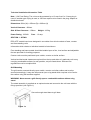
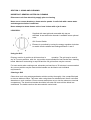
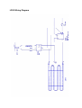
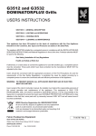
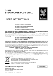
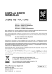
LD22 GRILL
Important Installation Information
The installer must ensure that installation of the unit(s) is in conformity with regulations in
force at the time. For the UK, particular attention requires to be paid to:BS7671 IEE Wiring Regulations
Electricity at Work Regulations
Health and Safety at Work Act
Fire Precautions Act
The unit has been CE-marked on the basis of compliance with the Low Voltage and EMC
Directives for the voltage stated on the data plate.
WARNING: THIS APPLIANCE MUST BE EARTHED!
Preventive Maintenance Contract
In order to obtain maximum performance from the equipment, we would recommend that a
maintenance contract be arranged with Serviceline. Visits may then be made at agreed
intervals to carry out adjustments and repairs. A quotation for this service will be provided
upon request. Contact Serviceline as detailed below:Tel: 01438 363 000
Fax: 01438 369 900
WEEE Directive Registration No. WEE/DC0059TT/PRO
At end of unit life, dispose of appliance and any replacement parts in a safe
manner, via a licenced waste handler.
Units are designed to be dismantled easily and recycling of all material is
encouraged whenever practicable.
Falcon Foodservice Equipment
Wallace View, Hillfoots Road, Stirling. FK9 5PY
Tel: 01786 455 200
Fax: 01786 469 454
e-mail: [email protected]
T100322 Ref. 3
Technical Installation Information Table
Note * 13A Fuse Rating: The unit must be protected by a 13 amp fuse if a 13 amp plug is
used. If another type of plug is used, a 15A fuse requires to be used in the plug, adaptor or
distribution board.
Dimensions 600m (W) x 350mm (D) x 285mm (H)
Vertical Clearance - 900mm
Side & Rear Clearance - 150mm
Power Rating - 2.65kW
Weight - 18.5kg
Fuse - 13 amp
SECTION 1 - SITING
PRO-LITE models have been designed in a modular form which consists of base, counter
and free-standing units.
Information which relates to individual models is listed above.
Free-standing and base models should be installed upon a firm, level surface and adjustable
feet are provided for levelling purposes.
Counter units must be positioned upon a table, counter or similar surface.
Vertical and horizontal clearances required from the top and sides of a particular unit to any
overlying combustible surface (ie wall, partition, etc) are listed above. Relevant fire
regulations must be complied with.
Grill Mounting
The grill can be mounted directly upon a table, counter or similar surface and must be
secured accordingly. It may also be secured upon a leg stand which requires to be fixed to
the surface using the brackets supplied.
WARNING: Never mount a grill directly upon a combustible surface without a leg
stand.
The stand assembly is supplied as an optional extra and secured to the unit base with the
fixings provided (see Figure 1).
Secure through stand base to grill base
Figure 1a
Leg bracket fixing centres
Figure 1b
Grill Fixings
To wall
The leg locating brackets then require to be secured to the worktop surface using the
appropriate fixings. The fixing centres are indicated in Figure 1b. The brackets should then
be rotated to ensure that the location holes correspond with the side fixing hole in each leg.
Locate the brackets up inside the legs and insert one fixing in each to secure the assembly.
A further option is to position the grill upon an optional shelf bracket (see Figure 2). The
installer should ensure that the wall upon which the shelf is to be mounted can support the
weight. This requires to be plugged to accommodate No.8 wood screws or equivalent of at
least 50mm in length.
To fix, hold the shelf horizontally in the desired position and mark the fixing holes through the
flanges prior to drilling. Insert the plugs and secure the bracket firmly in position. The grill
should then be placed upon the bracket and located using the fixings provided.
Either option requires an installation clearance of 50mm at the sides and rear to be
observed.
SECTION 2 ELECTRICAL SUPPLY AND CONNECTION
Electrical ratings are as stated on the unit data plate. The listing in Table 1 is based on
standard UK specification at 230V. Wiring must be executed in accordance with the
regulations listed in this booklet.
WARNING: Each individual appliance must be earthed!
After completion of installation, the method of operation should be demonstrated to the
kitchen staff. The isolating switch location, for use in an emergency or during cleaning
should also be pointed out.
This model is designed to be connected to a single phase AC supply using the 2 metre
mains lead fitted as standard.
Wires are coloured in accordance with the following code and should be connected to the
plug as follows:
EARTH to terminal marked E
NEUTRAL to terminal marked N
LIVE to terminal marked L.
Units which receive power from a plug, adaptor or distribution board must be individually
protected by a fuse with an appropriate rating.
Any replacement supply cable must be 1.5mm², cord code designation 245 IEC 57
(CENELEC H05 RN-F).
For internal connection, outer sheathing must be stripped 140mm from the cable end. The
live and neutral conductors must be trimmed so that the Earth conductor is longer by 50mm.
Pass inlet cable through the rear panel cord grip and ensure that the cable is routed without
leaving excessive free length inside the appliance.
SECTION 3 - USING AND CLEANING
IMPORTANT: GENERAL NOTES ON CLEANING
Disconnect unit from electricity supply prior to cleaning
Never use a coarse abrasive to clean exterior panels. A soft cloth with a warm water
and detergent solution is sufficient.
Never attempt to steam clean a unit or hose it down with a jet of water.
LD22 GRILL
Supplied with toast grid and removable drip tray as
standard. A cast aluminium brander is available as an optional
extra.
Grill Control Switch
Element is controlled by turning the energy regulator clockwise
to enable infinite variable heat settings between 1 and 6.
Using the Grill
Drip tray must be in position at all times when in
operation. The grid may be used in
any of 5 runner positions with the top position recommended for best results when toasting
bread. Maximum heat setting is required and the full grid surface may be covered.
For best results when cooking meat, a brander pre-heat time of 30 minutes is recommended.
Any runner position may be used and the brander can be tilted to suit individual
requirements.
Cleaning a Grill
Clean when cool using a detergent/water solution and dry thoroughly. Use a soap-filled pad
to remove stubborn stains. Take care when using these on stainless steel. Never use harsh
abrasives on such a surface. Ensure excess water does not run into the element or terminal
compartment. The aluminium brander should be left under full heat until the debris has
carbonised. The debris can then be removed with a wire brush.
LD22 GRILL SERVICE ACCESS
Removal of Control Panel
Undo fixing on RH underside of control panel. Lower panel to clear top edge catch.
FUNCTIONAL COMPONENTS
Temperature Controls
Remove control panel.
Remove electrical connections, noting the positions.
Remove control knob.
Undo fixings which secure control to panel and remove.
Replace in reverse order.
Neon Indicator
Remove control panel.
Remove electrical connections.
Undo retaining nut to remove neon.
Replace in reverse order.
Terminal Block/Cable Grip
Remove control panel.
Remove electrical connections at terminal block, noting the positions.
Undo fixings which secure the block to the unit and remove.
Replace in reverse order.
Mains Power Cable
Remove control panel.
Undo mains lead cable and grip at unit rear.
Undo electrical connections at terminal block and remove cable.
Replace in reverse order. Ensure cable is fed through securing clamp and pulled taut before
tightening the clamp.
Element
Remove control panel.
Undo element electrical connections, noting positions.
Undo element panel fixings and remove element.
Replace in reverse order.
PROLITE GRILL SHORT SPARES
737630010
Element
737630011
Energy Regulator
735110050
Control Knob
730962010
Mains Neon
735011110
Supply Cable
LD22 Wiring Diagram