1
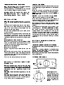
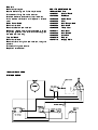
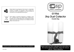
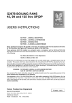
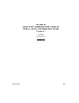
Important Installation Information
The installer must ensure that installation of the unit(s) is in conformity with
regulations in force at the time. For the UK, particular attention requires to be paid
to:BS7671 IEE Wiring Regulations
Electricity at Work Regulations
Health and Safety at Work Act
Fire Precautions Act
The unit has been CE-marked on the basis of compliance with the Low Voltage and
EMC Directives for the voltage stated on the data plate.
WARNING: THIS APPLIANCE MUST BE EARTHED!
Preventive Maintenance Contract
In order to obtain maximum performance from the equipment, we would recommend
that a maintenance contract be arranged with AFE Serviceline. Visits may then be
made at agreed intervals to carry out adjustments and repairs. A quotation for this
service will be provided upon request. Contact AFE Serviceline as detailed below:Tel: 01438 363 000
Fax: 01438 369 900
Falcon Foodservice Equipment
Wallace View, Hillfoots Road, Stirling. FK9 5PY
Tel: 01324 554 221
Fax: 01324 552 211
e-mail: [email protected]
T100321 Ref. 4
LD62 and LD64 OVENS
Technical Installation Information
* 13A Fuse Rating: The unit must be protected by
a 13 amp fuse if a 13 amp plug is used.
If another type of plug is used, a 15A fuse requires to be
used in the plug, adaptor or distribution board.
Note
- 600mm (W) x 550mm (D) x 650mm (H)
Side & Rear Clearance - 150mm
Weight - 41kg
Power Rating - 2.65kW
Fuse - 13 amp
Base Unit
SECTION 1 - SITING
PRO-LITE models have been designed in a modular
form which consists of base, counter and free-standing
units.
Information which relates to the ovens is listed above.
Free-standing and base models should be installed
upon a firm, level surface and adjustable feet are
provided for levelling purposes.
Counter units must be positioned upon a table, counter
or similar surface.
Vertical and horizontal clearances required from the top
and sides of a particular unit to any overlying
combustible surface (ie wall, partition, etc) are also
listed above. Relevant fire regulations must be complied
with.
Mounting Counter Units on an Oven
When mounting a counter unit upon the LD62 and LD64
ovens, it is recommended that units which carry liquids,
i.e. fryers and bain marie, are secured as follows:
Remove oven outer back panel.
Remove oven crown plate.
Position unit(s) which require to be secured upon the
oven.
Secure hob unit(s) to oven through side flange centre
holes into the threaded inserts in the base(s) of the hob
unit(s). Use fixings provided (packed separately) and
replace oven back panel.
The unit is now ready for electrical connection.
These models are designed to be connected to a single
phase AC supply using the 2 metre mains lead fitted as
standard.
Wires are coloured in accordance with the following
code and should be connected to the plug as follows:
EARTH to terminal marked E or coloured GREEN or
GREEN/YELLOW.
NEUTRAL to terminal marked N or coloured BLACK.
LIVE to terminal marked L or coloured RED.
Units which receive power from a plug, adaptor or
distribution board must be individually protected by a
fuse with an appropriate rating. (See Table 1)
For models with two mains leads, each lead requires to
be protected by a fuse with an appropriate rating. (See
Table 1)
Any replacement supply cable must be 1.5mm2, cord
code designation 245 IEC 57 (CENELEC H05 RN-F).
For internal connection, outer sheathing must be
stripped 140mm from the cable end. The live and
neutral conductors must be trimmed so that the Earth
conductor is longer by 50mm. Pass inlet cable through
the rear panel cord grip and ensure that the cable is
routed without leaving excessive free length inside the
appliance.
SECTION 3 - USING AND CLEANING
PRO-LITE UNITS
IMPORTANT: GENERAL NOTES ON CLEANING
Disconnect
unit
from
electricity
supply
prior
to
cleaning
Never
use
panels.
A
a
coarse
soft
cloth
abrasive
with
a
to
clean
warm
exterior
water
and
detergent solution is sufficient.
Never attempt to steam clean a unit or hose it down
with a jet of water.
LD62 and LD64 Ovens
SECTION 2 - ELECTRICAL SUPPLY AND
Mains
Neon
CONNECTION
Electrical
ratings
are
as
stated
on
the
unit
data
plate. The listing in Table 1 is based on standard UK
specification at 230V
accordance
with
~. Wiring must be executed in
the
regulations
listed
in
Thermostat Control
Thermostat Neon
this
booklet.
WARNING:
Each
individual
appliance
must
be
earthed!
After completion of installation, the method of operation
should be demonstrated to the kitchen staff. The
isolating switch location, for use in an emergency or
during cleaning should also be pointed out.
Operating Controls
A thermostat and
indicator neons monitor
operation of the oven.
The thermostat may be
set at temperatures
between 100 o C and
270oC.
Switching ON
Crown Plate
Connect and switch on at mains. The red neon will light.
Turn thermostat to required setting. The amber neon
will light. When amber neon goes out, the oven has
reached the required temperature.
Undo fixings and remove crown plate. Replace in
reverse order.
Switching OFF
Remove top hinge fixings.
Lift door to remove. Replace in reverse order and
ensure door seals correctly.
Turn thermostat back fully anti-clockwise.
The red neon will remain lit.
Switch off and disconnect at mains.
Loading
When the set temperature is reached the amber neon
will go out, the elements are off but the fan will still run.
The oven is now ready to load.
If the oven cools, the thermostat will activate power to
the elements and maintain set temperature. Load the
oven quickly to prevent heat loss.
Shelves
These are designed to prevent being pulled out
accidentally. To remove a shelf, pull forward to stop
position and tilt up. When replacing a shelf, insert with
rail stop to the rear.
There are six runner positions. For even shelf cooking,
distances between trays should be consistent. Shelf
combinations with regard to position should be 2/4/6
(from the top) or 3/6.
A typical shelf load may be 12 x 56g (2oz) scones, 12 x
225g (8oz) jacket potatoes or 3 x 500g tin bread loaves.
Times and temperatures will vary according to the
quality and quantity of the food being prepared.
Never overload the oven as excessive restriction of
air circulation will affect the cooking quality.
Cleaning an Oven
Interior
Wipe with soft cloth using a warm water and detergent
solution. Thoroughly rinse and dry.
Under no circumstances should abrasives, scrapers,
knives, scourers, paste, bleaches, steel wool with or
without soap, aerosol or proprietory oven cleaning pads
be used on enamelled panels.
LD62 and LD64 OVENS
SERVICE ACCESS
Outer Back Panel
Slacken mains lead cord grip.
Undo back panel fixings to remove panel.
When replacing panel, ensure cable is pulled taught
and tightened in a manner which securely grips the
cable within the fitting.
Shelf Hangers
Lift hanger to withdraw.
Replace in reverse order. Ensure hangers locate
correctly within the fixings with the narrow section of
the keyhole slots at the top.
DOOR ITEMS
Door Panel
Door Handle
Remove door as detailed above.
Drill out pop rivets on the door edges and separate door
halves.
Undo nuts which secure handle to door and remove
handle.
Replace in reverse order.
Door Catch
Remove door as detailed above.
Drill out pop rivets on the door edges and separate door
halves.
Drill out catch rivets and remove catch. Replace in
reverse order.
FUNCTIONAL COMPONENTS
Thermostat
Remove crown plate or counter model (Refer to Siting
section).
Remove control knob.
Remove electrical connections, noting the positions.
Undo fixings which secure thermostat to control panel
and ensure earth wire is held out of the way.
Undo fixings which retain oven phial guard and remove
guard.
Remove phial by feeding it back through hole in oven
side.
Remove sleeving.
Replace in reverse order and ensure cable is pulled
taught and tightened in a manner which securely grips
the cable within the fitting.
Fan
Remove shelf hangers.
Slacken baffle fixings and lift from keyhole slots.
Remove outer back panel.
Remove fan motor and earth lead connections.
Undo impellor retaining nut (LH thread) and remove
impellor.
Undo fixings which retain motor within oven chamber.
Replace in reverse order.
Neons
Remove crown plate or Counter model (Refer to Siting
section).
Remove electrical connections.
Undo neon retaining nut and remove neon.
Replace in reverse order.
Elements
Remove shelf hangers.
Slacken baffle fixings and lift from keyhole slots.
Undo element fixings from inside the oven.
Withdraw elements, take care not to pull the wires.
Undo element connections and replace in reverse
order.
PRO-LITE SHORT SPARES
Mains Power Cable
Remove outer back.
Remove cable from terminal block.
Replace in reverse order and ensure cable is pulled
taught and tightened in a manner which securely grips
the cable within the fitting.
Terminal Block
Remove outer back.
Remove internal wiring from terminal block, noting the
positions.
Undo block fixings and remove.
Replace in reverse order.
LD62 and LD64 OVENS
WIRIING DIAGRAM
LD62 and LD64 Oven
735270001
Control Knob
735110060
Red Neon
735270002
Amber Neon
735270003
Foot
735270004
Door Keeper Stud
735270005
Door Catch
735270006
Thermostat
735270011
Door Seal
735270008
Door Handle
735270009
Oven Fan
735270012
Element
735110110
Supply Cable